Samsung Telephone Dcs 408 Users Manual Programming_v2_
DCS-408 to the manual 913553d6-cc7c-47b9-a9bb-b91db5847c6e
2015-01-23
: Samsung Samsung-Samsung-Telephone-Dcs-408-Users-Manual-283182 samsung-samsung-telephone-dcs-408-users-manual-283182 samsung pdf
Open the PDF directly: View PDF ![]() .
.
Page Count: 276 [warning: Documents this large are best viewed by clicking the View PDF Link!]
- Publication Information
- Contents
- Part 1. Introduction to Programming
- Part 2. Program MMC List & Default Data
- Part 3. Special Applications
- Part 4. MMC Programs
- 100-121
- MMC: 100 STATION LOCK
- MMC: 101 CHANGE USER PASSCODE
- MMC: 102 CALL FORWARD
- MMC: 103 SET ANSWER MODE
- MMC: 104 STATION NAME
- MMC: 105 STATION SPEED DIAL
- MMC: 106 STATION SPEED DIAL NAME
- MMC: 107 KEY EXTENDER
- MMC: 108 STATION STATUS
- MMC: 109 DATE DISPLAY
- MMC: 110 STATION ON/OFF
- MMC: 111 KEYSET RING TONE
- MMC: 112 ALARM REMINDER
- MMC: 113 VIEW MEMO NUMBER
- MMC: 114 STATION VOLUME
- MMC: 115 SET PROGRAMMED MESSAGE
- MMC: 116 ALARM AND MESSAGE
- MMC: 119 SET CLIP DISPLAY
- MMC: 121 KEYSET LANGUAGE
- 200-220
- MMC: 200 OPEN CUSTOMER PROGRAMMING
- MMC: 201 CHANGE CUSTOMER PASSCODE
- MMC: 202 CHANGE FEATURE PASSCODES
- MMC: 203 ASSIGN UA DEVICE
- MMC: 204 COMMON BELL CONTROL
- MMC: 205 ASSIGN LOUD BELL
- MMC: 206 BARGE-IN TYPE
- MMC: 207 ASSIGN VM/AA PORT
- MMC: 208 ASSIGN RING TYPE
- MMC: 209 ASSIGN ADD-ON MODULE
- MMC: 210 CUSTOMER ON/OFF
- MMC: 211 DOOR RING ASSIGNMENT
- MMC: 212 ALARM RINGING STATION
- MMC: 213 ALARM MESSAGE
- MMC: 214 DISA ALARM RINGING STATION
- MMC: 215 VOICE DIALLER OPTIONS
- MMC: 216 VOICE DIALLER ASSIGNMENTS
- MMC: 217 CCC OPTION
- MMC: 219 COMMON RELAY SERVICE TYPE
- MMC: 220 ISDN SERVICE TYPE
- 300-319
- MMC: 300 CUSTOMER ON/OFF PER STATION
- MMC: 301 ASSIGN STATION COS
- MMC: 302 PICKUP GROUPS
- MMC: 303 ASSIGN BOSS/SECRETARY
- MMC: 304 ASSIGN STATION / TRUNK USE
- MMC: 305 ASSIGN FORCED CODE
- MMC: 306 HOT LINE
- MMC: 308 ASSIGN BACKGROUND MUSIC SOURCE
- MMC: 309 ASSIGN STATION MUSIC ON HOLD
- MMC: 310 LCR CLASS OF SERVICE
- MMC: 311 ASSIGN SIM PARAMETER
- MMC: 312 ALLOW CLIP
- MMC: 313 ASSIGN PIN CODE
- MMC: 314 CONFIRM OUTGOING CALL
- MMC: 315 SET RELOCATION
- MMC: 316 COPY STATION USABLE
- MMC: 317 ASSIGN STATION/STATION USE
- MMC: 318 DISTINCTIVE RING
- MMC: 319 BRANCH GROUP
- 400-428
- MMC: 400 CUSTOMER ON/OFF PER TRUNK
- MMC: 401 C.O. / PBX LINE
- MMC: 402 TRUNK DIAL TYPE
- MMC: 403 TRUNK TOLL CLASS
- MMC: 404 TRUNK NAME
- MMC: 405 TRUNK NUMBER
- MMC: 406 TRUNK RING ASSIGNMENT
- MMC: 407 FORCED TRUNK RELEASE
- MMC: 408 ASSIGN TRUNK MUSIC ON HOLD SOURCE
- MMC: 409 TRUNK STATUS READ
- MMC: 410 ASSIGN DISA TRUNK
- MMC: 411 ASSIGN E1 SIGNAL TYPE
- MMC: 412 ASSIGN TRUNK SIGNAL
- MMC: 414 MPD/PRS SIGNAL
- MMC: 415 REPORT TRUNK
- MMC: 416 ASSIGN AC15 TRANSLATION
- MMC: 417 PRI CRC4 OPTION
- MMC: 418 CARD RESTART
- MMC: 419 BRI OPTION
- MMC: 420 PRI OPTION
- MMC: 421 MSN DIGIT
- MMC: 422 ASSIGN TRUNK COS
- MMC: 423 S/T MODE
- MMC: 424 S0 MAPPING
- MMC: 426 TRUNK GAIN CONTROL
- MMC: 427 R2MFC SIGNAL
- MMC: 428 ASSIGN TRUNK / TRUNK USE
- 500-512
- MMC: 500 SYSTEM-WIDE COUNTERS
- MMC: 501 SYSTEM-WIDE TIMERS
- MMC: 502 STATION-WIDE TIMERS
- MMC: 503 TRUNK-WIDE TIMERS
- MMC: 504 PULSE MAKE/BREAK RATIO
- MMC: 505 ASSIGN DATE AND TIME
- MMC: 506 TONE CADENCE
- MMC: 507 ASSIGN AUTO NIGHT TIME
- MMC: 508 CALL COST
- MMC: 509 C.O. TONE CADENCE
- MMC: 510 SLI RING CADENCE
- MMC: 511 MW LAMP CAD
- MMC: 512 ASSIGN HOLIDAY
- 600-608
- 700-757
- MMC: 700 COPY COS CONTENTS
- MMC: 701 ASSIGN COS CONTENTS
- MMC: 702 TOLL DENY TABLE
- MMC: 703 TOLL ALLOWANCE TABLE
- MMC: 704 ASSIGN WILD CHARACTER
- MMC: 705 ASSIGN SYSTEM SPEED DIAL
- MMC: 706 SYSTEM SPEED DIAL BY NAME
- MMC: 707 AUTHORISATION CODE
- MMC: 708 ACCOUNT CODE
- MMC: 709 PBX ACCESS CODE
- MMC: 710 LCR DIGIT TABLE
- MMC: 711 LCR TIME TABLE
- MMC: 712 LCR ROUTE TABLE
- MMC: 713 LCR MODIFY DIGIT TABLE
- MMC: 714 DDI NUMBER AND NAME TRANSLATION
- MMC: 715 PROGRAMMED STATION MESSAGE
- MMC: 716 UK LCR OPTION
- MMC: 717 PIN CODE
- MMC: 718 MY AREA CODE
- MMC: 720 COPY KEY PROGRAMMING
- MMC: 721 SAVE STATION KEY PROGRAMMING
- MMC: 722 STATION KEY PROGRAMMING
- MMC: 723 SYSTEM KEY PROGRAMMING
- MMC: 724 DIAL NUMBERING PLAN
- MMC: 725 SMDR OPTIONS
- MMC: 726 VM/AA OPTIONS
- MMC: 727 SYSTEM VERSION DISPLAY
- MMC: 728 CLIP TRANSLATION TABLE
- MMC: 730 AA RECORD GAIN
- MMC: 731 AA RAM CLEAR
- MMC: 732 AA TRANSLATION TABLE
- MMC: 733 AA PLAN TABLE
- MMC: 734 AA MESSAGE MATCH
- MMC: 735 AA USE TABLE
- MMC: 736 ASSIGN AA MOH
- MMC: 737 DECT SYSTEM CODE
- MMC: 738 DECT CLEAR REGISTRATION
- MMC: 739 BSI DOWNLOAD
- MMC: 740 STATION PAIR
- MMC: 741 BSI CARD RESTART
- MMC: 742 BSI STATUS
- MMC: 743 DBS STATUS
- MMC: 744 DECT REGISTRATION ON/OFF
- MMC: 745 BSI CARRIER
- MMC: 750 VM CARD RESTART
- MMC: 751 ASSIGN MAILBOX
- MMC: 752 AUTO RECORD
- MMC: 753 WARNING DESTINATION
- MMC: 754 VM HALT
- MMC: 755 VM ALARM
- MMC: 756 ASSIGN VM MOH
- MMC: 757 VM IN/OUT
- 800-812
- MMC: 800 ENABLE TECHNICIAN
- MMC: 801 CHANGE TECHNICIAN PASSCODE
- MMC: 802 CUSTOMER ACCESS MMC NUMBER
- MMC: 803 ASSIGN TENANT GROUP
- MMC: 804 SYSTEM I/O PARAMETER
- MMC: 805 TX LEVEL AND GAIN
- MMC: 806 CARD PRE-INSTALL
- MMC: 807 VOLUME CONTROL
- MMC: 808 T1 TRUNK CODING
- MMC: 809 SYSTEM MMC LANGUAGE
- MMC: 810 HALT PROCESSING
- MMC: 811 RESET SYSTEM
- MMC: 812 SELECT COUNTRY
- 100-121

SAMSUNG
COMBINED
PROGRAMMING
MANUAL
for
DCS
DCS COMPACT
DCS COMPACT II
DCS-816
DCS-408
DCS-408i
DCS

Publication Information
Samsung Telecoms reserves the right without prior notice to revise information in
this publication for any reason.
Samsung Telecoms also reserves the right without prior notice to make changes in
design or components of equipment as engineering and manufacturing may warrant.
Disclaimer
Samsung Telecoms is not responsible for errors or problems arising from customers
not installing, programming or operating their Samsung systems as described in this
manual.
Copyright 2001
Samsung Telecoms (UK) Limited
All rights reserved. No part of this manual may be reproduced in any form or by any
means – graphic, electronic or mechanical, including recording, taping, photocopy or
information retrieval system – without express written permission of the publisher of
this material.
Part No.:12623 Version 2.0
EU Declaration of Conformity
For other directives relevant to DCS Compact II, DCS-816, DCS-408 and DCS-408i systems,
refer to the Samsung website at:
www.samsung-telecoms.co.uk

DCS CONTENTS
COMBINED PROGRAMMING MANUAL NOVEMBER 2001
Contents
Part
1 Introduction to Programming .....................................1–1
1.1 Using this Manual...........................................................................1–1
1.2 Programming Overview..................................................................1–2
1.3 Programming Levels......................................................................1–2
1.3.1 System Level ............................................................................ 1–2
1.3.2 Customer Level......................................................................... 1–2
1.3.3 Station Level............................................................................. 1–3
1.4 Keys Used for Programming..........................................................1–3
1.4.1 Soft Keys.................................................................................. 1–3
1.4.2 Other Keys ............................................................................... 1–3
1.5 Programming Procedures..............................................................1–4
1.5.1 Precautions When Programming ............................................... 1–4
1.5.2 Opening System or Customer Level Programming ..................... 1–4
1.5.3 Opening Station Level Programming.......................................... 1–5
1.5.4 Programming DCS-408 and 408i Systems.................................. 1–5
2 Program (MMC) List and Default Data ......................2–1
2.1 Program (MMC) List.......................................................................2–1
2.2 Default Data....................................................................................2–3
2.3 System Configuration: Quick Reference...................................... 2–9
3 Special Applications ....................................................3–1
Voice Mail / Auto Attendant Integration...................................................3–2
Individual Station Page............................................................................3–4
CLIP (Calling Line Identification Presentation)........................................3–5
Toll Restriction (Call Barring) Overview...................................................3–6
S0 Overview.............................................................................................3–8
4 MMCs (in numerical order) ........................................4–1

DCS INTRODUCTION
COMBINED PROGRAMMING MANUAL NOVEMBER 2001
1-1
Part 1. Introduction to Programming
This manual describes the MMC programming required for the following types of Sam-
sung DCS keyphone system:
• DCS
• DCS Compact (Compact I)
• DCS Compact II
• DCS-816
• DCS-408
• DCS-408i.
In this manual, these systems are referred to as “DCS,” “Compact I (CI),” “Compact II
(CII)," "816," "408" and “408i” respectively. Programming requirements for these system
types are generally the same, but occasionally there are differences. Users of 408 and
408i systems should also read Programming DCS-408 and 408i Systems in section 1.5.4
of this manual. Unless otherwise stated, references to “DCS” include Compact I sys-
tems.
The different system types are discussed fully in the separate Samsung General De-
scription manuals for each system, where these have been published.
Software Version Numbers
The software version numbers of the systems for which this programming manual is
relevant are: DCS and Compact II=V6.10 or later; 816=V1.09 or later; 408 and
408i=1.04 or later.
1.1 Using This Manual
• It is recommended that you read the whole of Part 1 of this manual which provides a
useful overview to MMC programming procedures.
• For a comprehensive list of available MMCs, see Part 2.
• For quick reference, Part 2 also provides a table listing the default settings for each
MMC and indicating which systems can use each MMC. A “Y” (“Yes”) in the appro-
priate column indicates that it can be used for that system.
• To quickly check allowed configuration settings for each type of system—number of
trunk group members, card port numbers, and so on—see section 2.3 System Con-
figuration: Quick Reference in Part 2.
• To begin programming, refer to the appropriate MMC(s) in Part 4. Check the se-
lected MMC header bar to make sure the program is available on your system, if
you haven’t already done so.
• Refer to Part 3, Special Applications, for further information on voice mail / auto at-
tendant integration, individual station paging, CLIP (Calling Line Identification Pres-
entation), toll restriction (call barring) and S0 programming.

DCS INTRODUCTION
COMBINED PROGRAMMING MANUAL NOVEMBER 2001
1-2
1.2 Programming Overview
When the keyphone system arrives from the factory it contains default data. This needs
to be customised, using the MMC programs, to suit the customer’s requirements.
MMC stands for Man Machine Code and each MMC is assigned a three-digit code (100,
101, and so on). These MMCs are used to view, create or change customer data on a
display keyphone (called KMMC programming). For example, MMC 601 is used to cre-
ate a station group; system speed dial numbers are entered in MMC 705; key functions
are assigned to individual keyphones (or “keysets”) using MMC 722; and system dial-
ling codes (such as extension numbers and feature codes) can be changed in MMC
724.
1.3 Programming Levels
There are three levels of programming: System level, Customer level and Station level.
System and Customer levels allow system-wide programming and are under passcode
protection to restrict access. System programming is done by the system installer (or
system technician), usually on a one-off basis, but also to manage any changes in the
customer’s requirements. Customer programming is done by the system administrator,
on a day to day basis, to manage station users’ requirements. Station level program-
ming does not require a passcode, allowing station users to make simple changes to
their keyset features.
To prevent conflicting data from being entered, only one person at a time can enter Sys-
tem or Customer programming. If you attempt to enter programming mode while an-
other keyset is being used for programming, your display shows [xxx PGM MODE]
where “xxx” is the keyset extension number of the station in programming mode. While
programming is in progress, normal system operation is not affected.
1.3.1 System Level
This level is entered via MMC 800 and requires the installer’s (technician’s) passcode.
This is the highest level and allows access to all system programs, station programs
and maintenance programs. The installer (sometimes called the installing technician)
also decides which programs are accessible to the customer (the system administrator)
at Customer level.
• All MMCs are accessible at this level.
1.3.2 Customer Level
This level is entered via MMC 200 and requires the customer’s passcode. It allows ac-
cess to station programs and system programs permitted by the system installer in
MMC 802. When the system administrator uses the customer passcode to access sta-
tion programs, data for all stations can be viewed or changed. Changes can be made
either system-wide or to selected keysets. (The system administrator should also refer
to the System Administration manual for their keyphone system if this is available.)
• Accessible MMCs at this level are designated by the installer.
DCS INTRODUCTION
COMBINED PROGRAMMING MANUAL NOVEMBER 2001
1-3
1.3.3 Station Level
The system administrator or keyset user can access certain programs at a station with-
out using a passcode. At this level, only data for the selected station can be changed.
You should refer to the instructions provided in the Samsung DCS Keyset User Guide.
• Accessible MMCs at this level are nos. 100–121.
1.4 Keys Used for Programming
Programming may be done from any 6-button (6B), 12-button (12B) or 24-button (24B)
keyset with a liquid crystal display (LCD). (Refer to the Samsung DCS Keyset User Guide
for a full description of keyset operation.)
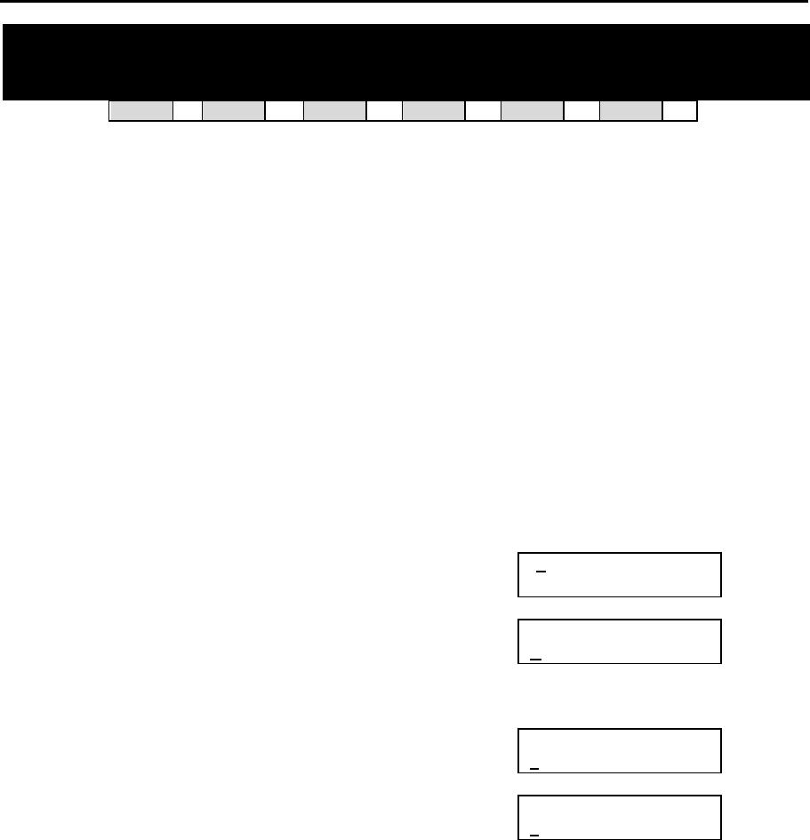
1.4.1 Soft Keys
The three keys directly below
the LCD are called soft keys.
The left-hand soft key is desig-
nated as the LEFT soft key. This
key is used to save any
changed data while program-
ming, or to move the cursor to
the left on the LCD.
The right-hand soft key is des-
ignated as the RIGHT soft key.
This key is used to save any
changed data while program-
ming, or to move the cursor to
the right on the LCD.
DCS Euro Display Keysets
1.4.2 Other Keys
The following keys perform special functions:
VOLUME UP (+) / DOWN (–) Scroll up/down through available options*
KEYPAD Enter data using keys 0–9 and [, and dial options*
HOLD Clear previous entry
ANS/RLS Select “ALL” option (e.g. to make data apply to all,
rather than selected, stations)
SPEAKER Store data and advance to next MMC
TRSF Enter programming mode or
Store data and exit programming mode
* Note: Many MMCs allow you to dial codes using the keypad to select options quickly. Alterna-
tively, you can press the VOLUME Up and Down keys (+ and –) to scroll through and select op-
tions. Use whichever method you prefer.

DCS INTRODUCTION
COMBINED PROGRAMMING MANUAL NOVEMBER 2001
1-4
The 6, 12 or 24 extra programmable keys can be set up to perform specific functions
when pressed during normal operation. During programming, some of these keys also
perform other specific functions. This is described in the individual MMC program pro-
cedure where applicable.
1.5 Programming Procedures
1.5.1 Precautions When Programming
• The keyset must be on-hook (handset down) to allow programming.
• Programming is available on any digital keyset with an LCD.
• Programming is available only on digital telephones (not analogue ones).
• If ‘INVALID DATA’ appears in the LCD while programming, you should re-enter the
correct data.
• When you have successfully completed an entry, the LCD automatically changes for
the next step.
• Programming halts if you have not pressed a key for a certain period of time (30 sec-
onds by default, but this can be changed).
• Programming halts if you pick up the handset while programming.
• If you pick up the handset while programming, or the telephone plug is pulled out,
any new data shown in the LCD are saved.
IMPORTANT
When installing and programming a ‘default’ system
for the first time:
The system requires that you select the correct software version for your coun
try
(e.g. by selecting “UK”) before you can do any other programming via either a ke
y-
phone (KMMC programming) or a PC (PCMMC programming).
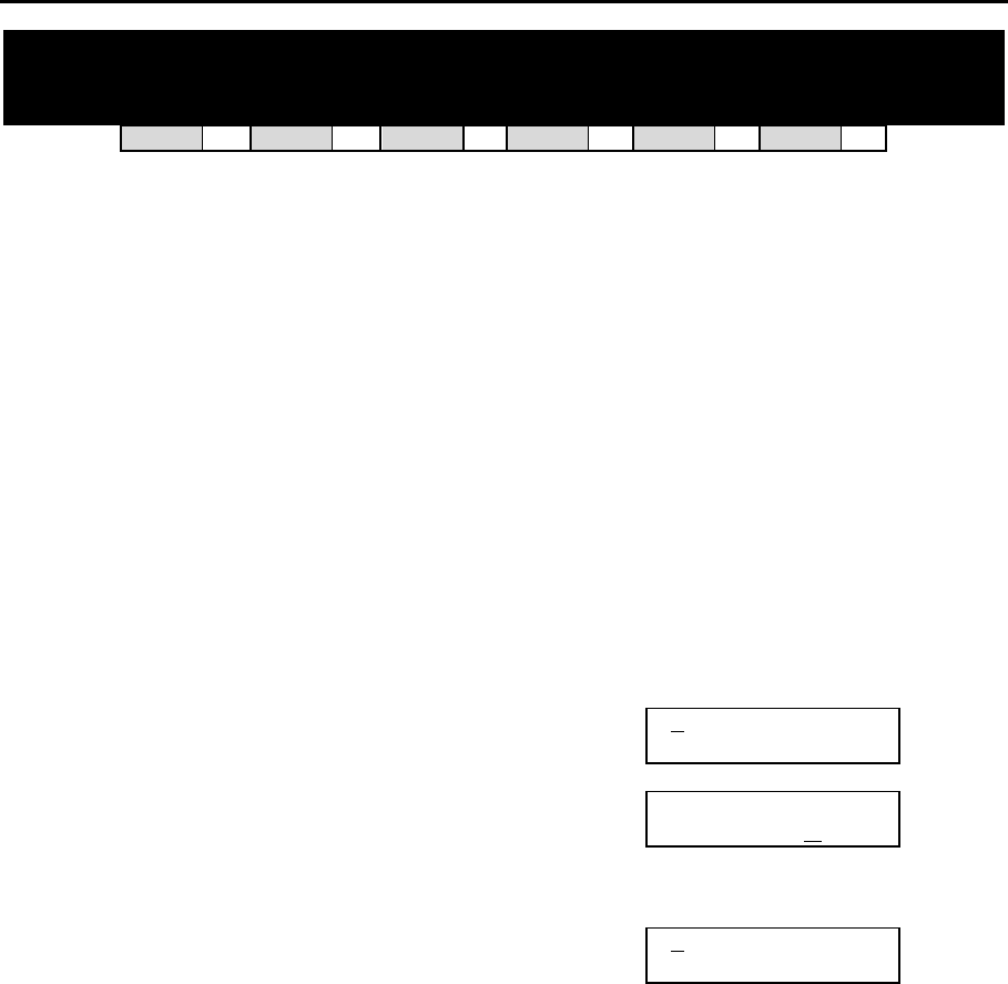
To select the country:
1. Press the TRSF key.
2. Enter 800 followed by the default passcode (4321)
The system sounds a warning and displays on the keyset:
Use the VOLUME Up/Down keys to
select the country and press the RIGHT soft key.
The keyset displays:
Use the VOLUME Up/Down keys to select YES and press the RIGHT soft key. When
defaulted to the correct version, you can open programming as de
scribed next. The
country version selected can be changed in MMC 812, Select Country.
ENABLE TECH. PROG
SELECT COUNTRY
DEFAULTING SYSTM
ARE YOU SURE? NO

DCS INTRODUCTION
COMBINED PROGRAMMING MANUAL NOVEMBER 2001
1-5
1.5.2 Opening System or Customer Programming
To open programming:
1. Press the TRSF key.
2. Enter the MMC program number 200 (for Customer level programming) or 800 (for
System level programming).
3. Enter the relevant passcode.
4. Press key 1 (or use the VOLUME Up or Down key) to select ‘ENABLE’.
5. Press the SPEAKER key to have the program selection mode appear (or press the
TRSF key to halt programming).
6. Enter the MMC number, or select the program number with the Up or Down key and
press the SPEAKER key.
When opening system programming, you are advised to check MMC 812 (Select Coun-
try) to ensure that the correct country has been selected before you do any other pro-
gramming.
Carefully follow the instructions given with each MMC to program your system correctly.
1.5.3 Opening Station Level Programming
To open programming:
1. Press the TRSF key.
2. Enter the MMC program number.
Carefully follow the instructions given with each MMC to program your system correctly.
1.5.4 Programming DCS-408 and 408i Systems
Although physically similar in appearance, the “408” and “408i” are different systems and
may have different programming requirements and features. For example, the 408i sup-
ports ISDN whereas the 408 does not. Thus, an MMC relevant to one system may not be
relevant to the other. Similarly, where an MMC relates to both systems, some features
available on the 408i system may not be available on the 408 system, and vice versa.
This will be indicated in the MMC description, where appropriate.
These systems also differ significantly from all other keyphone systems, both in size and
physical appearance. In comparison with other systems, when programming your 408 or
408i:
• Extension, group and trunk numbers are two digits by default (e.g. extension 21,
trunk 71, etc). All other systems use 3-digit numbers by default (e.g. extension 201,
trunk 701, etc).* Examples of programming shown in this manual use 3-digit num-
bers for convenience only.
(*Unless changed by the system installer in MMC 724.)
• You can set up to four ‘Normal’ station groups. Group types AA, VM/AA and UCD
are not permitted.
• Only two trunk groups, 8 and 9, are available. (All other systems support groups 9
and 80–82.)

DCS MMC LIST
COMBINED PROGRAMMING MANUAL NOVEMBER 2001
2-1
Part 2. Program MMC List & Default Data
2.1 Program (MMC) List
100: STATION LOCK 317: ASSIGN STATION/STATION USE
101: CHANGE USER PASSCODE 318: DISTINCTIVE RING
102: CALL FORWARD 319: BRANCH GROUP
103: SET ANSWER MODE 400: CUSTOMER ON/OFF PER TRUNK
104: STATION NAME 401: CO/PBX LINE
105: STATION SPEED DIAL 402: TRUNK DIAL TYPE
106: STATION SPEED DIAL NAME 403: TRUNK TOLL CLASS
107: KEY EXTENDER 404: TRUNK NAME
108: STATION STATUS 405: TRUNK NUMBER
109: DATE DISPLAY 406: TRUNK RING ASSIGNMENT
110: STATION ON/OFF 407: FORCED TRUNK RELEASE
111: KEYSET RING TONE 408: ASSIGN TRUNK MUSIC ON HOLD SOURCE
112: ALARM REMINDER 409: TRUNK STATUS READ
113: VIEW MEMO NUMBER 410: ASSIGN DISA TRUNK
114: STATION VOLUME 411: ASSIGN E1 SIGNAL TYPE
115: SET PROGRAMMED MESSAGE 412: ASSIGN TRUNK SIGNAL
116: ALARM AND MESSAGE 414: MPD/PRS SIGNAL
119: SET CLIP DISPLAY 415: REPORT TRUNK ABANDON DATA
121: KEYSET LANGUAGE 416: ASSIGN AC15 TRANSLATION
200: OPEN CUSTOMER PROGRAMMING 417: PRI CRC4 OPTION
201: CHANGE CUSTOMER PASSCODE 418: CARD RESTART
202: CHANGE FEATURE PASSCODES 419: BRI OPTION
203: ASSIGN UA DEVICE 420: PRI OPTION
204: COMMON BELL CONTROL 421: MSN DIGIT
205: ASSIGN LOUD BELL 422: ASSIGN TRUNK COS
206: BARGE-IN TYPE 423: S/T MODE
207: ASSIGN VM/AA PORT 424: S0 MAPPING
208: ASSIGN RING TYPE 426: TRUNK GAIN CONTROL
209: ASSIGN ADD-ON MODULE 427: R2MFC SIGNAL
210: CUSTOMER ON/OFF 428: ASSIGN TRUNK/TRUNK USE
211: DOOR RING ASSIGNMENT 500: SYSTEM-WIDE COUNTERS
212: ALARM RINGING STATION 501: SYSTEM-WIDE TIMERS
213: ALARM MESSAGE 502: STATION-WIDE TIMERS
214: DISA ALARM RINGING STATION 503: TRUNK-WIDE TIMERS
215: VOICE DIALLER OPTIONS 504: PULSE MAKE/BREAK RATIO
216: VOICE DIALLER ASSIGNMENTS 505: ASSIGN DATE AND TIME
217: CCC OPTION 506: TONE CADENCE
219: COMMON RELAY SERVICE TYPE 507: ASSIGN AUTO NIGHT TIME
220: ISDN SERVICE TYPE 508: CALL COST
300: CUSTOMER ON/OFF PER STATION 509: C.O. TONE CADENCE
301: ASSIGN STATION COS 510: SLI RING CADENCE
302: PICKUP GROUPS 511: MW LAMP CAD
303: ASSIGN BOSS/SECRETARY 512: ASSIGN HOLIDAY
304: ASSIGN STATION/TRUNK USE 600: ASSIGN OPERATOR GROUP
305: ASSIGN FORCED CODE 601: ASSIGN STATION GROUP
306: HOT LINE 602: STATION GROUP NAME
308: ASSIGN BACKGROUND MUSIC SOURCE 603: ASSIGN TRUNK GROUP
309: ASSIGN STATION MUSIC ON HOLD 604: ASSIGN STATION TO PAGE ZONE
310: LCR CLASS OF SERVICE 605: ASSIGN EXTERNAL PAGE ZONE
311: ASSIGN SIM PARAMETER 606: ASSIGN SPEED BLOCK
312: ALLOW CLIP 607: UCD OPTIONS
313: ASSIGN PIN CODE 608: ASSIGN CLIP REVIEW BLOCK
314: CONFIRM OUTGOING CALL 700: COPY COS CONTENTS
315: SET RELOCATION 701: ASSIGN COS CONTENTS
316: COPY STATION USABLE 702: TOLL DENY TABLE

DCS MMC LIST
COMBINED PROGRAMMING MANUAL NOVEMBER 2001
2-2
703: TOLL ALLOWANCE TABLE 736: ASSIGN AA MOH
704: ASSIGN WILD CHARACTER 737: DECT SYSTEM CODE
705: ASSIGN SYSTEM SPEED DIAL 738: DECT CLEAR REGISTRATION
706: SYSTEM SPEED DIAL BY NAME 739: BSI DOWNLOAD
707: AUTHORISATION CODE 740: STATION PAIR
708: ACCOUNT CODE 741: BSI CARD RESTART
709: PBX ACCESS CODE 742: BSI STATUS
710: LCR DIGIT TABLE 743: DECT BASE STATION (DBS) STATUS
711: LCR TIME TABLE 744: DECT REGISTRATION ON/OFF
712: LCR ROUTE TABLE 745: BSI CARRIER
713: LCR MODIFY DIGIT TABLE 750: VM CARD RESTART
714: DDI NUMBER & NAME TRANSLATION 751: ASSIGN MAILBOX
715: PROGRAMMED STATION MESSAGE 752: AUTO RECORD
716: UK LCR OPTION 753: WARNING DESTINATION
717: PIN CODE 754: VM HALT
718: MY AREA CODE 755: VM ALARM
720: COPY KEY PROGRAMMING 756: ASSIGN VM MOH
721: SAVE STATION KEY PROGRAMMING 757: VM IN/OUT
722: STATION KEY PROGRAMMING 800: ENABLE TECHNICIAN PROGRAM
723: SYSTEM KEY PROGRAMMING 801: CHANGE TECHNICIAN PASSCODE
724: DIAL NUMBERING PLAN 802: CUSTOMER ACCESS MMC NUMBER
725: SMDR OPTIONS 803: ASSIGN TENANT GROUP
726: VM/AA OPTIONS 804: SYSTEM I/O PARAMETER
727: SYSTEM VERSION DISPLAY 805: TX LEVEL & GAIN
728: CLIP TRANSLATION TABLE 806: CARD PRE-INSTALL
730: AA RECORD GAIN 807: VOLUME CONTROL
731: AA RAM CLEAR 808: T1 TRUNK CODING
732: AA TRANSLATION TABLE 809: SYSTEM MMC LANGUAGE
733: AA PLAN TABLE 810: HALT PROCESSING
734: AA MESSAGE MATCH 811: RESET SYSTEM
735: AA USE TABLE 812: SELECT COUNTRY

DCS DEFAULT DATA
COMBINED PROGRAMMING MANUAL NOVEMBER 2001
2-3
2.2 Default Data
Station Programs
DCS CI CII 816 408 408i
100: STATION LOCK Y Y Y Y Y Y ALL STATIONS UNLOCKED
101: CHANGE USER PASSCODE Y Y Y Y Y Y ALL STATION PASCODES=1234
102: CALL FORWARD Y Y Y Y Y Y ALL STATION=0 (FWD CANCEL)
103: SET ANSWER MODE Y Y Y Y Y Y ALL KEYSETS ‘RING’
RING FREQUENCY DEFAULT=5
104: STATION NAME Y Y Y Y Y Y NONE
105: STATION SPEED DIAL Y Y Y Y Y Y NONE
106: STATION SPEED DIAL NAME Y Y Y Y Y Y NONE
107: KEY EXTENDER Y Y Y Y Y Y NONE
108: STATION STATUS Y Y Y Y Y Y SEE MMC 108
109: DATE DISPLAY Y Y Y Y Y Y COUNTRY: WESTERN
CLOCK: 24-HOUR
DISPLAY: LOWERCASE
110: STATION ON/OFF Y Y Y Y Y Y AUTO HOLD: OFF
AUTO TIMER: ON
HEADSET MODE: OFF
HOT KEYPAD: ON
KEY TONE: ON
PAGE REJOIN: ON
RING PREFERENCE: ON
CALL COST: OFF
AME BGM: OFF
AME PSWD: OFF
111: KEYSET RING TONE Y Y Y Y Y Y SELECTION=5
112: ALARM REMINDER Y Y Y Y Y Y ALARMS SET TO NOTSET
113: VIEW MEMO NUMBER Y Y Y Y Y Y NO MEMOS ENTERED
114: STATION VOLUME Y Y Y Y Y Y RING VOL: 4
OFF HOOK RING VOL: 4
HANDSET VOL: 4
SPEAKER VOL: 13
BGM VOL: 13
115: SET PROGRAMMED MESSAGE Y Y Y Y Y Y NO MESSAGES SELECTED
116: ALARM AND MESSAGE Y Y Y Y Y Y ALARMS SET TO NOTSET
119: SET DISPLAY Y Y Y Y N Y NAME FIRST
121: KEYSET LANGUAGE Y N Y Y Y Y ENGLISH
DCS DEFAULT DATA
COMBINED PROGRAMMING MANUAL NOVEMBER 2001
2-4
System Programs
DCS CI CII 816 408 408i
200: OPEN CUSTOMER PROGRAMMING Y Y Y Y Y Y CLOSED (DISABLED)
201: CHANGE CUSTOMER PASSCODE Y Y Y Y Y Y PASSCODE =1234
202: CHANGE FEATURE PASSCODES Y N Y Y Y Y DAY/NIGHT=0000
DISA ALARM=5678
ALARM CLR=8765
AA RECORD=4321
DECT (BSI) REGISTER =4321
203: ASSIGN UA DEVICE Y Y Y Y Y Y NONE
204: COMMON BELL CONTROL Y Y Y Y Y Y CONTINUOUS
205: ASSIGN LOUD BELL Y N Y Y Y Y UNASSIGNED
206: BARGE-IN TYPE Y Y Y Y Y Y NO BARGE IN
207: ASSIGN VM/AA PORT Y Y Y Y Y Y NORMAL PORT
208: ASSIGN RING TYPE Y Y Y Y Y Y ICM RING
209: ASSIGN ADD-ON MODULE Y Y Y Y N N NONE FOR MASTER
210: CUSTOMER ON/OFF Y Y Y Y Y Y SEE MMC 210
211: DOOR RING ASSIGNMENT Y Y Y Y Y Y STATION GROUP 500 (or 50)
212: ALARM RINGING STATION Y N Y N N N ALL SENSORS RING 500
DAY/NIGHT
213: ALARM MESSAGE Y N Y N N N NONE
214: DISA ALARM RINGING STATION Y Y Y Y Y Y DAY/NIGHT=500 (or 50)
215: VOICE DIALLER OPTIONS Y Y Y N N N 2CH-7USER-20BIN
216: VOICE DIALLER ASSIGNMENTS Y Y Y N N N NONE
217: CCC OPTION N Y N N N N NONE
219: COMMON RELAY SERVICE TYPE N N Y Y Y Y SEE MMC 219
220: ISDN SERVICE TYPE Y Y Y Y N Y VOICE
300: CUSTOMER ON/OFF PER STATION Y Y Y Y Y Y STN CALL PRT : OFF
FWD DLY USE : OFF
OTHER FEATURES SET TO
ON
301: ASSIGN STATION COS Y Y Y Y Y Y DAY CLASS = 1
NIGHT CLASS = 1
302: PICKUP GROUPS Y Y Y Y Y Y ALL STATIONS GROUP 1
303: ASSIGN BOSS/SECRETARY Y Y Y Y Y Y NONE
304: ASSIGN STATION/TRUNK USE Y Y Y Y Y Y DIAL = YES
ANS = YES
305: ASSIGN FORCED CODE Y Y Y Y Y Y NONE
306: HOT LINE Y Y Y Y Y Y NONE
308: ASSIGN BACKGROUND MUSIC
SOURCE Y Y Y Y Y Y NONE
309: ASSIGN STATION MUSIC ON HOLD Y Y Y Y Y Y NONE
310: LCR CLASS OF SERVICE Y Y Y Y Y Y LEAST COST ROUTING
COS 1

DCS DEFAULT DATA
COMBINED PROGRAMMING MANUAL NOVEMBER 2001
2-5
DCS CI CII 816 408 408i
311: ASSIGN SIM PARAMETER Y N N N N N SIM TYPE = DTE
CALL MODE = MANUAL
ANS MODE = MANUAL
AUTO BAUD = ON
DTR CHECK = ON
ECHO = ON
PROTOCOL = V110
SPEED = 9600
CHAR LENGTH = 8 BITS
PARITY = NONE
STOP BIT = 1
312: ALLOW CLIP Y Y Y Y N Y RCV=YES, SEND=YES,
INFO=CO Tel
313: ASSIGN PIN CODE N Y N N N N ALL STATIONS ARE CODE
#1
314: CONFIRM OUTGOING CALL Y N Y Y Y Y NONE
315: SET RELOCATION Y N Y Y Y Y NONE
316: COPY STATION USABLE Y N Y Y N N NONE
317: ASSIGN STATION/STATION USE Y N Y Y N N DIAL=YES
318: DISTINCTIVE RING Y N Y Y Y Y T=F-STN, C=F-STN
319: BRANCH GROUP – – – – – – NOT USED IN UK
400: CUSTOMER ON/OFF PER TRUNK Y Y Y Y Y Y 1A2 EMULATE: OFF
TRUNK INC DND: OFF
TRUNK FORWARD: ON
LCR ALLOW:OFF
401: C.O./PBX LINE Y Y Y Y Y Y ALL TRUNKS C.O. LINE
402: TRUNK DIAL TYPE Y Y Y Y Y N ALL TRUNKS DTMF
403: TRUNK TOLL CLASS Y Y Y Y Y Y ALL TRUNKS F-STN
DAY/NIGHT
404: TRUNK NAME Y Y Y Y Y Y NO NAMES ENTERED
405: TRUNK NUMBER Y Y Y Y Y Y NO NUMBERS ENTERED
406: TRUNK RING ASSIGNMENT Y Y Y Y Y Y ALL TRUNKS DAY/NIGHT:
500 (or 50)
407: FORCED TRUNK RELEASE Y Y Y Y Y Y NONE
408: ASSIGN TRUNK MUSIC ON HOLD
SOURCE Y Y Y Y Y Y TONE
409: TRUNK STATUS READ Y Y Y Y Y Y SEE MMC 409
410: ASSIGN DISA TRUNK Y Y Y Y Y Y ALL TRUNKS NORMAL
411: ASSIGN E1 SIGNAL TYPE – – – – – – NOT USED IN UK
412: ASSIGN TRUNK SIGNAL Y Y Y N N N IMMEDIATE
414: MPD/PRS SIGNAL Y Y Y Y Y N NONE
415: REPORT TRUNK ABANDON DATA Y Y Y Y N Y REPORT=YES
416: ASSIGN AC15 TRANSLATION Y Y Y N N N UNUSE DID TRANS
417: PRI CRC4 OPTION Y N Y N N N CRC4 ON
418: CARD RESTART Y Y Y Y N Y NONE

DCS DEFAULT DATA
COMBINED PROGRAMMING MANUAL NOVEMBER 2001
2-6
DCS CI CII 816 408 408i
419: BRI OPTION Y Y Y Y N Y CHANNEL ANY: YES
BRI MODE: P-P DDI
DLSEND: OVERLAP
BRI CODING: A-LAW
POWERFEED: NO
420: PRI OPTION Y N Y N N N CHANNEL ANY: YES
PRI MODE: DDI
DLSEND: OVERLAP
421: MSN DIGIT Y Y Y Y N Y NONE
422: ASSIGN TRUNK COS Y Y Y Y Y Y DAY CLASS: 1
NIGHT CLASS: 1
423: S/T MODE Y Y Y Y N Y TRUNK
424: S0 MAPPING Y Y Y Y N Y NONE
426: TRUNK GAIN CONTROL Y N Y Y Y Y RX=+0.0 dB, TX=+0.0 dB
(ALL TRUNKS)
427: R2MFC SIGNAL N N N N N N NOT USED IN UK
428: ASSIGN TRUNK/TRUNK USE Y N Y Y N N DIAL=YES
500: SYSTEM-WIDE COUNTERS Y Y Y Y Y Y SEE MMC 500
501: SYSTEM-WIDE TIMERS Y Y Y Y Y Y SEE TABLE OF TIMERS
AND VALUES IN MMC 501
502: STATION-WIDE TIMERS Y Y Y Y Y Y NO ANS FWD: 015 SEC
DTMF DURATION: 100 MS
FIRST DGT DELAY: 600 MS
503: TRUNK-WIDE TIMERS Y Y Y Y Y Y ANS.BAK TM: 600 MS
CLEARING: 002 SEC
CO SUPV TM: 400 MS
DTMF DURATION: 100 MS
FIRST DGT DELAY: 600 MS
FLASH TIME: 070 MS
NO RING TM: 004 SEC
PAUSE TIME: 003 SEC
PRS DET TM: 000 MS
RNG DET.TM: 300 MS
WINK: 200 MS
MF/DP INT TM: 0800 MS
MFR DLY TM: 000 SEC
504: PULSE MAKE/BREAK RATIO Y Y Y Y Y N MAKE/BREAK = 33
PULSES PER SECOND = 10
505: ASSIGN DATE AND TIME Y Y Y Y Y Y FOLLOWS S/W VERSION
RELEASE DATE
506: TONE CADENCE Y Y Y Y Y Y SEE MMC 506
507: ASSIGN AUTO NIGHT TIME Y Y Y Y Y Y NONE
508: CALL COST Y Y Y Y Y Y UNIT COST PER MP: 200
PENCE
CALL COST RATE: 100%
509: C.O. TONE CADENCE N Y N N N N SEE MMC 509
510: SLI RING CADENCE Y Y Y Y Y Y SEE MMC 510
511: MW LAMP CAD Y N Y N N N ON: 1000MS, OFF: 1000MS
512: ASSIGN HOLIDAY Y N Y Y Y Y NONE
600: ASSIGN OPERATOR GROUP Y Y Y Y Y Y DAY/NIGHT: 500 (or 50)

DCS DEFAULT DATA
COMBINED PROGRAMMING MANUAL NOVEMBER 2001
2-7
DCS CI CII 816 408 408i
601: ASSIGN STATION GROUP Y Y Y Y Y Y SEE MMC 601
602: STATION GROUP NAME Y Y Y Y Y Y NONE
603: ASSIGN TRUNK GROUP Y Y Y Y Y Y SEE MMC 603
604: ASSIGN STATION TO PAGE ZONE Y Y Y Y Y Y NO STATIONS ASSIGNED
’ALL ZONE’ IS SET
605: ASSIGN EXTERNAL PAGE ZONE Y Y Y Y Y Y NONE
606: ASSIGN SPEED BLOCK Y Y Y Y Y Y SYSTEM: SEE MMC 606
STATIONS: ONE BIN OF 10
ENTRIES
607: UCD OPTIONS Y Y Y Y N N SEE MMC 607
608: ASSIGN CLIP REVIEW BLOCK Y Y Y Y N Y ONE BIN OF 10 ENTRIES
700: COPY COS CONTENTS Y Y Y Y Y Y NONE
701: ASSIGN COS CONTENTS Y Y Y Y Y Y TOLL LEVEL: ALL COS=A
ALL FEATURES (EXCL.
OVERRIDE)=YES
702: TOLL DENY TABLE Y Y Y Y Y Y ALL ENTRIES=0
703: TOLL ALLOWANCE TABLE Y Y Y Y Y Y ALL ENTRIES=0
704: ASSIGN WILD CHARACTER Y Y Y Y Y Y ALL X, Y, Z=1
705: ASSIGN SYSTEM SPEED DIAL Y Y Y Y Y Y NONE
706: SYSTEM SPEED DIAL BY NAME Y Y Y Y Y Y NO NAMES
707: AUTHORISATION CODE Y Y Y Y Y Y NONE
708: ACCOUNT CODE Y Y Y Y Y Y NONE
709: PBX ACCESS CODE Y Y Y Y Y Y NONE
710: LCR DIGIT TABLE Y Y Y Y Y Y DEPENDS ON S/W VER-
SION
711: LCR TIME TABLE Y Y Y Y Y Y SEE MMC 711
712: LCR ROUTE TABLE Y Y Y Y Y Y SEE MMC 712
713: LCR MODIFY DIGIT TABLE Y Y Y Y Y Y DEPENDS ON S/W VER-
SION
714: DDI NUMBER AND NAME TRANSLA-
TION Y Y Y Y N Y SEE MMC 714
715: PROGRAMMED STATION
MESSAGE Y Y Y Y Y Y 20 MESSAGES (10 PRE-
PROGRAMMED) (SEE MMC
715)
716: UK LCR OPTIONS Y Y Y Y Y Y SEE MMC 716
717: PIN CODE N Y N N N N NONE
718: MY AREA CODE – – – – – – NOT USED IN UK
720: COPY KEY PROGRAMMING Y Y Y Y Y Y NONE
721: SAVE STATION KEY PROGRAMMING Y Y Y Y Y Y RESTORE
722: STATION KEY PROGRAMMING Y Y Y Y Y Y SEE MMC 722
723: SYSTEM KEY PROGRAMMING Y Y Y Y Y Y SEE MMC 723
724: DIAL NUMBERING PLAN Y Y Y Y Y Y SEE MMC 724
725: SMDR OPTIONS Y Y Y Y Y Y SEE MMC 725
726: VM/AA OPTIONS Y Y Y Y Y Y SEE MMC 726

DCS DEFAULT DATA
COMBINED PROGRAMMING MANUAL NOVEMBER 2001
2-8
DCS CI CII 816 408 408i
727: SYSTEM VERSION DISPLAY Y Y Y Y Y Y INSTALLED CARD VERSIONS
728: CLIP TRANSLATION TABLE Y Y Y Y N Y NONE
730: AA RECORD GAIN Y N Y Y N N +0.0 dB
731: AA RAM CLEAR Y Y Y Y N N NONE
732: AA TRANSLATION TABLE Y Y Y Y N N SEE MMC 732
733: AA PLAN TABLE Y Y Y Y N N SEE MMC 733
734: AA MESSAGE MATCH Y Y Y Y N N MSG INDEX NO.
735: AA USE TABLE Y Y Y Y N N PLAN 01
736: ASSIGN AA MOH Y Y Y Y N N NOT USE
737: DECT SYSTEM CODE Y Y Y N N N AUTH CODE: FFFF
SYSTEM ID: 000
738: DECT CLEAR REGISTRATION Y Y Y N N N FORCED MODE
739: BSI DOWNLOAD Y Y Y N N N NONE
740: STATION PAIR Y Y Y Y N N NONE
741: BSI CARD RESTART Y Y Y N N N NONE
742: BSI STATUS Y Y Y N N N NONE
743: DBS STATUS Y Y Y N N N NONE
744: DECT REGISTRATION ON/OFF Y Y Y N N N DISABLE
745: BSI CARRIER Y Y Y N N N 1111111111
750: VM CARD RESTART Y N Y N N N DOWNLOAD=YES
751: ASSIGN MAILBOX Y N Y N N N ALL STN=YES, ALL GRP=NO
752: AUTO RECORD Y N Y N N N MB=NONE, PORT=NONE
CALL=I
753: WARNING DESTINATION Y N Y N N N DEST=500
754: VM HALT Y N Y N N N NONE
755: VM ALARM Y N Y N N N THRESHOLD=80%
756: ASSIGN VM MOH Y N Y N N N NOT USE
757: VM IN/OUT Y N Y N N N IN/OUT
800: ENABLE TECHNICIAN PROGRAM Y Y Y Y Y Y DISABLE
801: CHANGE TECHNICIAN PASSCODE Y Y Y Y Y Y DEFAULT PASSCODE = 4321
802: CUSTOMER ACCESS MMC NO. Y Y Y Y Y Y SEE MMC 802
803: ASSIGN TENANT GROUP Y N N N N N ALL ASSIGNMENTS TENANT 1
804: SYSTEM I/O PARAMETER Y Y Y Y Y Y SEE MMC 804
805: TX LEVEL AND GAIN Y Y Y Y Y Y SEE MMC 805
806: CARD PRE-INSTALL Y Y Y Y N N NONE
807: VOLUME CONTROL Y Y Y Y Y Y SEE MMC 807
808: T1 TRUNK CODING – – – – – – NOT USED IN UK
809: SYSTEM MMC LANGUAGE Y N Y Y Y Y ENGLISH
810: HALT PROCESSING Y Y Y Y N N NONE
811: RESET SYSTEM Y Y Y Y Y Y NONE
812: SELECT COUNTRY Y N Y Y Y Y NONE

2.3 System Configuration: Quick Reference
Description DCS Compact I Compact II 816 408 408i
AA card port numbers 3951–8 3951–6 381–61 381–4 N/A N/A
AA Translation tables 1 & 2 (entries) 100 100 100 50 N/A N/A
Account codes 500 250 200 200 100 100
Authorisation codes 250 100 100 30 10 10
BGM port numbers 3701–2 371–2 371–2 371–2 371 371
CALL keys (max.) 8 8 5 4 2 2
Classes of Service (COS) 30 30 30 10 4 4
CLIP Translation Table entries 250 250 200 200 N/A 100
Daughterboards (keyset) KSU Any DLI port Motherboard None None None
DDI entries 200 200 200 50 N/A 20
DECT ports 48 24 24 N/A N/A N/A
LCR Digit Table (max. entries) 500 500 500 300 100 100
MOH port numbers 3701–2 371–2 371–2 371–2 371 371
Operator Groups (part of Station Group) 1 1 1 1 1 1
Operator Group members (sequential / dis-
tributed ring) 32 30 30 16 8 8
Operator Group members (unconditional
ring) 32 30 10 16 8 8
Page zones (no. of internal) 4 4 4 4 2 2
Page zones (no. of external) 4 4 4 1 1 1
Pickup Groups 20 20 20 8 4 4
2-9
S0 bus ports 32 32 24 16 None 2

2.3 System Configuration: Quick Reference (cont’d)
Description DCS Compact I Compact II 816 408 408i
Speed dials (total) 1500 500 600 500 300 300
Speed dials (system)(max.) 500 500 500 300 200 200
Station Groups (number of) 30 30 20 10 4 4
Station Group members (sequential / dis-
tributed ring) 48 30 30 16 8 8
Station Group members (unconditional
ring) 32 30 10 16 8 8
Station Group numbers 500–529 500–529 500–519 500–509 50–53 50–53
Trunk Groups (number of) 11 11 11 4 2 2
Trunk Group members 80 10 40 10 4 4
Trunk Group numbers 9, 80–89 9, 80–89 9, 80–89 9, 80–82 9, 8 9, 8
UCD Groups 102 102 53 34 N/A N/A
2-10
Voice dial card port numbers 3551–2 3551–2 355–6 N/A N/A N/A
Notes:
1Misc 2 card=381–4, AA card=381–6, both cards installed=381–90
2UCD Group can be created from any Station Group 501–529 (CI) or last 10 Station Groups 520–529 (DCS)
3UCD Group can only be created from last 10 Station Groups 510–519
4UCD Group can only be created from last three Station Groups 507–509

DCS SPECIAL APPLICATIONS
COMBINED PROGRAMMING MANUAL NOVEMBER 2001
3-1
Part 3. Special Applications
Part 3 provides additional information covering the following topics:
• Voice Mail / Auto Attendant Integration
• Individual Station Page
• CLIP (Calling Line Identification Presentation)
• Toll Restriction (Call Barring) Overview
• S0 Overview

DCS SPECIAL APPLICATIONS
COMBINED PROGRAMMING MANUAL NOVEMBER 2001
3–2
Voice Mail/Auto Attendant Integration
(In-Band / SMDI )
This section focuses mainly on in-band integration. Systems may alternatively accommo-
date Bellcore standard SMDI—available by setting in MMC 210 (SMDI VMS SET option).
Because of the increased popularity of voice mail and auto attendant use, all DCS systems
include many programmable options to address this demand. The degree of integration
that can be achieved depends on the abilities of the voice mail/auto attendant (VM/AA) sys-
tem as well as the telephone system.
The following describes the capabilities provided by systems for voice mail via in-band inte-
gration.
Hardware Provisions
• The VM/AA system must be connected to single line circuits on any SLI card.
• Each port is equipped with a dedicated DTMF receiver for detecting DTMF signalling
from the VM/AA.
• These ports also provide an instant break in loop current when the calling party
hangs up. This is called a disconnect signal.
Software Provisions
• Screened Or Unscreened Transfer
There are no special codes needed to transfer a call. Simply hookflash, receive
transfer dial tone and dial the destination.
• Direct In Lines
Any C.O. call can be assigned to ring at an individual station or a station hunt group
assigned to the VM/AA.
• Calls or Recalls to the Operator
Dialling 0 will always result in a ringback signal. If the operator is busy, the call con-
tinues to ring in queue to the operator.
• Message Waiting
A VM/AA port can leave a message at any station or group of stations. The message
waiting indication can be set or cancelled at any station or station group with or with-
out the stations ringing.

DCS SPECIAL APPLICATIONS
COMBINED PROGRAMMING MANUAL NOVEMBER 2001
3–3
In-Band Signalling
Systems can be programmed to send the calling station’s extension number after
the voice mail system answers. These DTMF signals may include a leading digit to
indicate the type of call and additional information about the original caller. DTMF
signals may also be substituted for call progress tones to speed up voice mail call
processing. This program allows call forwarding to a mailbox and bypassing of the
main greeting for automatic message retrieval. Blind (unscreened) transfers may be
performed because the recall will be correctly identified.
Note: The effectiveness of this program depends on the ability of the voice mail system to
make use of this information.
• Station Hunt Group With Overflow
Each station group can have an individual overflow destination with an individual
overflow timer. The overflow destination will ring whenever a call to the group is not
answered. If the voice mail system becomes inoperative, calls are automatically
routed to the overflow destination.
• Internal Call Forwarding to Voice Mail
This option in MMC 300 provides the ability to allow or deny call forwarding of inter-
nal calls to voice mail. This feature conserves disk drive space by only storing calls
originating outside the system.
• One-Touch Voice Mail Access
One-touch speed dial keys can be programmed to automatically dial, log into and re-
trieve messages from voice mail.
• Call Progress Tones
The only tones sent to a VM/AA port are dial tone, busy and ringback. To eliminate
confusion, busy tone is substituted for DND or error tones on voice mail ports only.

DCS SPECIAL APPLICATIONS
COMBINED PROGRAMMING MANUAL NOVEMBER 2001
3–4
Individual Station Page
Keyphone systems were not designed to permit page announcements to individual keysets.
However, a forced auto answer key (FAUTO) can be used to do this.
1. Program a keyset for RING in MMC 103.
2. Assign a FAUTO key (in MMC 722) to each keyset that is allowed to page individual
keysets.
3. Call another station. When you hear ringback tone, press the FAUTO key. The ringing
will stop and an Auto Answer call is set up.
Note: To prevent the use of this feature from getting out of control, only assign FAUTO keys to those
keysets needing to page individual keysets.

DCS SPECIAL APPLICATIONS
COMBINED PROGRAMMING MANUAL NOVEMBER 2001
3–5
CLIP
(Calling Line Identification Presentation)
Hardware Provisions
ISDN trunk cards.
Software Provisions
The MMCs related to CLIP are listed below with a short description of their uses. They are listed
in the recommended order in which they should be programmed. This sequence is suggested
so that the installer/technician gets a better understanding of how the feature works. There is no
technical reason to strictly follow this sequence.
l MMC 312
(ALLOW CLIP) Used to determine which keysets are allowed to re-
ceive CLIP displays.
l MMCs 722 and 723
(STATION & SYSTEM KEY
PROGRAMMING)
It is strongly recommended that all keysets allowed
CLIP in MMC 312 are programmed with a CLIP key
using this MMC.
l MMC 728
(CLIP TRANSLATION TABLE) Allows for the creation of a list of names that corre-
spond to numbers received from the Central Office
(C.O.). These names will be displayed when a call
rings in that has NUMBER ONLY data provided by the
C.O.
l MMC 725
(SMDR OPTIONS) Provides the ability to print CLIP data and abandoned
calls on the Station Message Detail Recording
(SMDR) report.
l MMC 119
(SET CLIP DISPLAY) Station users can determine what CLIP data is dis-
played when a call rings at the user’s station.
l MMC 501
(SYSTEM-WIDE TIMERS) You may need to adjust the CLIP DISPLAY timer. This
is the length of time that CLIP data is displayed at us-
ers’ stations after the CLIP key is pressed.
l MMC 415
(REPORT TRUNK ABANDON
DATA)
Used to determine which trunks will record data in the
Call Abandon list and print with an Abandon “A” flag
on the SMDR report.
l MMC 608
(ASSIGN CLIP REVIEW BLOCK) Used to assign CLIP Review blocks to keysets to al-
low the user to review CLIP data for previous calls.
l MMC 701
(ASSIGN COS CONTENTS) All CLIP features are included in this MMC so that the
system installer can allow or deny them.
l MMC 724
(DIAL NUMBERING PLAN) CLIP features are included in this MMC to al
low the
system installer to assign an access code where nec-
essary.

DCS SPECIAL APPLICATIONS
COMBINED PROGRAMMING MANUAL NOVEMBER 2001
3–6
Toll Restriction (Call Barring)
Overview
The system allows each station to be assigned a class of service (COS) for day and night
modes. Into this COS is brought the dialling restrictions to be applied to each station. Dial-
ling restrictions are applied in MMC 702 (Toll Deny Table) and MMC 703 (Toll Allowance
Table).
Eight levels of restriction are available to stations: A, B, C, D, E, F, G and H. Level A im-
poses no restrictions on station dialling; level H restricts stations to internal calls only; and
levels B to G are programmable. In addition, the Wild Card Table (MMC 704) can be used to
provide more flexibility when programming.
Toll Restriction Rules
• The Deny Table entries prevent certain numbers being dialled.
• The Allowance Table entries are the ONLY exceptions to the Deny Table entries.
• Listing codes in the Allowance Table with no entries in the Deny Table gives “no
restriction”.
• A wild card in any position in the Deny Table means an exception exists in the Al-
lowance Table for the digits defined by the wild card.
• A wild card at the end of an entry means that more digits may be dialled.
• Never put a single wild card as an entry in the Allowance Table.
• When changing an entry in the BCDEFG status, ALL digits must be entered.
Use of Deny Table
Example
Let’s assume that you want to restrict (bar) the dialling of the following codes to your users:
0860 and 0850 car phone numbers, 0891and 0898 premium rate numbers, 00 International
numbers and 01 STD numbers. You would set up the Deny Table as follows:
TOLL DENY TABLE
ENTRY DIGITS B C D E F G
001 0860 1 0 0 0 0 0
002 0850 1 0 0 0 0 0
003 0891 1 1 1 1 0 0
004 0898 1 1 1 1 0 0
005 00 1 1 0 0 0 0
006 01 1 0 0 1 0 0
Note: The number of entries allowed varies between systems (see MMC 702).
From the above table (“1” means a number is barred):
• Stations with Toll Level B applied will be barred all the codes listed.
• Stations with Toll Level C applied will be barred 0891, 0898 and 00 calls.
• Stations with Toll Level D applied will be barred 0891 and 0898 calls.
• Stations with Toll Level E applied will be barred 0891, 0898 and 01 calls.
DCS SPECIAL APPLICATIONS
COMBINED PROGRAMMING MANUAL NOVEMBER 2001
3–7
• Stations with Toll Levels F or G applied will have no restrictions.
Use of Wild Cards and the Allowance Table
The Wild Card Table in MMC 704 appears as follows.
WILD CARD 0 1 2 3 4 5 6 7 8 9 * #
X 0 0 0 0 0 0 0 0 0 0 0 0
Y 0 0 0 0 0 0 0 0 0 0 0 0
Z 0 0 0 0 0 0 0 0 0 0 0 0
The digits 0–9, * and # are values that each of the wild cards X, Y and Z can take. This is
explained later. (You are also unlikely to use any wild card apart from X.)
In the Deny Table, the STD code 01 has been barred to users with a B or E Toll level. It may,
however, be necessary to allow some STD codes to be dialled. For example, the codes
01869, 01993, and 01235 are codes local to Oxford and you may want users in the Oxford
area to have access to these codes, with all other STD codes barred. You can achieve this
using the Wild Card Table and Toll Allowance Table as follows:
Delete entry 006 in the Deny Table and add the following entry:
TOLL DENY TABLE
ENTRY DIGITS B C D E F G
006 01XXX 1 1 1 1 0 0
and in the Toll Allowance Table make the following entries:
TOLL ALLOWANCE TABLE
ENTRY DIGITS B C D E F G
001 01869 1 1 1 1 0 0
002 01993 1 1 1 1 0 0
003 01235 1 1 1 1 0 0
In the above table, any station assigned a Toll level B, C, D or E will be allowed to dial only
01869, 01993 and 01235 numbers, but all other STD codes will be barred. Stations with a
Toll level F or G will be barred from dialling all STD codes.
The changes necessary in the Wild Card Table to implement these requirements are shown
below, where the Wild Card character X represents any value between 0 and 9 (i.e. a “1” is
placed in the field for any value that X is allowed to represent).
WILD CARD 0 1 2 3 4 5 6 7 8 9 # *
X 1 1 1 1 1 1 1 1 1 1 0 0
Y 0 0 0 0 0 0 0 0 0 0 0 0
Z 0 0 0 0 0 0 0 0 0 0 0 0

DCS SPECIAL APPLICATIONS
COMBINED PROGRAMMING MANUAL NOVEMBER 2001
3–8
S0 Overview
Contents
Introduction ..................................................................... 3–9
Specifications ..................................................................3–9
PRI ............................................................................ 3–9
BRI............................................................................ 3–9
ISDN Services .......................................................... 3–10
Installation ...................................................................... 3–12
Operation ....................................................................... 3–12
Ports ....................................................................... 3–12
PRI and BRI LT-T Mode ............................................ 3–13
BRI LT-S Mode .........................................................3–13
Features Reference Tables............................................. 3–14
Related Timers ......................................................... 3–14
PRI and BRI LT-T Port ............................................... 3–14
PRI and BRI LT-S Port ............................................... 3–16
Pin Assignment of Connectors ....................................... 3–16
PRI .......................................................................... 3–16
BRI.......................................................................... 3–16
BRI Related MMC Procedure.......................................... 3–18

DCS SPECIAL APPLICATIONS
COMBINED PROGRAMMING MANUAL NOVEMBER 2001
3–9
Introduction
In the DCS there are two line cards for ISDN. One is the PRI card containing one Primary
Rate Interface; the other is the BRIN card containing four Basic Rate Interfaces. For Com-
pact (I and II) and 816 systems there are two types of BRI card, one with two BRI access,
the other with four.
The following topics are covered:
Hardware specification of each card
Installation
Operation
ISDN features supported
Note: 1. This document is based on BRI and PRI V2.0 (Nov 4 1996) or later. Therefore, some fea-
tures are not applicable to the old version.
2. Main CPU software versions required are 4.0 or later (DCS), 2.3 or later (CII), 1.02 or later
(816).
Specifications
PRI
(The PRI option is not applicable to Compact I, 816 or 408/408i systems.)
The card has the following configuration:
Contains one PRI access with RJ-45 interface having 120Ω line termination.
Operates in LT-T mode only. You can only connect to a PSTN ISDN Network Termination
Port (NT).
BRI
The different types of BRI card are shown in Table 1.
System Card name Number of
BRI access Power feeding
to S port
DCS BRIN
BRI (old) 4
4 YES
NO
Compact II 4BRI
2BRI 4
2 YES
YES
Compact I &
816 4BRI
2BRI 4
2 NO
NO
Table 1 - BRI cards
Note: The only difference between these cards is the number of access, and power feeding capabil-
ity.
DCS SPECIAL APPLICATIONS
COMBINED PROGRAMMING MANUAL NOVEMBER 2001
3–10
Each BRI / BRIN access has the following features:
Each port operates in either LT-T or LT-S mode. Every setting is done by MMC - there is
no jumper or DIP switch to set. You can connect an NT line or ISDN terminals. (See note,
below.)
For LT-S ports, you can decide whether or not power is supplied to that port by MMC
419.
32 numbers (DCS—range 7801 to 7832) or 24 numbers (Compact II—range 7801 to
7824) are reserved for terminals attached to the LT-S ports. Each number can be as-
signed to only one port. However, a port can have more than one number. (That is, two
ISDN terminals with the same MSN number cannot exist in different LT-S ports.)
Each S0 bus must be terminated with a 100Ω termination resistor. The original BRI cards
did not have this resistor. However, it is fitted to cards manufactured from mid 1997. It is
important that this termination is present on each installation, and should be checked by
the installer.
Note: 1. In BRI, LT-T and LT-S mode can be selected only by MMC programming. However, you
should connect the Tx and Rx cable pair from the MDF correctly. Tx and Rx connections are
reversed between LT-T and LT-S mode (see Table 15).
2. If you are connecting a T0 port to an NT, take care if there is a termination present some-
where other than on the BRI card on the bus.
ISDN Services
Outgoing calls when origination party is non-S0 terminal
When an extension seizes an ISDN TRK or S0 terminal attached to the system, the ISDN
bearer capability (BC) and high layer compatibility (HLC) will be coded as in Table 2.
ORIGINATION BC HLC
DGP (Digital keyphone) Speech Telephony
SLT (ICM/CO ring in MMC 208) 3.1 kHz Audio Telephony
SLT (DATA ring in MMC 208) 3.1 kHz Audio Telephony
Table 2 - Coding of BC/HLC when an extension seizes an
ISDN TRK or S0 terminal
Incoming calls when destination party is non-S0 terminal
When an incoming call is present on the ISDN TRK or S0 port, the call will be accepted if the
following condition is satisfied (Table 3). Calls with other BC or HLC will be rejected.
DCS SPECIAL APPLICATIONS
COMBINED PROGRAMMING MANUAL NOVEMBER 2001
3–11
BC HLC DESTINATION
Speech Telephony DGP (Digital keyphone)
SLT (ICM/CO ring in MMC 208)
3.1 kHz Audio Telephony SLT (ICM/CO ring in MMC 208)
3.1 kHz Audio None DGP
SLT (ICM/CO ring in MMC 208)
3.1 kHz Audio Fax G2/3 SLT (DATA ring in MMC 208)
Table 3 - Accepted BC and HLC when destination is a non-S0 terminal
Accepted BC and HLC combinations on the ISDN TRK or S0 port
For calls between S0 and ISDN TRK, the following BC and HLC combinations (Table 4) will
be accepted, regardless of which party is the originator.
BC HLC LLC
Speech Telephony A-law
3.1 kHz Audio Telephony A-law
3.1 kHz Audio none A-law
3.1 kHz Audio Fax G2/3 A-law
Unrestricted Digital Info none none
Unrestricted Digital Info Teletex none
Unrestricted Digital Info OSI none
Unrestricted Digital Info Video New none
Unrestricted Digital Info Mixed none
56 kHz Data none none
V.110 none proper value
V.120 none proper value
Video none none
7 kHz Audio none none
Unrestricted Digital Info Fax G4 Fax G4
Table 4 - Accepted BC and HLC when destination is a non-S0 terminal
Supported bearer capability
Speech, Unrestricted Data, 3.1 kHz Audio, 7 kHz Audio, Video
Supported high layer compatibility
Telephony, G3 Fax, G4 Fax, Mixed Mode, Teletex, Videotex, Telex, OSI.
DCS SPECIAL APPLICATIONS
COMBINED PROGRAMMING MANUAL NOVEMBER 2001
3–12
Supported ISDN supplementary services
Service Note
DDI PRI DDI Mode and BRI T P-P DDI
MSN BRI T P-M MSN
CLIP Incoming call and outgoing call
Sub Addressing Sub-address of incoming / outgoing call
AOC ETSI AOC-D Currency/Unit
ETSI AOC-E Currency/Unit
Italy
Holland
Portugal
Belgium
Table 5 – Supported ISDN supplementary services
Installation
The installation procedure is as follows:
1) Switch off the power to the system.
2) Insert the card in the appropriate slot.
3) Execute MMC 811 (Reset System).
4) Carry out related MMC programming according to your intended use of the card.
5) Run MMC 418 (Card Restart).
Note:
§ In DCS, both BRI and PRI must be installed in the Basic Key Service Unit (not the Expansion
Cabinet).
§ The PRI card must be installed in the first slot with the next even-numbered slot empty.
§ 100Ω line termination may not be present on the BRI card. If not, termination should be provided
somewhere outside the BRI card.
§ In BRI, LT-T and LT-S mode can be selected only by MMC programming. However, you should
connect the Tx and Rx cable pair from MDF correctly. Tx and Rx connections are reversed be-
tween LT-T and LT-S mode (see Table 15).
Operation
Ports
After installation, the system allocates a port number to each B-channel in exactly the same
way as the analogue trunk case. Thus, a BRI will be assigned eight port numbers, while a
PRI will be assigned 30.
Note: To avoid confusion, the words "port" and "access" are used here with different meanings. "Port"
is used to specify one B-channel, while "access" specifies one BRI span which consists of two B-
channels and one D-channel.

DCS SPECIAL APPLICATIONS
COMBINED PROGRAMMING MANUAL NOVEMBER 2001
3–13
PRI & BRI LT-T Mode
Making an outgoing call
Overlap sending
You can seize a port by dialling the port number (e.g. 701). When you see SETUP ACK dis-
played on your keyset, you can dial the destination number.
Enblock sending
You can make a call through the enblock sending mode port by dialling the port number
and the destination number followed by #.
Incoming call routing
This depends on the mode of BRI/PRI set by MMC 419/420. See Table 6.
Operational mode Associated table Note
PRI NOR
BRI P-P NOR
BRI P-M NOR
MMC 406
"TRK RING" This table has global meaning -
applied to the ports set to DDI
PRI DDI
BRI P-P DDI MMC 712
"DDI TABLE" Same as above
BRI P-M NOR MMC 421
"MSN DIGIT" A table is required for each BRI
access
Table 6 - Incoming call routing according to MMC 419/420
BRI LT-S Mode
Note: All of the following examples are valid only after programming with the appropriate MMC. Refer
to Part 4 of this manual.
Making a call from a DCS subscriber (DGP/SLT) to an ISDN terminal attached to LT-S port
To call a terminal attached to an LT-S port, dial the MSN of the terminal. If a terminal with
MSN of 7803 is attached to 703, and you dialled 7803, a SETUP message will be sent out
through 703 with calling party number of 7803. All terminals with MSN of 7803 will alert.
Alternatively, to call a terminal (or terminals), dial the port number. This time the calling
party number of the SETUP message is vacant. All the terminals attached to that port will
alert, with no regard to MSN number.
In the above cases, dial is always sent in enblock mode.
Caution
When making a call from an S0 terminal, take care with the CLI number. It is usually sent when
the call is made, and if that number is not registered in MMC 424 the system will disconnect
the call.
Making a call from a terminal attached to LT-S port to a DCS subscriber (DGP/SLT)
To call a DCS subscriber from an ISDN terminal, dial the number you want to call. It is of no
concern to the BRI card whether the terminal sends the number in enblock or overlap
mode.
Making a call from a terminal attached to LT-S port to a remote terminal through a TRK
Dial the TRK number followed by the destination number. ISDN TRK and analogue TRK op-
erate in the same way as seen from a terminal. When calling through an ISDN TRK there
DCS SPECIAL APPLICATIONS
COMBINED PROGRAMMING MANUAL NOVEMBER 2001
3–14
is no relationship or restriction between the dial sending mode of the terminal and the ISDN
TRK. (DATA calls must use an ISDN TRK.)
Routing an incoming call to the terminals attached to LT-S port
Incoming calls are routed according to the properties of the selected TRK. Routing is con-
trolled by the MMC tables. You can put a terminal number into the DDI, MSN or TRUNK
RING table as a destination, with or without a wild card digit. You can then answer the in-
coming call from the terminal.
Features Reference Tables
Tables 7 and 8 explain briefly which system features are applicable to ISDN cards.
Related Timers
Feature Implemented Note
ATT Recall Time YES You can check the version of BRI or
PRI
C.O. - C.O. Disconnect NO Only for analogue trunk
Dial Pass Time NO Only for analogue trunk
DISA Disconnect NO Only for analogue trunk
DISA Lock Out Timer NO Only for analogue trunk
DISA Pass Check NO Only for analogue trunk
First Digit Time
Inter Digit Time
Overlap Inter Digit YES Inter Digit time in overlap send-
ing/receiving
Table 7 – Related DCS timers
Note: These values can be changed in MMC 501 or 503.
PRI and BRI LT-T Port
Call feature capability
Feature Implemented Note
Transfer NO Transfer to remote user through ISDN TRK is
not allowed
Conference YES Conference with remote user through ISDN
TRK
Forward YES External Forward - forward to remote user
through ISDN TRK
SMDR YES SMDR report of the calls through ISDN TRK
port
Toll Check YES Toll check through ISDN TRK port
DISA YES Use an ISDN TRK as DISA outgoing line
Table 8 - Call feature abilities of PRI & BRI LT-T

DCS SPECIAL APPLICATIONS
COMBINED PROGRAMMING MANUAL NOVEMBER 2001
3–15
MMC dependency
MMC Related Note
MMC 403 Trunk Toll Class YES
MMC 404 Trunk Name NO
MMC 404 Trunk Number NO For an outgoing call, if there is no
matching number in the DDI table this
number will be used as calling party
number
MMC 406 Trunk Ring Assignment YES PRI Mode: NOR
BRI Mode: P-P NOR, P-M NOR
MMC 407 Forced Trunk Release YES
MMC 408 Assign Trunk Music On
Hold Source YES
MMC 409 Trunk Status Read YES Displays the Cabinet / Slot / Port num-
bers
MMC 410 Assign DISA Trunk YES
MMC 411 E1TRK Signal NO
MMC 412 Assign Trunk Signal NO Only for AC15
MMC 414 MPD/PRS Signal NO Analogue only
MMC 415 Report Trunk Abandon
Data YES
MMC 416 Assign AC15 Translation NO Only for AC15
MMC 417 PRI CRC4 Option YES
MMC 418 Card Restart YES Restarts PRI or BRI
MMC 419 BRI Option YES
MMC 420 PRI Option YES
MMC 421 MSN Digit YES BRI Mode: P-M MSN
MMC 422 Assign Trunk COS YES
MMC 423 S/T Mode YES Only for BRI
MMC 424 S0 Mapping YES Only for BRI S port
MMC 508 Call Cost NO
MMC 509 C.O. Tone Cadence NO Only for Analogue trunk
MMC 603 Assign Trunk Group YES
MMC 702 Toll Deny Table YES
MMC 703 Toll Allowance Table YES
MMC 714 DDI Table YES PRI: DDI
BRI: P-P DDI
Table 9 – MMC dependency
DCS SPECIAL APPLICATIONS
COMBINED PROGRAMMING MANUAL NOVEMBER 2001
3–16
PRI and BRI LT-S Port
Call feature capability
For LT-S ports, only basic call functions are provided - you cannot use other functions
(transfer, forward, hold etc) from an LT-S terminal. However, a DGP can transfer/forward a
call to an LT-S terminal. Other features (conference, hold etc) operate in a similar way.
There is no COS check for an LT-S port.
Pin Assignment of Connectors
PRI
PRI card has one RJ-45 connector with the pin assignments shown in Table10.
Pin Number Assignment
1 Rx
2 Rx
4 Tx
5 Tx
Table 10 - Pin assignments of RJ-45 at customer premises side for PRI
BRI
Champ connector
DCS
Function Colour Colour Function
Tx of P1 W/BL BL/W Tx of P1
Rx of P1 W/O O/W Rx of P1
Tx of P2 W/BR BR/W Tx of P2
Rx of P2 W/SL SL/W Rx of P2
Tx of P3 R/O O/R Tx of P3
Rx of P3 R/GR GR/R Rx of P3
Tx of P4 R/SL SL/R Tx of P4
Rx of P4 BK/BL BL/BK Rx of P4
Table 11 - Champ connector pin assignment
(DCS)
Note: Tx and Rx has no polarity.
DCS SPECIAL APPLICATIONS
COMBINED PROGRAMMING MANUAL NOVEMBER 2001
3–17
Compact I
Function Colour Colour Function
Tx of P1 W/BL BL/W Tx of P1
Rx of P1 W/O O/W Rx of P1
Tx of P2 W/GR GR/W Tx of P2
Rx of P2 W/BR BR/W Rx of P2
Tx of P3 W/SL SL/W Tx of P3
Rx of P3 R/BL BL/R Rx of P3
Tx of P4 R/O O/R Tx of P4
Rx of P4 R/GR GR/R Rx of P4
Table 12 - Champ connector pin assignment
(Compact I)
Note: Table 12 is based on expansion slot 1 of Compact I. Tx and Rx has no polarity.
Compact II
Function Colour Colour Function
Tx of P1 SL/P P/SL Tx of P1
Rx of P1 BR/P P/BR Rx of P1
Tx of P2 GR/P P/GR Tx of P2
Rx of P2 O/P P/O Rx of P2
Tx of P3 BL/P P/BL Tx of P3
Rx of P3 SL/Y Y/SL Rx of P3
Tx of P4 BR/Y Y/BR Tx of P4
Rx of P4 GR/Y Y/GR Rx of P4
Table 13 - Champ connector pin assignment
(Compact II)
Note: Table 13 is based on expansion slot 1 of Compact II. Tx and Rx has no polarity.
816
Function Colour Colour Function
Tx of P1 W/GR GR/W Tx of P1
Rx of P1 W/BR BR/W Rx of P1
Tx of P2 W/SL SL/W Tx of P2
Rx of P2 R/BL BL/R Rx of P2
Tx of P3 R/O O/R Tx of P3
Rx of P3 R/GR GR/R Rx of P3
Tx of P4 R/BR BR/R Tx of P4
Rx of P4 R/SL SL/R Rx of P4
Table 14 - Champ connector pin assignment
(816)
Note: Tx and Rx has no polarity.

DCS SPECIAL APPLICATIONS
COMBINED PROGRAMMING MANUAL NOVEMBER 2001
3–18
RJ-45 pin assignment for BRI
User Side (LT-T) Pin Number NT Side (LT-S)
Tx 3 Rx
Rx 4 Tx
Rx 5 Tx
Tx 6 Rx
Table 15 - Pin assignment of RJ-45 for BRI
Note: DCS-408 and 408i users should refer to the Installation Manual provided with their system for
details of pin connections for BRI.
Making an RJ-45 connector extension to BRI
As shown in Table 15, LT-S (NT side) and LT-T (User side) have different pin assignments in
RJ-45. You can use the pin assignment tables (11–14) with Table 15 according to the func-
tion of the BRI port. You should connect pins with the pins in Table 15 that have the same
name.
Note: RJ-45 sockets come in different styles which look similar. However, pin numbers may be ter-
minated in different places. Therefore, always check the pin numbers on your connectors.
BRI Related MMC Procedure
There are several MMCs related to BRI cards. Because some MMCs have dependencies on
other MMCs, it could become cumbersome to do MMC programming correctly. You should,
therefore, program these MMCs in a pre-defined order, as described in this section. Be sure
to follow this order, or some of the MMC data will be lost.

DCS SPECIAL APPLICATIONS
COMBINED PROGRAMMING MANUAL NOVEMBER 2001
3–19
Order of Programming
Carry out programming as shown in the diagram, below.
Note:
1. This item does not have to be programmed prior to MMC 419 or MMC 418 (because those MMCs
have no effect on this item). However, this item must be preceded by MMC 423.
2. This item displays its name as "BRI-TRK" or "BRI-STN" according to the port setting in MMC 423.
3. This item is only applicable when a BRI access is programmed as P-MP MSN in MMC 419.
4. Only for a STATION port set in MMC 423.
Example of programming a STATION port
Assume that you have a BRI card installed in DCS and its ports are numbered from 701 to
708. You want to use the 4th BRI access (707 and 708) as a STATION port to connect ISDN
terminals. The procedure is:
MMC 423
S/T mode
MMC 424
S0 Mapping (NOTE 1)
MMC 419
BRI-STN (NOTE 2)
MMC 419
BRI-TRK (NOTE 2)
MMC 421
MSN Digit (NOTE 3)
T S
Program MSN in your
ISDN terminal (NOTE 4)
MMC 418
Card Restart

DCS SPECIAL APPLICATIONS
COMBINED PROGRAMMING MANUAL NOVEMBER 2001
3–20
Step 1
Select the functional mode of that port as STATION in MMC 423 (S/T Mode). You
can set either 707 or 708 to STATION.
Step 2
Choose whether you want to supply power to that BRI access or not. If you do, set
the POWER FEED option to YES in MMC 419.
Step 3 Restart the BRI card by executing MMC 418 (Card Restart) so that the changes you
made can take effect.
Step 4
Program MMC 424 (S0 Mapping) to map an ISDN number into a port. You must also
input the "mapped number" as MSN to the ISDN terminals connected to that BRI ac-
cess. If you mapped 7807 into 707, you must set the MSN of the terminals con-
nected to 707 (or 708) to 7807.
Now, if you dial 7807 from a keyphone (DGP), a SETUP message will be sent out
through 707 (or 708) with the called party number of 7807. There can be a number
of terminals connected to 707 (or 708) but only terminals with MSN of 7807 will alert.
Alternatively, if you dial 707 (or 708) from a DGP, SETUP message will be sent out
through 707 (or 708) without the called party number. All terminals connected to 707
(or 708) will alert.
BRI Access
In MMCs 419, 421, 423 and 424, which are related to BRI cards, you can see the "port"
number displayed as "7x(x)". Each port stands for a B-channel. Thus, two adjacent ports
make up a BRI access. You need only change the settings for one of the two ports for that
BRI access.
For example, you may see port 709 and 710 are displayed respectively in the MMCs, but
these ports are for the same BRI access. If you change settings for 709 you also change
settings for 710, and vice versa.

DCS MMC PROGRAMS
COMBINED PROGRAMMING MANUAL NOVEMBER 2001
4–1
Part 4. MMC Programs
This part contains all the MMC programs provided for your keyphone system, presented in
numerical order.
• The procedure described here for a particular MMC may be slightly different on your
system and some LCD displays may not be exactly as shown. For example, port
numbers may be different for the system you are programming. Refer to the section
System Configuration: Quick Reference in Part 1 for the relevant options for your sys-
tem.
Also, 408 and 408i systems employ 2-digit extension and group numbers by default,
unlike other systems which use 3-digit numbers by default. (These dialling number
plans can be changed by the system installer using MMC 724.)
Remember that the displays shown for each MMC in this manual are provided
as examples, and should be used for guidance only.
• To identify which MMCs apply to your system, either refer to the MMC lists at the
beginning of this manual, or locate the relevant MMC page here and refer to the tick
box beneath the title: a tick (3) next to the system name indicates it is applicable; a
cross (7) means it is not.
• The procedure described for each MMC assumes you are the installer or system
administrator with system-wide access via a passcode. However, MMCs 100–121
are also accessible to individual keyset users. If you are programming your own
keyset at Station level, the procedure is different and you should refer to your Sam-
sung DCS Keyset User Guide for details.
• The term “DCS” as used in this manual includes Compact I systems, except where
otherwise indicated.
• Make sure the correct country is first selected (MMC 812) before carrying out any
other programming.
DCS MMC PROGRAMS
COMBINED PROGRAMMING MANUAL NOVEMBER 2001
MMC 100 (Page 1 of 1)
MC: 100 STATION LOCK
DCS 33
CI 33 CII 33 816 33 408i 33 408 33
Allows the system administrator to lock or unlock an individual station or all stations simultane-
ously. The three options are:
0 UNLOCKED Unlocks a locked station.
1 LOCKED OUT Prevents the station from accessing a C.O. line and initiating an ex-
ternal call
2 LOCKED ALL Prevents the station from initiating any actions.
PROGRAM KEYS
UP & DOWN Used to scroll through options
KEYPAD Used to enter selections
SOFT KEYS Move cursor left and right
SPEAKER Used to store data and advance to next MMC
HOLD Used to clear previous entry
ANS/RLS Used to select ALL
ACTION DISPLAY
1. Open programming and select 100
Display shows [201] STN LOCK
UNLOCKED
2. Dial station number (e.g., 205)
OR [205] STN LOCK
UNLOCKED
Use UP and DOWN to select station
and use RIGHT soft key to move cursor
OR
Press ANS/RLS to select all stations [ALL] STN LOCK
??
3. Enter 0 to unlock, 1 to lock out or 2 to lock all (e.g., 1)
OR [205] STN LOCK
LOCKED OUT
Press UP or DOWN key to make
selection and press RIGHT soft key
to return to step 2
4. Press TRSF to save and exit
OR
Press SPEAKER to save and advance
to next MMC
Default Data: All stations unlocked
Related Items: Station user programming
DCS MMC PROGRAMS
COMBINED PROGRAMMING MANUAL NOVEMBER 2001
MMC 101 (Page 1 of 1)
MMC: 101 CHANGE USER PASSCODE
DCS 33 CI 33 CII 33 816 33 408i 33 408 33
Allows the system administrator to reset keyset passcodes to their default value of “1234.” This
MMC cannot display station passcodes; it can only reset them to default.
The passcode is used to lock or unlock the keyset for toll restriction (call barring) override and to
access the DISA feature.
Note:
Default passcodes cannot be used for toll restriction override, DISA access or the walking class of service
function.
PROGRAM KEYS
UP & DOWN Used to scroll through options
KEYPAD Used to enter selections
SOFT KEYS Move cursor left and right
SPEAKER Used to store data and advance to next MMC
HOLD Used to clear previous entry
ACTION DISPLAY
1. Open programming and select 101
Display shows [201] PASSCODE
PASSCODE: QQQQ
2. Dial keyset number (e.g., 205)
OR [205] PASSCODE
PASSCODE: QQQQ
Use UP or DOWN to scroll through keyset numbers
and press RIGHT soft key to move the cursor right
3. Press HOLD to reset passcode
[205] PASSCODE
PASSCODE : 1234
4. Press TRSF to store and exit
OR
Press SPEAKER to store and advance to next MMC
Default Data: All station passcodes = 1234
Related Items: MMC 100 Station Lock
DCS MMC PROGRAMS
COMBINED PROGRAMMING MANUAL NOVEMBER 2001
MMC 102 (Page 1 of 2)
MMC: 102 CALL FORWARD
DCS 33 CI 33 CII 33 816 33 408i 33 408 33
Allows the system administrator to program the call forward destinations for station users. Also
allows call forwarding to be set after the destination has been entered.
The system allows five types of call forwarding: FORWARD ALL, FORWARD BUSY, FORWARD
NO ANSWER, and FORWARD EXTERNAL. The FORWARD BUSY/NO ANSWER option allows
both BUSY and NO ANSWER options to be activated at the same time, provided that destina-
tions have already been entered for both.
0 = FORWARD CANCEL 3 = NO ANSWER
1 = ALL CALL 4 = BUSY/NO ANSWER
2 = BUSY 5 = EXT (External)
PROGRAM KEYS
UP & DOWN Used to scroll through options
KEYPAD Used to enter selections
SOFT KEYS Move cursor left and right
SPEAKER Used to store data and advance to next MMC
HOLD Used to clear previous entry
ACTION DISPLAY
1. Open programming and select 102
Display shows [201] FORWARD
0:FORWARD CANCEL
2. Dial station number (e.g., 205)
OR [205] FORWARD
0:FORWARD CANCEL
Press UP or DOWN to select station and press
RIGHT soft key to move cursor
3. Dial 0–5 to select forward type
OR [205] FORWARD
1:ALL CALL:NONE
Press UP or DOWN to select forward type and
press
RIGHT soft key to move cursor
4. Dial destination number (e.g., 201)
OR [205] FORWARD
1:ALL CALL:201
Press UP or DOWN to select destination and
press RIGHT soft key to move cursor
5. Dial 1 for YES, 0 for NO
OR [205] FORWARD
CURENTLY SET :YES
Press UP or DOWN to select YES or NO
and press RIGHT soft key to return to step 2
6. Press TRSF to store and exit
OR
Press SPEAKER to store and advance
to next MMC

DCS MMC PROGRAMS
COMBINED PROGRAMMING MANUAL NOVEMBER 2001
MMC 102 (Page 2 of 2)
Default Data: All stations 0 (Forward Cancel)
Related Items: MMC 301 Assign Station COS
MMC 501 System-Wide Timers
MMC 502 Station-Wide Timers
MMC 701 Assign COS Contents
MMC 722 Station Key Programming
MMC 723 System Key Programming
DCS MMC PROGRAMS
COMBINED PROGRAMMING MANUAL NOVEMBER 2001
MMC 103 (Page 1 of 1)
MMC: 103 SET ANSWER MODE
DCS 33 CI 33 CII 33 816 33 408i 33 408 33
Allows the system administrator to change the answer mode of any keyset. Each keyset can
have its answer mode set to one of the following options:
0. RING: The keyset will ring in one of eight custom ring patterns. Calls are answered by pressing
the ANS/RLS key or by lifting the handset.
1. AUTO ANSWER: After giving a short attention tone, the keyset will automatically answer calls
on the speakerphone. When a C.O. line is transferred to a keyset in Auto Answer mode, the
screened portion of the call will be Auto Answer, but the keyset will ring when the transfer is
complete if the user has not pressed the ANS/RLS key or lifted the handset.
2. VOICE ANNOUNCE: The keyset will not ring. After a short attention tone, callers can make an
announcement but the ANS/RLS key or handset must be used to answer calls.
PROGRAM KEYS
UP & DOWN Used to scroll through options
KEYPAD Used to enter selections
SOFT KEYS Move cursor left and right
SPEAKER Used to store data and advance to next MMC
HOLD Used to clear previous entry
ANS/RLS Used to select ALL
ACTION DISPLAY
1. Open programming and select 103
Display shows [201] ANS MODE
RING MODE
2. Dial keyset number (e.g., 205)
OR [205] ANS MODE
RING MODE
Press UP or DOWN to select keyset
and press RIGHT soft key to move cursor
OR
Press ANS/RLS to select All [ALL] ANS MODE
?
3. Dial 0, 1 or 2 to change ring mode
OR [205] ANS MODE
VOICE ANNOUNCE
Press UP or DOWN to select ring mode and
press RIGHT soft key to return to step 2
4. Press TRSF to store and exit
OR
Press SPEAKER to store and advance to next MMC
Default Data: All keysets = RING
Ring frequency default = 5
Related Items: MMC 111 Keyset Ring Tone
DCS MMC PROGRAMS
COMBINED PROGRAMMING MANUAL NOVEMBER 2001
MMC 104 (Page 1 of 1)
MMC: 104 STATION NAME
DCS 33 CI 33 CII 33 816 33 408i 33 408 33
Allows the system administrator to enter a name, up to 11 characters, to identify an individual sta-
tion.
Names are written using the keypad. Each key press selects a character and moves the cursor to
the next position. For example, if the name is “SAM SMITH”, press the number “7” four times to
get the letter “S”. Now press the number “2” once to get the letter “A” Continue selecting charac-
ters from the keypad to complete your name. Press the programmable “A” key to toggle between
upper and lower case text.
Tip: When the character you want is on the same key as the previous character you typed in, press the UP
key to move the cursor to the right, then select the character.
The # key can be used for the following special characters (in sequence of key presses):
#
space
& ! : ? . , % $ - < > / =
[ ] @ ^ ( ) _ + { } | ; " → `
PROGRAM KEYS
UP & DOWN Used to scroll through options
KEYPAD Used to enter selections
SOFT KEYS Move cursor left and right
SPEAKER Used to store data and advance to next MMC
HOLD Used to clear previous entry
“A” Key #19 (24B keyset) or key #7 (12B keyset) or key #1 (6B keyset)
toggles upper and lower case text.
ACTION DISPLAY
1. Open programming and select 104
Display shows [201] STN NAME
2. Dial station number (e.g., 205)
OR [205] STN NAME
_
Press UP or DOWN to select station and press
RIGHT soft key to move cursor
3. Enter the station name using the procedure described
above and press RIGHT soft key to return to step 2 [205] STN NAME
SAM SMITH_
4. Press TRSF to store and exit
OR
Press SPEAKER to store and advance to next MMC
Default Data: None
Related Items: None
DCS MMC PROGRAMS
COMBINED PROGRAMMING MANUAL NOVEMBER 2001
MMC 105 (Page 1 of 2)
MMC: 105 STATION SPEED DIAL
DCS 33 CI 33 CII 33 816 33 408i 33 408 33
Allows the system administrator to program personal speed dial numbers for stations. This may
be particularly useful for single line telephones which are more difficult to program by the station
user. Each station can have up to five blocks of speed dials—each containing 10 numbers (giv-
ing a total of 50 numbers)—assigned to it in MMC 606, Assign Speed Block. By default, each sta-
tion has one block (for 10 numbers) assigned.
Speed dials are numbered 00–49. Each speed dial may contain a trunk or trunk group access
code (e.g. 9) followed by a separator (–) and up to 24 digits to be dialled. These dialled digits
can be 0–9, [ and #. If the system recognises a valid trunk or trunk group access number, it will
automatically insert the separator.
PROGRAM KEYS
UP & DOWN Used to scroll through options
KEYPAD Used to enter selections
SOFT KEYS Move cursor left and right
SPEAKER Used to store data and advance to next MMC
HOLD Used to clear previous entry
“B” Used to insert a flash code “F”
”C” Used to insert a pause code “P”
”D” Used to insert a pulse/tone conversion code “C”
”E” Used to mask/unmask following digits (shows as “[“ or “]”)
”F” Used to enter name for speed dial bin (see MMC 106)
Keys “A” to “F” are keys #19 to #24 on 24B keysets, or keys #7 to #12 on 12B keysets, or keys
#1 to #6 on 6B keysets.
ACTION DISPLAY
1. Open programming and select 105
Display shows [201] SPEED DIAL
00 :
2. Dial station number (e.g. 205)
OR [205] SPEED DIAL
00 :
Press UP or DOWN to select station and press RIGHT
soft key to move cursor
If selected station has no speed dial blocks assigned,
the display will be as shown and a new station may be [205] SPEED DIAL
NO SPEED BLOCK
selected.
3. Enter speed dial number (e.g., 05)
OR [205] SPEED DIAL
05: _
Press UP or DOWN to select location and press RIGHT
soft key to move cursor
4. Enter trunk access code (e.g., 9) followed by the
number to be dialled (e.g., 08104264100) [205] SPEED DIAL
05 : 9-08104264100_
If you make an error, press the HOLD key to clear an
entire entry or use the DOWN key to move the cursor
back

DCS MMC PROGRAMS
COMBINED PROGRAMMING MANUAL NOVEMBER 2001
MMC 105 (Page 2 of 2)
5. Press the “F” key to access MMC 106, Station Speed
Dial Name, to enter name
OR
Press the LEFT soft key to return to step 3 (new dial no)
OR
Press the RIGHT soft key to return to step 2 (new stn)
OR
Press TRSF to save and exit
OR
Press SPEAKER to save and advance to next MMC
Default Data: None
Related Items: MMC 106 Station Speed Dial Name
MMC 606 Assign Speed Block
DCS MMC PROGRAMS
COMBINED PROGRAMMING MANUAL NOVEMBER 2001
MMC 106 (Page 1 of 2)
MMC: 106
STATION SPEED DIAL NAME
DCS 33 CI 33 CII 33 816 33 408i 33 408 33
Allows a name, up to 11 characters, to be entered for each personal speed dial location. This
name enables the speed dial number to be located when the directory dial feature is used. The
directory dial feature allows the display keyset user to select a speed dial location by viewing its
name.
Names are written using the keypad. Each key press selects a character and moves the cursor to
the next position. For example, if the name is “SAM SMITH”, press the number “7” four times to
get the letter “S”. Now press the number “2” once to get the letter “A” Continue selecting charac-
ters from the keypad to complete your name. Press the programmable “A” key to toggle between
upper and lower case text.
Tip: When the character you want is on the same key as the previous character you typed in, press the UP
key to move the cursor to the right, then select the character.
The # key can be used for the following special characters (in sequence of key presses):
#
space
& ! : ? . , % $ - < > / =
[ ] @ ^ ( ) _ + { } | ; " → `
PROGRAM KEYS
UP & DOWN Used to scroll through options
KEYPAD Used to enter selections
SOFT KEYS Move cursor left and right
SPEAKER Used to store data and advance to next MMC
HOLD Used to clear previous entry
“A” Key #19 (24B keyset) or key #7 (12B keyset) or key #1 (6B keyset)
toggles upper and lower case text.
ACTION DISPLAY
1. Open programming and select 106
Display shows [201] SPEED NAME
00:
2. Dial station number (e.g., 205)
OR [205] SPEED NAME
00:
Press UP or DOWN to select station and press
RIGHT soft key to move cursor
If selected station has no speed dial bins, the display
will be as shown and a new station may be selected
[205] SPEED NAME
NO SPEED BLOCK
3. Dial speed dial location (e.g., 01)
OR [205] SPEED NAME
01:_
Press UP or DOWN to scroll through location
numbers and press RIGHT soft key to move cursor
4. Enter the location name using the procedure
described above and press RIGHT soft key to
return to step 2
[205] SPEED NAME
01:SAM SMITH_

DCS MMC PROGRAMS
COMBINED PROGRAMMING MANUAL NOVEMBER 2001
MMC 106 (Page 2 of 2)
5. Press TRSF to store and exit
OR
Press SPEAKER to store and advance to next MMC
Default Data: None
Related Items: MMC 105 Station Speed Dial
MMC 606 Assign Speed Block
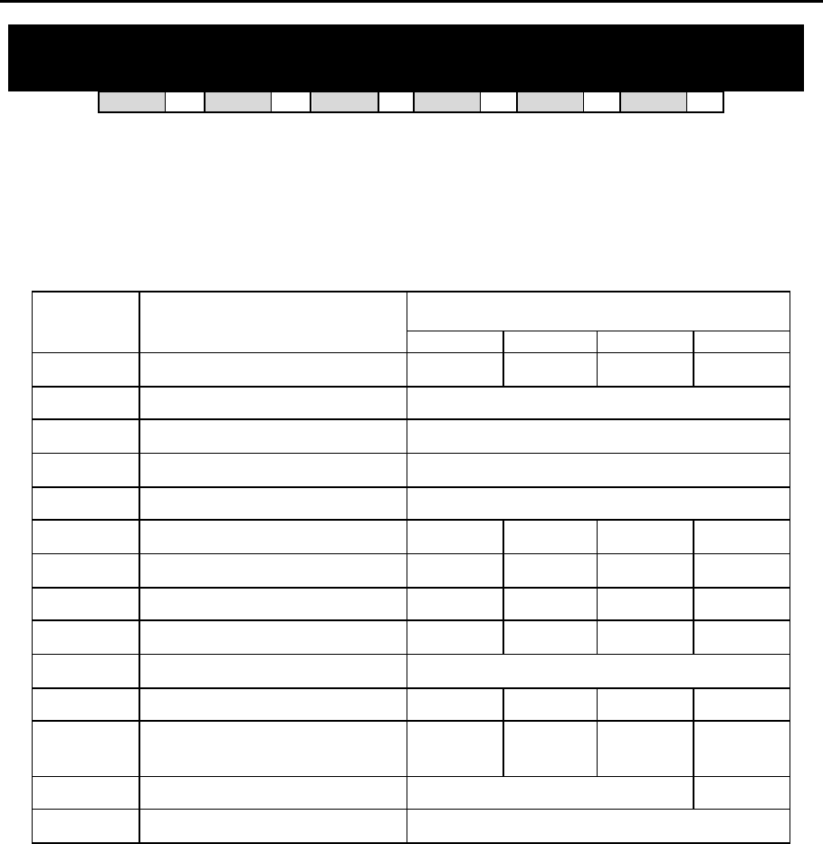
DCS MMC PROGRAMS
COMBINED PROGRAMMING MANUAL NOVEMBER 2001
MMC 107 (Page 1 of 2)
MMC: 107 KEY EXTENDER
DCS 33 CI 33 CII 33 816 33 408i 33 408 33
Used to view the programmable keys assigned to keyset stations. In addition, it allows the
system administrator to assign key extenders to those programmed keys which can have ex-
tenders, making general access feature keys more specific. For example, you may want to
set an SPD (Speed Dial) key to dial personal speed dial code 01 when selected. (Extenders
may also be entered in MMC 722 or 723 when programming key assignments.) The feature
keys that can have extenders are listed below.
EXTENDER
FEATURE
KEY FUNCTION
DCS CII 816 408/408i
BOSS Boss and Secretary 1–4 1–4 1–4 1–2
DIR Directory dial by name type 1–3
DP Direct Pick Up Extension or station group number
DS Direct Station Select Station number
FWRD Call Forward 0–5
GPIK Group Pick Up 01–20 01–20 01–08 01–04
IG In/Out Group 500–529 500–519 500–509 50–53
MMPG Meet Me Page 0–9, Q 0–9, Q 0–4, 5, Q 0–2, 5, Q
PAGE Page 0–9, Q 0–9, Q 0–4, 5, Q 0–2, 5, Q
PMSG Programmed Station Message 01–20
SG Station Group 500–529 500–519 500–509 50–53
SPD Speed Dial 00–49,
500–999 00–49,
500–999 00–49,
500–799 00–49,
500–699
SP UCD Supervisor UCD/ACD Group Number N/A
VT VM Transfer VM/AA Group Number
PROGRAM KEYS
UP & DOWN Used to scroll through options
KEYPAD Used to enter selections
SOFT KEYS Move cursor left and right
SPEAKER Used to store data and advance to next MMC
HOLD Used to clear previous entry

DCS MMC PROGRAMS
COMBINED PROGRAMMING MANUAL NOVEMBER 2001
MMC 107 (Page 2 of 2)
ACTION DISPLAY
1. Open programming and select 107
Display shows [201] EXT (MAST)
01:CALL1 →
OR OR
For 408 and 408i systems, display shows:
[21] EXT EXTEND
01:DT71 →
2. Dial station number (e.g., 205)
OR [205] EXT (MAST)
01:CALL1 →
Use UP or DOWN to scroll through station numbers
and press RIGHT soft key to move the cursor
3. Enter key number (e.g., 18)
OR [205] EXT (MAST)
18:DS → _
Press UP and DOWN to scroll through keys and use
RIGHT soft key to move the cursor
OR
Use above table to select desired extender
System will return to this step
205] EXT (MAST)
18:DS →DS207
4. Press TRSF to store and exit
OR
Press SPEAKER to store and advance to next MMC
Note: If the RIGHT soft key will not move the cursor to the right, you are attempting to add an extender to a key
that cannot have one (refer to the table, above, for allowed key extenders).
Default Data: None
Related Items: MMC 720 Copy Key Programming
MMC 721 Save Station Key Programming
MMC 722 Station Key Programming
MMC 723 System Key Programming
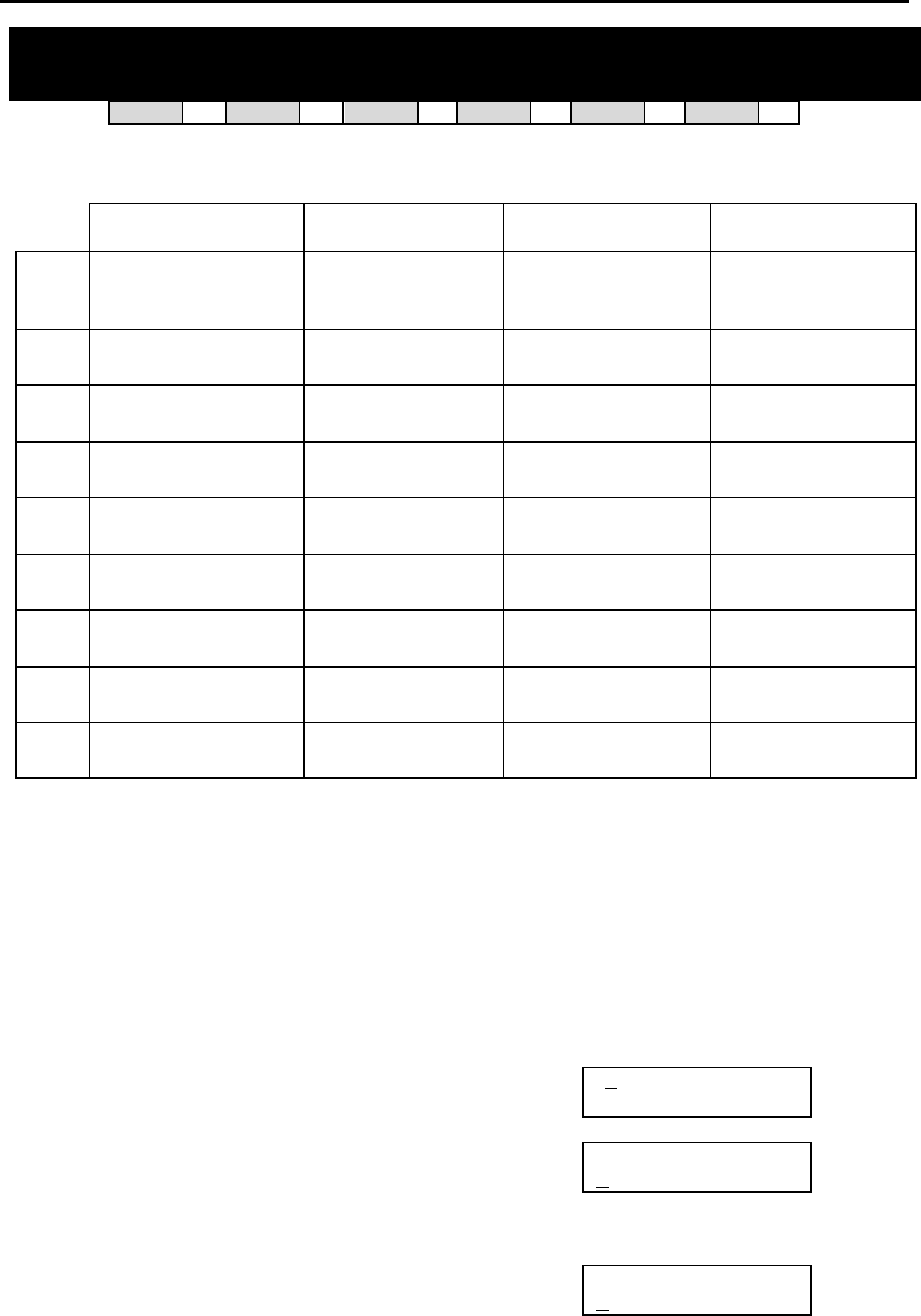
DCS MMC PROGRAMS
COMBINED PROGRAMMING MANUAL NOVEMBER 2001
MMC 108 (Page 1 of 2)
MMC: 108 STATION STATUS
DCS 33 CI 33 CII 33 816 33 408i 33 408 33
This is a read-only MMC. Displays the following attributes of a station port:
DCS Compact II 816 408 / 408i
0 PORT NO: #: Cabinet
(1–3)/Slot (1–7)/Port (1–
16)
PORT NO: Slot
(BASE, OSLI, MISC,
EX1–7)/Port (1–16)
PORT NO: 8DLI (01–
08) or 4SLI (01–04) PORT NO: 4DLI (01–
04) or 4SLI (01–04)
1 TENANT NUMBER: 1–2 TYPE: Type of phone
(e.g. 12B EU) TYPE: Type of phone
(e.g. 12B EU) TYPE: Type of phone
(e.g. 12B EU)
2 TYPE: Type of phone
(e.g. 12B, 24B) PICKUP GROUP:
None, 01–20 PICKUP GROUP:
None, 01–08 PICKUP GROUP:
None, 01–04
3 PICKUP GROUP: None,
01–20 SGR: Station Group
Number SGR: Station Group
Number SGR: Station Group
Number
4 SGR: Station Group
Number BOSS-SECR: None,
BOSS, SECR BOSS-SECR: None,
BOSS, SECR BOSS-SECR: None,
BOSS, SECR
5 BOSS-SECR: None,
BOSS, SECR PAGE: Page Zone
(None, 1–4, *) PAGE: Page Zone
(None, 1–4, *) PAGE: Page Zone
(None, 1–2)
6 PAGE: Page Zone
(None, 1–4, *) DAY COS NO: COS
(01–30) DAY COS NO: COS
(01–10) DAY COS NO: COS
(1–4)
7 DAY COS NO: COS
(01–30) NIGHT COS NO: COS
(01–30) NIGHT COS NO: COS
(01–10) NIGHT COS NO: COS
(1–4)
8 NIGHT COS NO: COS
(01–30) — — —
PROGRAM KEYS
UP & DOWN Used to scroll through options
KEYPAD Used to enter selections
SOFT KEYS Move cursor left and right
SPEAKER Used to advance to next MMC
ACTION DISPLAY
1. Open programming and select 108
Display shows first station (e.g. for Compact II) [201] STN STATUS
PORT NO:BASE01
2. Dial station number (e.g., 205)
OR [205] STN STATUS
PORT NO:EX1-01
Press UP or DOWN to select station and press RIGHT
soft key to move cursor
3. Dial 0–8 using table above to select station status
option [205] STN STATUS
PICKUP GROUP:01
OR
Press UP or DOWN to select status and press RIGHT
soft key to return to step 2

DCS MMC PROGRAMS
COMBINED PROGRAMMING MANUAL NOVEMBER 2001
MMC 108 (Page 2 of 2)
4. Press TRSF to exit
OR
Press SPEAKER to advance to next MMC
Default Data: Port No: Follows hardware position
Type: Follows phone type
Tenant Number: 1 (DCS only)
Pickup Group: 01
SGR: None
Boss–Secr: None
Page: None
Day COS No: 01 (or 1)
Night COS No: 01 (or 1)
Related Items: MMC 301 Assign Station COS
MMC 302 Pickup Groups
MMC 303 Assign Boss/Secretary
MMC 601 Assign Station Group
MMC 604 Assign Station to Page Zone
MMC 803 Assign Tenant Group (DCS only)
DCS MMC PROGRAMS
COMBINED PROGRAMMING MANUAL NOVEMBER 2001
MMC 109 (Page 1 of 1)
MMC: 109 DATE DISPLAY
DCS 33 CI 33 CII 33 816 33 408i 33 408 33
Allows the system administrator to select the date and time display mode on a per-station basis
or system-wide.
0 COUNTRY Sets overall display format and has two options:
0 = ORIENTAL MM/DD DAY HH:MM
1 = WESTERN DAY DD MON HH:MM
1 CLOCK Sets format of clock display and has two options:
0 = 12 HOUR Displays 1 P.M. as 01:00
1 = 24 HOUR Displays 1 P.M. as 13:00
2 DISPLAY Sets format of DAY and MONTH display and has two options:
0 = UPPER CASE Displays Friday as FRI and March as MAR
1 = LOWER CASE Displays Friday as Fri and March as Mar
PROGRAM KEYS
UP & DOWN Used to scroll through options
KEYPAD Used to enter selections
SOFT KEYS Move cursor left and right
SPEAKER Used to store data and advance to next MMC
HOLD Used to clear previous entry
ANS/RLS Used to select ALL
ACTION DISPLAY
1. Open programming and select 109
Display shows [201] DAY FORMAT
COUNTRY:WESTERN
2. Dial station number (e.g., 205)
OR [205] DAY FORMAT
COUNTRY:WESTERN
Press UP or DOWN to select station and press
RIGHT soft key to move cursor
OR
Press ANS/RLS for all keysets [ALL]DAY FORMAT
COUNTRY:?
3. Dial 0–2 to select option (e.g. Country)
OR [205] DAY FORMAT
COUNTRY:WESTERN
Press UP or DOWN to scroll through modes and
press RIGHT soft key to move cursor
4. Dial 0 or 1 to select option format (e.g. Oriental)
OR [205] DAY FORMAT
COUNTRY:ORIENTAL
Press UP or DOWN to select format and
press RIGHT soft key to return to step 2
5. Press TRSF to store and exit
OR
Press SPEAKER to store and advance to next MMC
Default Data: Country: Western
Clock: 24 hour
Display: Lowercase
Related Items: MMC 505 Assign Date and Time

DCS MMC PROGRAMS
COMBINED PROGRAMMING MANUAL NOVEMBER 2001
MMC 110 (Page 1 of 2)
MMC: 110 STATION ON/OFF
DCS 33 CI 33 CII 33 816 33 408i 33 408 33
Allows the system administrator to set any of the following keyset features.
AUTO HOLD Automatically places an existing C.O. call on hold if a CALL key,
trunk key or trunk route key is pressed during that call.
AUTO TIMER Automatically starts the stopwatch timer during a C.O. call. (CALL
COST option, below, should be OFF for this feature to work.)
HEADSET USE When ON, this feature disables the hookswitch allowing a headset
user to answer all calls by pressing the ANS/RLS key.
HOT KEYPAD When ON, this feature allows the user to dial numbers on the keypad
without having to first lift the handset or press the SPEAKER key.
KEY TONE Allows the user to hear a slight tone when pressing keys on the key-
set.
PAGE REJOIN Allows the user to hear the latter part of page announcements if the
keyset becomes free during a page.
RING PREFER When OFF, requires the user to press the fast flashing button to an-
swer a ringing call after lifting the handset.
CALL COST If enabled (ON), LCD shows real-time call cost based on Metering
Pulses arrived. (See AUTO TIMER option.)
AME BGM Determines whether a station using Answering Machine Emulation
will hear their personal greeting or background music (BGM) while
callers are listening to the personal greeting. A BGM source must be
selected for this to work. (Cadence and SVMi-4 voice mail systems
only.)
AME PSWD Sets the Answering Machine Emulation password ON or OFF. (Ca-
dence and SVMi-4 voice mail systems only.)
NOT CONT.CID When ON, the keyset displays the call timer for the duration of an in-
coming trunk call (if AUTO TIMER is ON). When OFF, the CLIP num-
ber for a call is displayed for the duration of the call. (Not applicable
to 408 systems.)
Note: Keyset users can set or change these options for their own keyset (refer to the Samsung DCS Keyset
User Guide for details).
PROGRAM KEYS
UP & DOWN Used to scroll through options
KEYPAD Used to enter selections
SOFT KEYS Move cursor left and right
SPEAKER Used to store data and advance to next MMC
HOLD Used to clear previous entry
ANS/RLS Used to select ALL

DCS MMC PROGRAMS
COMBINED PROGRAMMING MANUAL NOVEMBER 2001
MMC 110 (Page 2 of 2)
ACTION DISPLAY
1. Open programming and select 110
Display shows [201] STN ON/OFF
AUTO HOLD :OFF
2. Dial station number (e.g., 205)
OR [205] STN ON/OFF
AUTO HOLD :OFF
Press UP or DOWN to select keyset and press
RIGHT soft key to move cursor
OR
Press ANS/RLS for ALL [ALL] STN ON/OFF
AUTO HOLD :?
3. Press UP or DOWN to select option and
press RIGHT soft key to move cursor [205] STN ON/OFF
HOT KEYPAD : ON
4. Dial 1 for ON or 0 for OFF
OR [205] STN ON/OFF
HOT KEYPAD :OFF
Press UP or DOWN to select ON or OFF and
press LEFT or RIGHT soft key to return to step 3
5. Press TRSF to store and exit
OR
Press SPEAKER to store and advance to next MMC
Default Data: Auto Hold Off
Auto Timer On
Headset Use Off
Hot Keypad On
Key Tone On
Page Rejoin On
Ring Pref On
Call Cost Off
Not Cont.CID Off
AME BGM Off
AME PSWD Off
Related Items: MMC 301 Assign Station COS
MMC 701 Assign COS Contents
DCS MMC PROGRAMS
COMBINED PROGRAMMING MANUAL NOVEMBER 2001
MMC 111 (Page 1 of 1)
MMC: 111 KEYSET RING TONE
DCS 33 CI 33 CII 33 816 33 408i 33 408 33
Allows the system administrator to select the ring tone heard at each keyset. There are eight (1–
8) ring tones available. A short tone burst of the selection will be heard when a key is pressed.
PROGRAM KEYS
UP & DOWN Used to scroll through options
KEYPAD Used to enter selections
SOFT KEYS Move cursor left and right
SPEAKER Used to store data and advance to next MMC
HOLD Used to clear previous entry
ANS/RLS Used to select ALL
ACTION DISPLAY
1. Open programming and select 111
Display shows [201] RING TONE
SELECTION 5
2. Dial keyset number (e.g., 205)
OR [205] RING TONE
SELECTION 5
Press UP or DOWN to select station and press
RIGHT soft key to move cursor
OR
Press ANS/RLS to select All [ALL] RING TONE
SELECTION ?
3. Dial 1–8 to select ring tone
OR [205] RING TONE
SELECTION 6
Press UP or DOWN to select ring tone and press
RIGHT soft key to move cursor
4. Press TRSF to store and exit
OR
Press SPEAKER to store and advance to next MMC
Default Data: SELECTION 5
Related Items: MMC 114 Station Volume
DCS MMC PROGRAMS
COMBINED PROGRAMMING MANUAL NOVEMBER 2001
MMC 112 (Page 1 of 1)
MMC: 112 ALARM REMINDER
DCS 33 CI 33 CII 33 816 33 408i 33 408 33
Allows the system administrator to set or change the alarm clock/appointment reminder feature
for any station. Keyset users can set their own alarms. A number of alarms may be set for each
station: three (1–3) for DCS systems or two (1–2) for Compact II, 816 and 408/408i systems.
Each alarm may be defined as a one-time or TODAY alarm, or as a DAILY alarm, or NOTSET as
described below. The TODAY alarm is automatically cancelled after it rings, while the DAILY
alarm rings every day at the same time.
Dial 0: NOTSET Dial 1: TODAY Dial 2: DAILY
PROGRAM KEYS
UP & DOWN Used to scroll through options
KEYPAD Used to enter selections
SOFT KEYS Move cursor left and right
SPEAKER Used to store data and advance to next MMC
HOLD Used to clear previous entry
ACTION DISPLAY
1. Open programming and select 112
Display shows [201] ALM CLK(1)
HHMM: èNOTSET
2. Dial station number (e.g., 205)
OR [205] ALM CLK(1)
HHMM: èNOTSET
Press UP or DOWN to select station and
press RIGHT soft key to move cursor
3. Dial alarm number (e.g., 2)
OR [205] ALM CLK(2)
HHMM: èNOTSET
Press UP or DOWN to select alarm and
press RIGHT soft key to move cursor
OR
Press LEFT soft key to return to step 2
4. Enter alarm time in 24-hour clock format
(e.g., 1300) [205] ALM CLK (2)
HHMM:1300èNOTSET
Display will automatically advance to step 5
5. Dial valid entry from above list for alarm type (e.g. 2,
DAILY) [205] ALM CLK (2)
HHMM:1300èDAILY
OR
Press UP or DOWN to select alarm type
and press RIGHT soft key to move cursor and
return to step 2
6. Press TRSF to store and exit
OR
Press SPEAKER to store and advance to next MMC
Default Data: Alarms set to NOTSET
Related Items: None
DCS MMC PROGRAMS
COMBINED PROGRAMMING MANUAL NOVEMBER 2001
MMC 113 (Page 1 of 1)
MMC: 113 VIEW MEMO NUMBER
DCS 33 CI 33 CII 33 816 33 408i 33 408 33
Allows the system administrator to enter memos on stations. Up to three memos can be entered,
depending on your system. MMC 116 (Alarm and Message) can be programmed to remind the
station user to read the memo(s).
Each memo can be up to 13 characters long and is entered using the dial keypad. For example,
press “6” once to enter the letter ”M”, and press ”3” twice for an ”E”. Continue selecting charac-
ters from the keypad to complete the memo. Press the programmable ”A” key to toggle between
upper and lower case text.
Tip: When the character you want is on the same key as the previous character you typed in, press the UP
key to move the cursor to the right, then select the character.
The # key can be used for the following special characters (in sequence of key presses):
#
space
& ! : ? . , % $ - < > / =
[ ] @ ^ ( ) _ + { } | ; " → `
PROGRAM KEYS
KEYPAD Used to enter selections
SOFT KEYS Move cursor left and right
SPEAKER Used to store data and advance to next MMC
HOLD Used to clear previous entry
“A” Key #19 (24B keyset) or key #7 (12B keyset) or key #1 (6B keyset)
toggles uppercase and lowercase text.
ACTION DISPLAY
1. Open programming and select 113
Display shows [201] VIEW MEMO
1:
2. Dial the station number (e.g., 205)
OR [205] VIEW MEMO
1:
Press UP or DOWN to select station and
press RIGHT soft key to move cursor
3. Dial memo number (1–3)
OR [205] VIEW MEMO
1:_
Press UP or DOWN to select and press RIGHT soft
key to move cursor
4. Press RIGHT soft key to move cursor and add
memo via dial keypad using above procedure [205] VIEW MEMO
1:CALL TOM
5. Press TRSF to store and exit
OR
Press SPEAKER to store and advance to next MMC
Default Data: None
Related Items: MMC 116 Alarm and Message
DCS MMC PROGRAMS
COMBINED PROGRAMMING MANUAL NOVEMBER 2001
MMC 114 (Page 1 of 1)
MMC: 114 STATION VOLUME
DCS 33 CI 33 CII 33 816 33 408i 33 408 33
Allows the system administrator to set volume levels for keysets.
0 RING VOLUME Set a level for ring volume. There are eight volume levels: level 1 is
the lowest and level 8 the highest.
1 OFF-RING VOL Set a level for off-hook ring volume. There are eight volume levels:
level 1 is the lowest and level 8 the highest.
2 HANDSET VOL Set a level for listening volume through handset. There are eight vol-
ume levels: level 1 is the lowest and level 8 the highest.
3 SPEAKER VOL Set a level for listening volume through speaker. There are 16 vol-
ume levels: level 1 is the lowest and level 16 the highest.
4 BGM VOLUME Set a level for background music volume. There are 16 volume lev-
els: level 1 is the lowest and level 16 the highest.
PROGRAM KEYS
UP & DOWN Used to scroll through options
KEYPAD Used to enter selections
SOFT KEYS Move cursor left and right
SPEAKER Used to store data and advance to next MMC
ANS/RLS Used to select ALL
ACTION DISPLAY
1. Open programming and select 114
Display shows
[201] STN VOLUME
RING VOLUME : 4
2. Dial station number (e.g. 205)
[205] STN VOLUME
RING VOLUME : 4
3. Dial option number
OR
Press UP or DOWN to select option and press
RIGHT soft key
[205] STN VOLUME
OFF-RING VOL: 4
4. Dial volume level using keypad (you will hear a brief tone
for the level you select) and system returns to step 3
OR
Press UP or DOWN to select volume (you will hear a brief
tone for each level) and press RIGHT soft key to return to
step 3
[205] STN VOLUME
OFF-RING VOL: 3
5. Press TRSF to store and exit
OR
Press SPEAKER to store and advance to next MMC
Default Data: Ring Volume 4
Off-Hook Ring Volume 4
Handset Volume 4
Speaker Volume 13
BGM Volume 13
Related Items: MMC 111 Keyset Ring Tone
DCS MMC PROGRAMS
COMBINED PROGRAMMING MANUAL NOVEMBER 2001
MMC 115 (Page 1 of 1)
MMC: 115
SET PROGRAMMED MESSAGE
DCS 33 CI 33 CII 33 816 33 408i 33 408 33
Allows the system administrator to set a programmed message at individual or all keysets. There
are 20 messages available (01–20). These messages are as set up in MMC 715, Programmed
Station Message.
PROGRAM KEYS
UP & DOWN Used to scroll through options
KEYPAD Used to enter selections
SOFT KEYS Move cursor left and right
SPEAKER Used to store data and advance to next MMC
HOLD Used to clear previous entry
ANS/RLS Used to select ALL
ACTION DISPLAY
1. Open programming and select 115
Display shows [201] PGMMSG(00)
CANCEL PGM MSG
2. Dial station number (e.g., 205)
OR [205] PGMMSG(00)
CANCEL PGM MSG
Press UP or DOWN to select station and press RIGHT
soft key to move cursor
OR
Press ANS/RLS to select All [ALL] PGMMSG(??)
3. Dial 01–20 to select message number (e.g., 05)
OR [205] PGMMSG(05)
PAGE ME
Press UP or DOWN to select message and press RIGHT
soft key to return to step 2
OR
Select 00 to cancel a previously set message
4. Press TRSF to store and exit
OR
Press SPEAKER to store and advance to next MMC
Default Data: No messages selected
Related Items: MMC 715 Programmed Station Message
MMC 722 Station Key Programming
MMC 723 System Key Programming
DCS MMC PROGRAMS
COMBINED PROGRAMMING MANUAL NOVEMBER 2001
MMC 116 (Page 1 of 2)
MMC: 116 ALARM AND MESSAGE
DCS 33 CI 33 CII 33 816 33 408i 33 408 33
Allows the system administrator or technician to set or change the alarm clock/appointment re-
minder feature for individual or all stations. For DCS systems, three alarms (1–3) can be set
for each station. For other systems, two alarms (1–2) can be set. Each alarm may be defined
as a one-time or TODAY alarm, as a DAILY alarm, or NOTSET as described below. The TODAY
alarm is automatically cancelled after it rings, while the DAILY alarm rings every day at the same
time. It is also possible to set a message to display when the alarm is sounded.
Dial Alarm Type
0 NOTSET
1 TODAY
2 DAILY
Messages are written using the keypad. Each key press selects a character and moves the cur-
sor to the next position. For example, if the message is “MEETING”, press the number “6” once
to get the letter “M”. Now press the number “3” twice to get the letter “E” Continue selecting
characters from the keypad to complete your message. Press the programmable “A” key to tog-
gle between upper and lower case text.
Tip: When the character you want is on the same key as the previous character you typed in, press the UP
key to move the cursor to the right, then select the character.
The # key can be used for the following special characters (in sequence of key presses):
#
space
& ! : ? . , % $ - < > / =
[ ] @ ^ ( ) _ + { } | ; " → `
PROGRAM KEYS
UP & DOWN Used to scroll through options
KEYPAD Used to enter selections
SOFT KEYS Move cursor left and right
SPEAKER Used to store data and advance to next MMC
HOLD Used to clear previous entry
“A” Key #19 (24B keysets) or key #7 (12B keysets) or key #1 (6B key-
sets) toggles upper case and lower case text.
DCS MMC PROGRAMS
COMBINED PROGRAMMING MANUAL NOVEMBER 2001
MMC 116 (Page 2 of 2)
ACTION DISPLAY
1. Open programming and select 116
Display shows [201] ALM REM(1)
HHMM: èNOTSET
2. Dial station number (e.g., 205)
OR [205] ALM REM(1)
HHMM: èNOTSET
Press UP or DOWN to select station and press RIGHT
soft key to move cursor
OR
Press ANS/RLS to select all stations [ALL] ALM REM(1)
HHMM: èNOTSET
3. Dial alarm number (e.g., 2)
OR [205] ALM REM(2)
HHMM: èNOTSET
Press UP or DOWN to select alarm and press RIGHT
soft key to move cursor
4. Enter alarm time in 24-hour clock format
(e.g., 1300 for 1pm) [205] ALM REM(2)
HHMM:1300èNOTSET
Display will automatically advance to step 5
5. Dial valid entry from above list for alarm type (e.g. 2,
DAILY) [205] ALM REM(2)
HHMM:1300èDAILY
OR
Press UP or DOWN to select alarm type and press
RIGHT soft key to move cursor
6. Enter message using above method and press RIGHT
soft key to return to step 2 [205] ALM REM(2)
Meeting
7. Press TRSF to store and exit
OR
Press SPEAKER to store and advance to next MMC
Default Data: Alarms set to NOTSET
Related Items: None
DCS MMC PROGRAMS
COMBINED PROGRAMMING MANUAL NOVEMBER 2001
MMC 119 (Page 1 of 1)
MMC: 119 SET CLIP DISPLAY
DCS 33 CI 33 CII 33 816 33 408i 33 408 77
Allows the system administrator or keyset user to change the order in which CLIP information is
displayed on a keyset LCD. CLIP display options are as follows:
0 NO DISPLAY No CLIP data is displayed.
1 NUMBER FIRST CLIP number received from central office is displayed first.
2 NAME FIRST CLIP name is displayed first (if set in MMC 728)
PROGRAM KEYS
UP & DOWN Used to scroll through options
KEYPAD Used to enter selections
SPEAKER Save data and advance to next MMC
ANS/RLS Used to select ALL
ACTION DISPLAY
1. Open programming and select 119
Display shows [201] CLIP DISP.
NAME FIRST
2. Enter station number (e.g. 204)
OR
Press UP or DOWN to scroll through stations and
press RIGHT soft key to select a station
OR
[204] CLIP DISP.
NAME FIRST
Press ANS/RLS to select ALL
[ALL] CLIP DISP.
?
3. Dial display option 0, 1 or 2 (e.g. 1)
Press UP or DOWN to select option and press
RIGHT or LEFT soft key to return to step 2
[204] CLIP DISP.
NUMBER FIRST
4. Press TRSF to store and exit
OR
Press SPEAKER to save and advance to next MMC
Default Data : NAME FIRST
Related Items: MMC 728 CLIP Translation Table
DCS MMC PROGRAMS
COMBINED PROGRAMMING MANUAL NOVEMBER 2001
MMC 121 (Page 1 of 1)
MMC: 121 KEYSET LANGUAGE
DCS 33 CI 77 CII 33 816 33 408i 33 408 33
Used to assign an LCD display based on a keyset user’s own language. Options include some or
all of the following, depending on your system:
ENGLISH
GERMAN
PORTUGAL
NORSK (NORWAY)
DANISH
DUTCH
ITALY
SPANISH
PROGRAM KEYS
UP & DOWN Used to scroll through options
KEYPAD Used to enter selections
SOFT KEYS Move cursor left and right
SPEAKER Used to store data and advance to next MMC
HOLD Used to clear previous entry
ANS/RLS Used to select ALL
ACTION DISPLAY
1. Open programming and select 121
Display shows
[201] LANGUAGE
ENGLISH
2. Dial keyset number (e.g., 205)
OR
Press UP or DOWN to select keyset and press RIGHT
soft key
OR
Press ANS/RLS to select All
[205] LANGUAGE
ENGLISH
[ALL] LANGUAGE
?
3. Press UP or DOWN to select language and press
RIGHT soft key.
[205] LANGUAGE
GERMAN
4. Press TRSF to store and exit
OR
Press SPEAKER to store and advance to next MMC
Default Data: ENGLISH
Related Items: Multi-Language
DCS MMC PROGRAMS
COMBINED PROGRAMMING MANUAL NOVEMBER 2001
MMC 200 (Page 1 of 1)
MMC: 200 OPEN CUSTOMER
PROGRAMMING
DCS 33 CI 33 CII 33 816 33 408i 33 408 33
Used to open (enable) or close (disable) customer-level programming by the system administra-
tor. If programming is not opened and an attempt is made to access a customer-level MMC, the
error message [NOT PERMIT] will be displayed. A four-digit passcode is required to enable cus-
tomer programming (which can be changed in MMC 201, if required). Each digit can be 0–9.
When opened, this MMC allows access to all MMCs specified by the system installer in MMC
802, Customer Access MMC Number.
PROGRAM KEYS
UP & DOWN Select open or closed
KEYPAD Used to enter passcode
SPEAKER Save data and advance to next MMC
TRSF Exit Programming
ACTION DISPLAY
1. Press TRSF 200
Display shows ENABLE CUS.PROG.
PASSCODE:_
2. Enter passcode ENABLE CUS.PROG.
PASSCODE: ∗∗∗∗
Correct code shows
ENABLE CUS.PROG.
DISABLE
Incorrect code shows ENABLE CUS.PROG.
PASSWORD ERROR
3. Dial 1 for ENABLE or 0 for DISABLE
OR
Press UP or DOWN arrow key to select ENABLE or
DISABLE and press RIGHT soft key
ENABLE CUS.PROG.
ENABLE
4. Press SPEAKER to advance to MMC entry level and
press UP or DOWN key to select MMC (e.g. 212)
OR
212:ALARM RING
SELECT PROG. ID
Enter MMC number and press RIGHT soft
key to enter MMC
5. Press TRSF key to exit
Default Data: DISABLE (closed)
Passcode=1234
Related Items: MMC 201 Change Customer Passcode
MMC 501 System-Wide Timers
MMC 802 Customer Access MMC Number
DCS MMC PROGRAMS
COMBINED PROGRAMMING MANUAL NOVEMBER 2001
MMC 201 (Pages 1 of 1)
MMC: 201 CHANGE CUSTOMER
PASSCODE
DCS 33 CI 33 CII 33 816 33 408i 33 408 33
Used to change the passcode allowing access to MMC 200, Open Customer Programming, from
its current value.
PROGRAM KEYS
KEYPAD Used to enter passcodes
SPEAKER Save data and advance to next MMC
ACTION DISPLAY
1. Open programming and select 201
CUST. PASSCODE
NEW CODE:_
2. Enter new passcode via dial keypad (maximum four
digits) CUST. PASSCODE
NEW CODE: QQQQ
3. Verify new passcode via dial keypad CUST. PASSCODE
VERIFY : QQQQ
PASSCODE verify successful
(go to step 4) CUST. PASSCODE
VERIFY :SUCCESS
OR
PASSCODE verify failure
(return to step 2) CUST. PASSCODE
VERIFY :FAILURE
4. Press TRSF to store and exit
OR
Press SPEAKER to store and advance to
next MMC
Default Data: Passcode = 1234
Related Items: MMC 200 Open Customer Programming
DCS MMC PROGRAMS
COMBINED PROGRAMMING MANUAL NOVEMBER 2001
MMC 202 (Pages 1 of 1)
MMC: 202 CHANGE FEATURE
PASSCODES
DCS 33 CI 77 CII 33 816 33 408i 33 408 33
Your system supports some or all of the following features:
DAY/NIGHT
DISA ALARM
ALARM CLR
AA RECORD
DECT (BSI) REGISTER
This MMC is used to change the passcode for supported features
Note: The passcode is four digits long. Each digit can be 0–9.
PROGRAM KEYS
UP & DOWN Used to scroll through options
KEYPAD Used to enter passcodes
SPEAKER Save data and advance to next MMC
ACTION DISPLAY
1. Open programming and select 202
Display shows CHANGE PASSCODE
DAY/NIGHT :0000
2. Press UP or DOWN key to make selection
Press RIGHT soft key to move cursor to passcode entry CHANGE PASSCODE
ALARM CLR :8765
3. Enter new passcode via digits from
dial keypad CHANGE PASSCODE
ALARM CLR :9999
Press RIGHT soft key to return to step 2
Continue to change other passcodes
4. Press TRSF to store and exit
OR
Press SPEAKER to store and advance to
next MMC
Default Data: DAY/NIGHT 0000
DISA ALARM 5678
ALARM CLR 8765
AA RECORD 4321
DECT REGISTER 4321
Related Items: MMC 212 Alarm Ringing Station
MMC 214 DISA Alarm Ringing Station
MMC 410 Assign DISA Trunk
MMC 507 Assign Auto Night Time
MMC 737 DECT System Code
MMC 744 BSI Registration On/Off
DCS MMC PROGRAMS
COMBINED PROGRAMMING MANUAL NOVEMBER 2001
MMC 203 (Pages 1 of 1)
MMC: 203 ASSIGN UA DEVICE
DCS 33 CI 33 CII 33 816 33 408i 33 408 33
Assigns the ringing device to be accessed when a Universal Answer (UA) key is pressed or the
UA pickup code is dialled. UA assignment is made in MMC 601, Assign Station Group, for a
group and then the group is entered here. The UA device can be one of the device types listed
below. The device type is automatically determined by the directory number (DN) entered.
DIRECTORY NUMBER (DN)
DCS CII 816 408/408i
DEVICE TYPE DESCRIPTION
201–349 201–308 201–216 21–28 STATION The UA device is a keyset
or SLT.
3601–3602 361–365 361–362 361 RING PAGE Ring over page.
500–529 500–519 500–509 50–53 STATION
GROUP The UA device is a station
group.
Note: Only one of the above options can be selected. If the ability to ring more than one item (e.g., all four
external page zones) is required, a station group containing all four zone codes must be created.
PROGRAM KEYS
UP & DOWN Used to scroll through options
KEYPAD Used to enter DN of selected device
SPEAKER Used to store data and advance to next MMC
HOLD Used to clear previous entry
ACTION DISPLAY
1. Open programming and select 203
Display shows current assignment ASSIGN UA PORT
NONE-NO UA
2. Dial DN of UA device (e.g., 205)
OR ASSIGN UA PORT
205 -STATION
Use UP and DOWN keys to scroll through
available devices
3. Press TRSF to store and exit
OR
Press SPEAKER to store and advance to next MMC
Default Data: None
Related Items: MMC 204 Common Bell Control
MMC 219 Common Relay Service Type
MMC 601 Assign Station Group
MMC 605 Assign External Page Zone
DCS MMC PROGRAMS
COMBINED PROGRAMMING MANUAL NOVEMBER 2001
MMC 204 (Page 1 of 1)
MMC: 204 COMMON BELL CONTROL
DCS 33 CI 33 CII 33 816 33 408i 33 408 33
Determines whether the common bell relay contacts have an interrupted or continuous closure
when activated. If interrupted is chosen, the relay follows an internal ring pattern of one second
closed followed by three seconds open.
By default, all common bell relay pairs are assigned as:
DCS: 380x
Compact II: 363–365
816: 362
408 and 408i: 361
PROGRAM KEYS
UP & DOWN Used to scroll through options
KEYPAD Used to enter selections
SOFT KEYS Move cursor
SPEAKER Used to store data and advance to next MMC
ACTION DISPLAY
1. Open programming and select 204
Display shows current setting [3801]COM. BELL
CONTINUOUS
(Note: Display differs according to system) OR
[363] COM/LD BELL
CONTINUOUS
2. Dial common bell number
OR
Press UP or DOWN key to make selection of
common bell numbers and press RIGHT soft key to
advance cursor
3. Dial 0 for continuous or 1 for interrupted operation
OR
Use UP or DOWN to scroll through options
Press RIGHT soft key to return to step 2
[3801]COM. BELL
INTERRUPTED
OR
[363] COM/LD BELL
INTERRUPTED
4. Press TRSF to store and exit
OR
Press SPEAKER to store and advance to next MMC
Default Data: Continuous
Related Items: MMC 203 Assign UA Device
MMC 219 Common Relay Service Type
MMC 601 Assign Station Group
DCS MMC PROGRAMS
COMBINED PROGRAMMING MANUAL NOVEMBER 2001
MMC 205 (Page 1 of 1)
MMC: 205 ASSIGN LOUD BELL
DCS 33 CI 77 CII 33 816 33 408i 33 408 33
Designates the station that controls the loud bell ring output of one of the following:
DCS systems—a Trunk A card. Each Trunk A card has one loud bell output; these outputs are
given a Directory Number of 3901–3920 as a default value to enable them to be assigned.
Compact II systems—a Misc card (assigned in MMC 219, Common Relay Service Type).
816 and 408/408i systems—a base board (assigned in MMC 219, Common Relay Service
Type).
The loud bell will follow the ring cadence of the designated station. Only a station can be as-
signed to control the loud bell; a station group cannot be assigned.
PROGRAM KEYS
UP & DOWN Used to scroll through options
KEYPAD Used to enter selections
SOFT KEYS Move cursor left and right
SPEAKER Used to store data and advance to next MMC
HOLD Clears previous entry
ACTION DISPLAY
1. Open programming and select 205
Display shows current setting
[361] LOUD BELL
RING PAIR : NONE
2. Dial loud bell number (e.g., 362)
OR
Use UP or DOWN to scroll through loud bell
numbers and press RIGHT soft key to move the cursor
[362] LOUD BELL
RING PAIR : NONE
3. Enter station number (e.g., 201)
OR
Press UP or DOWN key to make selection and
press RIGHT soft key to return to step 2
[362] LOUD BELL
RING PAIR :201
4. Press TRSF to store and exit
OR
Press SPEAKER to store and advance to next MMC
Default Data: NONE (Unassigned)
Related Items: MMC 219 Common Relay Service Type
DCS MMC PROGRAMS
COMBINED PROGRAMMING MANUAL NOVEMBER 2001
MMC 206 (Page 1 of 1)
MMC: 206 BARGE-IN TYPE
DCS 33 CI 33 CII 33 816 33 408i 33 408 33
The Barge In feature allows selected keysets to intrude on other keysets which are not set as se-
cure from barge in. This MMC sets the type of barge-in that is permitted.
DIAL TYPE OF BARGE-IN DESCRIPTION
0 NO BARGE IN Barge-in feature is unavailable regardless of a sta-
tion’s barge-in status.
1 WITH TONE Barge-in will have an intrusion tone and display at
the barged-in on station.
2 WITHOUT TONE There is no barge-in tone or display at the barged-in
on station and the barging-in station will be muted.
PROGRAM KEYS
UP & DOWN Used to scroll through options
KEYPAD Used to enter selections
SOFT KEYS Move cursor left and right
SPEAKER Used to store data and advance to next MMC
ACTION DISPLAY
1. Open programming and select 206
Display shows
BARGE IN TYPE
NO BARGE IN
2. Dial 0–2 to select barge-in type (e.g., 2)
OR
Press UP or DOWN to select barge-in type
and press RIGHT soft key
BARGE IN TYPE
WITHOUT TONE
3. Press TRSF to store and exit
OR
Press SPEAKER to store and advance to next MMC
Default Data: NO BARGE IN
Related Items: MMC 301 Assign Station COS
MMC 701 Assign COS Contents
DCS MMC PROGRAMS
COMBINED PROGRAMMING MANUAL NOVEMBER 2001
MMC 207 (Page 1 of 1)
MMC: 207 ASSIGN VM/AA PORT
DCS 33 CI 33 CII 33 816 33 408i 33 408 33
Enables SLI ports to be designated as NORMAL or VMAA. VMAA ports receive digits designated
in MMC 726, VM/AA Options, and also receive a true disconnect signal upon completion of a call.
Do not make VMAA ports data; this will return them to a single line port and stop voice mail inte-
gration. VMAA ports have the equivalent of data protect written in the program and are protected
against tones.
PROGRAM KEYS
UP & DOWN Used to scroll through options
KEYPAD Used to enter selections
SOFT KEYS Move cursor left and right
SPEAKER Used to store data and advance to next MMC
HOLD Used to clear previous entry
ANS/RLS Used to select ALL
ACTION DISPLAY
1. Open programming and select 207
Display shows
[209] VMAA PORT
NORMAL PORT
2. Dial station number (e.g., 205)
OR
Press UP or DOWN to select station
and press RIGHT soft key to move cursor
[205] VMAA PORT
NORMAL PORT
3. Dial 1 or 0 to select port type (1=VMAA, 0=NORMAL)
OR
Press UP or DOWN to select option and press
RIGHT soft key
[205] VMAA PORT
VMAA PORT
4. Press TRSF to store and exit
OR
Press SPEAKER to store and advance to next MMC
Default Data: NORMAL PORT
Related Items: MMC 601 Assign Station Group
MMC 726 VM/AA Options

DCS MMC PROGRAMS
COMBINED PROGRAMMING MANUAL NOVEMBER 2001
MMC 208 (Page 1 of 1)
MMC: 208 ASSIGN RING TYPE
DCS 33 CI 33 CII 33 816 33 408i 33 408 33
Provides the flexibility to program SLTs to have ICM ringing, C.O. ringing and data secure. With
the many types of external ringing devices, all configurations can be met. DATA RING also has a
positive disconnect signal. Do not make VM/AA ports data; this will return them to a single line
port and stop voice mail integration.
OPTIONS
0 ICM RING
1 C.O. RING
2 DATA RING
PROGRAM KEYS
UP & DOWN Used to scroll through options
KEYPAD Used to enter selections
SOFT KEYS Move cursor left and right
SPEAKER Used to store data and advance to next MMC
HOLD Used to clear previous entry
ANS/RLS Used to select ALL
ACTION DISPLAY
1. Open programming and select 208
Display shows
[209] RING TYPE
ICM RING
2. Dial SLT station number (e.g., 205)
OR
Press UP or DOWN to select station and
press RIGHT soft key to move cursor
[205] RING TYPE
ICM RING
3. Dial 0, 1 or 2 to select port type (e.g. 2)
OR
Press UP or DOWN to select option and press
LEFT or RIGHT soft key to return to step 2 above
[205] RING TYPE
DATA RING
4. Press TRSF to store and exit
OR
Press SPEAKER to store and advance to next MMC
Default Data: ICM RING
Related Items: None
DCS MMC PROGRAMS
COMBINED PROGRAMMING MANUAL NOVEMBER 2001
MMC 209 (Page 1 of 1)
MMC: 209 ASSIGN ADD-ON MODULE
DCS 33 CI 33 CII 33 816 33 408i 77 408 77
Designates to which station an add-on module (AOM) is assigned.
PROGRAM KEYS
UP & DOWN Used to scroll through options
KEYPAD Used to enter selections
SOFT KEYS Move cursor left and right
RELEASE Used to store data and advance to next MMC
HOLD Clears previous entry
ACTION DISPLAY
1. Open programming and select 209
Display shows first AOM
[301] AOM MASTER
MASTER:NONE
2. Dial AOM number
OR
Press UP or DOWN to scroll through AOM numbers
and press RIGHT soft key to move the cursor
[301] AOM MASTER
MASTER:NONE
3. Enter station number, (e.g., 201)
OR
Press UP or DOWN to select station numbers
[301] AOM MASTER
MASTER:201
4. Press TRSF to store and exit
OR
Press SPEAKER to store and advance to next MMC
Default Data: MASTER = NONE
Related Items: None
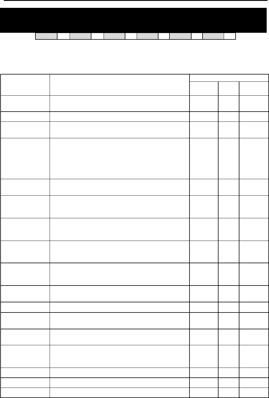
DCS MMC PROGRAMS
COMBINED PROGRAMMING MANUAL NOVEMBER 2001
MMC 210 (Page 1 of 2)
MMC: 210 CUSTOMER ON/OFF
DCS 33 CI 33 CII 33 816 33 408i 33 408 33
Allows the system administrator to set system features on or off. Not all features are available on
all systems. Refer to the following table for details (a tick means “available”).
SYSTEM
FEATURE
DESCRIPTION DCS / C II 816 408/408i
DISA PSWD Determines whether outside customers are required to
enter DISA passcode (Yes=ON, No=OFF). 33 33 33
LCR ENABLE Enables LCR feature in the system. 33 33 33
SMDI VMS SET Allows SMDI integration through RS-232 port for the ex-
ternal PC-based Voice Mail system 33 7 7
PERI UCD SET Periodic UCD information provider. Enables UCD statis-
tics data on a per UCD group basis to print out on the I/O
port which has been set as SMDR or UCD REPT in real
time (see MMC 501- PERI UCD REPORT timer option).
This allows extended manipulation of the information by
an external third-party-provided software package.
33 33 7
CID CODE INS Allows the digit ‘1’ to be automatically inserted for a toll
call. (Not used in UK.) 33 33 408i only
DISA MOH An additional option that can be presented to outside
DISA callers: a variable indication provided by an MOH
source instead of a fixed DISA dial tone. 33 33 33
TRANSFER MOH Callers who have been transferred from an extension or
UCD group or AA group will hear MOH, until answered
by the called extension, instead of ring back tone. 33 33 33
DSP SSPDNAME LCD displays programmed name of SYSTEM SPEED bin
(in MMC 706) if it has been programmed; if not, it shows
digits programmed in MMC 705 even if this is set to ON. 33 33 33
DID BSY ROUT DDI calls to a busy extension can be routed to an as-
signed destination, in MMC 406, before the call is
dropped. 33 33 408i only
DID NOT ROUT DDI calls with no mapping in MMC 714 can be routed to
an assigned destination in MMC 406. 33 33 408i only
ALL PICK UP Independent pickup group, can pick up all calls. 7 33 33
ARD TONE CHK When system detects CO BUSY TONE from Central Of-
fice, it returns to autoredial state. 33 33 33
VPN ENABLE Allows use of VPN (Virtual Private Network) feature linked
with network. (For future use.) 33 33 408 only
ISDNTRK BUSY Allows busy tone to be returned to incoming DDI calls to
station group if all group members are busy. (Sequential
or distribute groups only.) 33 7 408i only
IN TOLL CHK For future use. 33 33 33
ISDN PROGCON For future use. 33 33 408i only
ISDN KEYFAC ISDN Key Facility. 33 33 408i only

DCS MMC PROGRAMS
COMBINED PROGRAMMING MANUAL NOVEMBER 2001
MMC 210 (Page 2 of 2)
PROGRAM KEYS
UP & DOWN Used to scroll through options
KEYPAD Used to enter selections
SOFT KEYS Move cursor left and right
SPEAKER Used to store data and advance to next MMC
ACTION DISPLAY
1. Open programming and select 210
Display shows TEN. ON AND OFF
DISA PSWD :ON
2. Dial option number (e.g. 01)
OR
Press UP or DOWN to select option
Press RIGHT soft key to move cursor
TEN. ON AND OFF
LCR ENABLE :OFF
3. Dial 1 for ON or 0 for OFF
OR
Press UP or DOWN to make selection and press
RIGHT soft key
TEN. ON AND OFF
LCR ENABLE :ON
4. Repeat steps 2-3 for other options
OR
Press TRSF to store and exit
OR
Press SPEAKER to store and advance to next MMC
Default Data: DISA PSWD On
LCR ENABLE Off
SMDI VMS SET Off
PERI UCD SET Off
CID CODE INS Off
DISA MOH Off
TRANSFER MOH Off
DSP SSPDNAME Off
DID BSY ROUT Off
DID NOT ROUT On
ALL PICK UP Off
ARD TONE CHK On
VPN ENABLE Off
ISDNTRK BUSY Off
IN TOLL CHK Off
ISDN PROGCON Off
Related Items: None
DCS MMC PROGRAMS
COMBINED PROGRAMMING MANUAL NOVEMBER 2001
MMC 211 (Page 1 of 1)
MMC: 211 DOOR RING ASSIGNMENT
DCS 33 CI 33 CII 33 816 33 408i 33 408 33
Designates which devices will ring when a doorphone button is pressed for both day and night
mode. Two types of device can ring: station and station group; these are listed below with their
default directory numbers.
DEFAULT DIRECTORY NUMBER DEVICE
DCS Compact II 816 408/408i
Station 201–349 201–308 201–216 21–28
Station group 500–529 500–519 500–509 50–53
PROGRAM KEYS
UP & DOWN Used to scroll through options
KEYPAD Used to enter selections
SOFT KEYS Move cursor left and right
SPEAKER Used to store data and advance to next MMC
HOLD Clears previous entry
ANS/RLS Used to select ALL
ACTION DISPLAY
1. Open programming and select 211
Display shows first doorphone
(If there is no doorphone interface module, you
see “DOOR NOT EXIST”)
[201] DOOR RING
D:500 N:500
2. Dial doorphone number (e.g., 210)
OR
Press UP or DOWN to scroll through
doorphone numbers and use the RIGHT
soft key to move cursor
OR
Press ANS/RLS to select all door ring
[210] DOOR RING
D:500 N:500
[ALL] DOOR RING
D:500 N:500
3. Enter new DAY selection via dial keypad (e.g. 301)
OR
Press UP or DOWN key to make selection and
press RIGHT soft key
[210] DOOR RING
D:301 N:500
4. Enter new NIGHT selection via dial keypad (e.g. 302)
OR
Press UP or DOWN key to make selection and
press RIGHT soft key
[210] DOOR RING
D:301 N:302
5. Press RIGHT soft key to return to step 2
OR
Press LEFT soft key to return to step 3
OR
Press TRSF to store and exit
OR
Press SPEAKER to store and advance to next MMC
Default Data: Station group 500 for day and night (group 50 for 408/408i systems)
Related Items: None
DCS MMC PROGRAMS
COMBINED PROGRAMMING MANUAL NOVEMBER 2001
MMC 212 [DCS / Compact II] (Page 1 of 1)
MMC: 212 ALARM RINGING STATION
DCS 33 CI 77 CII 33 816 77 408i 77 408 77
Used to determine which devices will be alerted when an alarm sensor is activated.
Device DCS Compact II
Station 201–349 201 - 308
Station group 500–529 500 - 519
The above devices will ring like a doorphone and follow the door ring time-out. When ringing,
display keysets show the display assigned in MMC 213, Alarm Message. The bottom line of the
keyset display gives an option to clear the alarm. Ringing initiated by an alarm sensor is an-
swered by going off-hook and on-hook again at a ringing keyset. If a device such as Ring Over
Page or a common bell is the only device assigned to ring, it may be answered by assigning a
direct pickup key with this device as the extender. If the alarm is unanswered by the door ring
time-out, ringing will cease but the display will remain until cleared by dialling the alarm clear fea-
ture code (57) and passcode (default 8765).
PROGRAM KEYS
UP & DOWN Used to scroll through options
KEYPAD Used to enter selections
SOFT KEYS Move cursor left and right
SPEAKER Used to store data and advance to next MMC
HOLD Used to clear previous entry
ACTION DISPLAY
1. Open programming and select 212
Display shows first sensor (3501 on DCS system or
351 on Compact II system)
[3501]ALARM RING
D:500 N:500
2. Dial sensor number (e.g., 3502 or 352)
OR
Use UP or DOWN to scroll through sensor numbers
and press RIGHT soft key to advance cursor
[3502]ALARM RING
D:500 N:500
3. Enter valid ring destination for day (e.g., 205)
OR
Press UP or DOWN key to make selection and press
RIGHT soft key to advance cursor
Select night destination in the same way
[3502]ALARM RING
D:205 N:500
4. Press TRSF to store and exit
OR
Press SPEAKER to store and advance to next MMC
Default Data: All sensors ring 500 day/night
Related Items: MMC 213 Alarm Message
DCS MMC PROGRAMS
COMBINED PROGRAMMING MANUAL NOVEMBER 2001
MMC 213 [DCS / Co mpact II] (Page 1 of 1)
MMC: 213 ALARM MESSAGE
DCS 33 CI 77 CII 33 816 77 408i 77 408 77
Allows the assignment of a name to an alarm sensor. Names are written using the dial keypad.
Each press of a key selects a character and moves the cursor to the next position. For example,
if the sensor name is “FIRE,” press the number “3” three times to get the letter “F.” Now press
the number “4” three times to get the letter “I", and so on to complete the name. Press the pro-
grammable ”A” key to toggle between upper and lower case text.
Tip: When the character you want is on the same key as the previous character you typed in, press the UP
key to move the cursor to the right, then select the character.
The # key can be used for the following special characters (in sequence of key presses):
#
space
& ! : ? . , % $ - < > / =
[ ] @ ^ ( ) _ + { } | ; " → `
PROGRAM KEYS
UP & DOWN Used to scroll through options
KEYPAD Used to enter selections
SOFT KEYS Move cursor left and right
SPEAKER Used to store data and advance to next MMC
HOLD Used to clear previous entry
“A” Key #19 (24B keyset) or key #7 (12B keyset) or key #1 (6B keyset)
toggles upper case and lower case text.
ACTION DISPLAY
1.
Open programming and select 213
Display shows (e.g. 351 for Compact II) [351] ALARM NAME
2. Dial ALARM (e.g., 351 for Compact II or 3502
for DCS)
OR
Press UP or DOWN key to make selection
and press RIGHT soft key to move cursor
[351] ALARM NAME
_
3. Enter name using method described above and
press RIGHT soft key to return to step 2
[351] ALARM NAME
FIRE!
4. Press TRSF to store and exit
OR
Press SPEAKER to store and advance to next MMC
Default Data: None
Related Items: MMC 212 Alarm Ringing Station
DCS MMC PROGRAMS
COMBINED PROGRAMMING MANUAL NOVEMBER 2001
MMC 214 (Page 1 of 1)
MMC: 214 DISA ALARM RINGING
STATION
DCS 33 CI 33 CII 33 816 33 408i 33 408 33
Assigns the DISA alarm to ring at a specific phone. It is recommended that the person who can
clear the alarm also receives the notification. Both a day and a night destination can be selected.
A valid destination can be:
DEFAULT DIRECTORY NUMBER DEVICE
DCS Compact II 816 408/408i
Station 201–349 201–308 201–216 21–28
Station group 500–529 500–519 500–509 50–53
PROGRAM KEYS
UP & DOWN Used to scroll through options
KEYPAD Used to enter selections
SOFT KEYS Move cursor left and right
SPEAKER Used to store data and advance to next MMC
HOLD Used to clear previous entry
ACTION DISPLAY
1. Open programming and select 214
Display shows
DISA ALARM RING
D:500 N:500
2. Enter in valid day destination number (e.g., 212)
OR
Press UP or DOWN key to make selection
and press RIGHT soft key to advance cursor
DISA ALARM RING
D:212 N:500
3. Enter in valid night destination number (e.g., 205)
OR
Press UP or DOWN key to make selection
and press RIGHT soft key to return to step 2
DISA ALARM RING
D:212 N:205
4. Press TRSF to store and exit
OR
Press SPEAKER to store and advance to next MMC
Default Data: Day 500 (50 for 408/408i)
Night 500 (50 for 408/408i)
Related Items: MMC 202 Change Feature Passcodes
MMC 410 Assign DISA Trunk
DCS MMC PROGRAMS
COMBINED PROGRAMMING MANUAL NOVEMBER 2001
MMC 215 [DCS / Compact II] (Page 1 of 1)
MMC: 215 VOICE DIALLER OPTIONS
DCS 33 CI 33 CII 33 816 77 408i 77 408 77
Assigns the VDIAL card with two (2) channels and seven (7) users or one (1) channel and five (5) us-
ers. When changing channel size, you will be prompted to ‘clear RAM’. This is only for Voice Dialler,
not the system. This will prevent accidental usage of pre-recorded names. It is advised that you clear
RAM before assigning users in MMC 216, Voice Dialler Assignments.
VDIAL cards are numbered with odd numbers. For example, the first VDIAL card in the system is
numbered 3551 (DCS) or 355 (Compact II). The second channel, if used, will be numbered 3552 (or
356).The second VDIAL card is numbered 3553 (or 357), and a second channel 3554 (or 358). If only
one channel is assigned, the even number 3552 or 3554 (356 or 358) will not appear in MMC 216.
Option - 0 : 2CH-7USER-20BIN ( 7 USERS )
1 : 1CH-5USER-40BIN ( 5 USERS )
PROGRAM KEYS
UP & DOWN Used to scroll through options
KEYPAD Used to enter selections
SOFT KEYS Move cursor left and right
SPEAKER Used to store data and advance to next MMC
ACTION DISPLAY
1. Open programming and select 215
Display shows (3551 for DCS or 355 for CII,
e.g. 3551)
[3551]VDIALER OPTN
2CH-7USER-20BIN
2. Enter Voice Dialler number, e.g. 3552, via dial keypad
OR
Press UP or DOWN key to make selection
Press RIGHT soft key to move cursor
[3552]VDIALER OPTN
2CH-7USER-20BIN
3. Select channel option by pressing UP or DOWN key to
view selection
Press RIGHT soft key to make selection
[3552]VDIALER OPTN
1CH-5USER-40BIN
4. Enter 0 for NO or 1 for YES
OR
Press UP and DOWN key to view selection
Press RIGHT soft key to make selection
[3552]VDIALER OPTN
CLEAR RAM?NO
[3552]VDIALER OPTN
CLEAR RAM?YES
5. Press TRSF to store and exit
OR
Press SPEAKER to store and advance
to next MMC
Default Data: 2CH-7USER-20BIN
Related Items: MMC 216 Voice Dialler Assignments
MMC 722 Station Key Programming
MMC 723 System Key Programming
MMC 724 Dial Numbering Plan
Keyset User Guide
DCS MMC PROGRAMS
COMBINED PROGRAMMING MANUAL NOVEMBER 2001
MMC 216 [DCS / Compact II] (Page 1 of 1)
MMC: 216 VOICE DIALLER
ASSIGNMENTS
DCS 33 CI 33 CII 33 816 77 408i 77 408 77
Allows a station to be assigned to a channel of the VDIAL card, to dial a personal speed dial
number. The number of users assigned to this feature is controlled by MMC 215, Voice Dialler
Options, which allows either two (2) channels with seven (7) users or one (1) channel with five (5)
users.
PROGRAM KEYS
UP & DOWN Used to scroll through options
KEYPAD Used to enter selections
SOFT KEYS Move cursor left and right
SPEAKER Used to store data and advance to next MMC
HOLD Used to clear previous entry
ACTION DISPLAY
1. Open programming and select 216
Display shows (DCS=3551, Compact II=355,
e.g. 355)
[355]VDIALER USER
USER 1 : NONE
2. Enter Voice Dialler number (e.g. 356) via dial keypad
OR
Press UP or DOWN key to make selection
Press RIGHT soft key to move cursor
[356]VDIALER USER
USER 1 : NONE
3. Enter user number (1-7/1-5) dependent on number of
users allowed via MMC 215 (e.g. 5)
OR
Press UP or DOWN key to make selection
Press RIGHT soft key to move cursor
[356]VDIALER USER
USER 5 : NONE
4. Enter station number (e.g., 205) via dial keypad
OR
Press UP or DOWN key to make selection and press
RIGHT soft key to return to step 3 to continue with en-
tries
[356]VDIALER USER
USER 5 : 205
5. Press TRSF to store and exit
OR
Press SPEAKER to store and advance to next MMC
Default Data: NONE
Related Items: MMC 215 Voice Dialler Options
MMC 722 Station Key Programming
MMC 723 System Key Programming
MMC 724 Dial Numbering Plan
Keyset User Guide

DCS MMC PROGRAMS
COMBINED PROGRAMMING MANUAL NOVEMBER 2001
MMC 217 [Compact I] (Page 1 of 1)
MMC: 217 CCC OPTION
DCS 77 CI 33 CII 77 816 77 408i 77 408 77
Used to select Call Cost Option and is related only to 131 Cable & Wireless service.
PROGRAM KEYS
UP & DOWN Used to scroll through options
KEYPAD Used to enter selections
SOFT KEYS Move cursor left and right
SPEAKER Used to store data and advance to next MMC
ACTION DISPLAY
1. Open programming and select 217
Display shows CCC OPTION
OPTION : NONE
2. Use UP or DOWN to scroll through options CCC OPTION
OPTION : STATION #
3. Press TRANSFER to store and exit
OR
Press SPEAKER to store and advance
to next MMC
Default Data: NONE
Related Items: MMC 313 Assign PIN Code
DCS MMC PROGRAMS
COMBINED PROGRAMMING MANUAL NOVEMBER 2001
MMC 219 [Compact II / 816] (Page 1 of 1)
MMC: 219 COMMON RELAY SERVICE
TYPE
DCS 77 CI 77 CII 33 816 33 408i 33 408 33
This MMC is used to define the function of :
• three common relays in the Compact II MISC card (363–365), or
• the common relay in the 816 base board (362), or
• the common relay in the 408/408i base board (361).
Each relay can be used for one of the following:
0 EXTERNAL PAGE
1 COMMON BELL
2 LOUD BELL
3 NOT USE
PROGRAM KEYS
UP & DOWN Used to scroll through options
KEYPAD Used to enter selections
SOFT KEYS Move cursor left and right
SPEAKER Used to store data and advance to next MMC
ACTION DISPLAY
1. Open programming and select 219
Display shows (e.g. 363)
[363]RELAY TYPE
EXTERNAL PAGE
2. Compact II only – dial relay number (e.g. 364)
OR
Use UP or DOWN to scroll through numbers and
press RIGHT soft key to move cursor
816/408/408i – press RIGHT soft key to move cursor
[364]RELAY TYPE
EXTERNAL PAGE
3. Dial relay function 0–3 (see table above)
OR
Press UP or DOWN to scroll through options
and press RIGHT soft key
[364]RELAY TYPE
LOUD BELL
4. Compact II only–Repeat step 2 for next relay
[364]RELAY TYPE
NOT USE
5. Press TRSF to store and exit
OR
Press SPEAKER to store and advance to next MMC
Default Data: EXTERNAL PAGE
Related Items: MMC 203 Assign UA Device
MMC 204 Common Bell Control
MMC 205 Assign Loud Bell
MMC 605 Assign External Page Zone
DCS MMC PROGRAMS
COMBINED PROGRAMMING MANUAL NOVEMBER 2001
MMC 220 (Page 1 of 1)
MMC: 220 ISDN SERVICE TYPE
DCS 33 CI 33 CII 33 816 33 408i 33 408 77
Assigns the ISDN service type for SLT stations. Services consist of BC (Bearer Capability) and
HLC (High Layer Capability).
TYPE DESCRIPTION BC HLC
0 VOICE Voice service Speech Telephony
1 FAX 3 G3 FAX service 3.1kHz Audio FAX G2/G3
2 AUDIO 3.1 3.1kHz Audio service 3.1kHz Audio None
3 MODEM MODEM service 3.1kHz Audio Telephony
PROGRAM KEYS
UP & DOWN Used to scroll through options
KEYPAD Used to enter selections
SOFT KEYS Move cursor left and right
SPEAKER Used to store data and advance to next MMC
HOLD Used to clear previous entry
ACTION DISPLAY
1. Open programming and select 220
Display shows
[213] ISDN SRV
VOICE
2. Dial station number (SLT only) (e.g., 215)
OR
Press UP or DOWN to select station
and press RIGHT soft key to move cursor
[215] ISDN SRV
VOICE
3. Select service type 0 - 3 (e.g. 2)
OR
Press UP or DOWN to select option and press
RIGHT soft key
[215] ISDN SRV
AUDIO 3.1
4. Press TRSF to store and exit
OR
Press SPEAKER to store and advance to next MMC
Default Data: VOICE
Related Items: None

DCS MMC PROGRAMS
COMBINED PROGRAMMING MANUAL NOVEMBER 2001
MMC 300 (Page 1 of 2)
MMC: 300 CUSTOMER ON/OFF PER
STATION
DCS 33 CI 33 CII 33 816 33 408i 33 408 33
Allows the following features to be enabled on individual stations.
ACCESS DIAL Determines whether a user can select a trunk or trunk group by dial-
ling its directory number (DN). This selection should be turned OFF
when using LCR.
MICROPHONE Allows keyset to be used in speakerphone mode.
OFF-HOOK RING Allows a short burst of ring tone to indicate another call.
SMDR PRINT When this is set OFF, C.O. calls to and from the station will not print
on SMDR. This includes transferred calls or calls picked up from
hold or park.
TGR ADV.TONE When this feature is set to ON, a warning tone will be heard each
time LCR advances to the next route.
VMAA FORWARD When this feature is set to ON, it allows calls to be forwarded to
voice mail.
STN CALL PRT Allows print out of station to station call.
FWD DLY USE When this feature is set to ON, calls will overflow to Forward No An-
swer destination when the Forward No Answer timer expires even
when the Forward No Answer feature is not activated at the called
party extension.
Set Forward No Answer destination in MMC 102, Call Forward, but
do not enable the feature. (Alternatively, use code 603 plus the sta-
tion number, then code 600 to cancel the feature.)
PROGRAM KEYS
UP & DOWN Used to scroll through options
KEYPAD Used to enter selections
SOFT KEYS Move cursor left and right
SPEAKER Used to store data and advance to next MMC
HOLD Used to clear previous entry
ANS/RLS Used to select ALL

DCS MMC PROGRAMS
COMBINED PROGRAMMING MANUAL NOVEMBER 2001
MMC 300 (Page 2 of 2)
ACTION DISPLAY
1. Open programming and select 300
Display shows [201] CUS.ON/OFF
ACCESS DIAL :ON
2. Dial station number (e.g., 205)
OR
Press UP or DOWN to select station
OR
Press ANS/RLS for all and press RIGHT soft key to
move cursor
[205] CUS.ON/OFF
ACCESS DIAL :ON
[ALL] CUS.ON/OFF
ACCESS DIAL :ON
3. Press UP or DOWN to select feature and
press RIGHT soft key to move cursor
[ALL] CUS.ON/OFF
ACCESS DIAL :ON
4. Dial 1 for ON or 0 for OFF
OR
Press UP or DOWN to select ON/OFF and press RIGHT
soft key
[ALL] CUS.ON/OFF
ACCESS DIAL :OFF
5. Press LEFT soft key to return to step 2
Press RIGHT soft key to return to step 1
OR
Press TRSF to store and exit
OR
Press SPEAKER to store and advance to next MMC
Default Data: STN CALL PRT : OFF
FWD DLY USE : OFF
All other features set to ON
Related Items: LCR programming
DCS MMC PROGRAMS
COMBINED PROGRAMMING MANUAL NOVEMBER 2001
MMC 301 (Page 1 of 1)
MMC: 301 ASSIGN STATION COS
DCS 33 CI 33 CII 33 816 33 408i 33 408 33
Used to assign a day and night class of service to each station. A number of different classes of
service can be defined in MMC 701, Assign COS Contents—i.e. 30 for DCS/Compact II systems
(01–30), 10 for 816 systems (01–10) and four for 408/408i systems (1–4).
PROGRAM KEYS
UP & DOWN Used to scroll through options
KEYPAD Used to enter selections
SOFT KEYS Move cursor left and right
SPEAKER Used to store data and advance to next MMC
HOLD Used to clear previous entry
ANS/RLS Used to select ALL
ACTION DISPLAY
1. Open programming and select 301
Display shows
[201] STN COS
DAY:01 NIGHT:01
2. Dial station number (e.g., 205)
OR
Press UP and DOWN to scroll through stations and press
RIGHT soft key to advance to step 3 to enter Day COS
OR
Press UP and DOWN to scroll through stations and press
LEFT soft key to advance to step 4 to enter Night COS
OR
Press ANS/RLS to select all stations
[205] STN COS
DAY:01 NIGHT: 01
OR
[ALL] STN COS
DAY:?? NIGHT:??
3. Enter day class of service (e.g., 05)
OR
Press UP and DOWN to scroll through classes of service
and press RIGHT soft key to advance to step 4 to enter
Night COS
OR
Press UP and DOWN to scroll through classes of service
and press LEFT soft key to return to step 2 to enter other
stations
[205] STN COS
DAY:05 NIGHT:01
4. Enter night class of service (e.g., 05)
OR
Press UP and DOWN to scroll through classes of service
and press RIGHT soft key to return to step 2 to enter
other stations
OR
Press UP and DOWN to scroll through classes of service
and press LEFT soft key to return to step 3
[205] STN COS
DAY:05 NIGHT:05
5. Press TRSF to save and exit
OR
Press SPEAKER to save and advance to next MMC
Default Data: Day class = 01 (or 1)
Night class = 01 (or 1)
Related Items: MMC 701 Assign COS Contents
DCS MMC PROGRAMS
COMBINED PROGRAMMING MANUAL NOVEMBER 2001
MMC 302 (Page 1 of 1)
MMC: 302 PICKUP GROUPS
DCS 33 CI 33 CII 33 816 33 408i 33 408 33
Allows the assignment of stations into call pickup groups. Maximum number of pickup groups is:
DCS and Compact II – 20
816 – 8
408/408i – 4
An unlimited number of members can belong to each group. Stations can only be in one pickup
group at any given time.
PROGRAM KEYS
UP & DOWN Used to scroll through options
KEYPAD Used to enter selections
SOFT KEYS Move cursor left and right
SPEAKER Used to store data and advance to next MMC
HOLD Used to clear previous entry
ANS/RLS Used to select ALL
ACTION DISPLAY
1. Open programming and select 302
Display shows
[201] PICKUP GRP
PICKUP GRP :01
2. Dial station number ( e.g., 205)
OR
Use UP or DOWN to select station number and
press RIGHT soft key
OR
Press ANS/RLS key to select all
[205] PICKUP GRP
PICKUP GRP :01
OR
[ALL] PICKUP GRP
PICKUP GRP :??
3. Dial pickup group number (e.g. 04)
OR
Press UP or DOWN to select group number
[205] PICKUP GRP
PICKUP GRP :04
4. Press RIGHT soft key to return to step 2 to enter more
stations
OR
Press LEFT soft key to return to step 3
OR
Press TRSF to store and exit
OR
Press SPEAKER to store and advance to next MMC
Default Data: All stations = group 01
Related Items: MMC 107 Key Extender
MMC 722 Station Key Programming
MMC 723 System Key Programming

DCS MMC PROGRAMS
COMBINED PROGRAMMING MANUAL NOVEMBER 2001
MMC 303 (Page 1 of 1)
MMC: 303 ASSIGN BOSS/SECRETARY
DCS 33 CI 33 CII 33 816 33 408i 33 408 33
Assigns BOSS stations to SECRETARY stations. One BOSS station can have up to four SECRE-
TARY stations, and one SECRETARY station can have up to four BOSS stations.* A dedicated
BOSS key must be programmed on the SECRETARY keyset(s). A dedicated BOSS key must
also be programmed on the BOSS keyset(s).
*Note: For 408/408i systems, a BOSS station can have up to two SECRETARY stations, and vice versa.
PROGRAM KEYS
UP & DOWN Used to scroll through options
KEYPAD Used to enter selections
SOFT KEYS Move cursor left and right
SPEAKER Used to store data and advance to next MMC
HOLD Used to clear previous entry
ANS/RLS Used to select ALL
“F” Key #24 (24B keyset) or key #12 (12B keyset) or key #6 (6B keyset) is used
to toggle BOSS/SECRETARY field
ACTION DISPLAY
1. Open programming and select 303
Display shows
BOSS STN:NONE
SECR 1:NONE
2. Dial BOSS station number (e.g., 205)
OR
Press UP or DOWN to select station and press RIGHT
soft key
BOSS STN :205
SECR 1:NONE
3. Dial SECRETARY station number (e.g., 201)
OR
Press UP or DOWN to select station
Press RIGHT soft key to return to step 3 to enter more
SECR numbers
BOSS STN:205
SECR 1:201
BOSS STN:205
SECR 2:202
4. Press LEFT soft key to return to step 2 and continue
entries
OR
Press TRSF to store and exit
OR
Press SPEAKER to store and advance to next MMC
Default Data: NONE
Related Items: MMC 722 Station Key Programming
DCS MMC PROGRAMS
COMBINED PROGRAMMING MANUAL NOVEMBER 2001
MMC 304 (Page 1 of 1)
MMC: 304 ASSIGN STATION /
TRUNK USE
DCS 33 CI 33 CII 33 816 33 408i 33 408 33
Allows trunks, on a per-station basis, to answer incoming calls, to dial out or to do both. If a sta-
tion is set to DIAL:NO, the station will not have the ability to place a call. If the station is set to
ANS:NO, the station cannot answer an incoming call.
Note: MMC 406, Trunk Ring Assignment, overrides this MMC for the Answer option.
PROGRAM KEYS
UP & DOWN Used to scroll through options
KEYPAD Used to enter selections
SOFT KEYS Move cursor left and right
SPEAKER Used to store data and advance to next MMC
HOLD Used to clear previous entry
ANS/RLS Used to select ALL
ACTION DISPLAY
1. Open programming and select 304
Display shows [201] USE [701]
DIAL:YES ANS:YES
2. Dial the station number (e.g., 205)
OR
Press UP or DOWN key to select station and press
RIGHT soft key
[205] USE [701]
DIAL:YES ANS:YES
3. Dial the trunk ID number (e.g., 704)
OR
Press UP or DOWN key to select trunk and press
RIGHT soft key
[205] USE [704]
DIAL:YES ANS:YES
4. Press UP or DOWN key to select YES/NO option
OR
Dial 1 for YES or 0 for NO and press RIGHT soft key
to move cursor to ANS option
Press UP or DOWN key to select YES/NO
Option
OR
Dial 1 for YES or 0 for NO and press RIGHT soft key
to return to step 2
[205] USE [704]
DIAL:NO ANS:YES
[205] USE [704]
DIAL:NO ANS:NO
5. Press TRSF to store and exit
OR
Press SPEAKER to store and advance to next MMC
Default Data: DIAL = YES
ANS = YES
Related Items: MMC 316 Copy Station Usable
MMC 406 Trunk Ring Assignment
MMC 722 Station Key Programming
MMC 723 System Key Programming

DCS MMC PROGRAMS
COMBINED PROGRAMMING MANUAL NOVEMBER 2001
MMC 305 (Page 1 of 1)
MMC: 305 ASSIGN FORCED CODE
DCS 33 CI 33 CII 33 816 33 408i 33 408 33
Allows the assignment of either account or authorisation codes on a per-station basis or on an
all-station basis.
PROGRAM KEYS
UP & DOWN Used to scroll through options
KEYPAD Used to enter selections
SOFT KEYS Move cursor left and right
SPEAKER Used to store data and advance to next MMC
ANS/RLS Used to select ALL
FEATURE KEYS
0 NONE
1 AUTHORISE CODE
2 ACCOUNT CODE
ACTION DISPLAY
1. Open programming and select 305
Display shows [201] FORCD CODE
NONE
2. Dial station number ( e.g., 205)
OR
Press UP or DOWN key to select station and press
RIGHT soft key to move cursor
OR
Press ANS/RLS to select all stations
[205] FORCD CODE
NONE
OR
[ALL] FORCD CODE
?
3. Dial a feature option 0–2 (e.g., 2)
OR
Press UP or DOWN key to select option
and press RIGHT soft key to return step 2
[205] FORCD CODE
ACCOUNT CODE
4. Press TRSF to store and exit
OR
Press SPEAKER to store and advance to next MMC
Default Data: None
Related Items: MMC 707 Authorisation Code
MMC 708 Account Code
DCS MMC PROGRAMS
COMBINED PROGRAMMING MANUAL NOVEMBER 2001
MMC 306 (Page 1 of 1)
MMC: 306 HOT LINE
DCS 33 CI 33 CII 33 816 33 408i 33 408 33
Allows a station to make an automatic internal or external call upon the expiration of a timer (see
MMC 501, System-Wide Timers: ‘Off-Hook Select Timer’ option) to a predetermined number
when the handset is lifted. The number can be a maximum of 18 digits including pauses, flash
etc., in the dial string (the access code for a trunk is not counted).
PROGRAM KEYS
UP & DOWN Used to scroll through options
KEYPAD Used to enter selections
SOFT KEYS Move cursor left and right
SPEAKER Used to store data and advance to next MMC
HOLD Used to clear previous entry
ANS/RLS Used to select ALL
“B” Used to insert a flash code “F”
”C” Used to insert a pause code “P”
”D” Used to insert a pulse/tone conversion code “C”
”E” Used to mask/unmask following digits (shows as “[” or “]”)
Keys “A” to “F” are keys #19 to #24 on 24B keysets, or keys #7 to #12 on 12B keysets, or keys
#1 to #6 on 6B keysets.
ACTION DISPLAY
1. Open programming and select 306
Display shows
Press RIGHT soft key to advance cursor
[201] HOT LINE
NONE
2. Enter station number via dial keypad (e.g. 201)
OR
Press UP or DOWN to make selection and press RIGHT
soft key
[201] HOT LINE
NONE
2. Enter station number to automatically dial via keypad
(e.g. 202)—or press UP or DOWN to select
OR
[201] HOT LINE
202
Enter a trunk to automatically dial (e.g. 701)—or press UP
or DOWN to select—then press the RIGHT soft key and
enter a maximum of 18 digits to dial.
[201] HOT LINE
701-01235987654_
3. Press RIGHT soft key to return to step 2
4. Press TRSF to store and exit
OR
Press SPEAKER to store and advance to next MMC
Default Data: NONE
Related Items: MMC 501 System-Wide Timers (Off-Hook Select Timer)
DCS MMC PROGRAMS
COMBINED PROGRAMMING MANUAL NOVEMBER 2001
MMC 308 (Page 1 of 1)
MMC: 308 ASSIGN BACKGROUND
MUSIC SOURCE
DCS 33 CI 33 CII 33 816 33 408i 33 408 33
Assigns a background music (BGM) source to keysets as follows.
DCS –There is a total of 19 possible music selections, but this is dependent on the number of
Trunk A cards that are installed in the system. Only one music source is provided per Trunk A
card. The system must have a Trunk A card installed to provide a BGM source. The default direc-
tory number of a BGM source is 3701–3719. (Internal music is always the odd numbered ad-
dress, e.g. 3701, 3703.)
Compact II–There is a total of two possible music selections, but this depends on whether a
Misc card is installed in the system. One music source is provided on the base board (switch se-
lect internal/external); the other external source is provided on the Misc card. The default direc-
tory number of a BGM source is 371–372.
816 and 408/408i–There is a music source on the base board (switch select internal/external).
The default directory number of a background music source is 371.
PROGRAM KEYS
UP & DOWN Used to scroll through options
KEYPAD Used to enter selections
SOFT KEYS Move cursor left and right
SPEAKER Used to store data and advance to next MMC
HOLD Used to clear previous entry
ANS/RLS Used to select ALL
ACTION DISPLAY
1. Open programming and select 308
Display shows current setting
[201] BGM SOURCE
BGM SOURCE:NONE
2. Dial keyset number (e.g., 205)
OR
Use UP or DOWN to scroll through keyset numbers
and press RIGHT soft key to move the cursor
OR
Press ANS/RLS to select all stations
[205] BGM SOURCE
BGM SOURCE:NONE
OR
[ALL] BGM SOURCE
BGM SOURCE:?
3. Enter source number (e.g., 3701)
OR
Press UP or DOWN key to make selection and press
RIGHT soft key to return to step 2
[205] BGM SOURCE
BGM SOURCE:3701
4. Press TRSF to store and exit
OR
Press SPEAKER to store and advance to next MMC
Default Data: NONE
Related Items: MMC 309 Assign Station Music On Hold
MMC 408 Assign Trunk Music On Hold Source
DCS MMC PROGRAMS
COMBINED PROGRAMMING MANUAL NOVEMBER 2001
MMC 309 (Page 1 of 1)
MMC: 309 ASSIGN STATION MUSIC
ON HOLD
DCS 33 CI 33 CII 33 816 33 408i 33 408 33
Allows the system administrator to select which Music On Hold (MOH) source can be heard on
each station. There are four possible selections for each music source: TONE, NONE, internal
and external (customer-provided MOH source).
DCS–The system must have a Trunk A card installed to provide a music source. There is a total
of 19 possible music selections, but this is dependent on the number of Trunk A cards in the sys-
tem. Only one external music source is provided per Trunk A card. The default directory number
of a music source is 3701–3719. (Internal music is always the odd numbered address, e.g. 3701,
3703.)
Compact II–There is a total of two possible music sources, but this depends on whether a MISC
card is installed in the system. One music source is provided on the base board (switch select in-
ternal/external); the other external source is provided on the MISC card. The default directory
number of a background music source is 371–372. (Internal music is always address 371.)
816 and 408/408i–There is a music source on the base board (switch select internal/external).
The default directory number of a background music source is 371.
PROGRAM KEYS
UP & DOWN Used to scroll through options
KEYPAD Used to enter selections
SOFT KEYS Move cursor left and right
SPEAKER Used to store data and advance to next MMC
HOLD Used to clear previous entry
ANS/RLS Used to select ALL
ACTION DISPLAY
1. Open programming and select 309
Display shows current setting
[201] STN MOH
MOH SOURCE:TONE
2. Dial keyset number (e.g., 205)
OR
Use UP or DOWN to scroll through keyset numbers and
press RIGHT soft key to move the cursor
OR
Press ANS/RLS to select all stations
[205] STN MOH
MOH SOURCE:TONE
OR
[ALL] STN MOH
MOH SOURCE:?
3. Enter source number (e.g., 371)
OR
Press UP or DOWN key to make selection and press
RIGHT soft key to return to step 2
[205] STN MOH
MOH SOURCE:371
4. Press TRSF to store and exit
OR
Press SPEAKER to store and advance to next MMC
Default Data: None
Related Items: MMC 308 Assign Background Music Source
MMC 408 Assign Trunk Music On Hold Source
DCS MMC PROGRAMS
COMBINED PROGRAMMING MANUAL NOVEMBER 2001
MMC 310 (Page 1 of 1)
MMC: 310 LCR CLASS OF SERVICE
DCS 33 CI 33 CII 33 816 33 408i 33 408 33
Assigns the LCR class of service allowed for a station on a per-station basis. Eight classes (1–8)
can be assigned. (408/408i systems have four classes, 1–4.)
PROGRAM KEYS
UP & DOWN Used to scroll through options
KEYPAD Used to enter selections
SOFT KEYS Move cursor left and right
SPEAKER Used to store data and advance to next MMC
HOLD Used to clear previous entry
ANS/RLS Used to select ALL
ACTION DISPLAY
1. Open programming and select 310
Display shows
[201] LCR CLASS
LCR CLASS 1
2. Dial station number (e.g., 205)
OR
Press UP or DOWN to select station and press
RIGHT soft key to move cursor
OR
Press ANS/RLS to select All stations
[205] LCR CLASS
LCR CLASS 1
OR
[ALL] LCR CLASS
LCR CLASS ?
3. Dial 1–8 to select class type (e.g. 3)
OR
Press UP or DOWN to select class type and
press RIGHT soft key to return to step 2
[205] LCR CLASS
LCR CLASS 3
4. Press TRSF to store and exit
OR
Press SPEAKER to store and advance to next MMC
Default Data: Least Cost Routing COS 1
Related Items: LCR programming
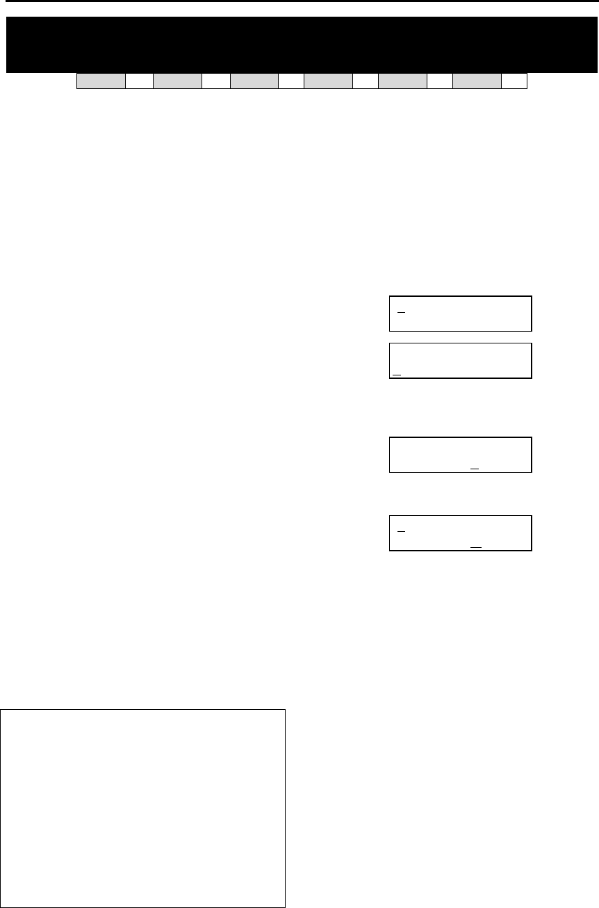
DCS MMC PROGRAMS
COMBINED PROGRAMMING MANUAL NOVEMBER 2001
MMC 311 [DCS] (Page 1 of 2)
MMC: 311 ASSIGN SIM PARAMETER
DCS ✓
✓✓
✓ CI ✗
✗✗
✗ CII ✗
✗✗
✗ 816 ✗
✗✗
✗ 408i ✗
✗✗
✗ 408 ✗
✗✗
✗
Assigns and sets parameters for the serial interface module (SIM). Refer to tables 1–12, below.
PROGRAM KEYS
UP & DOWN Used to scroll through options
KEYPAD Used to enter selections
SOFT KEYS Move cursor left and right
SPEAKER Used to store data and advance to next MMC
HOLD Used to clear previous entry
ACTION DISPLAY
1. Open programming and select 311
Display shows
[256] SIM PARA
SIM TYPE :DTE
2. Enter station number connected to SIM (e.g., 257)
from dial keypad
OR
Press UP or DOWN key to make selection and press
RIGHT soft key to move cursor
[257] SIM PARA.
SIM TYPE :DTE
3. Enter desired selection from table 1 (00–10, e.g. 01)
OR
Press UP or DOWN key to make selection and press
RIGHT soft key to move cursor
[257] SIM PARA.
CALL MODE:AWITH
Refer to table 1 for your selected option and go to
the table indicated (e.g. 3) to enter required
value (e.g. 0) using dial keypad or by pressing UP or
DOWN key
Press RIGHT soft key to move cursor
[257] SIM PARA.
CALL MODE:MANUAL
4. Repeat step 3 for all required options (00–10 in table 1)
5. Press TRSF to store and exit
OR
Press SPEAKER to store and advance to next MMC
TABLE 1. SIM PARAMETER
00 SIM TYPE = Table 2
01 CALL MODE = Table 3
02 ANS MODE = Table 4
03 AUTO BAUD = Table 5
04 DTR CHECK = Table 6
05 ECHO = Table 7
06 PROTOCOL = Table 8
07 SPEED = Table 9
08 CHAR LENGTH = Table 10
09 PARITY = Table 11
10 STOP BIT = Table 12

DCS MMC PROGRAMS
COMBINED PROGRAMMING MANUAL NOVEMBER 2001
MMC 311 [DCS] (Page 2 of 2)
TABLE 2. SIM TYPE
0 HOST
1 MODEM
2 DTE
3 PRT
TABLE 8. PROTOCOL
0 V110
1 V120
TABLE 3. CALL MODE
0 MANUAL
1 AUTO WITH
2 AUTO WITHOUT
TABLE 4. ANS MODE
0 MANUAL
1 AUTO
TABLE 9. SPEED TABLE
0 300
1 600
2 1200
3 2400
4 4800
5 9600
6 19200
7 38400
8 48000
9 56000
TABLE 5. AUTO BAUD
0 OFF
1 ON
TABLE 10. CHAR LENGTH
0 8
1 7
2 6
3 5
TABLE 6. DTR CHECK
0 OFF
1 ON
TABLE 11. PARITY TABLE
0 NONE
1 ODD
2 EVEN
TABLE 7. ECHO
0 OFF
1 ON
TABLE 12. STOP BIT
0 1
1 1.5
2 2
Default Data: SIM Type = DTE
Call Mode = Manual
Ans Mode = Manual
Auto Baud = ON
DTR Check = ON
Echo = ON
Protocol = V110
Speed = 9600
Char Length = 8 Bits
Parity = None
Stop Bit = 1
Related Items: MMC 804 System I/O Parameter
DCS MMC PROGRAMS
COMBINED PROGRAMMING MANUAL NOVEMBER 2001
MMC 312 (Page 1 of 2)
MMC: 312 ALLOW CLIP
DCS 33 CI 33 CII 33 816 33 408i 33 408 77
Allows the system installer or administrator to:
§ allow or prevent receipt of CLIP data from the network
§ request or restrict sending of CLIP data to the network.
Each station can have the following options:
SND: YES - request the network to send Caller ID when outgoing call is made.
NO - request the network NOT to send Caller ID when outgoing call is made.
RCV: YES - allow display of CLIP data at keysets.
NO - prevent display of CLIP data at keysets.
INFO: If YES selected for SND option, you can select the CLIP display option from
0 CO Tel
1 Extn. Number
2 CO + Extn. No.
3 DID Number.
ACTION DISPLAY
1. Open programming and select 312
Display shows
[201] ALLOW CLIP
RCV:YES SND:YES
2. Dial station number (e.g., 205)
OR
Press UP or DOWN to select station and press right
soft key to move cursor
OR
Press ANS/RLS to select all
[205] ALLOW CLIP
RCV:YES SND:YES
OR
[ALL] ALLOW CLIP
RCV:YES SND:YES
3. Dial 0 (NO) or 1 (YES) to select RCV option (e.g. 1)
OR
Press UP or DOWN to select option and press right
soft key to move cursor to SND field
[205] ALLOW CLIP
RCV:YES SND:YES
4. Dial 0 (NO) or 1 (YES) to select SND option (e.g. 1)
OR
Press UP or DOWN to select option and press right
soft key
[205] ALLOW CLIP
RCV:YES SND:YES
If you selected YES for SND option, display shows
Dial 0–3 to select INFO option
OR
Press UP or DOWN to select
Press RIGHT soft key
[205] ALLOW CLIP
INFO:C.O Tel.

DCS MMC PROGRAMS
COMBINED PROGRAMMING MANUAL NOVEMBER 2001
MMC 312 (Page 2 of 2)
4. Press TRSF to store and exit
OR
Press SPEAKER to save and advance to next MMC
Default Data : RCV=YES
SND=YES
INFO=CO Tel
Related Items: MMC 119 Set CLIP Display
DCS MMC PROGRAMS
COMBINED PROGRAMMING MANUAL NOVEMBER 2001
MMC 313 [Compact I] (Page 1 of 1)
MMC: 313 ASSIGN PIN CODE
DCS 77 CI 33 CII 77 816 77 408i 77 408 77
Assigns individual users to PIN codes in the system. For Cable & Wireless 131 service there is a
maximum of four PIN codes allocated in the system, so users must be assigned to the PIN code
used when dialling out on a Cable & Wireless Network.
This MMC is related only to 131 Cable & Wireless service.
ACTION DISPLAY
1. Open programming and select 313
Display shows [201] PIN CODE
PIN CODE # : NONE
2. Dial the station number (e.g., 205)
OR
Press UP or DOWN key to select station
and press RIGHT soft key to advance to step 3
[205] PIN CODE
PIN CODE # : NONE
3. Enter the pin code serial number (1, 2, 3 or 4, e.g. 1) [205] PIN CODE
PIN CODE # : 1
4. Press TRSF to store and exit
OR
Press SPEAKER to store and advance to next
MMC
Default Data: All stations are code #1
Related Items: MMC 217 CCC Option
MMC 716 UK LCR Option
MMC 717 Pin Code
DCS MMC PROGRAMS
COMBINED PROGRAMMING MANUAL NOVEMBER 2001
MMC 314 (Page 1 of 1)
MMC: 314 CONFIRM OUTGOING CALL
DCS 33 CI 77 CII 33 816 33 408i 33 408 33
Allows outgoing call restriction, disconnect or confirm with tone.
PROGRAM KEYS
UP & DOWN Used to scroll through options
KEYPAD Used to enter selections
SOFT KEYS Move cursor left and right
SPEAKER Used to store data and advance to next MMC
HOLD Used to clear previous entry
ANS/RLS Used to select ALL
FEATURE KEYS
0 NONE
1 CONFIRM TONE
2 DISCONNECT
ACTION DISPLAY
1. Open programming and select 314
Display shows [201] CO CONFIRM
NONE
2. Dial station number (e.g., 205)
OR
Press UP or DOWN key to select station and press
RIGHT soft key to move cursor
[205] CO CONFIRM
NONE
3. Dial a feature option 0-2 (e.g., 1)
OR
Press UP or DOWN key to select option
and press RIGHT soft key to return to step 2
[205] CO CONFIRM
CONFIRM TONE
4. Press TRSF to store and exit
OR
Press SPEAKER to store and advance to next MMC
Default Data: NONE
Related Items: MMC 501 System-Wide Timers
DCS MMC PROGRAMS
COMBINED PROGRAMMING MANUAL NOVEMBER 2001
MMC 315 (Page 1 of 1)
MMC: 315 SET RELOCATION
DCS 33 CI 77 CII 33 816 33 408i 33 408 33
Used when a station moves its phone to another location (a different port). All relevant data for
the phone are moved to the new location automatically.
ACTION DISPLAY
1. Open programming and select 315
Display shows
SET RELOCATION
EXT EXT
2. Dial the original station number (e.g. 205)
OR
Press UP or DOWN key to select station and press
RIGHT soft key
SET RELOCATION
EXT205 EXT_
3. Dial the new location's station number (e.g. 210)
SET RELOCATION
EXT205 EXT210
4. Press TRSF to store and exit
OR
Press SPEAKER to store and advance to next MMC
Default Data: None
Related Items: None
DCS MMC PROGRAMS
COMBINED PROGRAMMING MANUAL NOVEMBER 2001
MMC 316 (Page 1 of 1)
MMC: 316 COPY STATION USABLE
DCS 33 CI 77 CII 33 816 33 408i 77 408 77
Copy the condition of station/trunk usability and station/station usability from one station to an-
other station.
PROGRAM KEYS
UP & DOWN Used to scroll through options
KEYPAD Used to enter selections
SOFT KEYS Move cursor left and right
SPEAKER Used to store data and advance to next MMC
HOLD Used to clear previous entry
ACTION DISPLAY
1. Open programming and select 316
Display shows
[201] CPY USABLE
FROM:NONE
2. Enter destination station number (e.g. 205)
OR
Press UP or DOWN key to make selection and press
RIGHT soft key to move cursor
[205] CPY USABLE
FROM:NONE
3. Enter the source station number (e.g. 210)
OR
Press UP or DOWN key to make selection and press
RIGHT soft key to move cursor
[205] CPY USABLE
FROM:210
4. Press TRSF to store and exit
OR
Press SPEAKER to store and advance to next MMC
Default Data: NONE
Related Items: MMC 304 Assign Station/Trunk Use
MMC 317 Assign Station/Station Use
DCS MMC PROGRAMS
COMBINED PROGRAMMING MANUAL NOVEMBER 2001
MMC 317 (Page 1 of 1)
MMC: 317
ASSIGN STATION / STATION USE
DCS 33 CI 77 CII 33 816 33 408i 77 408 77
Used to control whether a station can dial other stations.
PROGRAM KEYS
UP & DOWN Used to scroll through options
KEYPAD Used to enter selections
SOFT KEYS Move cursor left and right
SPEAKER Used to store data and advance to next MMC
HOLD Used to clear previous entry
ANS/RLS Used to select ALL
ACTION DISPLAY
(In the following example, you do not want station 205 to be able to dial station 204.)
1. Open programming and select 317
Display shows
[201] USE [201]
DIAL:YES
2. Dial the first station number (e.g., 205)
OR
Press UP or DOWN key to select station and press
RIGHT soft key
OR
Press ANS/RLS to select all stations
[205] USE [201]
DIAL:YES
3. Dial the second station number (e.g., 204)
OR
Press UP or DOWN key to select station and press
RIGHT soft key
[205] USE [204]
DIAL:YES
4. Dial 1 for YES or 0 for NO
OR
Press UP or DOWN key to select YES/NO and press
RIGHT soft key to move cursor
[205] USE [204]
DIAL:NO
5. Press TRSF to store and exit
OR
Press SPEAKER to store and advance to next MMC
Default Data: DIAL=YES
Related Items: MMC 316 Copy Station Usable
DCS MMC PROGRAMS
COMBINED PROGRAMMING MANUAL NOVEMBER 2001
MMC 318 (Page 1 of 1)
MMC: 318 DISTINCTIVE RING
DCS 33 CI 77 CII 33 816 33 408i 33 408 33
Sets a distinctive ring for stations. You can set both tone (T) and cadence (C) to one of eight ring
values (1-8), or to follow the station ring (F-STN).
PROGRAM KEYS
UP & DOWN Used to scroll through options
KEYPAD Used to enter selections
SOFT KEYS Move cursor left and right
SPEAKER Used to store data and advance to next MMC
ACTION DISPLAY
1. Open programming and select 318
Display shows
[201] DIST.RING
T:F-STN C:F-STN
2. Dial station number (e.g., 205)
OR
Press UP or DOWN to select station and press RIGHT
soft key to move cursor
[205] DIST.RING
T:F-STN C:F-STN
3. Press UP or DOWN to select T value (e.g. 1) and press
RIGHT soft key to move cursor to C field
[205] DIST.RING
T:1 C:F-STN
4. Press UP or DOWN to select C value
(e.g. 2)
[205] DIST.RING
T:1 C:2
5. Press TRSF to store and exit
OR
Press SPEAKER to save and advance to next MMC
Default Data : T: F-STN
C: F-STN
Related Items: None

DCS MMC PROGRAMS
COMBINED PROGRAMMING MANUAL NOVEMBER 2001
MMC 319 (Page 1 of 1)
MMC: 319
BRANCH GROUP
Not Used in the UK
DCS MMC PROGRAMS
COMBINED PROGRAMMING MANUAL NOVEMBER 2001
MMC 400 (Page 1 of 1)
MMC: 400 CUSTOMER ON/OFF
PER TRUNK
DCS 33 CI 33 CII 33 816 33 408i 33 408 33
Assigns several options (listed below) on a per-trunk basis.
OPTIONS
0 1A2 EMULATE Trunk override call (NO PRIVACY)
1 TRUNK INC DND Allows trunk to override DND (DIL)
2 TRUNK FORWARD Allows trunk to be forwarded
3 LCR ALLOW Allows LCR to be switched ON/OFF when a
trunk is directly accessed.
Note: ‘1A2 Emulation’ means that a third party can be joined on an existing trunk conversation by pressing
the DTS key for the line on their keyset.
PROGRAM KEYS
UP & DOWN Used to scroll through options
KEYPAD Used to enter selections
SOFT KEYS Move cursor left and right
SPEAKER Used to store data and advance to next MMC
HOLD Used to clear previous entry
ANS/RLS Used to select ALL
ACTION DISPLAY
1. Open programming and select 400
Display show [701] TRK ON/OFF
1A2 EMULATE:OFF
2. Dial trunk number (e.g. 704)
OR
Press UP or DOWN key to select trunk
OR
Press ANS/RLS for all trunks and press RIGHT soft key
to move cursor to options
[704] TRK ON/OFF
1A2 EMULATE:OFF
OR
[ALL] TRK ON/OFF
1A2 EMULATE :?
3. Dial option number from above list (0–3, e.g. 2)
OR
Press UP or DOWN key to select option and press
RIGHT soft key to move cursor
[704] TRK ON/OFF
TRK FORWARD :ON
4. Dial 1 for ON or 0 for OFF
OR
Press UP or DOWN key to select ON/OFF and press
RIGHT soft key to return to step 2
[704] TRK ON/OFF
TRK FORWARD: OFF
5. Press TRSF to store and exit
OR
Press SPEAKER to store and advance to next MMC
Default Data: 1A2 EMULATE Off
TRUNK INC DND Off
TRUNK FORWARD On
LCR ALLOW Off
Related Items: None
DCS MMC PROGRAMS
COMBINED PROGRAMMING MANUAL NOVEMBER 2001
MMC 401 (Page 1 of 1)
MMC: 401 C.O. / PBX LINE
DCS 33 CI 33 CII 33 816 33 408i 33 408 33
Used to select the mode of the C.O. line. If PBX mode is chosen, this allows PBX access codes
to be recognised, thus allowing more complete toll restriction (call barring). This mode is as-
signed on a per-trunk basis. If a trunk requires the use of the RECALL key, it must be set to PBX
mode. Options are:
0 CO LINE
1 PBX
PROGRAM KEYS
UP & DOWN Used to scroll through options
KEYPAD Used to enter selections
SOFT KEYS Move cursor left and right
SPEAKER Used to store data and advance to next MMC
HOLD Used to clear previous entry
ANS/RLS Used to select ALL
ACTION DISPLAY
1. Open programming and select 401
Display shows
[701] PBX LINE
CO LINE
2. Dial trunk number (e.g., 704)
OR
Use UP or DOWN to scroll through trunk numbers and
press RIGHT soft key to move cursor
OR
Press ANS/RLS to select ALL
[704] PBX LINE
CO LINE
OR
[ALL] PBX LINE
?
3. Dial 1 for PBX or 0 for C.O.
OR
Use UP or DOWN to scroll through options
Press RIGHT soft key to return to step 2
[704] PBX LINE
PBX LINE
4. Press TRSF to store and exit
OR
Press SPEAKER to store and advance to next MMC
Default Data: All trunks C.O. Line
Related Items: None
DCS MMC PROGRAMS
COMBINED PROGRAMMING MANUAL NOVEMBER 2001
MMC 402 (Page 1 of 1)
MMC: 402 TRUNK DIAL TYPE
DCS 33 CI 33 CII 33 816 33 408i 77 408 33
Used to determine the dialling type of each C.O. line. There are two options:
0 Dual tone multi frequency (DTMF)
1 Pulse (rotary dial)
PROGRAM KEYS
UP & DOWN Used to scroll through options
KEYPAD Used to enter selections
SOFT KEYS Move cursor left and right
SPEAKER Used to store data and advance to next MMC
HOLD Used to clear previous entry
ANS/RLS Used to select ALL
ACTION DISPLAY
1. Open programming and select 402
Display shows
[701] DIAL TYPE
DTMF TYPE
2. Dial trunk number (e.g., 704)
OR
Use UP or DOWN to scroll through trunk numbers and
press RIGHT soft key to move the cursor
OR
Press ANS/RLS to select ALL
[704] DIAL TYPE
DTMF TYPE
OR
[ALL] DIAL TYPE
?
3. Dial 1 for PULSE or 0 for DTMF (e.g. 1)
OR
Use UP or DOWN to scroll through options
Press RIGHT soft keys to return to step 2
[704] DIAL TYPE
DIAL PULSE TYPE
4. Press TRSF to store and exit
OR
Press SPEAKER to store and advance to next MMC
Default Data: All trunks DTMF
Related Items: MMC 501 System-Wide Timers
MMC 503 Trunk-Wide Timers

DCS MMC PROGRAMS
COMBINED PROGRAMMING MANUAL NOVEMBER 2001
MMC 403 (Page 1 of 2)
MMC: 403 TRUNK TOLL CLASS
DCS 33 CI 33 CII 33 816 33 408i 33 408 33
Assigns toll class level assignments on a per-trunk or all-trunk basis in a day or night condition.
The options for toll level will follow either the station class or the class of service defined in MMCs
702, Toll Deny Table, and 703, Toll Allowance Table. The toll classes available are listed below:
ENTRY NUMBER CLASS TYPE DESCRIPTION
0 F-STN Follow station toll restriction
1 CLS-A Follow toll class A (Unrestricted)
2 CLS-B Follow toll class B
3 CLS-C Follow toll class C
4 CLS-D Follow toll class D
5 CLS-E Follow toll class E
6 CLS-F Follow toll class F
7 CLS-G Follow toll class G
8 CLS-H Follow toll class H (All restricted)
PROGRAM KEYS
UP & DOWN Used to scroll through options
KEYPAD Used to enter selections
SOFT KEYS Move cursor left and right
SPEAKER Used to store data and advance to next MMC
HOLD Used to clear previous entry
ANS/RLS Used to select ALL
ACTION DISPLAY
1. Open programming and select 403
Display shows
[701] TOLL CLASS
D:F-STN N:F-STN
2. Dial trunk number (e.g.704)
OR
Use UP or DOWN to scroll through trunk numbers and
press RIGHT soft key to move the cursor
OR
Press ANS/RLS to select ALL
[704] TOLL CLASS
D:F-STN N:F-STN
OR
[ALL] TOLL CLASS
D:F-STN N:F-STN
3. Enter day toll class (e.g. 2 for CLS-B)
OR
Press UP or DOWN to scroll through toll classes
and use RIGHT soft key to move the cursor
[704] TOLL CLASS
D:CLS-B N:F-STN
4. Enter night toll class (e.g., 2)
OR
Press UP or DOWN to scroll through toll classes
and use RIGHT soft key to return to step 2
[704] TOLL CLASS
D:CLS-B N:CLS-B
5. Press TRSF to store data and exit
OR
Press SPEAKER to store data and advance to next MMC

DCS MMC PROGRAMS
COMBINED PROGRAMMING MANUAL NOVEMBER 2001
MMC 403 (Page 2 of 2)
Default Data: All trunks F-STN day/night
Related Items: MMC 301 Assign Station COS
MMC 507 Assign Auto Night Time
MMC 701 Assign COS Contents
Toll Restriction
DCS MMC PROGRAMS
COMBINED PROGRAMMING MANUAL NOVEMBER 2001
MMC 404 (Page 1 of 1)
MMC: 404 TRUNK NAME
DCS 33 CI 33 CII 33 816 33 408i 33 408 33
Allows a name, up to 11 characters, to be entered to identify an individual trunk.
Names are written using the keypad. Each key press selects a character and moves the cursor to
the next position. For example, if the name is “TELECOMS”, press the number “8” once to get
the letter “T”. Now press the number “3” twice to get the letter “E.” Continue selecting characters
from the keypad to complete the name. Press the programmable “A” key to toggle between up-
per and lower case text.
Tip: When the character you want is on the same key as the previous character you typed in, press the UP
key to move the cursor to the right, then select the character.
The # key can be used for the following special characters (in sequence of key presses):
#
space
& ! : ? . , % $ - < > / =
[ ] @ ^ ( ) _ + { } | ; " → `
PROGRAM KEYS
UP & DOWN Used to scroll through options/move cursor left or right
KEYPAD Used to enter selections
SOFT KEYS Move cursor left and right
SPEAKER Used to store data and advance to next MMC
HOLD Used to clear previous entry
“A” Key #19 (24B keyset) or key #7 (12B keyset) or key #1 (6B keyset)
toggles upper case and lower case text.
ACTION DISPLAY
1. Open programming and select 404
Display shows
[701] TRUNK NAME
2. Dial trunk (e.g., 704)
OR
Press UP or DOWN to select trunk and press the
RIGHT soft key to move the cursor
[704] TRUNK NAME
_
3. Enter trunk name using the procedure described
above
Press RIGHT soft key to return to step 2
[704] TRUNK NAME
TELECOMS
4. Press TRSF to store and exit
OR
Press SPEAKER to store and advance to next MMC
Default Data: No names entered
Related Items: MMC 104 Station Name
MMC 405 Trunk Number
DCS MMC PROGRAMS
COMBINED PROGRAMMING MANUAL NOVEMBER 2001
MMC 405 (Page 1 of 1)
MMC: 405 TRUNK NUMBER
DCS 33 CI 33 CII 33 816 33 408i 33 408 33
Allows a number, up to 11 digits, to be entered to identify an individual trunk.
Numbers are entered using the keypad. Pressing a key selects a digit and moves the cursor to
the next position.
The # key can be used for the following special characters (in sequence of key presses):
#
space
& ! : ? . , % $ - < > / =
[ ] @ ^ ( ) _ + { } | ; " → `
PROGRAM KEYS
UP & DOWN Used to scroll through options/move cursor left or right
KEYPAD Used to enter selections
SOFT KEYS Move cursor left and right
SPEAKER Used to store data and advance to next MMC
HOLD Used to clear previous entry
“A” Key #19 (24B keyset) or key #7 (12B keyset) or key #1 (6B keyset)
toggles upper case and lower case
ACTION DISPLAY
1. Open programming and select 405
Display shows
[701] CO TEL NO.
2. Dial trunk (e.g., 704)
OR
Press UP or DOWN to select trunk and press RIGHT
soft key to move the cursor
[704] CO TEL NO.
_
3. Enter the trunk number
[704] CO TEL NO.
3054264100
4. Press RIGHT soft key to return to step 2
OR
Press TRSF to store and exit
OR
Press SPEAKER to store and advance to next MMC
Default Data: No numbers entered
Related Items: MMC 404 Trunk Name
DCS MMC PROGRAMS
COMBINED PROGRAMMING MANUAL NOVEMBER 2001
MMC 406 (Page 1 of 1)
MMC: 406 TRUNK RING ASSIGNMENT
DCS 33 CI 33 CII 33 816 33 408i 33 408 33
Enables ringing to a specific station or a group of stations (or an auto attendant for systems other
than 408/408i) when incoming calls are received. This MMC controls both day and night loca-
tions.
DEVICE DEFAULT DIRECTORY NO.
DCS Compact II 816 408/408i
Station 201–349 201–308 201–216 21–28
Station group 500-529 500-519 500–509 50–53
AA 39xx 38x 38x –
PROGRAM KEYS
UP & DOWN Used to scroll through options
KEYPAD Used to enter selections
SOFT KEYS Move cursor left and right
SPEAKER Used to store data and advance to next MMC
HOLD Used to clear previous entry
ANS/RLS Used to select ALL (trunks only)
ACTION DISPLAY
1. Open programming and select 406
Display shows
[701] TRK RING
D:500 N:500
2. Dial trunk number (e.g., 704)
OR
Use UP or DOWN to scroll through trunk numbers and
press the RIGHT soft key to move the cursor
[704] TRK RING
D:500 N:500
3. Dial station number or station group number for day
(e.g., 205)
OR
Press UP or DOWN key to select station number or sta-
tion group number and press RIGHT soft key to
move cursor
[704] TRK RING
D:205 N:500
4. Dial station number or station group number for night
(e.g., 501)
OR
Press UP or DOWN key to select station number or sta-
tion group number and press RIGHT soft key to
move cursor
[704] TRK RING
D:205 N:501
5. Press TRSF to store and exit
OR
Press SPEAKER to store and advance to next MMC
Default Data: All trunks day: 500, night: 500 (day and night=50 for 408/408i systems)
Related Items: MMC 202 Change Feature Passcodes
MMC 507 Assign Auto Night Time
MMC 601 Assign Station Group

DCS MMC PROGRAMS
COMBINED PROGRAMMING MANUAL NOVEMBER 2001
MMC 407 (Page 1 of 1)
MMC: 407 FORCED TRUNK RELEASE
DCS 33 CI 33 CII 33 816 33 408i 33 408 33
Provides a positive forced trunk release to a specific trunk or all trunks in the event of a trunk
lock-up.
PROGRAM KEYS
UP & DOWN Used to scroll through options
KEYPAD Used to enter selections
SOFT KEYS Move cursor left and right
SPEAKER Used to store data and advance to next MMC
HOLD Used to clear previous entry
ANS/RLS Used to select ALL
ACTION DISPLAY
1. Open programming and select 407
Display shows [701] TRK RELS.
RELEASE? Y:1,N:0
2. Dial in trunk number ( e.g., 704)
OR
Press UP or DOWN key selected trunk and press right
soft key
OR
Press ANS/RLS to select all trunks
[704] TRK RELS.
RELEASE?_Y:1,N:0
[ALL] TRK RELS.
RELEASE?_Y:1,N:0
3. Dial 1 for YES or 0 for NO (e.g. 1)
System returns to step 2
[704] TRK RELS.
RELEASE? Y:1,N:0
4. Press TRSF to store and exit
OR
Press SPEAKER to store and advance to next MMC
Default Data: None
Related Items: MMC 603 Assign Trunk Group
DCS MMC PROGRAMS
COMBINED PROGRAMMING MANUAL NOVEMBER 2001
MMC 408 (Page 1 of 1)
MMC: 408 ASSIGN TRUNK MUSIC ON
HOLD SOURCE
DCS 33 CI 33 CII 33 816 33 408i 33 408 33
Allows the system administrator to select which Music On Hold (MOH) source can be heard on
each trunk. The possible selections for each music source are: TONE, NONE, internal and exter-
nal (customer-provided MOH source).
DCS
Connected to a Trunk A card. The default directory number of an MOH source is 37xx.
Compact II
There is a total of two possible music sources, but this depends on whether a Misc card is in-
stalled in the system. One music source is provided on the base board (switch select inter-
nal/external); the other external source is provided on the Misc card. The default directory num-
ber of a background music source is 371–372.
816 and 408/408i
There is a music source on the base board (switch select internal/external). The default directory
number of a background music source is 371.
Note: Internal music is always the odd numbered address, e.g. 371, 3701, 3703.
PROGRAM KEYS
UP & DOWN Used to scroll through options
KEYPAD Used to enter selections
SOFT KEYS Move cursor left and right
SPEAKER Used to store data and advance to next MMC
HOLD Used to clear previous entry
ANS/RLS Used to select ALL
ACTION DISPLAY
1. Open programming and select 408
Display shows current setting
[701] TRK MOH
MOH SOURCE:TONE
2. Dial trunk number (e.g., 704)
OR
Use UP or DOWN to scroll through trunk
numbers and press RIGHT soft key to move cursor
OR
Press ANS/RLS to select ALL
[704] TRK MOH
MOH SOURCE:TONE
OR
[ALL] TRK MOH
MOH SOURCE:?
3. Enter source number (e.g., 3701)
OR
Press UP or DOWN key to select option
Press RIGHT soft key to return to step 2 above
[704] TRK MOH
MOH SOURCE:3701
4. Press TRSF to store and exit
OR
Press SPEAKER to store and advance to next MMC
Default Data: TONE
Related Items: MMC 308 Assign Background Music Source
DCS MMC PROGRAMS
COMBINED PROGRAMMING MANUAL NOVEMBER 2001
MMC 409 (Page 1 of 2)
MMC: 409 TRUNK STATUS READ
DCS 33 CI 33 CII 33 816 33 408i 33 408 33
This is a read-only MMC. Allows the status of trunks to be read in a format that will enable the
servicing personnel to quickly identify the ownership and position of a trunk.
OPTIONS
Dial DCS COMPACT II & 816 & 408/408i
00 Port Number Port Number
01 Tenant Number Type: e.g. LOOP, DDI, BRI, PRI …
02 Type: e.g. LOOP, DDI, BRI, PRI … 1A2 Emulation Status (On/Off)
03 1A2 Emulation Status (On/Off) Trunk Forward Status (On/Off)
04 Trunk Forward Status (On/Off) Line Type (CO/PBX)
05 Line Type (CO/PBX) Dial Type (DTMF/Dial Pulse)
06 Dial Type (DTMF/Dial Pulse) Day Toll Restriction
07 Day Toll Restriction Night Toll Restriction
08 Night Toll Restriction Day Ring Destination
09 Day Ring Destination Night Ring Destination
10 Night Ring Destination MOH Source
11 MOH Source DISA Status
12 DISA Status –
PROGRAM KEYS
UP & DOWN Used to scroll through options
KEYPAD Used to enter selections
SOFT KEYS Move cursor left and right
SPEAKER Used to store data and advance to next MMC
HOLD Used to clear previous entry
ACTION DISPLAY
1. Open programming and select 409
Display shows (e.g. for Compact II) [701] TRK STATUS
PORT NO::EX1-01
2. Enter trunk number via dial keypad (e.g., 704)
OR
Press UP or DOWN key to make selection and press
RIGHT soft key to advance cursor
[704] TRK STATUS
PORT NO::EX1-04
3. Enter desired option 00-12 from table above
OR
Press UP or DOWN key to make selection
[704] TRK STATUS
1A2 EMULATE:OFF
4. Press TRSF to store and exit
OR
Press SPEAKER to store and advance to next MMC

DCS MMC PROGRAMS
COMBINED PROGRAMMING MANUAL NOVEMBER 2001
MMC 409 (Page 2 of 2)
Default Data: Port Number=Trunk port number
Tenant No.=1
Type=Loop
1A2 Emulation=OFF
Trk Fwd=ON
Line Type=CO
Dial Type=DTMF
Day Toll=F–STN
Night Toll=F–STN
Day Ring Dest=500 (50 for 408/408i)
Night Ring Dest=500 (50 for 408/408i)
MOH Source=Tone
DISA Status=Normal
Related Items: MMC 400 Customer On/Off Per Trunk
MMC 401 C.O./PBX Line
MMC 402 Trunk Dial Type
MMC 403 Trunk Toll Class
MMC 404 Trunk Name
MMC 406 Trunk Ring Assignment
MMC 408 Assign Trunk Music On Hold Source
MMC 410 Assign DISA Trunk
DCS MMC PROGRAMS
COMBINED PROGRAMMING MANUAL NOVEMBER 2001
MMC 410 (Page 1 of 1)
MMC: 410 ASSIGN DISA TRUNK
DCS 33 CI 33 CII 33 816 33 408i 33 408 33
Allows the system to have Direct Inward System Access (DISA). Because there is a possibility
that unauthorised calls will be made via this feature, several safeguards have been added. The
user must be informed of these to prevent unnecessary service calls. DISA can lock out when a
predetermined number of invalid consecutive calls are attempted. Callers will then receive ring
back tone until a programmable timer has expired. The [ key may be used to initiate new dial
tone while in a station-to-station call. The # key may be used to terminate the DISA call and dis-
connect the central office line. Multiple central office calls and internal calls are possible.
Note: In order to use DISA, the caller must first dial a valid station number, followed by a four-digit pass-
code. This passcode is defined in MMC 101, Change User Passcode. DISA users MUST change this pass-
code as the default number cannot be used.
PROGRAM KEYS
UP & DOWN Used to scroll through options
KEYPAD Used to enter selections
SOFT KEYS Move cursor left and right
SPEAKER Used to store data and advance to next MMC
HOLD Used to clear previous entry
ANS/RLS Used to select ALL (trunks)
FEATURE KEYS
0 NORMAL No DISA service
1 DAY DISA is available in day mode
2 NIGHT DISA is available in night mode
3 BOTH DISA is available in both day and night mode
ACTION DISPLAY
1. Open programming and select 410
Display shows [701] DISA LINE
NORMAL
2. Dial trunk number ( e.g., 704)
OR
Press UP or DOWN key to select trunk and press
RIGHT soft key
OR
Press ANS/RLS key to select all trunks
[704] DISA LINE
NORMAL
OR
[ALL] DISA LINE
?
3. Dial an option (0–3) from above table
OR
Press UP or DOWN key to select trunk and
press RIGHT soft key to return to step 2
[704] DISA LINE
NIGHT
4. Press TRSF to store and exit
OR
Press SPEAKER to store and advance to next MMC
Default Data: All trunks normal
Related Items: MMC 101 Change User Passcode
MMC 500 System-Wide Counters
MMC 210 Customer On/Off (DISA PSWD option)

DCS MMC PROGRAMS
COMBINED PROGRAMMING MANUAL NOVEMBER 2001
MMC 411 (Page 1 of 1)
MMC: 411 ASSIGN E1 SIGNAL TYPE
Not Used in UK
DCS MMC PROGRAMS
COMBINED PROGRAMMING MANUAL NOVEMBER 2001
MMC 412 [DCS / Compact II] (Page 1 of 1)
MMC: 412 ASSIGN TRUNK SIGNAL
DCS 33 CI 33 CII 33 816 77 408i 77 408 77
Allows for the assignment of AC15 cards for proper signalling. This MMC is only for analogue
types of AC15 trunks. These trunks can also use the translation tables in MMC 714, DDI Number
and Name Translation. The AC15 trunks are allowed the use of translation tables via MMC 416,
Assign AC15 Translation. The signalling condition types are as follows:
0 IMMEDIATE START
1 DELAYED START
2 WINK START
3 NO ANSWER BACK
4 DIRECT BACK
PROGRAM KEYS
UP & DOWN Used to scroll through options
KEYPAD Used to enter selections
SOFT KEYS Move cursor left and right
SPEAKER Used to store data and advance to next MMC
ANS/RLS Used to select ALL
ACTION DISPLAY
1.
Open programming and select 412
Display shows
[701] TRK SIGNAL
IMMEDIATE START
2.
Enter desired trunk number (e.g., 705)
OR
Press UP or DOWN key to make selection and press
RIGHT soft key to move cursor
OR
Press ANS/RLS to select all trunks
[705] TRK SIGNAL
IMMEDIATE START
3. Enter desired trunk type selection from above list
OR
Press UP or DOWN key to make selection and press
RIGHT soft key
[705] TRK SIGNAL
WINK START
4. Press TRSF to store and exit
OR
Press SPEAKER to store and advance to next MMC
Default Data: All AC15 trunks set to IMMEDIATE START
Related Items: MMC 714 DDI Number and Name Translation
DCS MMC PROGRAMS
COMBINED PROGRAMMING MANUAL NOVEMBER 2001
MMC 414 (Page 1 of 1)
MMC: 414 MPD/PRS SIGNAL
DCS 33 CI 33 CII 33 816 33 408i 77 408 33
Used on a per-trunk basis to define if a C.O. line is to be either a Metering Pulse (MPD) or a Po-
larity Reversal Signal (PRS) trunk. (Note: PRS is not available in the UK.)
A Meter Pulse Trunk will detect a C.O.-provided meter pulse. A Polarity Reversal trunk will detect
the line reversal signal which may be provided by the C.O. when the other party answers the out-
going call or the outside party clears the call. If the trunk is designated as PRS detection, the call
duration timer will be started and the results printed on the SMDR record. PRS detection is also
essential for dropping a trunk-to-trunk conversation which is unsupervised by an internal party.
ACTION DISPLAY
1.
Open programming and select 414
Display shows
[701] TRK PRS
NONE
2.
Enter desired trunk number (e.g. 705)
OR
Press UP or DOWN key to select trunk and use
LEFT or RIGHT soft key to move cursor
[705] TRK PRS
NONE
3. Press UP or DOWN key to scroll through options
and use LEFT or RIGHT soft key to return to step 2
[705] TRK PRS
MPD
4. Press TRSF to store and exit
OR
Press SPEAKER to store and advance to next MMC
Default Data: NONE
Related Items: MMC 508 Call Cost
DCS MMC PROGRAMS
COMBINED PROGRAMMING MANUAL NOVEMBER 2001
MMC 415 (Page 1 of 1)
MMC: 415 REPORT TRUNK
ABANDON DATA
DCS 33 CI 33 CII 33 816 33 408i 33 408 77
Allows the system administrator or technician to enable or disable the reporting of abandoned
C.O. calls for which CLIP information has been collected on a per-trunk basis.
There are two options for this MMC:
0 REPORT : NO Abandoned call records for incoming calls with CLIP information will not be
printed on SMDR or stored in the system abandoned call list.
These records will continue to be stored in the station review list.
1 REPORT : YES Abandoned call records for incoming calls with CLIP information will be
printed on SMDR or stored in the system abandoned call list.
These records will also be stored in the station review list.
Note: In order for these abandoned call records to print on SMDR, use MMC 725 (SMDR Options) and set
Option 11 - Abandon Call - to YES.
ACTION DISPLAY
1. Open programming and select 415
Display shows
[701] TRK ABNDN
REPORT : YES
2. Dial trunk number (e.g. 705)
OR
Press UP or DOWN to select trunk and use LEFT or
RIGHT soft key to move cursor
[705] TRK ABNDN
REPORT : YES
3. Dial 1 for YES or 0 for NO (e.g. 0)
OR
Press UP or DOWN to scroll through options and use
LEFT or RIGHT soft key to return to step 2
[705] TRK ABNDN
REPORT : NO
4. Press TRSF to store and exit
OR
Press SPEAKER to store and advance to next MMC
Default Data : REPORT: YES
Related Items: MMC 119 Set CLIP Display
MMC 312 Allow CLIP
MMC 608 Assign CLIP Review Block
MMC 722 Station Key Programming
MMC 723 System Key Programming
MMC 725 SMDR Options
MMC 728 CLIP Translation Table

DCS MMC PROGRAMS
COMBINED PROGRAMMING MANUAL NOVEMBER 2001
MMC 416 [DCS / Compact II] (Page 1 of 1)
MMC: 416 ASSIGN AC15 TRANSLATION
DCS 33 CI 33 CII 33 816 77 408i 77 408 77
Provides an AC15 tieline with the ability to use DDI translation tables (MMC 714). Options are:
0 UNUSE DID TRANS
1 USE DID TRANS
PROGRAM KEYS
UP & DOWN Used to scroll through options
KEYPAD Used to enter selections
SOFT KEYS Move cursor left and right
SPEAKER Used to store data and advance to next MMC
ANS/RLS Used to select ALL
ACTION DISPLAY
1.
Open programming and select 416
Display shows
[701] TIE XLATE
UNUSE DID TRANS
2.
Enter desired trunk number (e.g., 705)
OR
Press UP or DOWN key to make selection and press
RIGHT soft key to move cursor
OR
Press ANS/RLS to select all trunks
[705] TIE XLATE
UNUSE DID TRANS
OR
[ALL] TIE XLATE
UNUSE DID TRANS
3. Dial 0 or 1 to select option (e.g. 1)
OR
Press UP or DOWN key to make selection
[ALL] TIE XLATE
USE DID TRANS
3. Press TRSF to store and exit
OR
Press SPEAKER to store and advance to next MMC
Default Data: UNUSE DID TRANS
Related Items: MMC 714 DDI Number and Name Translation
DCS MMC PROGRAMS
COMBINED PROGRAMMING MANUAL NOVEMBER 2001
MMC 417 [DCS/Compact II] (Page 1 of 1)
MMC: 417 PRI CRC4 OPTION
DCS 33 CI 33 CII 33 816 77 408i 77 408 77
This option is used to enable/disable CRC4 generation and checking. It is useful with some net-
works which do not support CRC4 framing but only PCM30 framing. By default, the CRC option
is ON.
Note: After changing this option, MMC 418, Card Restart, must be used to restart the card to make the
change effective.
PROGRAM KEYS
UP & DOWN Used to scroll through options
KEYPAD Used to enter selections
SOFT KEYS Move cursor left and right
SPEAKER Used to store data and advance to next MMC
HOLD Used to clear previous entry
ACTION DISPLAY
1. Open programming and select 417
Display shows
[701] PRI CRC4
ON
2. Enter first trunk number in PRI card (e.g. 701)
OR
Press UP or DOWN key to select first trunk number
and press RIGHT soft key to move cursor
[701] PRI CRC4
ON
3. Enter 1 for ON or 0 for OFF
OR
Press UP or DOWN key to select and press RIGHT soft
key
[701] PRI CRC4
OFF
4. Press TRSF to store and exit
OR
Press SPEAKER to store and advance to next MMC
Default Data: CRC4 ON
Related Items: MMC 418 Card Restart
DCS MMC PROGRAMS
COMBINED PROGRAMMING MANUAL NOVEMBER 2001
MMC 418 (Page 1 of 1)
MMC: 418 CARD RESTART
DCS 33 CI 33 CII 33 816 33 408i 33 408 77
Enables any changes you make in MMC 417 (PRI-CRC4 Option), MMC 419 (BRI Option), MMC
420 (PRI Option) or MMC 423 (S/T Mode) and applies them, as appropriate, to each BRI or PRI
card that you restart.
Note: PRI is not available on 816 or 408i systems.
PROGRAM KEYS
UP & DOWN Used to scroll through options
KEYPAD Used to enter selections
SOFT KEYS Move cursor left and right
SPEAKER Used to store data and advance to next MMC
HOLD Used to clear previous entry
ACTION DISPLAY
1. Open programming and select 418
Display shows
[701] RESTART
CARD RESTART ? NO
2. Enter first trunk number in ISDN card (e.g. 701)
OR
Press UP or DOWN key to select first trunk number
and press RIGHT soft key to move cursor
[701] RESTART
CARD RESTART ? NO
3. Press UP or DOWN key to select YES or NO and
press RIGHT soft key
(If you select NO, system returns to step 2)
[701] RESTART
CARD RESTART ? YES
4. You are asked to confirm your selection
Enter 1 for YES or 0 for NO
OR
Press UP or DOWN key to select and press RIGHT
soft key
(If you select YES, the card is restarted)
[701] RESTART
ARE YOU SURE ? YES
5. Press TRSF to store and exit
OR
Press SPEAKER to store and advance to next MMC
Default Data: None
Related Items: MMC 417 PRI CRC4 Option (DCS & Compact II)
MMC 419 BRI Option
MMC 420 PRI Option (DCS & Compact II)
MMC 423 S/T Mode

DCS MMC PROGRAMS
COMBINED PROGRAMMING MANUAL NOVEMBER 2001
MMC 419 (Page 1 of 3)
MMC: 419 BRI OPTION
DCS 33 CI 33 CII 33 816 33 408i 33 408 77
This MMC comprises two groups of items. One group is for the "TRUNK" ports as set in MMC
423, S/T Mode, and the other is for the "STATION" ports. Be aware that some items will not be
available on certain types of system.
Note: For each BRI access, two adjacent ports are assigned. You need only change the value for one of the
two ports; the value for the other port will be changed automatically.
Ports Programmed as "TRUNK" in MMC 423
Display shows "BRI-TRK". Items to select include some or all of the following: BRI MODE, CHANNEL
ANY, DLSEND and BRI CODING.
• BRI MODE
P-P DDI: When BRI line is point-to-point configuration and is a DDI line. Incoming calls
are placed as set in MMC 714 (DDI Number & Name Translation). All incoming
calls through the DDI trunk will be placed according to the setting of the DDI
table.
P-M NOR: When BRI line is point-to-multipoint configuration and is not an MSN line In-
coming calls are placed as set in MMC 406 (Trunk Ring Assignment)
P-M MSN: When BRI line is point-to-multipoint configuration and is an MSN line. The sys-
tem can manage up to eight MSN numbers for each MSN BRI access. Incom-
ing calls through P-MP MSN ports are handled as set in MMC 421 (MSN
Digit). Each BRI access requires its own table.
P-P NOR: When BRI line is point-to-point configuration and is not a DDI line. Incoming
calls are placed as set in MMC 406 (Trunk Ring Assignment).
• CHANNEL ANY
This field can be set to YES or NO and is referenced when a user attempts an outgoing call
while that port is busy.
If CHANNEL ANY is NO, user hears busy tone.
If CHANNEL ANY is YES, the system checks if the adjacent port (another B channel in the
same BRI access) is free. If it is free, the user can call through that port. Otherwise, the user
hears busy tone.
• DLSEND
This field is provided to set the dial sending mode to "enblock" or "overlap" on an individual
port basis.
• BRI CODING
A-LAW or U-LAW (A-LAW in UK)
Note: Any change to BRI MODE option is effective only after restart of the BRI card. Use MMC 418, Card Re-
start, to restart the card.

DCS MMC PROGRAMS
COMBINED PROGRAMMING MANUAL NOVEMBER 2001
MMC 419 (Page 2 of 3)
Ports Programmed as "STATION" in MMC 423
Display shows "BRI-STN". Items to select include some or all of the following: CHANNEL ANY,
POWER FEED (see note) and BRI CODING.
• CHANNEL ANY
(See above.)
• POWER FEED
This field determines if power to a BRI access will be supplied (YES or NO).
Note:
1. Any change to The Power Feed option is effective only after restarting the BRI card. Use MMC 418 to
restart the card.
2. Only DCS (excluding Compact I) andCompact II systems provide a Power Feed option to the S0 In-
terface. (See Table 1 in the S0 Overview section of this manual (Part 3, Special Applications).)
• BRI CODING
A-LAW or U-LAW (A-LAW in UK)
In BRI-STN, options DLSEND and BRI MODE are not included because the system uses implicit data
for these: enblock for DLSEND and P-MP for BRI MODE.
PROGRAM KEYS
UP & DOWN Used to scroll through options
KEYPAD Used to enter selections
SOFT KEYS Move cursor left and right
SPEAKER Used to store data and advance to next MMC
HOLD Used to clear previous entry
ACTION DISPLAY
1. Open programming and select 419
Display shows
[701] BRI-TRK
CHANNEL ANY : YES
OR
[701] BRI-STN
CHANNEL ANY : YES
2. Dial BRI trunk number (e.g. 703)
OR
Press UP or DOWN key to select the port
For TRUNK ports (TRK), go to step 3.a
For STATION ports (STN), go to step 3.b
3.a Display is as shown for TRUNK ports
Use the RIGHT soft key to position the cursor under
CHANNEL ANY
[703] BRI-TRK
CHANNEL ANY : YES

DCS MMC PROGRAMS
COMBINED PROGRAMMING MANUAL NOVEMBER 2001
MMC 419 (Page 3 of 3)
3.a.1 Press UP or DOWN key to choose item (CHANNEL
ANY, BRI MODE, DLSEND, BRI CODING)
Press RIGHT soft key to move the cursor
Use UP or DOWN key to select option (e.g. P-P DDI for
BRI MODE)
If you press RIGHT soft key, cursor moves under trunk
number (step 3.a)
If you press LEFT soft key, cursor returns to option
(e.g. BRI MODE)
[703] BRI-TRK
BRI MODE:P-P DDI
3.a.2 For other items, repeat step 3.a.1
[703] BRI-TRK
CHANNEL ANY : YES
3.a.3 For another port, repeat from step 2
When finished, go to step 4
3.b Display is as shown for STATION ports
[703] BRI-STN
CHANNEL ANY : YES
3.b.1 Press UP or DOWN key to choose item: CHANNEL
ANY, POWER FEED (DCS/Compact II only), BRI COD-
ING
Press RIGHT soft key to move cursor and make selec-
tion
3.b.2 For other items, repeat step 3.b.1
3.b.3 For another port, repeat from step 2
4. Press TRSF to store and exit
OR
Press SPEAKER to store and advance to next MMC
Default Data: CHANNEL ANY: YES
BRI MODE: P-P DDI
DLSEND: OVERLAP
POWER FEED: NO
BRI CODING: A-LAW
Related Items: MMC 418 Card Restart
MMC 421 MSN Digit
MMC 423 S/T Mode
MMC 714 DDI Number and Name Translation
DCS MMC PROGRAMS
COMBINED PROGRAMMING MANUAL NOVEMBER 2001
MMC 420 [DCS / Compact II] (Page 1 of 1)
MMC: 420 PRI OPTION
DCS 33 CI 77 CII 33 816 77 408i 77 408 77
Allows the system DDI/NORMAL access and sets dial sending mode (DLSEND) on an individual
port basis to OVERLAP or ENBLOCK. However, if you change the dial sending mode of one port,
all other ports must be set to the same dial sending mode. If your PRI line is not registered for
DDI service at the Central Office, you can use NORMAL service (e.g. subaddress or normal trunk
incoming service). If you set PRI MODE to DDI, you can service DDI (Direct Dial Inward) to a spe-
cific station or station group according to DDI NUMBER TABLE.
There is also a CHANNEL ANY option. If set to YES, when a call is initiated the channel used is
specified by the network; if set to NO, when a call is initiated the DCS/Compact II will specify
which channel to use.
PROGRAM KEYS
UP & DOWN Used to scroll through options
KEYPAD Used to enter selections
SOFT KEYS Move cursor left and right
SPEAKER Used to store data and advance to next MMC
HOLD Used to clear previous entry
ACTION DISPLAY
1. Open programming and select 420
Display shows
[701] PRI OPTION
CHANNEL ANY:YES
2. Dial PRI trunk number (e.g. 704)
OR
Press UP or DOWN key to select the port
Press the RIGHT soft key to move the cursor
[704] PRI OPTION
CHANNEL ANY:YES
3. Press UP or DOWN key to make selection (CHANNEL
ANY, PRI MODE or DLSEND) and press RIGHT soft
key to move the cursor
[704] PRI OPTION
DLSEND : OVERLAP
4. Use UP or DOWN key to make selection
and press RIGHT soft key to return to step 2
[704] PRI OPTION
DLSEND : ENBLOCK
5. Press TRSF to store and exit
OR
Press SPEAKER to store and advance to next MMC
Default Data: CHANNEL ANY: YES
PRI MODE: DDI
DLSEND: OVERLAP
Related Items: MMC 418 Card Restart
MMC 406 Trunk Ring Assignment
MMC 714 DDI Number and Name Translation

DCS MMC PROGRAMS
COMBINED PROGRAMMING MANUAL NOVEMBER 2001
MMC 421 (Page 1 of 2)
MMC: 421 MSN DIGIT
DCS 33 CI 33 CII 33 816 33 408i 33 408 77
Provides a method of assigning an incoming MSN call to a specific station. If any entry in MSN
DIGIT TABLE matches an incoming call's called party number, either the specific station is
alerted, if it is programmed to accept the call, or the call is cleared if it is programmed to reject
the call.
If the incoming called party number does not have a matching entry in the MSN table, the opera-
tor is alerted.
You can give each MSN number to a specific station and you can select a call waiting option:
when a destination is busy, the incoming call must be cleared or camped-on to the station (which
is alerted to the call).
There is a total of eight entries on a trunk basis and each entry consists of the following fields:
DIGITS Digits to be received (maximum of 10).
DAY DEST Destination in day mode - can be a station or a station group.
Repeat (B) will be acceptable to the system if received digit is within
numbering plan for a station or station group.
. NIGHT DEST Destination in night mode - can be a station or a station group.
Repeat (B) will be acceptable to the system if received digit is within
numbering plan for a station or station group.
CALL WAIT Toggles YES or NO: if YES then the call will be camped-on at busy
destination while NO gives busy indication.
OPTION Accept: the selected destination party will be alerted.
Reject: the call is cleared.
Note: For each BRI access, two adjacent ports are assigned. You need only change the value for one of the
two ports; the value for the other port will be changed automatically.
PROGRAM KEYS
UP & DOWN Used to scroll through options
KEYPAD Used to enter selections
SOFT KEYS Move cursor left and right
SPEAKER Used to store data and advance to next MMC
HOLD Used to clear previous entry
DCS MMC PROGRAMS
COMBINED PROGRAMMING MANUAL NOVEMBER 2001
MMC 421 (Page 2 of 2)
ACTION DISPLAY
1. Open programming and select 421
Display shows [701]MSN DGT (1)
DGT:
2. Enter trunk number (e.g. 704)
OR
Press UP or DOWN key to scroll through ports
and press RIGHT soft key to move cursor
[704]MSN DGT (1)
DGT:
3. Enter the location 1-8 (e.g. 4)
OR
Press UP or DOWN to select location and press RIGHT
soft key to move cursor
[704]MSN DGT (4)
DGT:_
4. Enter digits to be translated (e.g. 4603881) via dial key-
pad and press RIGHT soft key to move to the destination
selection
(Max. digits is 10)
[704]MSN DGT (4)
DGT:4603881_
5. Enter day destination via dial keypad (e.g. 204)
OR
Press UP or DOWN key to make selection and press
RIGHT soft key
[704]MSN DGT (4)
ÕD:204 N:
6. Enter night destination via dial keypad (e.g. 202)
OR
Press UP or DOWN key to make selection and press
RIGHT soft key
[704]MSN DGT (4)
ÕD:204 N:202
7. Enter 1 for YES or 0 for NO (for Call Waiting)
OR
Press UP or DOWN key to make selection and press
RIGHT soft key
[704]MSN DGT (4)
CW:NO OPT:ACEPT
8. Enter 1 for ACCEPT or 0 for REJECT (for Option)
OR
Press UP or DOWN key to make selection and press
RIGHT soft key
[704]MSN DGT (4)
CW:NO OPT:ACEPT
9. Press TRSF to store and exit
OR
Press SPEAKER to store and advance to next MMC
Default Data: None
Related Items: MMC 419 BRI Option
MMC 420 PRI Option
DCS MMC PROGRAMS
COMBINED PROGRAMMING MANUAL NOVEMBER 2001
MMC 422 (Page 1 of 1)
MMC: 422 ASSIGN TRUNK COS
DCS 33 CI 33 CII 33 816 33 408i 33 408 33
Used to assign a day and night class of service (COS) to each trunk. For DCS and Compact II
systems there are 30 (01-30) different classes of service. For 816 systems there are 10 (01–10).
For 408/408i systems there are four (1–4). These are defined in MMC 701, Assign COS Contents.
According to the assigned COS, an outside caller to the system via a DISA line without a pass-
code may have restricted access to system features.
PROGRAM KEYS
UP & DOWN Used to scroll through options
KEYPAD Used to enter selections
SOFT KEYS Move cursor left and right
SPEAKER Used to store data and advance to next MMC
HOLD Used to clear previous entry
ANS/RLS Used to select ALL
ACTION DISPLAY
1. Open programming and select 422
Display shows first trunk
[701] TRK COS
DAY:01 NIGHT:01
2. Dial trunk number (e.g. 705)
OR
Use UP and DOWN to scroll through trunks and press
RIGHT soft key
OR
Press ANS/RLS to select all stations
[705] TRK COS
DAY:01 NIGHT: 01
OR
[ALL] TRK COS
DAY:?? NIGHT:??
3. Enter day class of service (e.g. 05)
OR
Use UP and DOWN to scroll through classes of service
and press RIGHT soft key
[205] TRK COS
DAY:05 NIGHT:01
4. Enter night class of service (e.g. 05)
OR
Use UP and DOWN to scroll through classes of service
and press RIGHT soft key to return to step 2
[205] TRK COS
DAY:05 NIGHT:05
5. Press TRSF to save and exit
OR
Press SPEAKER to save and advance to next MMC
Default Data: DAY CLASS: 01 (1)
NIGHT CLASS: 01 (1)
Related Items: MMC 301 Assign Station COS
MMC 410 Assign DISA Trunk
MMC 701 Assign COS Contents
DCS MMC PROGRAMS
COMBINED PROGRAMMING MANUAL NOVEMBER 2001
MMC 423 (Page 1 of 1)
MMC: 423 S/T MODE
DCS 33 CI 33 CII 33 816 33 408i 33 408 77
Used to select the function of each BRI access. You can set a BRI access as "TRUNK" to which
an ISDN C.O. line is connected, or as "STATION" to which an ISDN terminal is connected.
For each BRI access, two adjacent ports are assigned. You need only change the value for one
of the two ports; the value for the other port will be changed automatically.
Note: Any change made in this MMC will take effect only after restarting the BRI card. Use MMC 418, Card
Restart, to restart the card.
PROGRAM KEYS
UP & DOWN Used to scroll through options
KEYPAD Used to enter selections
SOFT KEYS Move cursor left and right
SPEAKER Used to store data and advance to next MMC
HOLD Used to clear previous entry
ACTION DISPLAY
1. Open programming and select 423
Display shows
[701] S/T MODE
TRUNK
2. Dial BRI trunk number (e.g. 703)
OR
Press UP or DOWN key to select the port
Use the RIGHT soft key to position the cursor
under TRUNK (or STATION)
[703] S/T MODE
TRUNK
3. Press UP or DOWN key to make selection (TRUNK
or STATION)
Press RIGHT soft key to position the cursor under
the port number again
[703] S/T MODE
STATION
4. For other ports, repeat steps 2 and 3
5. Press TRSF to store and exit
OR
Press SPEAKER to store and advance to next MMC
Default Data: TRUNK
Related Items: MMC 418 Card Restart
MMC 419 BRI Option
MMC 424 S0 Mapping
DCS MMC PROGRAMS
COMBINED PROGRAMMING MANUAL NOVEMBER 2001
MMC 424 (Page 1 of 1)
MMC: 424 S0 MAPPING
DCS 33 CI 33 CII 33 816 33 408i 33 408 77
Generates a table by which an ISDN terminal number is mapped onto a BRI STATION port.
For a detailed description and other MMC-related procedures, refer to BRI Related MMC Proce-
dure in the S0 Overview section of this manual (see Part 3, "Special Applications").
Note: For each BRI access, two adjacent ports are assigned. You need only map a number onto one of the
two ports. You can map only one port to each number. This means you can't use the same number in more
than one BRI access. However, more than one number can be mapped onto a port and used in a BRI ac-
cess.
PROGRAM KEYS
UP & DOWN Used to scroll through options
KEYPAD Used to enter selections
SOFT KEYS Move cursor left and right
SPEAKER Used to store data and advance to next MMC
HOLD Used to clear previous entry
ACTION DISPLAY
1. Open programming and select 424
Display shows
[7801]S0 MAPPING
NONE
2. Dial an ISDN terminal number (e.g. 7803)
OR
Press UP or DOWN key to select the number and
press RIGHT soft key to move cursor
[7803]S0 MAPPING
NONE
3. Dial an ISDN station number (e.g. 703)
OR
Press UP or DOWN key to select the number and
press RIGHT soft key
[7803]S0 MAPPING
703
4. Press TRSF to store and exit
OR
Press SPEAKER to store and advance to next MMC
Default Data: NONE
Related Items: MMC 419 BRI Option
MMC 423 S/T Mode
DCS MMC PROGRAMS
COMBINED PROGRAMMING MANUAL NOVEMBER 2001
MMC 426 (Page 1 of 1)
MMC: 426 TRUNK GAIN CONTROL
DCS 33 CI 77 CII 33 816 33 408i 33 408 33
This MMC procedure allows trunk gain control.
PROGRAM KEYS
UP & DOWN Used to scroll through options
KEYPAD Used to enter selections
SOFT KEYS Move cursor left and right
SPEAKER Used to store data and advance to next MMC
HOLD Used to clear previous entry
ANS/RLS Used to select ALL trunks
ACTION DISPLAY
1. Open programming and select 426
Display shows
[701] TRUNK GAIN
RX : +0.0 TX : +0.0
2. Dial trunk number ( e.g., 704)
OR
Press UP or DOWN key to select trunk and press
RIGHT soft key
[704] TRUNK GAIN
RX : +0.0 TX : +0.0
OR OR
Press ANS/RLS to select ALL trunks
[ALL] TRUNK GAIN
RX : +0.0 TX : +0.0
3. Press UP or DOWN key to select trunk RX gain
and press RIGHT soft key
[704] TRUNK GAIN
RX : +1.0 TX : +0.0
4. Press UP or DOWN key to select trunk TX gain
and press RIGHT soft key
[704] TRUNK GAIN
RX : +1.0 TX : +1.0
5. Press TRSF to store and exit
OR
Press SPEAKER to store and advance to next MMC
Default Data: RX=+0.0, TX=+0.0 dB for all trunks
Related Items: None

DCS MMC PROGRAMS
COMBINED PROGRAMMING MANUAL NOVEMBER 2001
MMC 427 (Page 1 of 1)
MMC: 427 R2MFC SIGNAL
Not Used in UK
DCS MMC PROGRAMS
COMBINED PROGRAMMING MANUAL NOVEMBER 2001
MMC 428 (Page 1 of 1 )
MMC: 428
ASSIGN TRUNK / TRUNK USE
DCS 33 CI 77 CII 33 816 33 408i 77 408 77
Used to control whether an incoming trunk can dial calls for specific trunks. (In the following ex-
ample, you don’t want trunk 705 to dial calls for 708.)
PROGRAM KEYS
UP & DOWN Used to scroll through options
KEYPAD Used to enter selections
SOFT KEYS Move cursor left and right
SPEAKER Used to store data and advance to next MMC
HOLD Used to clear previous entry
ANS/RLS Used to select ALL
ACTION DISPLAY
1. Open programming and select 428
Display shows
[701] USE [702]
DIAL:YES
2. Dial the incoming trunk number (e.g., 705)
OR
Press UP or DOWN key to select trunk and press
RIGHT soft key
OR
Press ANS/RLS to select all trunks
[705] USE [702]
DIAL:YES
3. Dial the trunk number (e.g., 708)
OR
Press UP or DOWN key to select trunk and press
RIGHT soft key
[705] USE [708]
DIAL:YES
4. Dial 1 for YES or 0 for NO
OR
Press UP or DOWN key to select YES/NO and press
RIGHT soft key
[705] USE [708]
DIAL:NO
5. Press TRSF to store and exit
OR
Press SPEAKER to store and advance to next MMC
Default Data: DIAL=YES
Related Items: None
DCS MMC PROGRAMS
COMBINED PROGRAMMING MANUAL NOVEMBER 2001
MMC 500 (Page 1 of 2)
MMC: 500 SYSTEM-WIDE COUNTERS
DCS 33 CI 33 CII 33 816 33 408i 33 408 33
Used to set the values of the system counters. The counters are listed below with a brief descrip-
tion of each.
DIAL COUNTER DESCRIPTION
0 ALARM REMINDER The number of times that an alarm reminder will ring a station
before cancelling. RANGE = 1–99.
1 AUTO REDIAL The number of times the system will redial an outside number
after the auto redial feature has been activated. RANGE = 1–15.
2 DISA CALL Sets the maximum number of internal calls that can be made
after accessing a DISA line. RANGE = 1–99.
3 DISA LOCK Number of attempts the system will allow to incorrectly access a
DISA line before locking out the DISA line. RANGE = 1–99.
4 NEW CALL Number of times the system will allow a user to signal New Call
on a C.O. line during one call. RANGE = 1–99.
5 UCDS VISUAL
ALARM* Used to set the Visual Alarm threshold. It is triggered when the
number of calls waiting to be answered in the UCD group
reaches this value. RANGE = 0–25.
6 UCDS AUDIO
ALARM* Used to set the Audio Alarm threshold. It is triggered when the
number of calls waiting to be answered in the UCD group
reaches this value. RANGE = 0–25
7 UCD CS LEVEL 1* Provides call wait indication level 1 if number of calls waiting to
be answered in UCD group reaches this value. RANGE = 0–25.
8 UCD CS LEVEL 2* Provides call wait indication level 2 if number of calls waiting to
be answered in UCD group reaches this value. RANGE = 0–25.
* Options 5–8 are not available on 408/408i systems.
PROGRAM KEYS
UP & DOWN Used to scroll through options
KEYPAD Used to enter selections
SOFT KEYS Move cursor left and right
SPEAKER Used to store data and advance to next MMC
HOLD Used to clear previous entry
ANS/RLS Used to select ALL

DCS MMC PROGRAMS
COMBINED PROGRAMMING MANUAL NOVEMBER 2001
MMC 500 (Page 2 of 2)
ACTION DISPLAY
1.
Open programming and select 500
Display shows ALARM REM.CNTER
05→
2. Enter number from above list (e.g., 6)
OR
Press UP or DOWN key to make selection
and press RIGHT soft key to move cursor
UCDS VISUAL ALARM
00→_
3. Enter in new value via dial keypad
If entry is valid, system will return to step 2 UCDS VISUAL ALARM
00→02
4. Press TRSF to store and exit
OR
Press SPEAKER to store and advance to next MMC
Default Data: Alarm Reminder 5
Auto Redial 5
DISA Call 99
DISA Lock 3
New Call 99
UCDS Visual Alarm 0
UCDS Audio Alarm 0
UCD CS Level 1 0
UCD CS Level 2 0
Related Items: MMC 501 System-Wide Timers
DCS MMC PROGRAMS
COMBINED PROGRAMMING MANUAL NOVEMBER 2001
MMC 501 (Page 1 of 6)
MMC: 501 SYSTEM-WIDE TIMERS
DCS 33 CI 33 CII 33 816 33 408i 33 408 33
Allows the adjustment of individual system timers as necessary. Some timers can be disabled by
setting the time to all zeros (000).
PROGRAM KEYS
UP & DOWN Used to scroll through options
KEYPAD Used to enter selections
SOFT KEYS Move cursor left and right
SPEAKER Used to store data and advance to next MMC
ACTION DISPLAY
1.
Open programming and select 501
Display shows first timer value AA INT DGT TIME
05 SEC →
2.
Press UP or DOWN key to select timer (e.g. KMMC
Lock Out) and press RIGHT soft key to move cursor KMMC LOCK OUT TM
30 SEC → _
3. Enter new value using keypad
If valid, system returns to step 2 KMMC LOCK OUT TM
30 SEC → 255
4. Press TRSF to store and exit
OR
Press SPEAKER to store and advance to next MMC
Default Data: See table of timers and values, below
Related Items: None

DCS MMC PROGRAMS
COMBINED PROGRAMMING MANUAL NOVEMBER 2001
MMC 501 (Page 2 of 6)
Timers
Note that some timers apply only to certain systems. These are indicated in the list.
TIMER NAME DEFAULT RANGE
AA INT DGT (not 408/408i) 05 SEC 1–25 SEC
AA NO ACT (not 408/408i) 10 SEC 1–25 SEC
AA TRANS (not 408/408i) 00 SEC 0–25 SEC
ALERT TONE 1000 MS 100–2500 MS
ALM REM.INTERVAL 25 SEC 1–255 SEC
ALM REM.RING OFF 10 SEC 1–25 SEC
ATT.RECALL 30 SEC 1–255 SEC
AUTO REDIAL INT. 30 SEC 1–255 SEC
AUTO REDIAL RLS. 45 SEC 1–255 SEC
BARGE-IN TONE INT 1300 MS 100-9900 MS
CALLBACK NO ANS 30 SEC 1–255 SEC
CAMP ON RECALL 30 SEC 1–255 SEC
CLIP DISPLAY (not 408) 5 SEC 1-25 SEC
CLIP MSG RECEIVE (not 408) 6 SEC 1-25 SEC
CO CLEAR (408 only) 30 SEC 0–255 SEC
CO CONFIRM 3 MIN 0–255 MIN
CO–CO DISCONNECT 20 MIN 0–255 MIN
CONFER TONE INT 9900 MS 100-9900 MS
CONFIRM TONE 1000 MS 100–2500 MS
CRD TONE INT (not 816 or 408/408i) 30 SEC 1–255 SEC
DIAL PASS 5 SEC 1–25 SEC
DISA DISCONNECT 30 MIN 1–255 MIN
DISA LOCK OUT 30 MIN 1–255 MIN
DISA NOANS DISC 30 SEC 0–255 SEC
DISA PASS CHECK 30 MIN 1–255 MIN
DISPLAY DELAY 3 SEC 1–255 SEC
DOOR LOCK RELEASE 500 MS 100–2500 MS
DOOR RING DETECT 50 MS 10–250 MS
DOOR RING OFF 30 SEC 1–255 SEC
E-HOLD RECALL 45 SEC 0–255 SEC
EXT.FWD DELAY 10 SEC 1–255 SEC
FIRST DIGIT 10 SEC 1–255 SEC
HOK FLASH MAX 120 MS 20–2500 MS
HOK FLASH MIN 80 MS 20–2500 MS
HOOK OFF 200 MS 100–2500 MS
HOOK ON 200 MS 20–2500 MS
INQUIRY RELEASE 30 SEC 1–255 SEC
INTER DIGIT 10 SEC 1–255 SEC
KMMC LOCK OUT 30 SEC 10–255 SEC
LCR ADVANCE 5 SEC 1–255 SEC
LCR INTER DIGIT 5 SEC 1–255 SEC
MCL DELAY 4 SEC 1-8 SEC
OFF HOK RING INT 15 SEC 1–255 SEC
OFF HOOK SELECT 5 SEC 1–255 SEC
OHVA ANSWER 10 SEC 1–255 SEC
OVERLAP INT DGT (not 408) 7 SEC 1 - 15 SEC
PAGE TIME OUT 20 SEC 1–255 SEC
PAGE TONE 500 MS 100–2500 MS

DCS MMC PROGRAMS
COMBINED PROGRAMMING MANUAL NOVEMBER 2001
MMC 501 (Page 3 of 6)
PARK RECALL 45 SEC 0–255 SEC
PC-MMC LOCK (not 408) 5 MIN 1–60 MIN
POWER DOWN 2000 MS 1000–9900 MS
RECALL DISCONECT 2 MIN 1–255 MIN
RECALL WAIT 15 SEC 1–255 SEC
SMDR START/DP 30 SEC 1–255 SEC
SMDR START/DTMF 15 SEC 1–255 SEC
SYS HOLD RECALL 45 SEC 0–255 SEC
TRANSFER RECALL 20 SEC 0–255 SEC
UCDS AUDIO ALARM (not 408/408i) 0 SEC 0–255 SEC
UCDS VISUAL ALARM (not 408/408i) 0 SEC 0–255 SEC
VMS UCD MSG (816 only) 5 SEC 1–99 SEC
VOICE DIAL DELAY (not 816 or 408/408i) 8 SEC 5–15 SEC
R/D RING ON (not used) – –
R/D SIGNAL ON (not used) – –
PERI UCD REPORT (not 408/408i) 5 SEC 3–99 SEC
Timer Descriptions
AA INT DGT: Controls the grace period between dialling valid digits before transferring call to INVLID
DEST as set in MMC 733 on a per-plan basis.
AA NO ACT: Time AA will wait for first digit for processing, after which call is transferred to the desti-
nation set in NO ACT DEST in MMC 733.
AA TRANS: After this time, compare input digit with AA translation table (MMC 732) and transfer to
destination.
ALERT TONE: Sets the duration of the attention tone preceding a call to a keyset in the Voice An-
nounce or Auto Answer mode. This tone also precedes a forced Auto Answer call.
ALM REM INTERVAL: Controls the time between ring attempts at a station when alarm reminder is
set.
ALM REM RING OFF: Controls the length of the ring cycle when alarm reminder is set at a station.
ATT RECALL: The length of time a transfer recall will ring at a station before recalling the operator.
AUTO REDIAL INT: Controls the time between attempts after RETRY dialling is set on a station.
AUTO REDIAL RLS: Controls the duration of a Ring No Answer condition on a retry number dialled
before the auto redial is automatically cancelled.
BARGE-IN TONE INT: Controls the interval between the tones sent to the station being barged in
on.
CALLBACK NO ANS: Controls the time before the callback is automatically cancelled when a call-
back detects Ring No Answer.
CAMP ON RECALL: Controls how long a camped-on call will stay at a destination before recalling to
the transferring station.

DCS MMC PROGRAMS
COMBINED PROGRAMMING MANUAL NOVEMBER 2001
MMC 501 (Page 4 of 6)
CLIP DISPLAY: The amount of time that the Calling Line ID information remains on the keyset’s dis-
play. While on a trunk conversation, users are allowed to review received CLIP by pressing SCROLL
à CLIP soft key, but LCD will automatically go back to trunk conversation status on expiration of this
timer.
CLIP MSG RECEIVE: The amount of time that the system will allow a valid message from the C.O.
C.O. CLEAR: The length of time a Direct Trunk Select key remains busy after cleardown.
CO CONFIRM: After this time, the outgoing call is disconnected or you can hear the confirm tone.
C.O.- C.O. DISCONNECT: Monitors the duration of an unsupervised conference; when it expires,
both trunks are disconnected.
CONFER TONE INT: Controls the intervals between the tones heard by the parties in a conference.
CONFIRM TONE: The tone heard when a feature is activated or deactivated.
CRD TONE INT: Controls the interval of the intermittent tone presented to station users whose calls
are being recorded using the Auto Record feature (see CADENCE documentation).
DIAL PASS: The wait time for preventing the misdialling of an outgoing call. After the last digit has
been dialled, the voice path is connected.
DISA DISCONNECT: Controls the maximum duration of a DISA call.
DISA LOCK OUT: Controls the time period for which a DISA call is not allowed to be made after the
DISA error counter has expired (MMC 500).
DISA NOANS DISC: Controls the time period after which a DISA call is disconnected if the call is not
answered.
DISA PASS CHECK: Defines the time period before the system clears the incorrect passcode
counter.
DISPLAY DELAY: Controls how long information is shown in the LCD. This timer also controls how
long error tone is heard.
DOOR LOCK RELEASE: Controls how long the door lock relay is activated.
DOOR RING DETECT: Controls the period of time before a call is answered by the door phone.
DOOR RING OFF: Controls the duration of ringing at the door ring destination before automatically
cancelling.
E-HOLD RECALL: Controls how long a call is held exclusively at a station before recalling. See ATT
Recall Time.
EXT. FWD DELAY: Controls the External Call Forward feature which allows a station to ring before
the call is placed on external call forwarding.
FIRST DIGIT: Controls how long the system will wait for dialling to begin before dropping the dial
tone and returning the user to error tone.
HOK FLASH MAX: Monitors the duration of a hookswitch flash to ensure that the flash is valid and
not a line noise or an accidental hookswitch bounce (LONGEST DURATION).

DCS MMC PROGRAMS
COMBINED PROGRAMMING MANUAL NOVEMBER 2001
MMC 501 (Page 5 of 6)
HOK FLASH MIN: Monitors the duration of a hookswitch flash to ensure that the flash is valid and
not a line noise or an accidental hookswitch bounce (SHORTEST DURATION).
HOOK OFF: Controls the time before dial tone is sent to a single line station.
HOOK ON: Sets the minimum amount of time that the system will recognise as an SLT hang up.
(Must be greater than HOK FLASH MAX.)
INQUIRY RELEASE: Monitors the duration of the action of the soft key to determine when to return
the LCD back to a normal status. This timer affects only display phones.
INTER DIGIT: Controls the grace period between dialling valid digits before dropping the call and
returning the user to error tone.
KMMC LOCK OUT: Controls the grace period between programming actions while in a program-
ming session (KMMC not PCMMC). The timer automatically returns the system to secure program-
ming status.
LCR ADVANCE: Controls the period of time before selecting the next allowable route when a station
is allowed to route advance.
LCR INTER DIGIT: Controls the grace period between dialling valid digits before dropping the call
and returning the user to error tone.
MCL DELAY: Controls the time when the system should start transmitting Authorisation Code after
sending MCL access code (Cable & Wireless 131 access).
OFF HOOK RING: Controls the duration of time between ring bursts to a user who has a camped-on
call.
OFF HOOK SELECT: Controls the grace period before placing a internal/external call as pro-
grammed in MMC 306.
OHVA ANSWER: Controls the duration of an OHVA call before automatic rejection. When a user re-
ceives OHVA with voice interrupt, this situation will last until this timer expires. If LCD phones receive
OHVA, REJECT will appear at righthand side of bottom line while this timer is activated.
OVERLAP INT DGT: Controls the grace period between receiving address information in overlap
receiving mode via BRI/PRI line. After expiration of this timer the system operator will be alerted.
PAGE TIME OUT: Controls the duration of a page announcement.
PAGE TONE: Controls the duration of tone burst heard over the page prior to the page announce-
ment.
PARK RECALL: Controls the period of time a call is parked before recalling to the call park origina-
tor.
PC-MMC LOCK: Monitors PCMMC activity, drops the link if no action is created by PCMMC and re-
turns the system to secure program status.
PERI UCD REPORT: Controls the interval between periodic UCD reports being output to the appli-
cable port.
POWER DOWN: Sets the duration of disconnect signal for VM/AA ports.
RECALL DISCONNECT: The time an attendant recall rings before being disconnected. See ATT Re-
call Time.

DCS MMC PROGRAMS
COMBINED PROGRAMMING MANUAL NOVEMBER 2001
MMC 501 (Page 6 of 6)
RECALL WAIT: This is the time any recall (hold or transfer) continues to recall at your station before
it recalls to the operator.
SMDR START/DIAL PULSE (ROTARY): This grace period timer starts SMDR recording for rotary
dialling. This timer also controls the LCD duration timer on the keysets. The duration time displayed
and the SMDR time duration will be the same.
SMDR START/DTMF: This grace period timer starts SMDR recording for touchtone dialling. This
timer also controls the LCD duration timer on the keysets. The duration time displayed and the SMDR
time duration will be the same.
SYS HOLD RECALL: Determines the time calls can be left on hold before recalling the holding sta-
tion. Setting timer to 000 means no recalling will take place.
TRANSFER RECALL: Determines the time that transferred calls ring before recalling. See Recall
Wait Time.
UCDS AUDIO ALARM: Determines how long the longest waiting call can be held before the system
gives an audio alarm to the UCD supervisor.
UCDS VISUAL ALARM: Determines how long the longest waiting call can be held before the system
gives a visual alarm to the UCD supervisor.
VMS UCD MSG: Not used in UK.
VOICE DIAL DELAY: Monitors the duration of the interaction between main software and Voice Dial-
ler.
DCS MMC PROGRAMS
COMBINED PROGRAMMING MANUAL NOVEMBER 2001
MMC 502 (Page 1 of 2)
MMC: 502 STATION-WIDE TIMERS
DCS 33 CI 33 CII 33 816 33 408i 33 408 33
Allows certain station timer values to be changed on a per-station basis or for all stations. It is
not advisable to change these values without assistance from Technical Support.
0 NO ANS FWD This timer controls how long the station will ring before a Forward on
No Answer takes place. (Range: 001- 255 sec.)
1 DTMF DURATION This timer governs the duration of DTMF digit which is transmitted to
an external VM system port. It is useful for customising a voice mail
system. (Range: 100 - 9900 msec.)
2 FIRST DGT DELAY This timer is valuable for the system administrator to insert a suitable
delay for generating DTMF digits, for commencing in-band integra-
tion. (Range: 100 - 9900 msec)
Note: It is reasonable for the system administrator to use trial and error to find a suitable value for 1 and 2
above according to the characteristics of the selected VM system.
PROGRAM KEYS
UP & DOWN Used to scroll through options
KEYPAD Used to enter selections
SOFT KEYS Move cursor left and right
SPEAKER Used to store data and advance to next MMC
ANS/RLS Used to select ALL
ACTION DISPLAY
1. Open programming and select 502
Display shows [201] NO ANS FWD
015 SEC →_
2. Dial station number (e.g., 205)
OR
Press UP or DOWN key to select station and press
RIGHT soft key
OR
Press ANS/RLS to select all stations and press RIGHT
soft key
[205] NO ANS FWD
015 SEC →_
OR
[ALL] NO ANS FWD
015 SEC →_
3. Enter new value (must be three digits) via dial keypad
(e.g., 020)
System will return to step 2
[205] NO ANS FWD
015 SEC →020
4. Dial timer number from above list (e.g. 1)
OR
Press UP or DOWN key to select and press RIGHT soft
key to move cursor
[205] DTMF DUR.
0100 MS →_
5. Enter new timer value (must be four digits, e.g. 0200)
System returns back to step 2
[205] DTMF DUR.
0100 MS →0200
6. Press TRSF to store and exit
OR
Press SPEAKER to store and advance to next MMC

DCS MMC PROGRAMS
COMBINED PROGRAMMING MANUAL NOVEMBER 2001
MMC 502 (Page 2 of 2)
Default Data: NO ANS FWD 015 sec
DTMF DURATION 100 msec
FIRST DGT DELAY 600 msec
Related Items: MMC 102 Call Forward
MMC 207 Assign VM/AA Port
MMC 726 VM/AA Options
DCS MMC PROGRAMS
COMBINED PROGRAMMING MANUAL NOVEMBER 2001
MMC 503 (Page 1 of 1)
MMC: 503 TRUNK-WIDE TIMERS
DCS 33 CI 33 CII 33 816 33 408i 33 408 33
Allows certain trunk timer values to be changed on a per-trunk basis or for all trunks. It is not ad-
visable to change these values (with the exception of trunk flash time) without assistance
from Technical Support.
TIMER RANGE DEFAULT DIAL
408/408i Other Systems
ANS.BAK TM 0100–2500 MSEC 0600 MSEC 00 00
CLEARING 0100–2500 MSEC 2000 MSEC 01 01
CO SUPV TM 0100–2500 MSEC 0400 MSEC 02 02
DTMF DURATION 0100–2500 MSEC 0100 MSEC 03 03
FIRST DGT DELAY 0100–2500 MSEC 0600 MSEC 04 04
FLASH TIME 0100–2500 MSEC 0070 MSEC 05 05
NO RING TM 001–255 SEC 004 SEC 06 06
PAUSE TIME 001–255 SEC 003 SEC 07 07
PRS DET TM 0000–2500 MSEC 0000 MSEC 08 08
RNG DET.TM 0100–2500 MSEC 0300 MSEC 09 09
WINK TIME 0100–0300 MSEC 0200 MSEC n/a 10
MF/DP INT TM 0100–9900 MSEC 0800 MSEC 10 11
MFR DLY TM 00–25 SEC 00 SEC 11 12
PROGRAM KEYS
UP & DOWN Used to scroll through options
KEYPAD Used to enter selections
SOFT KEYS Move cursor left and right
SPEAKER Used to store data and advance to next MMC
ANS/RLS Used to select ALL
ACTION DISPLAY
1. Open programming and select 503
Display shows [701] ANS.BAK TM
0600 MS →
2. Dial trunk number (e.g., 704)
OR
Press UP or DOWN key to select trunk and
press RIGHT soft key to move cursor
OR
Press ANS/RLS to select all trunks and press RIGHT soft
key to move cursor
[704] ANS.BAK TM
0600 MS →
OR
[ALL] ANS.BAK TM
0600 MS →
3. Dial timer number from above list
OR
Press UP or DOWN key to select timer and press RIGHT
soft key to move cursor
[704] DTMF DUR.
0600 MS →_
4. Enter new timer value (must be four digits, e.g., 0700)
System returns to step 2
[704] DTMF DUR.
0600 MS →0700
5. Press TRSF to store and exit
OR
Press SPEAKER to store and advance to next MMC
Default Data: See table above
Related Items: None

DCS MMC PROGRAMS
COMBINED PROGRAMMING MANUAL NOVEMBER 2001
MMC 504 (Page 1 of 1)
MMC: 504 PULSE MAKE/BREAK RATIO
DCS 33 CI 33 CII 33 816 33 408i 77 408 33
Allows the value of pulses per second and the duration of the make/break time to be changed.
This only affects rotary dial trunks.
FEATURE KEYS
Dial 0 Make/Break ratio (01–99)
Dial 1 Pulse Per Second (10 or 20)
PROGRAM KEYS
UP & DOWN Used to scroll through options
KEYPAD Used to enter selections
SOFT KEYS Move cursor left and right
SPEAKER Used to store data and advance to next MMC
ACTION DISPLAY
1. Open programming and select 504
Display shows MAKE/BREAK RATIO
33 MAKE→
2.
Dial 0 or 1 for option (e.g. 1)
OR
Press UP or DOWN key for selection and press
RIGHT soft key to move cursor
PULSE PER SECOND
10 PPS →_
3. Dial in new value (e.g. 20) and system returns to step 2
PULSE PER SECOND
10 PPS →20
4. Press TRSF to store and exit
OR
Press SPEAKER to store and advance to next MMC
Default Data: Make/Break = 33
Pulses Per Second = 10
Related Items: MMC 402 Trunk Dial Type
DCS MMC PROGRAMS
COMBINED PROGRAMMING MANUAL NOVEMBER 2001
MMC 505 (Page 1 of 1)
MMC: 505 ASSIGN DATE AND TIME
DCS 33 CI 33 CII 33 816 33 408i 33 408 33
Allows the system clock date and time to be set.
FEATURE KEYS
W Day 0–6 (0:SUN, 1:MON, 2:TUE, 3:WED, 4:THU, 5:FRI, 6:SAT)
MM Month 01–12
DD Date 01–31
YY Year 00–99 (e.g. 02 for 2002)
HH Hour 00–23
MM Minute 00–59
PROGRAM KEYS
KEYPAD Used to enter selections
SPEAKER Used to store data and advance to next MMC
ACTION DISPLAY
1. Open programming and select 505
Display shows system date and time OLD:1110299:1147
NEW:WMMDDYY:HHMM
2. Enter new date and time using above table
OLD:1110299:1147
NEW:3110501:1445
3. Verify time and date
Reenter if necessary
OLD: 3110501:1445
NEW:WMMDDYY:HHMM
4. Press TRSF to store and exit
OR
Press SPEAKER to store and advance to next MMC
Default Data: Follows software version release date
Related Items: None
DCS MMC PROGRAMS
COMBINED PROGRAMMING MANUAL NOVEMBER 2001
MMC 506 (Page 1 of 2)
MMC: 506 TONE CADENCE
DCS 33 CI 33 CII 33 816 33 408i 33 408 33
Sets and changes tone cadences on a system-wide basis. There are 14 tones available, as listed
below. Tones can be set to ‘interrupt’ or ‘continuous’, and interrupt tone cadences can be cus-
tomised. Some systems may require default settings to comply with local operating companies.
FEATURE KEYS
DIAL 0 INTERRUPT TONE
DIAL 1 CONTINUOUS TONE
PROGRAM KEYS
UP & DOWN Used to scroll through options
KEYPAD Used to enter selections
SOFT KEYS Move cursor left and right
SPEAKER Used to store data and advance to next MMC
TONES
BUSY TONE Busy tone
CONFM/BARGE Confirm tone and Barge-in tone
DIAL TONE Dial tone
DND/NO MORE DND tone and No More Call key tone
ERROR TONE Error tone
HOLD/CAMPON Hold tone and Camp-on tone
MSGWAT TONE Message waiting tone
RGBACK TONE Ringback tone
RING TONE Ring over page tone (to external page port)
TRSFER TONE Transfer dial tone
DID RNGBACK AC15 ringback tone (not 408 systems)
CO BUSY CO Busy tone
CO RINGBACK CO Ringback tone
CO DIAL CO Dial tone
ACTION DISPLAY
1. Open programming and select 506
Display shows
BUSY TONE
INTERRUPT TONE
2. Press UP or DOWN key to select tone (e.g. TRSFER)
and press RIGHT soft key
TRSFER TONE
INTERRUPT TONE
3. Dial 0 for INTERRUPT tone or 1 for CONTINUOUS
tone
OR
Press UP or DOWN key to select and press RIGHT soft
key

DCS MMC PROGRAMS
COMBINED PROGRAMMING MANUAL NOVEMBER 2001
MMC 506 (Page 2 of 2)
4. If you selected INTERRUPT tone, dial in new value(s)
for interrupt times (must be four digits each – sequence
on/off/on/off)
Press RIGHT soft key to advance cursor
Press LEFT soft key to retreat cursor
If valid entry, system returns to step 2
TRSFER TONE : 0100
0100 0100 0100
5. Press TRSF to store and exit
OR
Press SPEAKER to store and advance to next MMC
Default Data:
Tone On Off On Off
BUSY TONE 350 350 350 350
CONFIRM/BARGE-IN TONE 50 50 50 50
DIAL TONE CONTINUOUS
DND/NO MORE TONE 250 250 250 250
ERROR TONE 100 100 100 100
HOLD/CAMP-ON TONE 500 3500 500 3500
MESSAGE WAIT TONE CONTINUOUS
RING BACK TONE 400 200 400 2000
RING TONE 1000 3000 1000 3000
TRANSFER TONE 100 100 100 100
DID RINGBACK 1000 3000 1000 3000
CO BUSY 350 350 350 350
CO RINGBACK 400 200 400 2000
CO DIAL 1000 250 1000 250
Note: All times are in milliseconds.
Related Items: None
DCS MMC PROGRAMS
COMBINED PROGRAMMING MANUAL NOVEMBER 2001
MMC 507 (Page 1 of 1)
MMC: 507 ASSIGN AUTO NIGHT TIME
DCS 33 CI 33 CII 33 816 33 408i 33 408 33
Enters the system into night mode automatically by utilising time and day tables. A NIGHT key is
not needed as the system will switch automatically. (However, it is useful to have a dedicated key
so the status can be manually changed if necessary.) The start time is the time the system
switches from day to night service; the end time is when it switches back from night to day ser-
vice (e.g., start 1730 WED, end 0800 THUR).
All times are entered in 24-hour clock format (e.g. 1730 is 5.30pm).
FEATURE KEYS
0 SUN 4 THU
1 MON 5 FRI
2 TUE 6 SAT
3 WED
PROGRAM KEYS
UP & DOWN Used to scroll through options
KEYPAD Used to enter selections
SOFT KEYS Move cursor left and right
SPEAKER Used to store data and advance to next MMC
HOLD Used to clear previous entry
ACTION DISPLAY
1. Open programming and select 507
Display shows NIGHT TIME (SUN)
ST: END:
2. Dial day number (0–6 e.g., 3)
OR
Press UP or DOWN key to select day and press RIGHT
soft key to advance cursor
NIGHT TIME (WED)
ST: END:
3. Dial in start time for night (e.g. 1730)
If time entered is valid, cursor moves to end time
Enter end time (e.g. 0800)
If time entered is valid, system returns to step 2
NIGHT TIME (WED)
ST:1730 END:0800
4. Press TRSF to store and exit
OR
Press SPEAKER to store and advance to next MMC
Default Data: None
Related Items: MMC 722 Station Key Programming
MMC 723 System Key Programming
DCS MMC PROGRAMS
COMBINED PROGRAMMING MANUAL NOVEMBER 2001
MMC 508 (Page 1 of 1)
MMC: 508 CALL COST
DCS 33 CI 33 CII 33 816 33 408i 33 408 33
Allows the system administrator to set the Call Cost attributes generated by the system during a
call. This information can be displayed on the keyphone LCD during a call or as an SMDR re-
cord.
Attributes are as follows:
0 UNIT COST PER MP When the system is installed to receive MP on a C.O. outgoing call. It
is used for generating total call cost by multiplying it by the number
of pulses. Allows a maximum value of 5000.
1 CALL COST RATE This generates additional call cost calculated by multiplying this rate
by the original call cost. Ranges from 100 to 255.
WARNING
• Changing a value when there is a call in progress may result in an inaccurate call cost.
• This MPD facility requires the Meter Pulse Detection version of the trunk card. It is not avail-
able on the standard product.
PROGRAM KEYS
UP & DOWN Used to scroll through options
KEYPAD Used to enter selections
SOFT KEYS Move cursor left and right
SPEAKER Used to store data and advance to next MMC
ACTION DISPLAY
1. Open programming and select 508
Display shows UNIT COST PER MP
0200PENCE→
2. Dial 0 or 1 (e.g. 1)
OR
Press UP or DOWN key for selection and press RIGHT
soft key to move cursor
CALL COST RATE
100% →_
3. Enter new value (e.g. 110 for 110 percent)
System returns to step 2
CALL COST RATE
110% →
4. Press TRSF to store and exit
OR
Press SPEAKER to store and advance to next MMC
Default Data: UNIT COST PER MP 200 pence
CALL COST RATE 100 percent
Related Items: MMC 110 Station On/Off
MMC 414 MPD/PRS Signal
DCS MMC PROGRAMS
COMBINED PROGRAMMING MANUAL NOVEMBER 2001
MMC 509 [Compact I] (Page 1 of 2)
MMC: 509 C.O. TONE CADENCE
DCS 77 CI 33 CII 77 816 77 408i 77 408 77
Allows customising of the tone cadence provided from the analogue trunk on a system-wide ba-
sis. There are three types of tone available through this MMC. The control of the tone cadence
may be changed from interrupt tone to continuous tone. Some DCS systems may require default
settings to comply with local operating companies. These tones are mainly used for performing
Automatic Redial depending on call progress tones on request from internal users on a trunk
call.
Once busy tone is detected from the Central Office, the call is automatically released and is
queued for redial after expiration of the Auto Redial Interval timer (see MMC 501).
FEATURE KEYS
DIAL 0 INTERRUPT TONE
DIAL 1 CONTINUOUS TONE
PROGRAM KEYS
UP & DOWN Used to scroll through options
KEYPAD Used to enter selections
SOFT KEYS Move cursor left and right
SPEAKER Used to store data and advance to next MMC
TONES
BUSY TONE
RINGBACK TONE
DIAL TONE
ACTION DISPLAY
1. Open programming and select 509
Display shows
CO BUSY TONE
INTERRUPT TONE
2. Press UP or DOWN key to select tone
Press LEFT soft key and advance to step 3
CO RGBACK TONE
CONTINUOUS TONE
3. Dial 0 for INTERRUPT tone or 1 for CONTINUOUS
tone
OR
Press UP or DOWN key to select and press RIGHT soft
key
CO RGBACK TONE
INTERRUPT TONE
4. If you selected INTERRUPT tone, dial in new value(s)
for interrupt times (must be four digits each – sequence
on/off/on/off)
Press RIGHT soft key to advance cursor
Press LEFT soft key to retreat cursor
If valid entry, system returns to step 2
CO RGBACK T : 0400
0200 0400 0200

DCS MMC PROGRAMS
COMBINED PROGRAMMING MANUAL NOVEMBER 2001
MMC 509 [Compact I] (Page 2 of 2)
5. Press TRSF to store and exit
OR
Press SPEAKER to store and advance to next MMC
Default Data:
Tone On Off On Off
BUSY TONE 350 350 350 350
DIAL TONE 1000 250 1000 250
RINGBACK TONE 400 200 400 200
Note: All times are in milliseconds
Related Items: None
DCS MMC PROGRAMS
COMBINED PROGRAMMING MANUAL NOVEMBER 2001
MMC 510 (Page 1 of 1)
MMC: 510 SLI RING CADENCE
DCS 33 CI 33 CII 33 816 33 408i 33 408 33
Used to set ring cadence for SLI ports. Options are:
1 Station ring
2 Trunk ring
3 Door ring
4 Alarm ring
5 Callback ring
Cadence values are displayed in the sequence: on / off / on / off. Contact Technical Support for
advice before changing any of these values.
PROGRAM KEYS
UP & DOWN Used to scroll through options
KEYPAD Used to enter selections
SOFT KEYS Move cursor left and right
SPEAKER Used to store data and advance to next MMC
ACTION DISPLAY
1. Open programming and select 510
Display shows 1: STN RING : 1000
3000 1000 3000
2. Dial option 1–5 (e.g. 2)
OR
Press UP or DOWN key to select and press RIGHT
soft key
2: TRK RING : 0400
0200 0400 3000
3. Enter new value(s) for cadence (4 digits per value)
as required
2: TRK RING : 0400
0200 0400 2000
4. Press TRSF to store and exit
OR
Press SPEAKER to store and advance to next MMC
Default Data: On Off On Off
1= 1000 3000 1000 3000
2= 0400 0200 0400 3000
3= 0400 0100 0400 2000
4= 0200 0200 0200 2000
5= 0200 0200 0200 4000
Related Items: None
DCS MMC PROGRAMS
COMBINED PROGRAMMING MANUAL NOVEMBER 2001
MMC 511 [DCS / Compact II CADENCE] (Page 1 of 1)
MMC: 511 MW LAMP CAD
(Cadence)
DCS 33 CI 77 CII 33 816 77 408i 77 408 77
Sets the cadence for the message waiting LED on single line telephones, for systems which have
a message waiting card installed.
PROGRAM KEYS
UP & DOWN Used to scroll through options
KEYPAD Used to enter selections
SOFT KEYS Move cursor left and right
SPEAKER Used to store data and advance to next MMC
HOLD Used to clear previous entry
ACTION DISPLAY
1. Open programming and select 511
Display shows MW LAMP CADENCE
ON: 1000 OFF:1000
2. Enter value for ON followed by value for OFF
(enter all four digits)
MW LAMP CADENCE
ON: 2000 OFF:2000
3. Press TRSF to store and exit
OR
Press SPEAKER to store and advance to next MMC
Default Data: ON 1000 (msec)
OFF 1000 (msec)
Related Items: None
DCS MMC PROGRAMS
COMBINED PROGRAMMING MANUAL NOVEMBER 2001
MMC 512 (Page 1 of 1)
MMC: 512 ASSIGN HOLIDAY
DCS 33 CI 77 CII 33 816 33 408i 33 408 33
Assigns holiday dates to a station for the current year. Station will remain in Night Service for
those periods assigned. Up to 60 dates may be entered.
Date format: MMDD (Month/Day, e.g. 25th December would be “1225”).
PROGRAM KEYS
UP & DOWN Used to scroll through options
KEYPAD Used to enter selections
SOFT KEYS Move cursor left and right
SPEAKER Used to store data and advance to next MMC
ACTION DISPLAY
1. Open programming and select 512
Display shows ASSIGN HOLIDAY
01:
2. Press UP or DOWN key to select option 01–60
and press RIGHT soft key
ASSIGN HOLIDAY
01: _
3. Enter date in format MMDD
ASSIGN HOLIDAY
01: 1225
4. Press TRSF to store and exit
OR
Press SPEAKER to store and advance to next MMC
Default Data: None
Related Items: None
DCS MMC PROGRAMS
COMBINED PROGRAMMING MANUAL NOVEMBER 2001
MMC 600 (Page 1 of 1)
MMC: 600 ASSIGN OPERATOR GROUP
DCS 33 CI 33 CII 33 816 33 408i 33 408 33
Used to assign the operator group for day and night.
PROGRAM KEYS
UP & DOWN Used to scroll through options
KEYPAD Used to enter selections
SOFT KEYS Move cursor left and right
SPEAKER Used to store data and advance to next MMC
HOLD Used to clear previous entry
ACTION DISPLAY
1. Open programming and select 600
Display shows OPERATOR GROUP
D: 500 N: 500
2. Dial day operator group (e.g. 501)
OR
Press UP or DOWN key to select and press
RIGHT soft key
OPERATOR GROUP
D: 501 N: 500
3. Dial night operator group (e.g. 501)
OR
Press UP or DOWN key to select and press
RIGHT soft key
OPERATOR GROUP
D: 501 N: 501
4. Press TRSF to store and exit
OR
Press SPEAKER to store and advance to next MMC
Default Data: Day=500 (50 for 408/408i)
Night=500 (50 for 408/408i)
Related Items: MMC 211 Door Ring Assignment
MMC 406 Trunk Ring Assignment
MMC 601 Assign Station Group
MMC 602 Station Group Name
DCS MMC PROGRAMS
COMBINED PROGRAMMING MANUAL NOVEMBER 2001
MMC 601 (Page 1 of 3)
MMC: 601 ASSIGN STATION GROUP
DCS 33 CI 33 CII 33 816 33 408i 33 408 33
Assigns stations to groups. This provides more flexibility, for example, if using Uniform Call Dis-
tribution (UCD/ACD), AA GROUP and VM/AA applications. A station, common bell, and ring page
can be in more than one group, but must all be the same ring type. The maximum members per
group for each system is:
DCS 816 Compact I/Compact II 408/408i
48 16 30 8
Note: A device for announcement, if used, must provide a hookflash and return the call to the group.
UCD GROUPS
Maximum number of UCD groups that can be programmed is as follows.
DCS:10, created from last 10 station groups (520–529)
Compact I—10, created from any station group (501–529)
Compact II – 5, created from the last 10 station groups (510–519)
816 – 3, created from the last 3 station groups (507–509)
GROUP TYPES
0 NORMAL GROUP
1 VMAA GROUP* Can only have distribute or sequential ringing
2 UCD GROUP* Has wrap-up capability
3 AA GROUP* Can only have distribute or sequential ringing
4 CADENCE* Can only have distribute or sequential ringing
(* Options not available on 408/408i systems)
Other possible entries for DCS systems only are:
3801–3820 COM. BELL This device is a common bell relay on a Trunk A card.
3601–3640 RING PAGE This device is ring over an external page zone output of a Trunk A
card.
FEATURE KEY
0 TYPE Group type (Normal, VM/AA, UCD, AA)
1 RING Ring mode (see Ring Modes, below)
2 OVERFLOW Overflow time
3 GRP TRSF Group transfer time
4 NEXT PORT Overflow port
5 MEMBER Group member (e.g., station 202)
RING MODES
0 SEQUENTIAL The first idle station listed in the group will ring. If the first is
busy, the next idle station will ring.
1 DISTRIBUTE The first call will ring the first station listed in the group. The next
call will ring the next station listed in the group.
DCS MMC PROGRAMS
COMBINED PROGRAMMING MANUAL NOVEMBER 2001
MMC 601 (Page 2 of 3)
2 UNCONDITION All the stations listed in the group will ring. (Busy stations will re-
ceive off-hook ring, if set in MMC 300.) The maximum number of
stations allowed to ring unconditionally for a group is: DCS= 32,
Compact II=10, 816=16, 408/408i=8.
Note: When a group is called, or a caller is transferred to a group, ringback is sent to the caller. A busy sig-
nal will not be returned even if all group members are busy. Calls to a group do not follow the call forward-
ing instructions of any stations in the group.
PROGRAM KEYS
UP & DOWN Used to scroll through options
KEYPAD Used to enter selections
SOFT KEYS Move cursor left and right
SPEAKER Used to store data and advance to next MMC
HOLD Used to clear previous entry
ACTION DISPLAY
1. Open programming and select 601
Display shows
[501] STN GROUP
TYPE:NORMAL GRP
2. Dial group number (e.g., 505)
OR
Press UP or DOWN key to select group and press LEFT
soft key to move cursor to type of group
[505] STN GROUP
TYPE:NORMAL GRP
3. Dial group type 0–4 (e.g., 1)
OR
Press UP or DOWN key to make selection and press
LEFT soft key to move cursor to ‘TYPE’
[505] STN GROUP
TYPE:VMAA
3. Dial feature option number (0–5, e.g., 1)
OR
Press UP or DOWN key to make selection and press
RIGHT soft key to move cursor
[505] STN GROUP
RING:SEQUENTIAL
4. Dial ring option (0–2, e.g., 1)
OR
Press UP or DOWN key to make selection and press
LEFT soft key to move cursor back to RING or press
RIGHT soft key to return to step 2
[505] STN GROUP
RING:DISTRIBUTE
5. Dial next feature option and continue
OR
Press UP or DOWN key to select option
OR
Press LEFT soft key to return to step 2
[505] STN GROUP
RING:DISTRIBUTE
6. Press TRSF to store and exit
OR
Press SPEAKER to store and advance to next MMC
Default Data: Group Type: Normal Grp Trsf: 000 Sec
Ring Mode: Uncondition Next Port: None
Overflow: 000 Sec Grp Member: 01: (first station)

DCS MMC PROGRAMS
COMBINED PROGRAMMING MANUAL NOVEMBER 2001
MMC 601 (Page 3 of 3)
Related Items: MMC 203 Assign UA Device
MMC 204 Common Bell Control
MMC 211 Door Ring Assignment
MMC 212 Alarm Ringing Station
MMC 406 Trunk Ring Assignment
MMC 602 Station Group Name
DCS MMC PROGRAMS
COMBINED PROGRAMMING MANUAL NOVEMBER 2001
MMC 602 (Page 1 of 1)
MMC: 602 STATION GROUP NAME
DCS 33 CI 33 CII 33 816 33 408i 33 408 33
Allows the system installer or administrator to enter a name, up to 11 characters, to identify an
individual station group. Names are written using the keypad. Pressing a key selects a character
and moves the cursor to the next position. For example, if the name is “SAMSUNG," press the
number “7” four times to get the letter “S.” Now press the number “2” once to get the letter “A.”
Continue selecting characters from the keypad to complete the name. Press the programmable
”A” key to toggle between upper and lower case text.
Tip: When the character you want is on the same key as the previous character you typed in, press the UP
key to move the cursor to the right, then select the character.
The # key can be used for the following special characters (in sequence of key presses):
#
space
& ! : ? . , % $ - < > / =
[ ] @ ^ ( ) _ + { } | ; " → `
PROGRAM KEYS
UP & DOWN Used to scroll through options
KEYPAD Used to enter selections
SOFT KEYS Move cursor left and right
SPEAKER Used to store data and advance to next MMC
HOLD Used to clear previous entry
“A” Key #19 (24B keyset) or key #7 (12B keyset) or key #1 (6B keyset)
toggles upper case and lower case text.
ACTION DISPLAY
1.
Open programming and select 602
Display shows [501] SGR NAME
2. Dial group number (e.g., 505)
OR
Press UP or DOWN key to make selection and press
LEFT or RIGHT soft key to move cursor
[505] SGR NAME
_
3. Enter the name using method described above [505] SGR NAME
SAMSUNG
4. Press LEFT or RIGHT soft key to return to step 2
OR
Press TRSF to store and exit
OR
Press SPEAKER to store and advance to next MMC
Default Data: None
Related Items: MMC 104 Station Name
MMC 404 Trunk Name
MMC 600 Assign Operator Group
MMC 601 Assign Station Group
DCS MMC PROGRAMS
COMBINED PROGRAMMING MANUAL NOVEMBER 2001
MMC 603 (Page 1 of 2)
MMC: 603 ASSIGN TRUNK GROUP
DCS 33 CI 33 CII 33 816 33 408i 33 408 33
Allows the assignment of trunks to a specific trunk group or to several trunk groups. This is very
useful for programming of LCR when more than one trunk is to be in several dialling plans. There
are two different modes of operation: (1) sequential and (2) distribute.
WARNING: One trunk can appear in more than one trunk group. If necessary, delete the trunk
member from other groups to prevent accidental access.
The number of trunk groups is:
DCS and Compact II — 11: valid groups are 9 and 80–89.
816 — Four: valid groups are 9 and 80–82.
408/408i — Two: valid groups are 9 and 8.
Valid number of members of trunk groups are:
DCS: 01–80
Compact I: 01–10
Compact II: 01–40
816: 01–10
408/408i: 1–4
PROGRAM KEYS
UP & DOWN Used to scroll through options
KEYPAD Used to enter selections
SOFT KEYS Move cursor left and right
SPEAKER Used to store data and advance to next MMC
HOLD Used to clear previous entry
ANS/RLS Used to select ALL
ACTION DISPLAY
1. Open programming and select 603
Display shows (e.g. trunk group 9)
[9] TRK GROUP
MODE:SEQUENTIAL
2. Enter in valid trunk group (see above)(e.g. 81)
OR
Press UP or DOWN key to make selection and press
RIGHT soft key to advance cursor
[81] TRK GROUP
MODE:SEQUENTIAL
3. Press RIGHT soft key to change mode
OR
Press UP or DOWN key to change mode to member
[81] TRK GROUP
MEMBER 01:NONE
4. Press RIGHT soft key to move cursor to number of
member and enter valid member number (e.g. 04) via
dial keypad
OR
Press UP or DOWN key to make selection and press
RIGHT soft key to move cursor
[81] TRK GROUP
MEMBER 04:NONE

DCS MMC PROGRAMS
COMBINED PROGRAMMING MANUAL NOVEMBER 2001
MMC 603 (Page 2 of 2)
5. Enter valid trunk number (e.g., 729)
OR
Press UP or DOWN key to make selection and press
RIGHT soft key to return to step 2
[81] TRK GROUP
MEMBER 01:729
6. Repeat steps 1–5 to remove trunk from group 9 (or
group 0) if necessary
7. Press TRSF to store and exit
OR
Press SPEAKER to store and advance to next MMC
Default Data: MODE=SEQUENTIAL
All trunks are in group 9 and/or 80 (group 9 only for 408/408i)
Related Items: LCR programming
Tenant programming (DCS only)
DCS MMC PROGRAMS
COMBINED PROGRAMMING MANUAL NOVEMBER 2001
MMC 604 (Page 1 of 1)
MMC: 604 ASSIGN STATION TO
PAGE ZONE
DCS 33 CI 33 CII 33 816 33 408i 33 408 33
Allows the assignment of a keyset to any of the internal paging zones 1 to 4 and All page (page
plus ∗). The total number of keysets that can receive a page is limited to 80 (DCS) or 40 (Com-
pact II) or 12 (816) or 4 (408/408i). A keyset may be assigned to more than one zone.
The assignment is controlled by the use of class marks. If a keyset is flagged as “1” in a zone
column, it will receive pages for that zone. If the keyset is flagged as “0,” it will not receive pages
for that zone. Keysets can receive pages for more than one zone.
Note: 408/408i systems are assigned internal page zones 1–2 only. Therefore, only these zones can be
flagged as “1”. Zones 3 and 4 are flagged as “0.”
PROGRAM KEYS
UP & DOWN Used to scroll through options
KEYPAD Used to enter selections
SOFT KEYS Move cursor left and right
SPEAKER Used to store data and advance to next MMC
HOLD Used to clear entry
ACTION DISPLAY
1. Open programming and select 604
Display shows ENTRY:STN :1234∗
01:NONE:00001
2. Enter index number (01–80 or 01–40 or 01–12 or 1–4
depending on your system–see above) via keypad
(e.g., 04)
OR
Press UP or DOWN key to make selection and press
RIGHT soft key to move cursor
ENTRY:STN :1234∗
04:NONE:00001
3. Enter station number (e.g., 205) via dial keypad
OR
Press UP or DOWN key to make selection and press
RIGHT soft key to move cursor
ENTRY:STN :1234∗
04:205 :00001
4. Move cursor under page zone desired (e.g. 2) by press-
ing UP or DOWN key and enter the digit 1 under the
zone
Press RIGHT soft key to return to step 2 to continue with
entries
ENTRY:STN :1234∗
04:205 :01001
5. Press TRSF to store and exit
OR
Press SPEAKER to store and advance to next MMC
Default Data: No stations assigned
All zone is set (∗)
Related Items: None
DCS MMC PROGRAMS
COMBINED PROGRAMMING MANUAL NOVEMBER 2001
MMC 605 (Page 1 of 1)
MMC: 605 ASSIGN EXTERNAL PAGE
ZONE
DCS 33 CI 33 CII 33 816 33 408i 33 408 33
Determines which relays will close when one of the external page zones 5 to 8 is accessed. (816
and 408i/408 systems have only one external page zone—see below.)
DCS–The system must be equipped with a Trunk A card to allow external paging. Each Trunk A
card is equipped with two external page relays. The page relays have default DNs of 360X (e.g.
3601)
Compact II–One external page zone is located on the base board. Three are located on the op-
tional MISC card. The page relays have default DNs of 36x (e.g. 361)
816/408i/408–One external page zone (zone 5) is located on the base board. The page relay has
a default DN of 361. The optional port is 362 (see MMC 219).
PROGRAM KEYS
UP & DOWN Used to scroll through options
KEYPAD Used to enter selections
SOFT KEYS Move cursor left and right
SPEAKER Used to store data and advance to next MMC
HOLD Used to clear previous entry
ACTION DISPLAY
1. Open programming and select 605
Display shows first page zone (Note: Member number
shows as 1 or 01 etc, depending on system)
EXT. PAGE ZONE:(5)
MEMBER 1:NONE
2. Dial page zone number (e.g., 6)
OR
Use UP or DOWN to select desired page zone numbers
and press RIGHT soft key to move the cursor
EXT. PAGE ZONE:(6)
MEMBER 1:NONE
3. Dial member number (e.g., 3 or 03)
OR
Use UP or DOWN to select member numbers
and press RIGHT soft key to move the cursor
OR
Press LEFT soft key to return to step 2
EXT. PAGE ZONE:(6)
MEMBER 3:NONE
4. Dial relay number via dial keypad (e.g., 362 or 3602)
and press RIGHT soft key to return to step 2
OR
Press LEFT soft key to return to step 3
EXT. PAGE ZONE:(6)
MEMBER 3:362
5. Press TRSF to store and exit
OR
Press SPEAKER to store and advance to next MMC
Default Data: None
Related Items: MMC 219 Common Relay Service Type

DCS MMC PROGRAMS
COMBINED PROGRAMMING MANUAL NOVEMBER 2001
MMC 606 (Page 1 of 2)
MMC: 606 ASSIGN SPEED BLOCK
DCS 33 CI 33 CII 33 816 33 408i 33 408 33
Provides a means of adding/deleting speed dial blocks to/from the system or individual keysets.
With the ability to delete a block or blocks of speed dial, these need not be wasted on such items
as voice mail, SIMs and DPIMs, or on stations that do not require the ability to use speed dialling.
The ‘Free List’ shows how many blocks are left to be assigned. One block has 10 entries. The
number of blocks you can assign to system speed dials will depend on the maximum allowed
per system.
DCS has a maximum of 1500 entries in a system: a maximum of 500 (50 blocks) can be as-
signed as system speed dials, and the rest (100 blocks) can be allocated as personal speed di-
als with a maximum of 5 blocks per station.
Compact I has a maximum of 500 entries in a system (50 blocks): all of these can be allocated to
system speed dials or they can be used as personal numbers with a maximum of 5 blocks per
station.
Compact II has a maximum of 600 entries in a system: a maximum of 500 (50 blocks) can be
assigned as system speed dials, and the rest (10 blocks) can be allocated as personal numbers
with a maximum of 5 blocks per station.
816 has a maximum of 500 entries in a system: a maximum of 300 (30 blocks) for system speed
dials while the rest (20 blocks) can be allocated as personal numbers with a maximum of 5
blocks per station.
408/408i has a maximum of 300 entries in a system: a maximum of 200 (20 blocks) for system
speed dials while the rest (10 blocks) can be allocated as personal numbers with a maximum of
50 per–station.
The options you can select are:
SYSTEM (to set system speed dials)
EXT (to set individual extension speed dials)
PROGRAM KEYS
UP & DOWN Used to scroll through options
KEYPAD Used to enter selections
SOFT KEYS Move cursor left and right
SPEAKER Used to store data and advance to next MMC
HOLD Used to clear entry
TRSF To exit programming
DCS MMC PROGRAMS
COMBINED PROGRAMMING MANUAL NOVEMBER 2001
MMC 606 (Page 2 of 2)
ACTION DISPLAY
1. Open programming and select 606
Display shows (for example)
FREE LIST:60
SYSTEM:20
2. Press RIGHT soft key to advance cursor to next line FREE LIST:60
SYSTEM:20
3. Press UP or DOWN key to select SYSTEM or EXT (ex-
tension)
If you select EXT, go to step 4
If you select SYSTEM, press RIGHT soft key and enter
valid number of blocks to assign
OR
Press UP or DOWN key to select and press RIGHT soft
key
OR
Press HOLD to delete block(s)
System returns to this step to make another selection
(If finished go to step 6)
FREE LIST:60
SYSTEM:20
4. Enter desired EXT (extension) number via dial keypad
(e.g., 205)
OR
Press UP or DOWN key to make selection and press
RIGHT soft key to advance cursor
FREE LIST:60
EXT205:1
5. Enter valid number for blocks (0–5)
OR
Press UP or DOWN key to make selection
OR
Press HOLD key to delete block(s)
FREE LIST:60
EXT205:5
6. Press TRSF to store and exit
OR
Press SPEAKER to store and advance to next MMC
Default Data: System: 200 entries/20 blocks (100 entries/10 blocks for 408/408i)
Stations: One block of 10 entries
Related Items: MMC 705 Assign System Speed Dial
MMC 706 System Speed Dial By Name

DCS MMC PROGRAMS
COMBINED PROGRAMMING MANUAL NOVEMBER 2001
MMC 607 (Page 1 of 2)
MMC: 607 UCD OPTIONS
DCS 33 CI 33 CII 33 816 33 408i 77 408 77
Allows the UCD group assigned in MMC 601 to have more specific values for several attributes.
If UCD GROUP has not been programmed in the system, you may be presented with a warning
and not allowed to enter this MMC.
OPTION
DIAL 0 FIRST MSG – first message on AA card when no agents are available to an-
swer calls.
DIAL 1 SECOND MSG – second message on AA card when no agents are available
to answer calls.
DIAL 2 EXIT CODE – routes the queued call to the Final Destination assigned in this
MMC (see below). This must be dialled while 1st or 2nd MSG is active.
DIAL 3 RETRY COUNT – second message will be cycled with MOH until this counter
value is reached.
DIAL 4 FINAL DESTINATION - if the call is not answered by the time RETRY COUNT
time is reached, it will be routed over this destination. If you press the “A”
key (#19 on 24B keyset, #7 on 12B keyset, or #1 on 6B keyset) you can en-
ter an AA Plan number.
DIAL 5 RING NEXT – specifies how long ringing at an agent will last. After this time,
ringing stops, the agent is logged-out from the group and ringing starts at
the next idle agent.
DIAL 6 UCD RECALL – determines length of MOH between MSGs.
DIAL 7 MOH SOURCE – specifies MOH source to be presented to the caller.
DIAL 8 WRAP-UP – no calls are presented during this period.
DIAL 9 AUTO LOGOUT – disables the auto logout option when the RING NEXT
timer is set.
RANGE
FIRST MSG: 01 - 64
SECOND MSG: 01 - 64
EXIT CODE: NONE, 0–9, *, #
RETRY COUNT: 00 - 99
FINAL DESTINATION : NONE, STATION, STATION GRP, AA PLAN NO ( 01 - 12 )
RING NEXT: 00 – 99 sec
UCD RECALL: 00 - 99 sec
MOH SOURCE: TONE, NONE, Port No.
WRAP–UP: 000 – 250 sec
AUTO LOGOUT: YES/NO

DCS MMC PROGRAMS
COMBINED PROGRAMMING MANUAL NOVEMBER 2001
MMC 607 (Page 2 of 2)
ACTION DISPLAY
1. Open programming and select 607
Display shows
[501]UCD GROUP
FIRST MSG : 61
2. Dial UCD group number (e.g. 502)
OR
Press UP or DOWN key to select number
Press RIGHT soft key
[502]UCD GROUP
FIRST MSG : 61
3. Dial option number from above list (e.g. 1)
OR
Press UP or DOWN key to select option
Press RIGHT soft key
[502]UCD GROUP
SECOND MSG : 62
4. Enter new value using dial keypad (e.g. 01)
OR
Press UP or DOWN key to select value
Press RIGHT soft key
[502]UCD GROUP
SECOND MSG : 01
5. Press TRSF to store and exit
OR
Press SPEAKER to store and advance to next MMC
Default Data:
FIRST MSG: 61
SECOND MSG: 62
EXIT CODE: None
RETRY COUNT: 03
FINAL DEST: 500
RING NEXT: 30 sec
UCD RECALL: 10 sec
MOH SOURCE: Tone
WRAP–UP: 10 sec
AUTO LOGOUT: No
Related Items: MMC 601 Assign Station Group
DCS MMC PROGRAMS
COMBINED PROGRAMMING MANUAL NOVEMBER 2001
MMC 608 (Page 1 of 1)
MMC: 608 ASSIGN CLIP REVIEW
BLOCK
DCS 33 CI 33 CII 33 816 33 408i 33 408 77
Provides a means of adding or deleting CLIP review blocks (or ‘bins’) to an individual keyset.
With the ability to delete a block (or blocks), it will not be necessary to waste these on such items
as voice mail and DPIMs, or on keysets that do not have displays. The FREE value displayed
shows how many blocks are left to be assigned. The system automatically assigns 1 block of 10
numbers to each keyset. Each keyset may be assigned a maximum of 5 blocks (50 numbers).
PROGRAM KEYS
UP & DOWN Used to scroll through options
KEYPAD Used to enter selections
SOFT KEYS Move cursor left and right
SPEAKER Used to store data and advance to next MMC
HOLD Used to clear previous entry
ACTION DISPLAY
1. Open programming and select 608
Display shows
[201] REVIEW BLK
10 : 0180 FREE
2. Dial station number (e.g., 205)
OR
Use UP and DOWN to select station and press RIGHT
soft key to move cursor
[205] REVIEW BLK
10 : 0180 FREE
3. Enter number of entries (e.g., 50)
OR
Press UP or DOWN to select
OR
Press HOLD key to delete bin(s)
[205] REVIEW BLK
50 : 0140 FREE
4. Press TRSF to store and exit
OR
Press SPEAKER to store and advance to next MMC
Default Data: One block of 10 entries
Related Items: None
DCS MMC PROGRAMS
COMBINED PROGRAMMING MANUAL NOVEMBER 2001
MMC 700 (Page 1 of 1)
MMC: 700 COPY COS CONTENTS
DCS 33 CI 33 CII 33 816 33 408i 33 408 33
Allows you to copy a selected class of service (COS) to another COS. This is useful, for example,
if you want to create a similar COS to that being copied but want to change a few selected op-
tions within that COS. This MMC allows you to enter MMC 701, Assign COS Contents, in order to
make any changes you require. If you want to create a completely new COS, use MMC 701.
PROGRAM KEYS
UP & DOWN Used to scroll through options
KEYPAD Used to enter selections
SOFT KEYS Move cursor left and right
SPEAKER Used to store data and advance to next MMC
“F” Key #24 (24B keyset) or key #12 (12B keyset) or key #6 (6B keyset)
is used to advance to MMC 701
ACTION DISPLAY
1. Open programming and select 700
Display shows
COPY COS ITEMS
COS 01→COS 01
2. Dial selected COS to copy (e.g., 05)
OR
Press UP or DOWN key to select COS and press
RIGHT soft key to move cursor and advance to next
step
COPY COS ITEMS
COS 05→COS 01
3. Dial target COS (e.g., 06)
OR
Press UP or DOWN key to select COS and press
RIGHT soft key to move cursor back to step 2
COPY COS ITEMS
COS 05→COS 06
4. To make changes to COS options, press “F” key
to advance to MMC 701 (Assign COS Contents)
OR
Go to step 5 if no changes are required
COS CONTENTS(06)
TOLL LEVEL:A
5. Press TRSF to store and exit
OR
Press SPEAKER to store and advance to next MMC
Default Data: None
Related Items: MMC 701 Assign COS Contents
DCS MMC PROGRAMS
COMBINED PROGRAMMING MANUAL NOVEMBER 2001
MMC 701 (Page 1 of 7)
MMC: 701 ASSIGN COS CONTENTS
DCS 33 CI 33 CII 33 816 33 408i 33 408 33
MMC 701 is used to create a new class of service (COS). If you want to make a copy of an exist-
ing COS, use MMC 700. If an ‘unsupervised conference’ feature is allowed, a programmed
CONF key must be available to allow reentry into a conference call.
For an overview of toll restriction (call barring), refer to Part 3 of this manual ( "Special Appli-
cations").
PROGRAM KEYS
UP & DOWN Used to scroll through options
KEYPAD Used to enter selections
SOFT KEYS Move cursor left and right
SPEAKER Used to store data and advance to next MMC
TOLL LEVEL OPTIONS
DIAL DIGIT TOLL LEVEL
0 A
1 B
2 C
3 D
4 E
5 F
6 G
7 H
ACTION DISPLAY
1. Open programming and select 701
Display shows
COS CONTENTS(01)
TOLL LEVEL:A
2. Dial COS (e.g., 06)
OR
Press UP or DOWN key to select COS and press RIGHT
soft key to move cursor
COS CONTENTS(06)
TOLL LEVEL:A
3. Dial toll level (e.g. 2)
OR
Press UP or DOWN key to select option
COS CONTENTS(06)
TOLL LEVEL:C
4. Press RIGHT soft key to advance to COS options
Use tables and data below to set options
COS CONTENTS(06)
000:AA CALER:YES
5. Press TRSF to store and exit
OR
Press SPEAKER to store and advance to next MMC

DCS MMC PROGRAMS
COMBINED PROGRAMMING MANUAL NOVEMBER 2001
MMC 701 (Page 2 of 7)
The following COS Feature Lists (1–4) are for DCS, Compact II, 816 and 408/408i systems re-
spectively.
1. DCS : COS FEATURE LIST BY OPTION NUMBER
000 AA CALER Auto answer control by caller
001 ALM CLR Alarm sensor ring answer
002 AUTO RDL Retry on busy
003 CALLBACK Callback
004 CLIP ABN CLIP abandoned
005 CLIP INQ CLIP inquiry for review
006 CLIP INV CLIP investigate
007 CONFER Conference
008 DALM CLR DISA alarm ring clear
009 DAY/NIG. Change day/night mode
010 DIRECT Directory dial
012 DND Do Not Disturb
013 DND OVRD DND Override
015 DOOR Door ring answer
016 DSS Direct station select
017 DTS Direct trunk select
019 EXT FWD External call forward
020 FEATURE Feature key
021 FLASH Trunk flash
022 FOLLOW ME Follow Me call forward
023 FORWARD Call forward
025 GRP I/O Group in/out
026 HOLD Hold
027 HOT LINE Hot line
028 INTERCOM Intercom call
030 MESSAGE Message
031 MM PAGE Meet me page
032 NEW CALL New call
033 OHVAED Ohvaed
034 OHVAING Ohvaing
035 ONEA2 1A2 emulation
036 OPERATOR Operator
037 OUT TRSF Outgoing transfer
038 OVERRIDE Executive Override
039 PAGE 0 Page zone 0 PAGING
040 PAGE 1 Page zone 1 PAGING
041 PAGE 2 Page zone 2 PAGING
042 PAGE 3 Page zone 3 PAGING
043 PAGE 4 Page zone 4 PAGING
044 PAGE 5 Page zone 5 PAGING
045 PAGE 6 Page zone 6 PAGING
046 PAGE 7 Page zone 7 PAGING
047 PAGE 8 Page zone 8 PAGING
048 PAGE 9 Page zone 9 PAGING
049 PAGE Q Page zone QPAGING
050 PICKUP Call pickup
051 SECURE Override secure
052 SSPD TOL System speed dial toll check
053 STN LOCK Station locking
054 STNGRP 01 Station group 01 calling
055 STNGRP 02 Station group 02 calling
056 STNGRP 03 Station group 03 calling
057 STNGRP 04 Station group 04 calling
058 STNGRP 05 Station group 05 calling
059 STNGRP 06 Station group 06 calling
060 STNGRP 07 Station group 07 calling
061 STNGRP 08 Station group 08 calling
062 STNGRP 09 Station group 09 calling

DCS MMC PROGRAMS
COMBINED PROGRAMMING MANUAL NOVEMBER 2001
MMC 701 (Page 3 of 7)
063 STNGRP 10 Station group 10 calling
064 STNGRP 11 Station group 11 calling
065 STNGRP 12 Station group 12 calling
066 STNGRP 13 Station group 13 calling
067 STNGRP 14 Station group 14 calling
068 STNGRP 15 Station group 15 calling
069 STNGRP 16 Station group 16 calling
070 STNGRP 17 Station group 17 calling
071 STNGRP 18 Station group 18 calling
072 STNGRP 19 Station group 19 calling
073 STNGRP 20 Station group 20 calling
074 STNGRP 21 Station group 21 calling
075 STNGRP 22 Station group 22 calling
076 STNGRP 23 Station group 23 calling
077 STNGRP 24 Station group 24 calling
078 STNGRP 25 Station group 25 calling
079 STNGRP 26 Station group 26 calling
080 STNGRP 27 Station group 27 calling
081 STNGRP 28 Station group 28 calling
082 STNGRP 29 Station group 29 calling
083 STNGRP 30 Station group 30 calling
084 – Not used
085 SYS SPD System speed dial
087 TRKGRP01 Trunk group 01 calling
088 TRKGRP02 Trunk group 02 calling
089 TRKGRP03 Trunk group 03 calling
090 TRKGRP04 Trunk group 04 calling
091 TRKGRP05 Trunk group 05 calling
092 TRKGRP06 Trunk group 06 calling
093 TRKGRP07 Trunk group 07 calling
094 TRKGRP08 Trunk group 08 calling
095 TRKGRP09 Trunk group 09 calling
096 TRKGRP10 Trunk group 10 calling
097 TRKGRP11 Trunk group 11 calling
098 UNCO CNF CO to CO conference
099 VM AREC Voice mail automatic call record
100 VM AME Voice mail answering machine emulation
101 VM REC Voice mail manual call record
102 VM STN01 Voice mail station 01
103 VM STN02 Voice mail station 02
104 VM STN03 Voice mail station 03
105 VM STN04 Voice mail station 04
106 VM STN05 Voice mail station 05
107 VM STN06 Voice mail station 06
108 VM STN07 Voice mail station 07
109 VM STN08 Voice mail station 08
110–111 – Not used
112 ABSENCE Absence
2. COMPACT II : COS FEATURE LIST BY OPTION NUMBER
000 AA CALER Auto answer control by caller
001 ALM CLR Alarm sensor ring answer
002 AUTO RDL Retry on busy
003 CALLBACK Callback
004 CLIP ABN CLIP abandoned
005 CLIP INQ CLIP inquiry for review
006 CLIP INV CLIP investigate
007 CONFER Conference
008 DALM CLR DISA alarm ring clear
009 DAY/NIG. Change day/night mode
010 DIRECT Directory dial
012 DND Do Not Disturb

DCS MMC PROGRAMS
COMBINED PROGRAMMING MANUAL NOVEMBER 2001
MMC 701 (Page 4 of 7)
013 DND OVRD DND Override
015 DOOR Door ring answer
016 DSS Direct station select
017 DTS Direct trunk select
018 – Not used
019 EXT FWD External call forward
020 FEATURE Feature key
021 FLASH Trunk flash
022 FOLLOW ME Follow Me call forward
023 FORWARD Call forward
024 – Not used
025 GRP I/O Group in/out
026 HOLD Hold
027 HOT LINE Hot line
028 INTERCOM Intercom call
030 MESSAGE Message
031 MM PAGE Meet me page
032 NEW CALL New call
033 OHVAED OHVAed
034 OHVAING OHVAing
035 ONEA2 1A2 emulation
036 OPERATOR Operator
037 OUT TRSF Outgoing transfer
038 OVERRIDE Executive Override
039 PAGE 0 Page zone 0 PAGING
040 PAGE 1 Page zone 1 PAGING
041 PAGE 2 Page zone 2 PAGING
042 PAGE 3 Page zone 3 PAGING
043 PAGE 4 Page zone 4 PAGING
044 PAGE 5 Page zone 5 PAGING
045 PAGE 6 Page zone 6 PAGING
046 PAGE 7 Page zone 7 PAGING
047 PAGE 8 Page zone 8 PAGING
048 PAGE 9 Page zone 9 PAGING
049 PAGE Q Page zone QPAGING
050 PICKUP Call pickup
051 SECURE Override secure
052 SSPD TOL System speed dial toll check
053 STN LOCK Station locking
054 STNGRP 01 Station group 01 calling
055 STNGRP 02 Station group 02 calling
056 STNGRP 03 Station group 03 calling
057 STNGRP 04 Station group 04 calling
058 STNGRP 05 Station group 05 calling
059 STNGRP 06 Station group 06 calling
060 STNGRP 07 Station group 07 calling
061 STNGRP 08 Station group 08 calling
062 STNGRP 09 Station group 09 calling
063 STNGRP 10 Station group 10 calling
064 STNGRP 11 Station group 11 calling
065 STNGRP 12 Station group 12 calling
066 STNGRP 13 Station group 13 calling
067 STNGRP 14 Station group 14 calling
068 STNGRP 15 Station group 15 calling
069 STNGRP 16 Station group 16 calling
070 STNGRP 17 Station group 17 calling
071 STNGRP 18 Station group 18 calling
072 STNGRP 19 Station group 19 calling
073 STNGRP 20 Station group 20 calling
074–084 – Not used
085 SYS SPD System speed dial
086 – Not used
087 TRKGRP01 Trunk group 01 calling
088 TRKGRP02 Trunk group 02 calling

DCS MMC PROGRAMS
COMBINED PROGRAMMING MANUAL NOVEMBER 2001
MMC 701 (Page 5 of 7)
089 TRKGRP03 Trunk group 03 calling
090 TRKGRP04 Trunk group 04 calling
091 TRKGRP05 Trunk group 05 calling
092 TRKGRP06 Trunk group 06 calling
093 TRKGRP07 Trunk group 07 calling
094 TRKGRP08 Trunk group 08 calling
095 TRKGRP09 Trunk group 09 calling
096 TRKGRP10 Trunk group 10 calling
097 TRKGRP11 Trunk group 11 calling
098 UNCO CNF CO to CO conference
099 VM AREC Voice mail automatic call record
100 VM AME Voice mail answering machine emulation
101 VM REC Voice mail manual call record
102 VM STN01 Voice mail station 01
103 VM STN02 Voice mail station 02
104 VM STN03 Voice mail station 03
105 VM STN04 Voice mail station 04
106 VM STN05 Voice mail station 05
107 VM STN06 Voice mail station 06
108 VM STN07 Voice mail station 07
109 VM STN08 Voice mail station 08
110–111 – Not used
112 ABSENCE Absence
3. 816 : COS FEATURE LIST BY OPTION NUMBER
000 AA CALER Auto answer control by caller
001 ALM CLR Alarm sensor ring answer
002 AUTO RDL Retry on busy
003 CALLBACK Callback
004 CLIP ABN CLIP abandoned
005 CLIP INQ CLIP inquiry for review
006 CLIP INV CLIP investigate
007 CONFER Conference
008 DALM CLR DISA alarm ring clear
009 DAY/NIG. Change day/night mode
010 DIRECT Directory dial
012 DND Do Not Disturb
013 DND OVRD DND Override
015 DOOR Door ring answer
016 DSS Direct station select
017 DTS Direct trunk select
018 – Not used
019 EXT FWD External call forward
020 FEATURE Feature key
021 FLASH Trunk flash
022 FOLLOW ME Follow Me call forward
023 FORWARD Call forward
024 – Not used
025 GRP I/O Group in/out
026 HOLD Hold
027 HOT LINE Hot line
028 INTERCOM Intercom call
029 MESSAGE Message
030 MM PAGE Meet me page
031 NEW CALL New call
032 OHVAED OHVAed
033 OHVAING OHVAing
034 ONEA2 1A2 emulation
035 OPERATOR Operator
036 OUT TRSF Outgoing transfer
037 OVERRIDE Executive Override
038 PAGE 0 Page zone 0 PAGING

DCS MMC PROGRAMS
COMBINED PROGRAMMING MANUAL NOVEMBER 2001
MMC 701 (Page 6 of 7)
039 PAGE 1 Page zone 1 PAGING
040 PAGE 2 Page zone 2 PAGING
041 PAGE 3 Page zone 3 PAGING
042 PAGE 4 Page zone 4 PAGING
043 PAGE 5 Page zone 5 PAGING
044–047 – Not used
048 PAGE Q Page zone QPAGING
049 PICKUP Call pickup
050 SECURE Override secure
051 SSPD TOL System speed dial toll check
052 STN LOCK Station locking
053 STNGRP 01 Station group 01 calling
054 STNGRP 02 Station group 02 calling
055 STNGRP 03 Station group 03 calling
056 STNGRP 04 Station group 04 calling
057 STNGRP 05 Station group 05 calling
058 STNGRP 06 Station group 06 calling
059 STNGRP 07 Station group 07 calling
060 STNGRP 08 Station group 08 calling
061 STNGRP 09 Station group 09 calling
062 STNGRP 10 Station group 10 calling
063–083 – Not used
084 SYS SPD System speed dial
085 – Not used
086 TRKGRP01 Trunk group 01 calling
087 TRKGRP02 Trunk group 02 calling
088 TRKGRP03 Trunk group 03 calling
089 TRKGRP04 Trunk group 04 calling
090–096 – Not used
097 UNCO CNF CO to CO conference
098–099 – Not used
100 ABSENCE Absence
4. 408/408i : COS FEATURE LIST BY OPTION NUMBER
408i 408
02 02 AUTO RDL Retry on busy
03 03 CALLBACK Callback
04 – CLIP ABN CLIP abandoned (408i only)
05 – CLIP INQ CLIP inquiry for review (408i only)
06 – CLIP INV CLIP investigate (408i only)
07 04 CONFER Conference
08 05 DALM CLR DISA alarm ring clear
09 06 DAY/NIG. Change day/night mode
10 07 DIRECT Directory dial
12 09 DND Do Not Disturb
13 10 DND OVRD DND Override
15 12 DOOR Door ring answer
16 13 DSS Direct station select
17 14 DTS Direct trunk select
18 15 EXT FWD External call forward
19 16 FEATURE Feature key
20 17 FLASH Trunk flash
21 18 FOLLOW ME Follow Me call forward
22 19 FORWARD Call forward
23 20 GRP I/O Group in/out
24 21 HOLD Hold
25 22 HOT LINE Hot line
26 23 INTERCOM Intercom call
27 24 MESSAGE Message
28 25 MM PAGE Meet me page
29 26 NEW CALL New call
30 27 OHVAED OHVAed

DCS MMC PROGRAMS
COMBINED PROGRAMMING MANUAL NOVEMBER 2001
MMC 701 (Page 7 of 7)
408i 408
31 28 OHVAING OHVAing
32 29 ONEA2 1A2 emulation
33 30 OPERATOR Operator
34 31 OUT TRSF Outgoing transfer
35 32 OVERRIDE Executive Override
36 33 PAGE 0 Page zone 0 PAGING
37 34 PAGE 1 Page zone 1 PAGING
38 35 PAGE 2 Page zone 2 PAGING
41 – PAGE 5 Page zone 5 PAGING
42–45 42 – Not used
46 43 PAGE Q Page zone Q PAGING
47 44 PICKUP Call pickup
48 45 SECURE Override secure
49 46 SSPD TOL System speed dial toll check
50 47 STN LOCK Station locking
51 48 STNGRP 01 Station group 01 calling
52 49 STNGRP 02 Station group 02 calling
53 50 STNGRP 03 Station group 03 calling
54 51 STNGRP 04 Station group 04 calling
55–81 52–78 – Not used
82 79 SYS SPD System speed dial
83 80 TRKGRP01 Trunk group 01 calling
84 81 TRKGRP02 Trunk group 02 calling
85–93 82–90 – Not used
94 91 UNCO CNF CO to CO conference
95 92 ABSENCE Absence
Default Data: Toll Level: all COS=A
Features: OVERRIDE=NO, all others=YES
Related Items: MMC 700 Copy COS Contents
MMC 702 Toll Deny Table
MMC 703 Toll Allowance Table
Toll Restriction
DCS MMC PROGRAMS
COMBINED PROGRAMMING MANUAL NOVEMBER 2001
MMC 702 (Page 1 of 1)
MMC: 702 TOLL DENY TABLE
DCS 33 CI 33 CII 33 816 33 408i 33 408 33
Makes toll restriction (call barring) easy and flexible. There are 500 entries for DCS (001–500),
200 entries for Compact II and 816 (001–200), and 100 entries for 408/408i (001–100) allowed in
the Deny Table. Each entry index, up to 12 digits, can be assigned to a class of service. With the
use of wild cards (see MMC 704, Assign Wild Character), more flexibility can be built into toll re-
striction. Wild cards can be used repeatedly in the dial string, limited only to what is allowed or
denied in MMC 704. There are six toll levels, B to G, that are programmable. Toll level A is set as
unrestricted by default and toll level H is set as internal calls only by default.
PROGRAM KEYS
UP & DOWN Used to scroll through options
KEYPAD Used to enter selections
SOFT KEYS Move cursor left and right
SPEAKER Used to store data and advance to next MMC
HOLD Used to clear previous entry
WILD CARD KEYS
Key No.
(Depends on keyset type) Wild Card
19 (24B) or 7 (12B) or 1 (6B) X
20 (24B) or 8 (12B) or 2 (6B) Y
21 (24B) or 9 (12B) or 3 (6B) Z
ACTION DISPLAY
1. Open programming and select 702
Display shows DENY(001):BCDEFG
:000000
2. Dial entry number (e.g., 005)
OR
Press UP or DOWN key to select index and press
RIGHT soft key to move cursor and enter toll
pattern via dial pad (e.g., 212)
OR
Enter wild card (e.g., 21X) and press RIGHT soft key to
move cursor to COS options
DENY(005):BCDEFG
:000000
DENY(005):BCDEFG
212 :000000
DENY(005):BCDEFG
21X :000000
3. Press UP or DOWN key to move cursor along line until
under toll class mark (e.g., E)
Enter a 1 for YES or 0 for NO and press RIGHT soft key
to return to step 1
OR
Press LEFT soft key to return to step 2
DENY(001):BCDEFG
212 :000100
4. Press TRSF to store and exit
OR
Press SPEAKER to store and advance to next MMC
Default Data: All entries are set to 0
Related Items: MMC 301 Assign Station COS
MMC 701 Assign COS Contents
MMC 703 Toll Allowance Table
MMC 704 Assign Wild Character
DCS MMC PROGRAMS
COMBINED PROGRAMMING MANUAL NOVEMBER 2001
MMC 703 (Page 1 of 1)
MMC: 703 TOLL ALLOWANCE TABLE
DCS 33 CI 33 CII 33 816 33 408i 33 408 33
Makes toll restriction (call barring) easy and flexible. There are 500 entries for DCS (001–500),
200 entries for Compact II and 816 (001–200), and 100 entries for 408/408i (001–100) permitted
in the Allowance Table. Each entry index, up to 12 digits, can be assigned to a class of service.
With the use of wild cards (see MMC 704, Assign Wild Character), more flexibility can be built into
toll restriction. There are six toll levels, B to G, that are programmable. Toll level A is set as ‘unre-
stricted’ by default, and toll level H is set as ‘internal calls only’ by default.
PROGRAM KEYS
UP & DOWN Used to scroll through options
KEYPAD Used to enter selections
SOFT KEYS Move cursor left and right
SPEAKER Used to store data and advance to next MMC
HOLD Used to clear previous entry
WILD CARD KEYS
Key No.
(Depends on keyset type) Wild Card
19 (24B) or 7 (12B) or 1 (6B) X
20 (24B) or 8 (12B) or 2 (6B) Y
21 (24B) or 9 (12B) or 3 (6B) Z
ACTION DISPLAY
1. Open programming and select 703
Display shows ALOW(001):BCDEFG
:000000
2. Dial entry number (e.g., 005)
OR
Press UP or DOWN key to select index and press
RIGHT soft key to move cursor and enter toll pattern
via dial pad (e.g., 212)
OR
Enter wild card (e.g., 21X) from above list and press
RIGHT soft key to move cursor to COS options.
ALOW(005):BCDEFG
:000000
ALOW(005):BCDEFG
212 :000000
ALOW(005):BCDEFG
21X :000000
3. Press UP or DOWN key to move cursor along line until
under toll class mark (e.g., E)
Enter a 1 for YES or 0 for NO and press RIGHT soft
key to return to step 1
OR
Press LEFT soft key to return to step 2
ALOW(001):BCDEFG
212 :000100
4. Press TRSF to store and exit
OR
Press SPEAKER to store and advance to next MMC
Default Data: All entries are set to 0
Related Items: MMC 301 Assign Station COS
MMC 701 Assign COS Contents
MMC 702 Toll Deny Table
MMC 704 Assign Wild Character
DCS MMC PROGRAMS
COMBINED PROGRAMMING MANUAL NOVEMBER 2001
MMC 704 (Page 1 of 1)
MMC: 704 ASSIGN WILD CHARACTER
DCS 33 CI 33 CII 33 816 33 408i 33 408 33
Provides flexibility to toll restriction (call barring) when a specific numbering plan is desired.
There are only three entry tables but more than one digit can be assigned per table if needed.
PROGRAM KEYS
UP & DOWN Used to scroll through options
KEYPAD Used to enter selections
SOFT KEYS Move cursor left and right
SPEAKER Used to store data and advance to next MMC
HOLD Used to clear previous entry
ACTION DISPLAY
1. Open programming and select 704
Display shows
:0123456789Q#
X:111111111111
2. Press UP or DOWN key to select X, Y, or Z
and press RIGHT soft key to advance cursor to
option line
:0123456789Q#
X:111111111111
3. Press UP or DOWN key to move cursor to digit(s)
desired (0–#, e.g. 5) and enter 1 or 0 as required
Press LEFT or RIGHT soft key to return to step 2 to
make more selections if required
:0123456789Q#
X:111110111111
4. Press TRSF to store and exit
OR
Press SPEAKER to store and advance to next MMC
Default Data: All X, Y & Z =1
Related Items: MMC 702 Toll Deny Table
MMC 703 Toll Allowance Table

DCS MMC PROGRAMS
COMBINED PROGRAMMING MANUAL NOVEMBER 2001
MMC 705 (Page 1 of 2)
MMC: 705 ASSIGN SYSTEM
SPEED DIAL
DCS 33 CI 33 CII 33 816 33 408i 33 408 33
Allow you to assign system speed dialling numbers. The number of entries available for pro-
gramming is 500 (DCS and Compact II), or 300 (816), or 200 (408/408i)—see MMC 606, Assign
Speed Block. Each speed dial number consists of a trunk or trunk group access code (e.g. 9) fol-
lowed by a separator (–) and up to 24 digits to be dialled. These dialled digits can be 0–9, Q and
#. If the system recognises a valid trunk or trunk group access number, it will automatically insert
the separator.
System speed dials are numbered as follows:
DCS 500–999
Compact II 500–999
816 500–799
408/408i 500–699
PROGRAM KEYS
UP & DOWN Used to scroll through options
KEYPAD Used to enter selections
SOFT KEYS Move cursor left and right
SPEAKER Used to store data and advance to next MMC
HOLD Used to clear previous entry
“B” Used to insert a flash code "F"
”C” Used to insert a pause code "P"
”D” Used to insert a pulse/tone conversion code "C"
”E” Used to mask/unmask following digits - shows as "[" or "]"
”F” Used to toggle to MMC 706 and enter name for speed dial no.
Keys “A” to “F” are keys #19 to #24 on a 24B keyset, or keys #7 to #12 on a 12B keyset, or
keys #1 to #6 on a 6B keyset
ACTION DISPLAY
1. Open programming and select 705
Display shows
SYS SPEED DIAL
500:
2. Enter the speed dial required (e.g., 505)
OR
Press UP or DOWN key to make selection and
press RIGHT soft key to move cursor
SYS SPEED DIAL
505:
3. Enter access code (e.g., 9) plus the phone number up
to 24 digits (digits will scroll under)
SYS SPEED DIAL
505:9–121223456789
4. Press “F” key to toggle to MMC 706 (step 3) to enter a
speed name for this number
OR
Press RIGHT soft key to return to step 2 to enter
another speed dial number
SYS SPEED NAME
505:_

DCS MMC PROGRAMS
COMBINED PROGRAMMING MANUAL NOVEMBER 2001
MMC 705 (Page 2 of 2)
5. Press TRSF to store and exit
OR
Press SPEAKER to store and advance to next MMC
Default Data: None
Related Items: MMC 606 Assign Speed Block
MMC 706 System Speed Dial By Name
DCS MMC PROGRAMS
COMBINED PROGRAMMING MANUAL NOVEMBER 2001
MMC 706 (Page 1 of 2)
MMC: 706 SYSTEM SPEED DIAL
BY NAME
DCS 33 CI 33 CII 33 816 33 408i 33 408 33
Allows a name, up to 11 characters, to be entered for each system speed dial number you set
up. This name enables the number to be located when using the directory dial feature. The direc-
tory dial feature allows the display keyset user to select a speed dial number by searching for the
name.
Names are written using the keypad. Each key press selects a character and moves the cursor to
the next position. For example, if the name is “SAM SMITH”, press the number “7” four times to
get the letter “S”. Now press the number “2” once to get the letter “A” Continue selecting charac-
ters from the keypad to complete your name. Press the programmable “A” key to toggle between
upper and lower case text.
Tip: When the character you want is on the same key as the previous character you typed in, press the UP
key to move the cursor to the right, then select the character.
The # key can be used for the following special characters (in sequence of key presses):
#
space
& ! : ? . , % $ - < > / =
[ ] @ ^ ( ) _ + { } | ; " → `
PROGRAM KEYS
UP & DOWN Used to scroll through options
KEYPAD Used to enter selections
SOFT KEYS Move cursor left and right
SPEAKER Used to store data and advance to next MMC
HOLD Used to clear previous entry
TRSF Used to store and exit MMC
“A” Key #19 (24B keyset), or key #7 (12B keyset), or key #1 (6B keyset)
toggles upper and lower case text
”F” Used to toggle to MMC 705
Keys “A” to “F” are keys #19 to #24 on a 24B keyset, or keys #7 to #12 on a 12B keyset, or
keys #1 to #6 on a 6B keyset

DCS MMC PROGRAMS
COMBINED PROGRAMMING MANUAL NOVEMBER 2001
MMC 706 (Page 2 of 2)
ACTION DISPLAY
1. Open programming and select 706
Display shows
SYS SPEED NAME
500:
2. Dial system speed entry number (e.g., 505)
OR
Press UP or DOWN to select entry number
and press RIGHT soft key to move cursor
SYS SPEED NAME
505:
3. Enter name using dial keypad and
press RIGHT soft key to return to step 2
OR
Press the “F” key to return to MMC 705
OR
Press TRSF to store and exit
OR
Press SPEAKER to store and advance to next MMC
SYS SPEED NAME
505:TELECOMS
SYS SPEED DIAL
505:
Default Data: No names
Related Items: MMC 606 Assign Speed Block
MMC 705 Assign System Speed Dial
DCS MMC PROGRAMS
COMBINED PROGRAMMING MANUAL NOVEMBER 2001
MMC 707 (Page 1 of 1)
MMC: 707 AUTHORISATION CODE
DCS 33 CI 33 CII 33 816 33 408i 33 408 33
Allows you to set up authorisation codes on a per-class of service basis. Number of available en-
tries is:
DCS: 250 (001–250)
Compact I & II: 100 (001–100)
816: 30 (01–30)
408/408i: 10 (01–10)
PROGRAM KEYS
UP & DOWN Used to scroll through options
KEYPAD Used to enter selections
SOFT KEYS Move cursor left and right
SPEAKER Used to store data and advance to next MMC
HOLD Used to clear previous entry
ACTION DISPLAY
1. Open programming and select 707
Display shows
AUTHOR.CODE(001)
CODE: COS:01
2. Dial code entry number (see above) including any
leading zeros (e.g., 05 or 005)
OR
Press UP or DOWN key to selected index number and
press RIGHT soft key to move cursor
AUTHOR.CODE(005)
CODE: COS:01
3. Enter authorisation code (maximum four digits) via dial
keypad (e.g., 1234) and press RIGHT soft key to move
cursor
AUTHOR.CODE(005)
CODE:1234 COS:01
4. Enter class of service number 01–30 (e.g., 05)
OR
Press UP or DOWN key to select COS and press RIGHT
soft key to select and return to step 2
AUTHOR.CODE(005)
CODE:1234 COS:05
5. Press TRSF to store and exit
OR
Press SPEAKER to store and advance to next MMC
Default Data: None
Related Items: MMC 305 Assign Forced Code
DCS MMC PROGRAMS
COMBINED PROGRAMMING MANUAL NOVEMBER 2001
MMC 708 (Page 1 of 1)
MMC: 708 ACCOUNT CODE
DCS 33 CI 33 CII 33 816 33 408i 33 408 33
Allows you to set up account codes. The number of available entries for each system is:
DCS: 500 (001–500)
Compact I: 250 (001–250)
Compact II & 816: 200 (001–200)
408/408i: 100 (001–100)
PROGRAM KEYS
UP & DOWN Used to scroll through options
KEYPAD Used to enter selections
SOFT KEYS Move cursor left and right
SPEAKER Used to store data and advance to next MMC
HOLD Used to clear previous entry
ACTION DISPLAY
1. Open programming and select 708
Display shows
ACCOUNT CODE
001:
2. Dial code entry number (see above) (e.g., 005)
OR
Press UP or DOWN key to selected index number and
press RIGHT soft key to move cursor
ACCOUNT CODE
005:
3. Enter account code (maximum 12 digits) via dial keypad
ACCOUNT CODE
005:123456789012
4. Press RIGHT soft key to move cursor back to step 2 to
Enter another code
OR
Press TRSF to store and exit
OR
Press SPEAKER to store and advance to next MMC
Default Data: None
Related Items: MMC 305 Assign Forced Code
DCS MMC PROGRAMS
COMBINED PROGRAMMING MANUAL NOVEMBER 2001
MMC 709 (Page 1 of 1)
MMC: 709 PBX ACCESS CODE
DCS 33 CI 33 CII 33 816 33 408i 33 408 33
Provides a way of identifying the access codes needed to work toll restriction (call barring) when
the system is used with either a PBX or CENTREX-supplied dial tone (PBX ACCESS CODE op-
tion). Maximum number of entries allowed:
DCS/CII/816: 5
408/408i: 2
Also provides a way of identifying the access codes needed to work toll restriction when operat-
ing special C.O.-provided functions (SPECIAL CODE option)—a maximum of 10 entries is al-
lowed
PROGRAM KEYS
UP & DOWN Used to scroll through options
KEYPAD Used to enter selections
SOFT KEYS Move cursor left and right
SPEAKER Used to store data and advance to next MMC
HOLD Used to clear previous entry
ACTION DISPLAY
1. Open programming and select 709
Display shows
PBX ACCESS CODE
1:
2. Enter 0 for PBX ACCESS CODE or 1 for SPECIAL
CODE
OR
Press UP or DOWN key to make selection and press
RIGHT soft key to move cursor
PBX ACCESS CODE
1:
3. Enter code index number (e.g., 2)
OR
Press UP or DOWN key to make selection
Press RIGHT soft key to move cursor
PBX ACCESS CODE
2:_
4. Enter via dial keypad the desired access/feature code
(max. 4 digits, e.g., 9)
PBX ACCESS CODE
2:9
5. Press RIGHT soft key to return to step 3 and enter
another index
OR
Press TRSF to store and exit
OR
Press SPEAKER to store and advance to next MMC
Default Data: None
Related Items: MMC 702 Toll Deny Table
MMC 703 Toll Allowance Table
DCS MMC PROGRAMS
COMBINED PROGRAMMING MANUAL NOVEMBER 2001
MMC 710 (Page 1 of 1)
MMC: 710 LCR DIGIT TABLE
DCS 33 CI 33 CII 33 816 33 408i 33 408 33
The LCR DIGIT TABLE contains all numerical digits for the completion of outgoing call place-
ment. This table works in conjunction with LCR ROUTE TABLE, LCR TIME TABLE and LCR MOD-
IFY DIGITS TABLE. Maximum number of entries is:
DCS & Compact II 816 408 & 408i
500 300 100
Digit string length is 10 numerical digits. This system automatically maintains entered digit strings
in numerical order. The characters Q and # are also accepted for use with feature codes.
PROGRAM KEYS
UP & DOWN Used to scroll through options
KEYPAD Used to enter selections
SOFT KEYS Move cursor left and right
SPEAKER Used to store data and advance to next MMC
HOLD Used to clear previous entry
ACTION DISPLAY
1. Open programming and select 710
Display shows
LCR DIGIT (001)
DIGIT:
2. Dial LCR entry (see above) (e.g., 005)
OR
Press UP or DOWN to select entry and press RIGHT
soft key to move cursor
LCR DIGIT (005)
DIGIT: _
3. Enter LCR digit string via the dial keypad and press
RIGHT soft key
OR
Press LEFT soft key to return to step 1
LCR DIGIT (005)
DIGIT:305426
4. Enter digit length (00–31)
Cursor will move to RT (route selection)
Enter RT (1–16)
OR
Press LEFT soft key to return to length value
Valid entry will return you to step 1
LCR DIGIT (005)
LENGTH:10 RT:01
5. Press TRSF to store and exit
OR
Press SPEAKER to store and advance to next MMC
Default Data: Depends on software version
Related Items: MMC 210 Customer On/Off
MMC 400 Customer On/Off Per Trunk
MMC 711 LCR Time Table
MMC 712 LCR Route Table
MMC 713 LCR Modify Digit Table
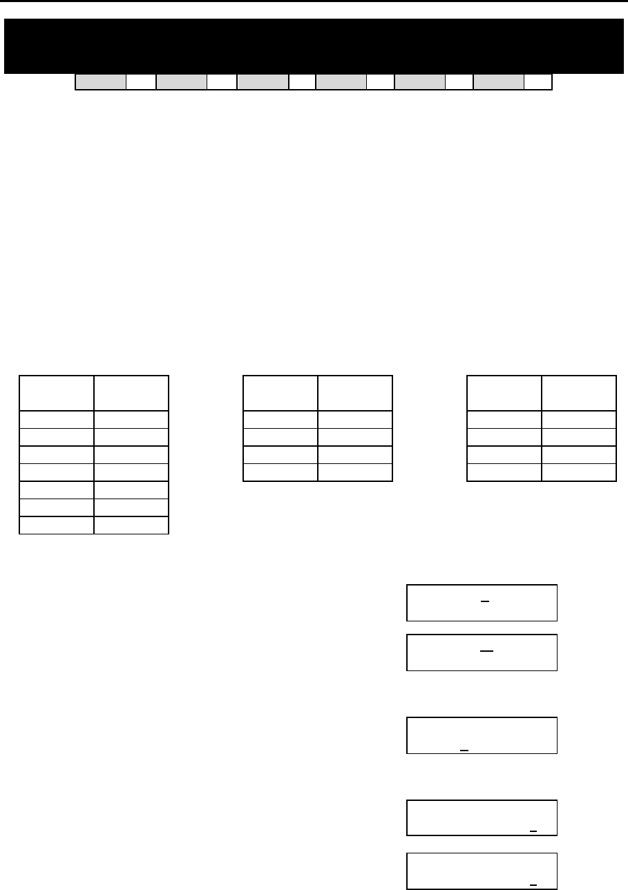
DCS MMC PROGRAMS
COMBINED PROGRAMMING MANUAL NOVEMBER 2001
MMC 711 (Page 1 of 2)
MMC: 711 LCR TIME TABLE
DCS 33 CI 33 CII 33 816 33 408i 33 408 33
This table gives flexibility to the system, through the LCR ROUTES, to allow calls placed at any
given time of day to use the least cost trunk route that is available. When LCR ROUTE ADVANCE
is allowed, it is possible for calls to be placed on more expensive trunks on any given time of
day. There are four possible time entries per day; the start time of the next time period is the end
time of the previous time period.
PROGRAM KEYS
UP & DOWN Used to scroll through options
KEYPAD Used to enter selections
SOFT KEYS Move cursor left and right
SPEAKER Used to store data and advance to next MMC
HOLD Used to clear previous entry
FEATURE KEYS
DAY DIAL TIME
BAND DIAL LCRT DIAL
SUN 0 A 0 LCRT 1
MON 1 B 1 LCRT 2
TUE 2 C 2 LCRT 3
WED 3 D 3 LCRT 4
THU 4
FRI 5
SAT 6
ACTION DISPLAY
1. Open programming and select 711
Display shows
LCR TIME (SUN:A)
HHMM: 0000 LCRT:1
2. Dial day of week (SUN–SAT, e.g., WED)
OR
Press UP or DOWN to make day selection and press
RIGHT soft key
LCR TIME (WED:A)
HHMM: 0000 LCRT:1
3. Dial time band (A–D, e.g., B)
OR
Press UP or DOWN to make selection and press RIGHT
soft key
LCR TIME (WED:B)
HHMM: 0000 LCRT:1
4. Dial time via keypad (24-hour clock format, e.g. 0800)
Cursor moves to LCRT LCR TIME (WED:B)
HHMM:0800 LCRT:1
5. Dial entry 1–4
OR
Press UP or DOWN to select entry and press RIGHT
soft key
LCR TIME (WED:B)
HHMM:0800 LCRT:2

DCS MMC PROGRAMS
COMBINED PROGRAMMING MANUAL NOVEMBER 2001
MMC 711 (Page 2 of 2)
6. Press TRSF to store and exit
OR
Press SPEAKER to store and advance to next MMC
Default Data: Systems can work 24 hours a day and 7 days a week with this default –
DAY TIME BAND TIME LCRT
SUN A 0000 1
B 2359 1
MON A 0000 1
B 2359 1
TUE A 0000 1
B 2359 1
WED A 0000 1
B 2359 1
THU A 0000 1
B 2359 1
FRI A 0000 1
B 2359 1
SAT A 0000 1
B 2359 1
Related Items: MMC 210 Customer On/Off
MMC 400 Customer On/Off Per Trunk
MMC 710 LCR Digit Table
MMC 712 LCR Route Table
MMC 713 LCR Modify Digit Table
DCS MMC PROGRAMS
COMBINED PROGRAMMING MANUAL NOVEMBER 2001
MMC 712 (Page 1 of 2)
MMC: 712 LCR ROUTE TABLE
DCS 33 CI 33 CII 33 816 33 408i 33 408 33
The LCR ROUTE TABLE is responsible for selecting a specific trunk group in the completion of
an outgoing call. This table works in conjunction with LCR DIGIT TABLE, LCR TIME TABLE, LCR
COS TABLE and LCR MODIFIED DIGITS TABLE. After the user dials a valid digit string, the sys-
tem uses the LCR ROUTE TABLE to select a specific predetermined trunk group. A maximum of
16 routes are available beginning with ROUTE NUMBER 1. If more than one trunk group is avail-
able for call completion, the system uses the first designated trunk group and then starts to util-
ise succeeding trunk groups. If all trunk groups are busy in a selected route, call queue becomes
active and allocates trunks as they become available.
PROGRAM KEYS
UP & DOWN Used to scroll through options
KEYPAD Used to enter selections
SOFT KEYS Move cursor left and right
SPEAKER Used to store data and advance to next MMC
HOLD Used to clear previous entry
ACTION DISPLAY
1. Open programming and select 712
Display shows
LCR ROUTE (01:1)
C:1 G:9 M:001
2. Dial LCR ROUTE index number 1–16 (e.g., 05)
OR
Press UP or DOWN to selected index and press
RIGHT soft key to move cursor
LCR ROUTE (05:1)
C:1 G:9 M:005
3. Dial TIME BAND index number 1–4 (e.g., 2)
OR
Press UP or DOWN to selected index and press
RIGHT soft key to move cursor
LCR ROUTE (05:2)
C:1 G:NONE M:---
4. Dial LCR COS number 1–4 (e.g., 4)
OR
Press UP or DOWN to selected COS and press RIGHT
soft key to move cursor
LCR ROUTE (05:2)
C:4 G:NONE M:---
5. Dial TRUNK GROUP access code (e.g., 9)
OR
Press UP or DOWN to selected access code
and press RIGHT soft key to move cursor
LCR ROUTE (05:2)
C:4 G:9 M:---
6. Dial MODIFY DIGITS index number 001–100
(e.g., 050)
OR
Press UP or DOWN to selected index number
and press RIGHT soft key to move cursor
OR
Press RIGHT soft key to leave entry unchanged
LCR ROUTE (05:2)
C:4 G:9 M:050
LCR ROUTE (05:2)
C:4 G:9 M:---

DCS MMC PROGRAMS
COMBINED PROGRAMMING MANUAL NOVEMBER 2001
MMC 712 (Page 2 of 2)
7. Press TRSF to store and exit
OR
Press SPEAKER to store and advance to next MMC
Default Data:
ROUTE TIME BAND COS TRK GRP MODIFY TBL INDEX
01–16 1 1 9 001–016
Related Items: MMC 310 LCR Class Of Service
MMC 710 LCR Digit Table
MMC 711 LCR Time Table
MMC 713 LCR Modify Digit Table
DCS MMC PROGRAMS
COMBINED PROGRAMMING MANUAL NOVEMBER 2001
MMC 713 (Page 1 of 1)
MMC: 713 LCR MODIFY DIGIT TABLE
DCS 33 CI 33 CII 33 816 33 408i 33 408 33
Also referred to as Outdial Rules, this enables the system to add or delete a digit string or single
digit, if needed, to complete a call (e.g. adding a digit “1”). The characters Q and # can also be
entered.
Option Max No. of Digit Entries
Number of digits to delete 15
Insert (before dialling string) 14
Append (after dialling string) 14
Digit String Key
Insert String + Digit String (delete) + Append String
PROGRAM KEYS
UP & DOWN Used to scroll through options
KEYPAD Used to enter selections
SOFT KEYS Move cursor left and right
SPEAKER Used to store data and advance to next MMC
HOLD Used to clear previous entry
ACTION DISPLAY
1. Open programming and select 713
Display shows
LCR MODIFY (001)
NOF DEL DGT:00
2. Enter index number (e.g., 005)
OR
Press UP or DOWN keys to make selection and
press RIGHT soft key to move cursor
LCR MODIFY (005)
NOF DEL DGT:00
3. Enter number of digits to delete (e.g. 2)
OR
Press RIGHT soft key to skip step and move cursor to
step 4
LCR MODIFY (005)
NOF DEL DGT:02
4. Enter digits to be inserted (e.g., 10288)
OR
Press RIGHT soft key to skip step or to store information and
advance to step 5
LCR MODIFY (005)
I:10288
5. Enter digits to be appended (e.g., 45678)
OR
Press RIGHT soft key to skip step or to store
information and return to step 2
LCR MODIFY (005)
A:45678_
6. Press TRSF to store and exit
OR
Press SPEAKER to store and advance to next MMC
Default Data: Depends on software version
Related Items: MMC 710 LCR Digit Table
MMC 711 LCR Time Table
MMC 712 LCR Route Table

DCS MMC PROGRAMS
COMBINED PROGRAMMING MANUAL NOVEMBER 2001
MMC 714 (Page 1 of 3)
MMC: 714 DDI NUMBER AND NAME
TRANSLATION
DCS 33 CI 33 CII 33 816 33 408i 33 408 77
Provides a method of assigning an incoming DDI call through ISDN to a specific station. If you
have specified DDI service with your Network Carrier, you can match each DDI number to spe-
cific stations using this command according to the day or night mode. You also have the option,
when the destination station is busy, of deciding if the call is to be camped on to the destination
station or of clearing the call.
There is an extra option to adjust the number of digits to be compared by skipping the pro-
grammed counts from the first digit point provided by the Network. If there is no matching num-
ber in DDI NUMBER TABLE, the system routes this call to the operator group.
There is a total of 200 entries (DCS/Compact II systems), 50 entries (816 systems), or 20
entries (408i systems). Each entry consists of the following fields:
0 DIGITS (DGT) Digits to be received (max. 12 digits). Wild card (Q) is a valid entry.
1 DAY DEST (D) Destination in day mode. Can be a station, a station group, a trunk
or trunk group. Repeat (B) will be acceptable to bypass.
2 NIGHT DEST (N) Destination in day mode. Can be a station, a station group, a trunk
or a trunk group. Repeat (B) will be acceptable to bypass.
3 CALL WAIT (CW) Toggles YES or NO.
4 DELETE Decides the number of digits not to be translated from the first digit
received. This is useful when the received digits are prefixed with
the same digit(s).
5 NAME Gives a name to an individual entry (11 characters maximum).
Names are written using the keypad in the same way as speed dial names (see MMC 706).
PROGRAM KEYS
UP & DOWN Used to scroll through options
KEYPAD Used to enter selections
SOFT KEYS Move cursor left and right
SPEAKER Used to store data and advance to next MMC
HOLD Used to clear previous entry
DCS MMC PROGRAMS
COMBINED PROGRAMMING MANUAL NOVEMBER 2001
MMC 714 (Page 2 of 3)
ACTION DISPLAY
1. Open programming and select 714
Display shows DID DIGIT (001)
DGT:2QQ
2. Enter valid entry number (e.g. 005 or 05) via dial keypad
OR
Press UP or DOWN key to make selection and press
RIGHT soft key to move cursor
DID DIGIT (005)
DGT:
3. Enter the DDI number (e.g. 4603831) via dial keypad
and press RIGHT soft key to move cursor
(Max. digits is 12)
DID DIGIT (005)
DGT:4603831
4. Enter day destination via dial keypad (e.g. 204)
OR
Press UP or DOWN key to make selection and press
RIGHT soft key to move cursor
DID DIGIT (005)
→D:204 N:B
5. Enter night destination via dial keypad (e.g. 204)
OR
Press UP or DOWN key to make selection and press
RIGHT soft key to move cursor
DID DIGIT (005)
→D:204 N:204
6. Enter 1 for YES (call waiting) or 0 for NO (no call wait-
ing)
OR
Press UP or DOWN key to make selection and press
RIGHT soft key to move cursor
DID DIGIT (005)
CW: NO DELETE:0
7. Enter digits to be deleted via dial keypad (e.g. 3)
OR
Press UP or DOWN key to make selection and press
RIGHT soft key to move cursor
DID DIGIT (005)
CW: NO DELETE:3
8. Enter name using above table and press RIGHT soft
key to return to step 2
DID DIGIT (005)
NAME:_
9. Press TRSF to store and exit
OR
Press SPEAKER to store and advance to next MMC

DCS MMC PROGRAMS
COMBINED PROGRAMMING MANUAL NOVEMBER 2001
MMC 714 (Page 3 of 3)
Default Data:
001 002 003 004
DIGITS* 2QQ 3QQ 5QQ 7QQQ
DAY DEST B B B B
NIGHT DEST B B B B
CALL WAIT NO NO NO NO
DELETE 0 0 0 0
NAME NONE NONE NONE NONE
*For 816 systems, default DIGITS are:
01 02 03
2QQ 5QQ 7QQQ
(Other defaults apply.)
For 408i systems, default DIGITS are:
01 02 03
2Q 5Q 7QQQ
(Other defaults apply.)
Related Items: MMC 419 BRI Option
MMC 420 PRI Option
MMC 421 MSN Digit
DCS MMC PROGRAMS
COMBINED PROGRAMMING MANUAL NOVEMBER 2001
MMC 715 (Page 1 of 2)
MMC: 715 PROGRAMMED STATION
MESSAGE
DCS 33 CI 33 CII 33 816 33 408i 33 408 33
Allows a custom message, up to 16 characters, to be programmed. There are 20 messages al-
lowed in total (01–20). Messages 01–10 are pre-set (see default data) but can be changed by de-
leting and/or typing in new text. Messages 11–20 are blank by default (“EMPTY MESSAGE” may
be displayed if one of these is selected, or the display is blank).
Messages are written via the keypad. Each press of a key selects a character. Pressing a differ-
ent key moves the cursor to the next position. For example, if the message is “In the Showroom,”
press key number “4” three times to get the letter “I.” Then press key number “6” twice to get the
to move the cursor right. Continue selecting characters from the
keypad to complete your message. Press the programmable ”A” key to toggle between upper
and lower case text.
Tip: When the character you want is on the same key as the previous character you typed in, press the UP
key to move the cursor to the right, then select the character.
The # key can be used for the following special characters (in sequence of key presses):
#
space
& ! : ? . , % $ - < > / =
[ ] @ ^ ( ) _ + { } | ; " → `
PROGRAM KEYS
UP & DOWN Used to scroll through options
KEYPAD Used to enter selections
SOFT KEYS Move cursor left and right
SPEAKER Used to store data and advance to next MMC
HOLD Used to clear previous entry
“A” Key #19 (24B keysets) or key #7 (12B keysets) or key #1 (6B key-
sets) toggles upper case and lower case text.
ACTION DISPLAY
1. Open programming and select 715
Display shows
PGM.MESSAGE(01)
IN A MEETING
2. Enter index number (e.g., 11)
OR
Press UP or DOWN arrow to make selection and press
RIGHT soft key to move cursor
PGM.MESSAGE(11)
EMPTY MESSAGE

DCS MMC PROGRAMS
COMBINED PROGRAMMING MANUAL NOVEMBER 2001
MMC 715 (Page 2 of 2)
3. If “EMPTY MESSAGE” is displayed, you can press
HOLD to delete this text. However, this Is optional as
any new message you type will simply overwrite the
displayed text.
Enter new message via the dial keypad using the above
table (maximum 16 characters)
PGM.MESSAGE(11)
In the Showroom
4. Press RIGHT soft key to return to step 2
OR
Press TRSF to store and exit
OR
Press SPEAKER to store and advance to next MMC
Default Data: 10 programmed messages (these can be changed)
01. IN A MEETING
02. OUT ON A CALL
03. OUT TO LUNCH
04. LEAVE A MESSAGE
05. PAGE ME
06. OUT OF TOWN
07. IN TOMORROW
08. RETURN AFTERNOON
09. ON VACATION
10. GONE HOME
Messages 11–20 are blank
Related Items: MMC 115 Set Programmed Message
DCS MMC PROGRAMS
COMBINED PROGRAMMING MANUAL NOVEMBER 2001
MMC 716 (Page 1 of 2)
MMC: 716 UK LCR OPTION
DCS 33 CI 33 CII 33 816 33 408i 33 408 33
Before using this MMC, run MMC 812 to make sure the correct country option (“UK”) has
been selected.
MMC 716 provides UK LCR options.
0 NETWORK CODE Provides secondary network access code when the call is
routed to the secondary network. 16 entries maximum
(each 10 digits maximum in length).
1 PIN CODE Assigns PIN code used when the call is routed to secon-
dary 131 Cable & Wireless network.
2 CCC OPTION Selects Call Cost Option and is related only to 131 Cable
& Wireless service.
3 STATION PIN NO Assigns individual users to selected PIN codes in the sys-
tem.
Note: The second entry may be selected as a primary secondary network. By default, this is 132 (Cable &
Wireless Digital Access). If dialled digits are not matched to the entry in the LCR DIGIT TABLE (MMC 710)
and start with 0, the network code in the second entry will be dialled out by the system prior to transmitting
dialled digits.
PROGRAM KEYS
UP & DOWN Used to scroll through options
KEYPAD Used to enter selections
SOFT KEYS Move cursor left and right
SPEAKER Used to store data and advance to next MMC
HOLD Used to clear previous entry
ACTION DISPLAY
1. Open programming and select 716
Display shows
NETWORK CODE
01:
2. Dial item number (e.g., 1)
OR
Press UP or DOWN key to make selection and press
RIGHT soft key.
PIN CODE
1:
3. Enter index number (e.g., 3)
OR
Press UP or DOWN key to make selection and press
RIGHT soft key
OR
Press LEFT soft key to return to step 2
PIN CODE
3:
4. Enter the desired access via dial keypad and press
RIGHT soft key to enter and return to step 3
PIN CODE
3: QQQQQQ
5. Press TRSF to store and exit
OR
Press SPEAKER to store and advance to next MMC

DCS MMC PROGRAMS
COMBINED PROGRAMMING MANUAL NOVEMBER 2001
MMC 716 (Page 2 of 2)
Default Data:
NETWORK CODE: None
PIN CODE: None
CCC OPTION: None
STATION PIN NO.: All stations are 1
Related Items: MMC 710 LCR Digit Table
MMC 711 LCR Time Table
MMC 712 LCR Route Table
MMC 713 LCR Modify Digit Table
MMC 812 Select Country
DCS MMC PROGRAMS
COMBINED PROGRAMMING MANUAL NOVEMBER 2001
MMC 717 [Compact I] (Page 1 of 1)
MMC: 717 PIN CODE
DCS 77 CI 33 CII 77 816 77 408i 77 408 77
Used to assign the PIN code used when a call is routed to the secondary 131 Cable & Wireless
network.
PROGRAM KEYS
UP & DOWN Used to scroll through options
KEYPAD Used to enter selections
SOFT KEYS Move cursor left and right
SPEAKER Used to store data and advance to next MMC
HOLD Used to clear previous entry
ACTION DISPLAY
1. Open programming and select 717
Display shows
PIN CODE
1:
2. Enter index number (e.g., 2)
OR
Press UP or DOWN key to make selection and press
RIGHT soft key to move cursor
PIN CODE
2:
3. Enter the desired access code via dial keypad (e.g.,
3040506)
Press RIGHT soft key to enter and return to step 2 and
enter another number
PIN CODE
2:3040506
4. Press TRSF to store and exit
OR
Press SPEAKER to store and advance to next MMC
Default Data: None
Related Items: MMC 210 Customer On/Off
MMC 313 Assign PIN Code
MMC 716 Network Code

DCS MMC PROGRAMS
COMBINED PROGRAMMING MANUAL NOVEMBER 2001
MMC 718 (Page 1 of 1)
MMC: 718 MY AREA CODE
Not Used in the UK
DCS MMC PROGRAMS
COMBINED PROGRAMMING MANUAL NOVEMBER 2001
MMC 720 (Page 1 of 1)
MMC: 720 COPY KEY PROGRAMMING
DCS 33 CI 33 CII 33 816 33 408i 33 408 33
For duplicating key assignments from one keyset to another. This can be done on a per-station
basis or on all stations, but not on a group of stations. A limitation is that the original and target
keysets must be of the same type, e.g. both 24B keysets or both 12B keysets. A further condition
is that a Euro keyset can only be copied to another Euro keyset, and a non-Euro type only to an-
other non-Euro type.
PROGRAM KEYS
UP & DOWN Used to scroll through options
KEYPAD Used to enter selections
SOFT KEYS Move cursor left and right
SPEAKER Used to store data and advance to next MMC
HOLD Used to clear previous entry
ANS/RLS Used to select ALL
ACTION DISPLAY
1. Open programming and select 720
Display shows
[201] COPY KEY
FROM:NONE
2. Enter the station number to copy to (e.g., 205)
OR
Press UP or DOWN keys to make selection and
press RIGHT soft key to move cursor
[205] COPY KEY
FROM:NONE
3. Enter station number to copy from (e.g., 203) and cursor
returns to step 2
OR
Press UP or DOWN keys to make selection
[205] COPY KEY
FROM:203
4. Press RIGHT soft key to return to step 2
OR
Press TRSF to store and exit
OR
Press SPEAKER to store and advance to next MMC
Default Data: None
Related Items: MMC 107 Key Extender
MMC 721 Save Station Key Programming
MMC 722 Station Key Programming
MMC 723 System Key Programming
DCS MMC PROGRAMS
COMBINED PROGRAMMING MANUAL NOVEMBER 2001
MMC 721 (Page 1 of 1)
MMC: 721 SAVE STATION KEY
PROGRAMMING
DCS 33 CI 33 CII 33 816 33 408i 33 408 33
Prevents the loss of programmable keys on keysets when testing or replacement is required.
First the data is saved and then the station can be replaced with another station type or the keys
can be reprogrammed to other features. Once testing or replacement is completed, the data can
be restored to the individual station, providing the same keyset type is used.
Options are SAVE and RESTORE.
Note: This program is not to be confused with MMC 315 (Set Relocation). MMC 721 is for saving and restor-
ing the same electronic device type at that port.
PROGRAM KEYS
UP & DOWN Used to scroll through options
KEYPAD Used to enter selections
SOFT KEYS Move cursor left and right
SPEAKER Used to store data and advance to next MMC
ACTION DISPLAY
1. Open programming and select 721
Display shows
[201] SAVE KEY
RESTORE
2. Enter desired station number (e.g., 205)
OR
Press UP or DOWN key to make selection and press
RIGHT soft key
[205] SAVE KEY
RESTORE
3. Press UP or DOWN key to select function (e.g., SAVE)
[205] SAVE KEY
SAVE
4. Press RIGHT soft key to enter and return to step 2
OR
Press TRSF to store and exit
OR
Press SPEAKER to store and advance to next MMC
Default Data: RESTORE
Related Items: MMC 107 Key Extender
MMC 722 Station Key Programming
MMC 723 System Key Programming
DCS MMC PROGRAMS
COMBINED PROGRAMMING MANUAL NOVEMBER 2001
MMC 722 (Page 1 of 3)
MMC: 722 STATION KEY PROGRAMMING
DCS 33 CI 33 CII 33 816 33 408i 33 408 33
Used to customise programmable keys on individual keysets and add-on modules (AOMs). All
systems are provided with default functions for some keys to provide basic operation. For exam-
ple, keys 1 and 2 are set as CALL keys by default because it is recommended that these keys
should always function as CALL keys (but see Note, below). Other keys can be programmed as
described here. You can use the UP and DOWN keys to scroll through the selectable functions
when programming keys (see table at the end of this MMC).
Functions can also be entered via the dial keypad. For example, to assign the OHVA function,
key number 6 can be pressed three times. If the BOSS function is required, press 2 twice for the
first letter B, and then use the UP or DOWN key to change the selection from BARGE to BOSS.
Note: 408/408i systems do not support AOMs and default key functions are different from other systems.
For example, keys 1 and 2 are not set as CALL keys by default as these are not required.
PROGRAM KEYS
UP & DOWN Used to scroll through options
KEYPAD Used to enter selections
SOFT KEYS Move cursor left and right
SPEAKER Used to store data and advance to next MMC
HOLD Used to clear previous entry
ACTION DISPLAY
1. Open programming and select 722
Display shows
[201] KEY (MAST)
01:CALL1 →
OR OR
For 408/408i systems, display shows
(but the programming procedure is the same
as follows)
[21] KEY PROG
01:DT71 →
2. Enter station number (e.g., 205)
OR
Press UP or DOWN key to make selection and press
RIGHT soft key
[205] KEY (MAST)
01:CALL1 →
3. If you have a 408/408i system, or if selected station has
no AOM pair, go to step 4
Enter 0 for MAST, 1 for AOM1 or 2 for AOM2.
OR
Press UP or DOWN key to make selection and press
RIGHT soft key
[205] KEY (MAST)
01:CALL1 →
4. Enter key number (e.g., 18)
OR
Press UP or DOWN key to make selection and press
RIGHT soft key
OR
Press programmable key
[205] KEY (MAST)
18:NONE →_
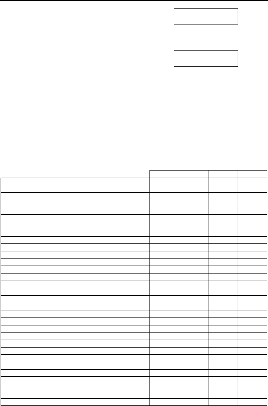
DCS MMC PROGRAMS
COMBINED PROGRAMMING MANUAL NOVEMBER 2001
MMC 722 (Page 2 of 3)
5. Press dial key pad number to make selection
OR
Press UP or DOWN key to make selection and press
RIGHT soft key to advance cursor to step 6 to enter ex-
tender, if required, or to return to step 2
[205] KEY (MAST)
18:NONE →GPIK_
6. If required, enter extender (e.g., 03)
OR
Press UP or DOWN key to make selection and press
RIGHT soft key to return to step 2
[205] KEY (MAST)
18:NONE →GPIK03
7. Press TRSF to store and exit
OR
Press SPEAKER to store and advance to next MMC
Default Data: All systems (except 408/408i)—programmable keys 1 and 2 are set as CALL keys.
You are advised not to change these. Defaults for 408/408i systems are shown in the 408/408i
Installation Manual. Each programmable key can be reprogrammed with one of the functions
listed below.
Programmable Key Function Assignments
(7means a function is not available)
DCS/CII 816 408 408i
AAPLAY: AUTO ATTND MESSAGE PLAY 3 3 7 7
AAREC: AUTO ATTND MESSAGE RECORD 3 3 7 7
AB: ABSENCE 3 3 3 3
ABAND ABANDON DATA 3 3 7 3
ACCT: ACCOUNT 3 3 3 3
ALARM: ALARM RING ANSWER 3 3 7 7
AN/RLS ANSWER/RELEASE 3 3 3 3
BARGE: BARGE-IN 3 3 3 3
BLOCK: OHVA BLOCK 3 3 3 3
BOSS: BOSS / SECRETARY 3 3 3 3
CALL: CALL BUTTON 3 3 3 3
CAMP: STATION CAMP ON 3 3 3 3
CANMG: MESSAGE CANCEL 3 3 3 3
CBK: CALLBACK 3 3 3 3
CLIP: CLIP 3 3 7 3
CONF: CONFERENCE 3 3 3 3
CR: CALL RECORD 3 7 7 7
CS: UCD CALL WAITING STATUS 3 3 7 7
CSNR: CLIP SAVE NUMBER REDIAL 3 3 7 3
DICT: DICTATION 3 3 3 3
DIR: DIRECTORY 3 3 3 3
DLOCK: DOOR LOCK 3 3 3 3
DND: DO NOT DISTURB 3 3 3 3
DP: DIRECT PICK UP 3 3 3 3
DROP: TRANSFER CALL DROP 3 3 3 3
DS: DIRECT STATION SELECT 3 3 3 3
DT: DIRECT TRUNK SELECT 3 3 3 3
EXTMIC: EXTERNAL MICROPHONE 3 3 3 3
FAUTO: FORCED AUTO ANSWER 3 3 3 3
FLASH: FLASH 3 3 3 3
FWRD: CALL FORWARD 3 3 3 3

DCS MMC PROGRAMS
COMBINED PROGRAMMING MANUAL NOVEMBER 2001
MMC 722 (Page 3 of 3)
DCS/CII 816 408 408i
GPIK: GROUP PICK UP 3 3 3 3
HDSET: HEADSET MODE ON/OFF 3 3 3 3
HLDPK: HOLD PICK UP 3 3 3 3
IG: IN/OUT OF GROUP 3 3 3 3
INQIRE: CLIP INQUIRE 3 3 7 3
ISPY: CLIP SPY 3 3 7 3
LCR: LEAST COST ROUTING 3 3 3 3
LISTN: GROUP LISTENING 3 3 3 3
LNR: LAST NUMBER REDIAL 3 3 3 3
MMPA: MEET ME PAGE ANSWER 3 3 3 3
MMPG: MEET ME PAGE 3 3 3 3
MSG: MESSAGE 3 3 3 3
MUTE: MUTE 3 3 3 3
NEW: NEW CALL 3 3 3 3
NIGHT: NIGHT SERVICE 3 3 3 3
NND: CLIP NAME/NUMBER/DATE 3 3 7 3
NXT: CLIP NEXT 3 3 7 3
OHVA: OFF-HOOK VOICE ANNOUNCE 3 3 3 3
OPER: OPERATOR 3 3 3 3
PAGE: PAGE 3 3 3 3
PAGPK: PICKUP PAGE HOLD 3 3 3 3
PARK: CALL PARK/RETRIEVE 3 3 3 3
PAUSE: PAUSE 3 3 3 3
PMSG: PROGRAMMED STATION MESSAGE 3 3 3 3
REJECT: OHVA REJECT 3 3 3 3
RETRY: AUTO REDIAL ON BUSY 3 3 3 3
REVW: REVIEW (CLIP) 3 3 7 3
SETMG: SET MESSAGE W/O RING 3 3 3 3
SG: STATION GROUP 3 3 3 3
SNR: SAVED NUMBER REDIAL 3 3 3 3
SP: SUPERVISOR OF UCD 3 3 7 7
SPD: SPEED DIAL 3 3 3 3
SPKR: SPEAKER 3 3 3 3
STORE: STORE (CLIP) 3 3 7 3
TG: TRUNK GROUP 3 3 3 3
TIMER: TIMER 3 3 3 3
TRSF: TRANSFER 3 3 3 3
UA: UNIVERSAL ANSWER 3 3 3 3
VDIAL: VOICE DIALLER ACCESS 3 7 7 7
VG: VOICE MAIL GROUP 3 7 7 7
VMADM: VOICE MAIL ADMINISTRATION 3 7 7 7
VMAME: VOICE MAIL ANSWERING MACHINE
EMULATION 3 7 7 7
VM: VOICE MAIL MEMO 3 7 7 7
VMMSG: VOICE MAIL MESSAGE 3 7 7 7
VREC: RECORD KEY FOR VOICE DIALLER 3 7 7 7
VT: VOICE MAIL TRANSFER 3 3 3 3
Related Items: MMC 107 Key Extender
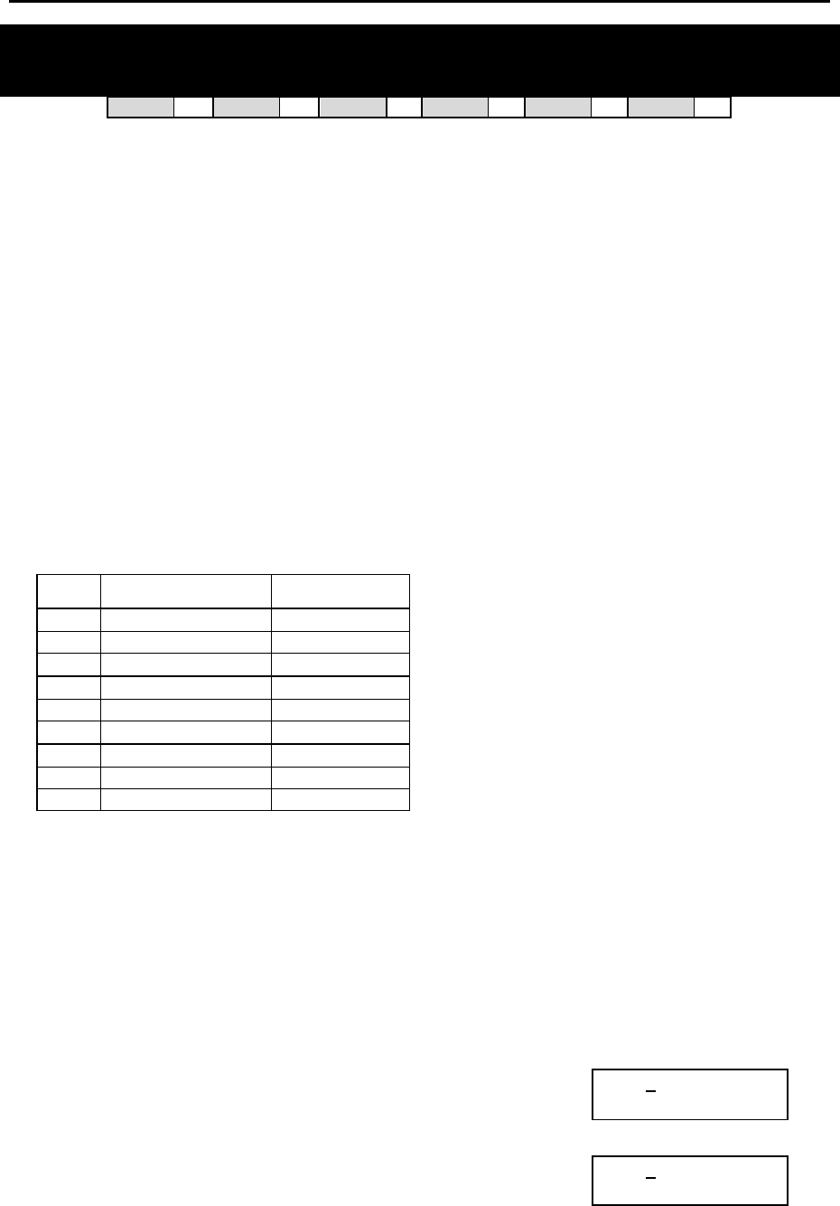
DCS MMC PROGRAMS
COMBINED PROGRAMMING MANUAL NOVEMBER 2001
MMC 723 (Page 1 of 3)
MMC: 723 SYSTEM KEY PROGRAMMING
DCS 33 CI 33 CII 33 816 33 408i 33 408 33
This MMC is similar to MMC 722, Station Key Programming. The difference is that MMC 723 pro-
grams keys for all stations rather than individual stations.
All systems are provided with default functions for some keys to provide basic operation. For
example, keys 1 and 2 are set as CALL keys by default because it is recommended that these
keys should always function as CALL keys (but see Note, below). Other keys can be
programmed as described here. You can use the UP and DOWN keys to scroll through the
selectable functions when programming keys (see table at the end of this MMC).
Functions can also be entered via the dial keypad. For example, to assign the OHVA function,
key number 6 can be pressed three times. If the BOSS function is required, press 2 twice for the
first letter B, and then use the UP or DOWN key to change the selection from BARGE to BOSS.
Note: Default key functions are different for 408/408i systems compared to all other systems. For example,
keys 1 and 2 are not set as CALL keys by default as these are not required.
Programming in MMC 723 is also done on the basis of keyset type (12-button, 24-button, etc).
TYPE OF SET
Dial DCS/CII/816 408/408i
0 24-BTN 24-BTN
1 12-BTN 24-BTN EURO
2 6-BTN 12-BTN
3 – 6-BTN
4 48-BTN AOMS 28-BTN
5 – 18-BTN
6 28-BTN 8-BTN
7 18-BTN 24B SIMPLE
8 8-BTN
PROGRAM KEYS
UP & DOWN Used to scroll through options
KEYPAD Used to enter selections
SOFT KEYS Move cursor left and right
SPEAKER Used to store data and advance to next MMC
HOLD Used to clear previous entry
ACTION DISPLAY
1. Open programming and select 723
Display shows
TYPE:24 BTN SETS
01:CALL1→
OR OR
For 408/408i systems, display shows
(but programming procedure is the same as follows)
TYPE:24 BTN SETS
01:DT71 →
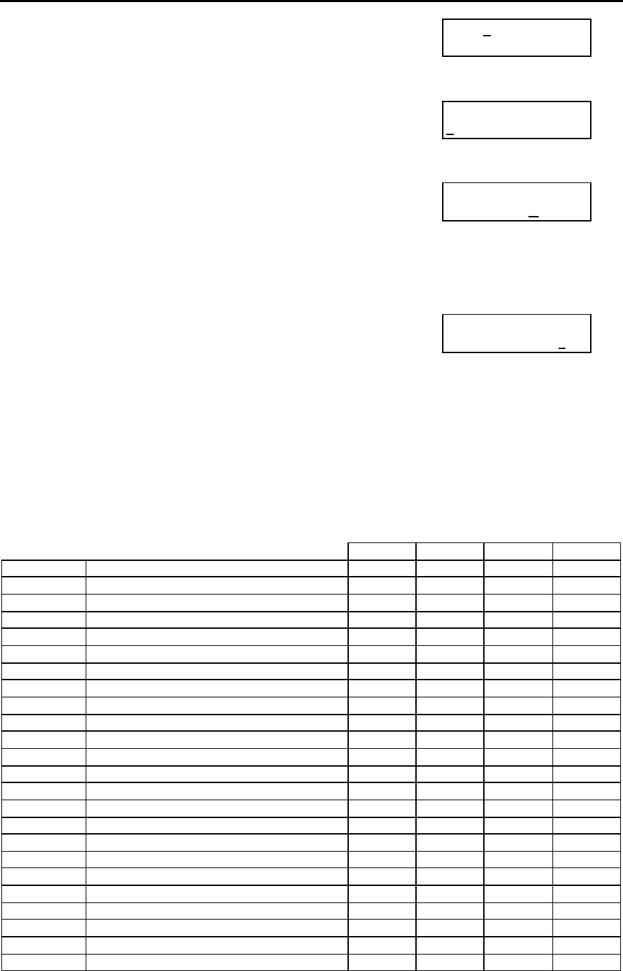
DCS MMC PROGRAMS
COMBINED PROGRAMMING MANUAL NOVEMBER 2001
MMC 723 (Page 2 of 3)
2. Enter keyset type via dial keypad, using table above ( e.g.,1)
OR
Press UP or DOWN key to make selection and press RIGHT
soft key
TYPE:12 BTN SETS
01:CALL1→
3. Enter key number (e.g., 12)
OR
Press UP or DOWN key to make selection and press RIGHT
soft key
TYPE:12 BTN SETS
12:DS →
4. Press dial keypad to select function
OR
Press UP or DOWN key to make selection and press RIGHT
soft key to advance cursor to step 5 to enter extender, if re-
quired
OR
Press LEFT soft key to return to step 3
TYPE:12 BTN SETS
12:DS →GPIK
5. If required, enter extender (e.g.,03)
OR
Press UP or DOWN key to make selection and press RIGHT
soft key to return to step 2
TYPE:12 BTN SETS
12:DS →GPIK03
6. Press TRSF to store and exit
OR
Press SPEAKER to store and advance to next MMC
Default Data: See MMC 722.
Programmable Key Function Assignments
(7 means a function is not available)
DCS/CII 816 408 408i
AAPLAY: AUTO ATTND MESSAGE PLAY 3 3 7 7
AAREC: AUTO ATTND MESSAGE RECORD 3 3 7 7
AB: ABSENCE 3 3 3 3
ABAND ABANDON DATA 3 3 7 3
ACCT: ACCOUNT 3 3 3 3
ALARM: ALARM RING ANSWER 3 3 7 7
AN/RLS ANSWER/RELEASE 3 3 3 3
BARGE: BARGE-IN 3 3 3 3
BLOCK: OHVA BLOCK 3 3 3 3
BOSS: BOSS / SECRETARY 3 3 3 3
CALL: CALL BUTTON 3 3 3 3
CAMP: STATION CAMP ON 3 3 3 3
CANMG: MESSAGE CANCEL 3 3 3 3
CBK: CALLBACK 3 3 3 3
CLIP: CLIP 3 3 7 3
CONF: CONFERENCE 3 3 3 3
CR: CALL RECORD 3 7 7 7
CS: UCD CALL WAITING STATUS 3 3 7 7
CSNR: CLIP SAVE NUMBER REDIAL 3 3 7 3
DICT: DICTATION 3 3 3 3
DIR: DIRECTORY 3 3 3 3
DLOCK: DOOR LOCK 3 3 3 3
DND: DO NOT DISTURB 3 3 3 3
DP: DIRECT PICK UP 3 3 3 3

DCS MMC PROGRAMS
COMBINED PROGRAMMING MANUAL NOVEMBER 2001
MMC 723 (Page 3 of 3)
DCS/CII 816 408 408i
DROP: TRANSFER CALL DROP 3 3 3 3
DS: DIRECT STATION SELECT 3 3 3 3
DT: DIRECT TRUNK SELECT 3 3 3 3
EXTMIC: EXTERNAL MICROPHONE 3 3 3 3
FAUTO: FORCED AUTO ANSWER 3 3 3 3
FLASH: FLASH 3 3 3 3
FWRD: CALL FORWARD 3 3 3 3
GPIK: GROUP PICK UP 3 3 3 3
HDSET: HEADSET MODE ON/OFF 3 3 3 3
HLDPK: HOLD PICK UP 3 3 3 3
IG: IN/OUT OF GROUP 3 3 3 3
INQIRE: CLIP INQUIRE 3 3 7 3
ISPY: CLIP SPY 3 3 7 3
LCR: LEAST COST ROUTING 3 3 3 3
LISTN: GROUP LISTENING 3 3 3 3
LNR: LAST NUMBER REDIAL 3 3 3 3
MMPA: MEET ME PAGE ANSWER 3 3 3 3
MMPG: MEET ME PAGE 3 3 3 3
MSG: MESSAGE 3 3 3 3
MUTE: MUTE 3 3 3 3
NEW: NEW CALL 3 3 3 3
NIGHT: NIGHT SERVICE 3 3 3 3
NND: CLIP NAME/NUMBER/DATE 3 3 7 3
NXT: CLIP NEXT 3 3 7 3
OHVA: OFF-HOOK VOICE ANNOUNCE 3 3 3 3
OPER: OPERATOR 3 3 3 3
PAGE: PAGE 3 3 3 3
PAGPK: PICKUP PAGE HOLD 3 3 3 3
PARK: CALL PARK/RETRIEVE 3 3 3 3
PAUSE: PAUSE 3 3 3 3
PMSG: PROGRAMMED STATION MESSAGE 3 3 3 3
REJECT: OHVA REJECT 3 3 3 3
RETRY: AUTO REDIAL ON BUSY 3 3 3 3
REVW: REVIEW (CLIP) 3 3 7 3
SETMG: SET MESSAGE W/O RING 3 3 3 3
SG: STATION GROUP 3 3 3 3
SNR: SAVED NUMBER REDIAL 3 3 3 3
SP: SUPERVISOR OF UCD 3 3 7 7
SPD: SPEED DIAL 3 3 3 3
SPKR: SPEAKER 3 3 3 3
STORE: STORE (CLIP) 3 3 7 3
TG: TRUNK GROUP 3 3 3 3
TIMER: TIMER 3 3 3 3
TRSF: TRANSFER 3 3 3 3
UA: UNIVERSAL ANSWER 3 3 3 3
VDIAL: VOICE DIALLER ACCESS 3 7 7 7
VG: VOICE MAIL GROUP 3 7 7 7
VMADM: VOICE MAIL ADMINISTRATION 3 7 7 7
VMAME: VOICE MAIL ANSWERING MACHINE
EMULATION 3 7 7 7
VM: VOICE MAIL MEMO 3 7 7 7
VMMSG: VOICE MAIL MESSAGE 3 7 7 7
VREC: RECORD KEY FOR VOICE DIALLER 3 7 7 7
VT: VOICE MAIL TRANSFER 3 3 3 3
Related Items: MMC 107 Key Extender
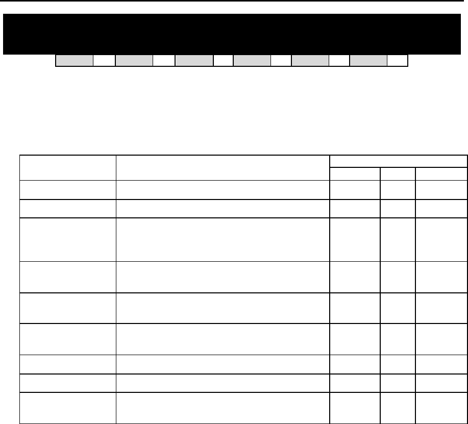
DCS MMC PROGRAMS
COMBINED PROGRAMMING MANUAL NOVEMBER 2001
MMC 724 (Page 1 of 2)
MMC: 724 DIAL NUMBERING PLAN
DCS 33 CI 33 CII 33 816 33 408i 33 408 33
The system comes with a range of acceptable numbering plans set as default. This MMC allows
the system installer to customise feature codes and dialling plans. An error message is also pro-
vided in case an access/feature code is duplicated.
The following options can be selected. (N/A=not applicable.)
Dial
Option Description DCS/CII 816 408/408i
STN DIAL NO. Determines the station port dialling numbers 0 0 0
TRK DIAL NO. Determines the trunk port dialling numbers 1 1 1
AA/VD DIAL NO.
(816=AA DIAL
NO.)
Determines the auto attendant/voice dialler
port dialling numbers 2 2 N/A
MISC DIAL NO. Determines the miscellaneous port dialling
numbers (e.g. MOH) 3 3 2
STNG DIAL NO. Determines the station group dialling num-
bers 4 4 3
TRKG DIAL NO. Determines the trunk group dialling num-
bers 5 5 4
FEAT DIAL NO. Determines the feature codes 6 6 5
S0 STN DIAL NO. Determines the S0 station dialling number 7 7 6*
DECT STN DIAL
NO. Determines the DECT station dialling num-
bers 8 N/A N/A
* 408i systems only
If changing feature codes using the FEAT DIAL NO option, you can use the UP and DOWN keys
to scroll through selectable features. Features can also be entered via the dial keypad. For ex-
ample, for OHVA, the number 6 would be pressed three times. If Block Code is required, press 2
twice for BARGE and then use the UP key to select BLOCK. The example shown below de-
scribes the use of this option.
PROGRAM KEYS
UP & DOWN Used to scroll through options
KEYPAD Used to enter selections
SOFT KEYS Move cursor left and right
SPEAKER Used to store data and advance to next MMC
HOLD Used to clear previous entry

DCS MMC PROGRAMS
COMBINED PROGRAMMING MANUAL NOVEMBER 2001
MMC 724 (Page 2 of 2)
ACTION DISPLAY
1. Open programming and select 724
Display shows (e.g. for Compact II)
STN DIAL NUMBER
BASE01:201 →
2. Enter option number 0-8 (e.g., 6)
OR
Press UP or DOWN key to make selection and press
RIGHT soft key.
FEAT DIAL NUMBER
ABAND: 64→
3. Use dial keypad to select feature (e.g. DICT)
OR
Press UP or DOWN key to make selection and press
RIGHT soft key to advance cursor
FEAT DIAL NUMBER
DICT :NONE→_
4. Enter digits (e.g., 68) via dial keypad
FEAT DIAL NUMBER
DICT :NONE→68
5. Press LEFT soft key to enter change and continue to
make changes
OR
Press RIGHT soft key to enter and return to step 2
If an error message appears indicating duplication of
access code:
Enter 1 for YES (change) OR 0 for NO (no change)
SAME DIAL EXIST
CHANGE? Y:1,N:0
6. Press TRSF to store and exit
OR
Press SPEAKER to store and advance to next MMC
Default Data: Feature Codes
ABAND 64 HDSET None SNR 17
ABS None HLDPK 12 SPEED 16
ACCT 47 HOLD 11 UA 67
ALMCLR 57 IG 53 VDIAL 681
AUTH ∗ LCR # VMADM None
BARGE None LISTN None VMAME None
BLOCK None LNR 19 VMMEMO None
BOSS None MMPA 56 VMMSG None
CAMP 45 MMPG 54 VREC 682
CANMG 42 MSG 43 WCOS 59
CBK 44 MYGRPK None
CONF 46 NEW None
CR None NIGHT None
DICT None OHVA None
DIR None OPER 0 (9)
DIRPK 65 PAGE 55
DISALM 58 PAGPK 10
DLOCK 13 PARK None
DND 40 PAUSE None
DNDOVER None PMSG 48
FAUTO 14 REJECT None
FLASH 49 SELFID None
FWD 60 SETMG 41
GRPK 66 SLTMMC 15
Related Items: All programs and features

DCS MMC PROGRAMS
COMBINED PROGRAMMING MANUAL NOVEMBER 2001
MMC 725 (Page 1 of 3)
MMC: 725 SMDR OPTIONS
DCS 33 CI 33 CII 33 816 33 408i 33 408 33
Allows the system administrator to select the information to be printed on the SMDR report. The
following options may be selected. All have YES/NO options (YES=print) except where a new
value or directory name is required.
00 PAGE HEADER Determines whether a page header prints at the top of each
page. This would normally be turned off if SMDR is being sent to
a call accounting machine.
01 LINE PER PAGE Selects the length of each page to determine when to print the
SMDR header. The number of lines is in the range 01–99.
02 INCOMING CALL Determines whether incoming calls print on SMDR.
03 OUTGOING CALL Determines whether outgoing calls print on SMDR.
04 AUTHORISE CODE Determines whether authorisation codes print on SMDR.
05 SMDR START TIME Determines whether valid calls will include the minimum call time
in total call duration (set in MMC 501).
06 IN/OUT GROUP Allows a message, IN GROUP or OUT GROUP, to be printed in
the Digits Dialled column each time a station enters or leaves a
group.
07 DND CALL Allows a message, DND ON or DND OFF, to be printed in the
Digits Dialled column each time a station enters or leaves DND.
08 WAKE-UP CALL Determines whether stations receiving an alarm reminder call
print on SMDR.
09 DIRECTORY NAME Allows the system administrator to enter a 16-character name
which will appear on the SMDR header.
10 CALLER ID DATA Can be selected to print CLIP data received from the C.O. on
incoming ISDN calls. This option requires the use of a 132-
column printer or an 80-column printer set for condensed print.
(Not available on 408 systems.)
11 ABANDON CALL If this option is set to YES, unanswered calls will print on SMDR.
(Not available on 408 systems.)
13 NO. OF DIAL MASK Number of dialled digits not to be printed (00–18)
14 DID NUM/NAME Determines whether DDI number and name print on SMDR. (Not
available on 408 systems.)
The DIRECTORY NAME that appears on the SMDR header is written using the keypad. Pressing
a key selects a character and moves the cursor to the next position. For example, if the directory
name is “SAM SMITH,” press the number “7” four times to get the letter “S.” Now press the
number “2” once to get the letter “A.” Continue selecting characters from the keypad to complete
the name. Press the programmable ”A” key to toggle between upper and lower case text.
Tip: When the character you want is on the same key as the previous character you typed in, press the UP
key to move the cursor to the right, and enter the new character.
DCS MMC PROGRAMS
COMBINED PROGRAMMING MANUAL NOVEMBER 2001
MMC 725 (Page 2 of 3)
The # key can be used for the following special characters (in sequence of key presses):
#
space
& ! : ? . , % $ - < > / =
[ ] @ ^ ( ) _ + { } | ; " → `
PROGRAM KEYS
UP & DOWN Used to scroll through options
KEYPAD Used to enter selections
SOFT KEYS Move cursor left and right
SPEAKER Used to store data and advance to next MMC
“A” Key #19 (24B keyset) or key #7 (12B keyset) or key #1 (6B keyset)
toggles upper and lower case text.
Exa mple 1: Switching options on (yes=print) or off (no=do not print)
ACTION DISPLAY
1. Open programming and select 725
Display shows
PAGE HEADER
PRINT : YES
2. Dial the option number (e.g. 00)
OR
Use the UP and DOWN keys to scroll through
options and press RIGHT soft key
PAGE HEADER
PRINT : YES
3. Use the UP and DOWN keys to select YES or NO
and press the RIGHT soft key to save
the data and return to step 2
PAGE HEADER
PRINT : NO
4. After all desired options have been selected and set,
press TRSF to exit
OR
Press SPEAKER to exit and advance to next MMC
Example 2: Changing no. of lines per page
ACTION DISPLAY
1. Open programming and select 725
Display shows
PAGE HEADER
PRINT : YES
2. Dial the option number 01
OR
Use the UP and DOWN keys to select and press
RIGHT soft key
LINE PER PAGE
66 LINE / PAGE
3. Enter the number of lines per page in the range 01–99
(e.g., 50)
OR
Use the UP and DOWN keys to change the
number of lines and press the RIGHT soft key to save
the data and return to step 2
LINE PER PAGE
50 LINE / PAGE

DCS MMC PROGRAMS
COMBINED PROGRAMMING MANUAL NOVEMBER 2001
MMC 725 (Page 3 of 3)
4. After all desired options have been selected and set,
press TRSF to exit
OR
Press SPEAKER to exit and advance to next MMC
Default Data:
Page Header: Yes DND Call: Yes
Line Per Page: 66 Wake-Up Call: Yes
Incoming Call: Yes Directory Name: None
Outgoing Call: Yes Caller ID Data: Yes
Authorise Code: Yes Abandon Call: Yes
SMDR Start Time: Yes No. of Dial Mask: 00
In/Out Group: Yes DID Num/Name: Yes
Related Items: MMC 300 Customer On/Off Per Station

DCS MMC PROGRAMS
COMBINED PROGRAMMING MANUAL NOVEMBER 2001
MMC 726 (Page 1 of 3)
MMC: 726 VM/AA OPTIONS
DCS 33 CI 33 CII 33 816 33 408i 33 408 33
Provides a flexible means of setting in-band signalling for voice mail or auto attendant parame-
ters. There are eight main options for programming and several sub-options to customise the
application. Simple YES/NO, numeric and alpha characters are required for setting VM/AA.
The following options may be selected for VM/AA operation:
0 EXT FOR DN1 DTMF information for the station that called the VM/AA
port station which is forwarded to VM/AA port.
1 TRK FOR DN1 DTMF information for the trunk that called the VM/AA
port.
2 EXT FOR DN2 DTMF information for the station that originated the call
to a station which is forwarded to a VM/AA port.
3 TRK FOR DN2 DTMF information for the trunk that called a station for-
warded to a VM/AA port.
4 SEPARATOR In cases where DN2 is used, this specific digit is sent
between the DN1 and the DN2 information. Both DN1
and DN2 must be set to YES for SEPARATOR to be sent.
5 DISCONNECT SIGNAL This signal is sent when the calling station or C.O. line
hangs up.
6 CALL TYPE ID Under this VM/AA option are several customising appli-
cations:
0 DIRECT CALL A call originating directly from another station in the sys-
tem.
1 ALL FWD CALL This indicates that a call was forwarded to the VM/AA
port from a station with CALL FORWARD ALL set.
2 BSY FWD CALL This indicates that a call was forwarded to the VM/AA
port from a station with CALL FORWARD BUSY set.
3 NOA FWD CALL This indicates that a call was forwarded to the VM/AA
port from a station with CALL FORWARD NO ANSWER
set.
4 RECALL A call is recalling the VM/AA port after being transferred
and not answered.
5 DIR TRK CALL A C.O. call has gone directly to VM/AA (e.g., trunk 717
DIL to VM/AA).
6 OVERFLOW A call has OVERFLOWED to the VM/AA port from a sta-
tion group.
7 DID CALL A DDI call has called the VM/AA port.
8 MESSAGE CALL A message button or message reply feature code has
been used to call the VM/AA port.
7 PROGRESS TONE ID DTMF digits can be sent in place of normal system
tones. Digits can be assigned to the following tones:
DCS MMC PROGRAMS
COMBINED PROGRAMMING MANUAL NOVEMBER 2001
MMC 726 (Page 2 of 3)
TONES
0. DIAL TONE
1. BUSY TONE
2. RINGBACK TONE
3. DND NO MORE
4. HDSET ANSWER
5. SPKER ANSWER
Note: The call progress tones will automatically be set to the default values if the SMDI VMS SET option in
MMC 210 is turned on.
PROGRAM KEYS
UP & DOWN Used to scroll through options
KEYPAD Used to enter selections
SOFT KEYS Move cursor left and right
SPEAKER Used to store data and advance to next MMC
HOLD Used in some fields where a value is entered or deleted.
“A” Used to input alpha character "A"
”B” Used to insert alpha character "B"
”C” Used to insert alpha character "C"
Keys “A”–“F” are keys #19–24 (24B keysets) or keys #7–12 (12B keysets) or keys #1–6 (6B
keysets)
ACTION DISPLAY
1. Open programming and select 726
Display shows EXT FOR DN1
YES
2. Enter the option number from above list (e.g., 4
— for other options, see steps 4–11) SEPARATOR
NO
OR
Press UP or DOWN key to make selection
Press LEFT soft key to move cursor
3. Enter 1 for YES or 0 for NO
OR SEPARATOR
YES
Press UP or DOWN key for selection
Press RIGHT soft key to return to step 2
4. If option 0 is selected at step 2 EXT FOR DN1
YES
5. If option 1 is selected at step 2 TRK FOR DN1
YES
6. If option 2 is selected at step 2
EXT FOR DN2
NO
7. If option 3 is selected at step 2 TRK FOR DN2
NO

DCS MMC PROGRAMS
COMBINED PROGRAMMING MANUAL NOVEMBER 2001
MMC 726 (Page 3 of 3)
8. If option 4 is selected at step 2
(A valid entry consists of digits 0–9 or alpha
characters A–C)
SEPARATOR
NO
9. If option 5 is selected at step 2
(A valid entry consists of digits 0–9 or alpha DISCONECT SIGNAL
C
characters A–C)
10. If option 6 is selected at step 2
(A valid entry consists of digits 0–9 or alpha CALL TYPE ID
DIRECT CALL : NO
characters A–C)
See above list under CALL TYPE ID options list
11. If option 7 is selected at step 2
(A valid entry consists of digits 0–9 or alpha PROGRESS TONE ID
DIAL TONE :NO
characters A–C)
See above list under PROGRESS TONE ID
12. Press TRSF to store and exit
OR
Press SPEAKER to store and advance to next MMC
Default Data:
EXT FOR DN1 = Yes
TRK FOR DN1 = Yes
EXT FOR DN2 = No
TRK FOR DN2 = No
SEPARATOR = No
DISCONNECT SIGNAL = C
CALL TYPE ID:
DIRECT CALL 1
ALL FWD CALL 2
BSY FWD CALL 3
NOA FWD CALL 4
RECALL 5
DIR TRK CALL 6
OVERFLOW 7
DDI CALL 8
MESSAGE CALL 9
PROGRESS TONE ID = No (for all)
Related Items: MMC 207 Assign VM/AA Port
DCS MMC PROGRAMS
COMBINED PROGRAMMING MANUAL NOVEMBER 2001
MMC 727 (Page 1 of 1)
MMC: 727 SYSTEM VERSION DISPLAY
DCS 33 CI 33 CII 33 816 33 408i 33 408 33
This is a read-only MMC. Used for system card version and date display only. The first display is the
system ROM version. Press UP or DOWN key to show versions for other cards installed.
Version displays take the format:
YY.MM.DD Version #
Where YY=Year, MM=Month, DD=Day, Version #= version number (e.g. V1.00)
PROGRAM KEYS
UP & DOWN Used to scroll through options
SPEAKER Used to advance to next MMC
ACTION DISPLAY
1. Open programming and select 727
Display shows date and version
ROM VERSION
’01. 02. 16. V6.25
2. Press UP or DOWN key to select other
installed cards (e.g. Misc card)
MISC. VER:MISC
’96. 10. 02 V3.0
3. Press TRSF to exit
OR
Press SPEAKER to advance to next MMC
Note: If a particular card is not installed, the LCD shows either ‘NO {card type} CARD’ or ‘NO INSTALL CARD.’ If
there is no version data, you see ‘NO VERSION DATA’.
Default Data: Installed card version and date
Related Items: None
DCS MMC PROGRAMS
COMBINED PROGRAMMING MANUAL NOVEMBER 2001
MMC 728 (Page 1 of 2)
MMC: 728 CLIP TRANSLATION TABLE
DCS 33 CI 33 CII 33 816 33 408i 33 408 77
Allows the system administrator or technician to associate a CLIP number received from the cen-
tral office with a name programmed in this translation table. If there is no match between a re-
ceived number and a name in this table, “no CLIP name” is displayed.
DCS – translation table consists of 250 entries, each comprising an 11-digit telephone number
and a 16-digit name.
Compact II and 816 – translation table consists of 200 entries, each comprising a 16-digit tele-
phone number and a 16-digit name.
408i – translation table consists of 100 entries, each comprising a 14-digit telephone number and
a 16-digit name.
Names are written using the keypad. Each key press selects a character and moves the cursor to
the next position. For example, if the name is “SAM SMITH”, press the number “7” four times to
get the letter “S”. Now press the number “2” once to get the letter “A” Continue selecting charac-
ters from the keypad to complete your name. Press the programmable “A” key to toggle between
upper and lower case text.
Tip: When the character you want is on the same key as the previous character you typed in, press the UP
key to move the cursor to the right, then select the character.
The # key can be used for the following special characters (in sequence of key presses):
#
space
& ! : ? . , % $ - < > / =
[ ] @ ^ ( ) _ + { } | ; " → `
PROGRAM KEYS
UP & DOWN Used to scroll through options
KEYPAD Used to enter selections
SOFT KEYS Move cursor left and right
SPEAKER Used to store data and advance to next MMC
HOLD Used to clear previous entry
“A” Key #19 (24B keyset) or key #7 (12B keyset) or key #1 (6B keyset)
toggles upper and lower case text.

DCS MMC PROGRAMS
COMBINED PROGRAMMING MANUAL NOVEMBER 2001
MMC 728 (Page 2 of 2)
ACTION DISPLAY
1. Open programming and select 728
Display shows first entry
CLIP XLAT (001)
DGT:
2. Dial entry number (e.g., 005)
OR
Press UP or DOWN key to select and press RIGHT
soft key
CLIP XLAT (005)
DGT:_
3. Enter telephone number and press RIGHT soft key
to advance to name entry
OR
Enter telephone number and press LEFT soft key
to return to step 2
CLIP XLAT (005)
DGT:3054264100
4. Enter associated name as described above and
press RIGHT or LEFT soft key to return to step 2
OR
Press SPEAKER to save and advance to next MMC
OR
Press TRSF to save and exit programming
CLIP XLAT (005)
SAMSUNG TELECOMS
Default Data: None
Related Items: None
DCS MMC PROGRAMS
COMBINED PROGRAMMING MANUAL NOVEMBER 2001
MMC 730 (Page 1 of 1)
MMC: 730 AA RECORD GAIN
DCS 33 CI 77 CII 33 816 33 408i 77 408 77
Used to control AA record gain. Note that AA card port numbers differ between systems (see Part
2, section 2.3, System Configuration: Quick Reference).
PROGRAM KEYS
UP & DOWN Used to scroll through options
KEYPAD Used to enter selections
SOFT KEYS Move cursor left and right
SPEAKER Used to store data and advance to next MMC
HOLD Used to clear previous entry
ACTION DISPLAY
1. Open programming and select 730
Display shows (e.g. for Compact II / 816)
[381] AAREC.GAIN
REC.GAIN:+0.0
2. Dial AA number (first port in card, e.g 385)
OR
Press UP or DOWN to select and press RIGHT soft key
[385] AAREC.GAIN
REC.GAIN:+0.0
3. Press UP or DOWN to select record gain and press
RIGHT soft key
[385] AAREC.GAIN
REC.GAIN:+1.0
4. Press TRSF to store and exit
OR
Press SPEAKER to store and advance to next MMC.
Default Data: +0.0 dB
Related Items: None
DCS MMC PROGRAMS
COMBINED PROGRAMMING MANUAL NOVEMBER 2001
MMC 731 (Page 1 of 1)
MMC: 731 AA RAM CLEAR
DCS 33 CI 77 CII 33 816 33 408i 77 408 77
Used for clearing AA RAM on a per-AA card basis. The system only accepts the first port as a
port field and the LCD shows its selection. This will erase the whole message that has been pro-
grammed previously on the selected card.
Note that AA card port numbers differ between systems (see Part 2, section 2.3, System
Configuration: Quick Reference).
PROGRAM KEYS
UP & DOWN Used to scroll through options
KEYPAD Used to enter selections
SOFT KEYS Move cursor left and right
SPEAKER Used to store data and advance to next MMC
HOLD Used to clear previous entry
ACTION DISPLAY
1. Open programming and select 731
Display shows (e.g. for Compact II / 816) [381] RAM CLEAR
CLR RECORDED?NO
2. Dial AA number (e.g. 381)
OR
Press UP or DOWN to make selection and press
RIGHT soft key
[381] RAM CLEAR
CLR RECORDED?NO
3. Dial 0 (No) or 1 (Yes)
OR
Press UP or DOWN to make selection and press
RIGHT soft key
[381] RAM CLEAR
CLR RECORDED?YES
4. Dial 0 (No) or 1 (Yes) to confirm selection
OR
Press UP or DOWN to make selection and press
RIGHT soft key
[381] RAM CLEAR
ARE YOU SURE?YES
5. Press TRSF to store and exit
OR
Press SPEAKER to store and advance to next MMC
Default Data: None
Related Items: None
DCS MMC PROGRAMS
COMBINED PROGRAMMING MANUAL NOVEMBER 2001
MMC 732 (Page 1 of 2)
MMC: 732 AA TRANSLATION TABLE
DCS 33 CI 77 CII 33 816 33 408i 77 408 77
This command gives more flexibility to the system by compiling a digit to Plan or Destination
Translation Table, which performs the translation from dialled digit(s) into destination parts. Des-
tination parts can be a station number, station group, REPEAT, Change Greeting Message Code
or AA Plan Table.
If you select REPEAT by pressing the “B” key in the destination field, dialled digits may be by-
passed without translating.
Number of Table Entries
AA Trans Tables 01 and 02 can have up to 100 entries each (but only 50 each on 816 systems).
Tables 03-–12 have up to 25 entries.
• If you press the “A” key in the destination field, you can enter AA TRANS NO.
• If you press the “B” key you can enter REPEAT.
• If you press the “C” key you can enter CHANGE GREETING MESSAGE CODE.
• If you press the “D” key, this takes the call to voice mail.
PROGRAM KEYS
UP & DOWN Used to scroll through options
KEYPAD Used to enter selections
SOFT KEYS Move cursor left and right
SPEAKER Used to store data and advance to next MMC
HOLD Used to clear previous entry
ACTION DISPLAY
1. Open programming and select 732
Display shows (note: number of entries for table 01
may show as “001” or “01”, etc. depending on system)
AA TRANS TB (01)
001:0 → 500
2. Dial TABLE number (01–12, e.g. 02)
OR
Press UP or DOWN
Press RIGHT soft key
AA TRANS TB (02)
001: →NONE
3. Dial ENTRY number 001–100 (or 01–50)
(see Number of Table Entries, above), e.g 002
OR
Press UP or DOWN
Press RIGHT soft key
AA TRANS TB (02)
002: →NONE
4. Enter Dial DIGIT (e.g. 2∗∗)
Press RIGHT soft key
AA TRANS TB (02)
002:2∗∗_ →

DCS MMC PROGRAMS
COMBINED PROGRAMMING MANUAL NOVEMBER 2001
MMC 732 (Page 2 of 2)
5. Dial Destination (e.g. 201)
OR
Press UP or DOWN
Press RIGHT soft key
AA TRANS TB (02)
002:2∗∗ → 201
6. Press TRSF to store and exit
OR
Press SPEAKER to store and advance to next MMC
Default Data: Table 01
001 (or 01): 0 →→ 500
002 (or 02): 2∗∗∗∗ →→ B
003 (or 03): 3∗∗∗∗ →→ B
004 (or 04): 5∗∗∗∗ →→ B
005 (or 05): 7∗∗∗∗∗∗ →→ B
006 (or 06): 9 →→ P03
Related Items: MMC 733 AA Plan Table

DCS MMC PROGRAMS
COMBINED PROGRAMMING MANUAL NOVEMBER 2001
MMC 733 (Page 1 of 2)
MMC: 733 AA PLAN TABLE
DCS 33 CI 77 CII 33 816 33 408i 77 408 77
Used to call up the customer-recorded and pre-recorded messages into plans compiled in MMC
732, AA Translation Table. Pre-recorded messages listed below can be applied and destinations
can be programmed as required. Specific ports are programmed in MMC 735, AA Use Table.
There are a total of 64 messages on an AA card:
- 48 messages are to be recorded by the user (01-48),
- 16 messages are pre-recorded in ROM on the card (49-64).
Options are as follows:
Dial Option Value Description
00 DAY MSG 01-64 Introduction message during Day Mode
01 NIGHT MSG 01-64 Introduction message during Night Mode
02 ALTER MSG 01-64 Emergency message
03 INVLID MSG 01-64 Message when an invalid digit is dialled
04 NO ANS MSG 01-64 Message when there is no reply from the
destination
05 XFER MSG 01-64 Transfer notifying message
06 BUSY MSG 01-64 Message on busy reply
07 NO STN MSG 01-64 Message on retrial
08 NO ACT MSG 01-64 Message on no action
09 CAMP ON On/Off Allow camp-on to busy extension
10 ANS DELAY 01-10 Answer Delay
11 RETRY CNT 0-5 No of times the AA will try to connect before routing
to final destination.
12 TRANS TABLE 01-12 Assigning associated TRANS TABLE
13 BUSY DEST Dest. Alternative destination on busy
14 NO ANS DEST Dest. Alternative destination on no answer
15 NO ACT DEST Dest. Default destination on no action
16 INVALID DEST Dest. Default destination on invalid action
There is a total of 12 tables (01-12) in the system, but not all tables have to be used.
DESTINATION : STATION, STATION GROUP, AA PLAN NO, REPEAT.
PROGRAM KEYS
UP & DOWN Used to scroll through options
KEYPAD Used to enter selections
SOFT KEYS Move cursor left and right
SPEAKER Used to store data and advance to next MMC
HOLD Used to clear previous entry

DCS MMC PROGRAMS
COMBINED PROGRAMMING MANUAL NOVEMBER 2001
MMC 733 (Page 2 of 2)
ACTION DISPLAY
1. Open programming and select 733
Display shows
AA PLAN PROG(01)
DAY MSG :49
2. Dial AA PLAN TABLE number (01 – 12, e.g 02)
OR
Press UP or DOWN to select and press RIGHT
soft key
AA PLAN PROG(02)
DAY MSG :49
3. Dial attribute number from above table (e.g. 01)
OR
Press UP or DOWN to select and press RIGHT
soft key
AA PLAN PROG(02)
NIGHT MSG :49
4. Dial value (e.g 01)
OR
Press UP or DOWN to select and press RIGHT
soft key
AA PLAN PROG(02)
NIGHT MSG :01
5. Press TRSF to store and exit
OR
Press SPEAKER to store and advance to next MMC
Default Data: DAY MSG : 49
NIGHT MSG : 49
ALTER MSG : NONE
INVLID MSG : 64
NO ANS MSG : 51
XFER MSG : 53
BUSY MSG : 52
NO STN MSG : 50
NO ACT MSG : 59
CAMP ON : OFF
ANS DELAY TIME : 01 SEC
RETRY CNT : 3
TRANS TABLE : 01
BUSY DEST : 500
NO ANSWER DEST : 500
NO ACT DEST : 500
INVALID DEST : 500
Related Items: MMC 732 AA Translation Table
MMC 734 AA Message Match
DCS MMC PROGRAMS
COMBINED PROGRAMMING MANUAL NOVEMBER 2001
MMC 734 (Page 1 of 1)
MMC: 734 AA MESSAGE MATCH
DCS 33 CI 77 CII 33 816 33 408i 77 408 77
Allows up to five messages to be grouped together into a single transmission with its own identi-
fication number.
For example, 05+07+13+16+64 = 01 (identification number).
PROGRAM KEYS
UP & DOWN Used to scroll through options
KEYPAD Used to enter selections
SOFT KEYS Move cursor left and right
SPEAKER Used to store data and advance to next MMC
HOLD Used to clear previous entry
ACTION DISPLAY
1. Open programming and select 734
If an AA card is fitted the following display will appear
AA MSG MATCH(01)
01
2. Dial the desired MSG identification (link) number
01-64 (e.g. 05)
OR
Press UP or DOWN to select and press RIGHT
soft key
AA MSG MATCH(01)
05+
3. Dial MSG numbers (01 - 64 ) recorded in AA card
(up to 5)
OR
Press UP or DOWN to select and press RIGHT
soft key
(MMC will automatically insert ‘+’ as a delimiter)
AA MSG MATCH(01)
05+07+13+16+64
4. Press TRSF to store and exit
OR
Press SPEAKER to store and advance to next MMC
Default Data: MSG index number
Related Items: None
DCS MMC PROGRAMS
COMBINED PROGRAMMING MANUAL NOVEMBER 2001
MMC 735 (Page 1 of 1)
MMC: 735 AA USE TABLE
DCS 33 CI 77 CII 33 816 33 408i 77 408 77
Assigns an AA PLAN TABLE to either an individual AA port or an AA group.
AA Plan Numbers are in the range 01 to 12.
Note that AA card port numbers differ between systems (see Part 2, section 2.3, System Configu-
ration: Quick Reference).
PROGRAM KEYS
UP & DOWN Used to scroll through options
KEYPAD Used to enter selections
SOFT KEYS Move cursor left and right
SPEAKER Used to store data and advance to next MMC
HOLD Used to clear previous entry
ACTION DISPLAY
1. Open programming and select 735
Display shows (e.g. for Compact II)
[381]AA PLAN
PLAN NO : 01
2. Dial AA number or AA group pilot number (e.g. 382)
OR
Press UP or DOWN to select and press RIGHT
soft key
[382]AA PLAN
PLAN NO : 01
3. Dial AA PLAN number (e.g. 02)
OR
Press UP or DOWN to select and press RIGHT
soft key
[382]AA PLAN
PLAN NO : 02
4. Press TRSF to store and exit
OR
Press SPEAKER to store and advance to next MMC.
Default Data: Plan 01
Related Items: None
DCS MMC PROGRAMS
COMBINED PROGRAMMING MANUAL NOVEMBER 2001
MMC 736 (Page 1 of 1)
MMC: 736 ASSIGN AA MOH
DCS 33 CI 33 CII 33 816 33 408i 77 408 77
Allows an AA MSG to be used as a Music-On-Hold (MOH) source.
Note that AA card port numbers differ between systems (see Part 2, section 2.3, System
Configuration: Quick Reference).
PROGRAM KEYS
UP & DOWN Used to scroll through options
KEYPAD Used to enter selections
SOFT KEY Move cursor left and right
SPEAKER Used to store data and advance to next MMC
HOLD Used to clear previous entry
ACTION DISPLAY
1. Open programming and select 736
Display shows (e.g. DCS)
[3958]SET AAMOH
MOH MSG: NOT USE
2. Press RIGHT soft key to select MOH message
[3958]SET AAMOH
MOH MSG: NOT USE
3. Dial AA message number for MOH (01 – 64, e.g. 20)
[3958]SET AAMOH
MOH MSG: 20
4. Press TRSF to store and exit
OR
Press SPEAKER to store and advance to next MMC
Default Data: NOT USE
Related Items: None
DCS MMC PROGRAMS
COMBINED PROGRAMMING MANUAL NOVEMBER 2001
MMC 737 [DCS / Compact II] (Page 1 of 2)
MMC: 737 DECT SYSTEM CODE
DCS 33 CI 33 CII 33 816 77 408i 77 408 77
Used to identify your DECT system and the handsets you register with your system.
The DECT System Code for your system is made up of two fields: the System ID which is three
hexadecimal digits in the range 001 to 999; and the Auth Code (short for Authentication Code)
which is four hexadecimal digits in the range 0000 to 9999. The default values are 000 and FFFF
respectively.
Important:
You must use this MMC to change the default values for the values you have been provided
with by your supplier. If you do not change the defaults you will not be able to register
handsets.
Once you have entered your new System ID and Auth Code using this MMC you can then begin
registering your handsets with the Auth Code. The system checks the Auth Code entered for
each handset against the DECT Auth Code. If it is the same, the registration procedure contin-
ues; otherwise, the DCS rejects the registration procedure.
Caution: Only the system administrator and/or installer should be allowed access to
change the DECT System Code and register handsets.
PROGRAM KEYS
UP & DOWN Used to scroll through options
KEYPAD Used to enter selections
SOFT KEYS Move cursor left and right
SPEAKER Used to store data and advance to next MMC
HOLD Used to clear previous entry
ACTION DISPLAY
1. Open programming and select 737
Display shows
DECT SYSTEM CODE
AUTH CODE : FFFF
2. Press RIGHT soft key to move cursor and enter AUTH
CODE via dial keypad (eg 1234)
DECT SYSTEM CODE
AUTH CODE : 1234
3. Press RIGHT soft key and press VOL UP or DOWN to
select SYSTEM ID DECT SYSTEM CODE
SYSTEM ID : 000
4. Press RIGHT soft key to move cursor and enter SYS-
TEM ID via dial keypad (eg 567)
DECT SYSTEM CODE
SYSTEM ID : 567
5. Press TRSF to store and exit
OR
Press SPEAKER to store and advance to next MMC
Default Data: Auth Code FFFF
System ID 000
(These values must be changed by the installer)

DCS MMC PROGRAMS
COMBINED PROGRAMMING MANUAL NOVEMBER 2001
MMC 737 [DCS / Compact II] (Page 2 of 2)
Related Items: MMC 738 DECT Clear Registration
MMC 739 BSI Download
MMC 741 BSI Card Restart
MMC 742 BSI Status
MMC 743 DBS Status
MMC 744 BSI Registration On/Off
MMC 745 BSI Carrier
DCS MMC PROGRAMS
COMBINED PROGRAMMING MANUAL NOVEMBER 2001
MMC 738 [DCS / Compact II] (Page 1 of 2)
MMC: 738 DECT CLEAR REGISTRATION
DCS 33 CI 33 CII 33 816 77 408i 77 408 77
Used to delete previously registered information for DECT handsets. This MMC has two modes:
q FORCED: When this mode is programmed, the system clears the registered information by
force.
q NORMAL: Whenever the system wants to clear the registration of a DECT handset, the dele-
tion must be confirmed from the handset. If the confirmation is successful, the system clears
the registered information. (If the confirmation fails, the system cannot clear the information.)
PROGRAM KEYS
UP & DOWN Used to scroll through options
KEYPAD Used to enter selections
SOFT KEYS Move cursor left and right
SPEAKER Used to store data and advance to next MMC
HOLD Used to clear previous entry
ACTION DISPLAY
1. Open programming and select 738
Display shows
[7901]DECT CLEAR
MODE: FORCED
2. Enter the number of DECT handset to clear via dial
keypad and press the RIGHT soft key to move the
cursor
[7901]DECT CLEAR
MODE: FORCED
3. Select the de-registration (clear) mode via UP or
DOWN key (e.g. Normal) and press the RIGHT soft
key to move the cursor
[7901]DECT CLEAR
MODE: NORMAL
4. Enter 1 for Yes or 0 for No for DECT CLEAR
OR
Press UP or DOWN key to select
[7901]DECT CLEAR
DECT CLEAR:YES
5.
Press TRSF button to store and exit
OR
Press SPEAKER button to store and advance to next
MMC
Default Data: Forced mode
Related Items: MMC 737 DECT System Code
MMC 739 BSI Download
MMC 741 BSI Card Restart
MMC 742 BSI Status
MMC 743 DBS Status
MMC 744 BSI Registration On/Off
MMC 745 BSI Carrier
DCS MMC PROGRAMS
COMBINED PROGRAMMING MANUAL NOVEMBER 2001
MMC 739 [DCS / Compact II] (Page 1 of 1)
MMC: 739 BSI DOWNLOAD
DCS 33 CI 33 CII 33 816 77 408i 77 408 77
Used to download a new version of the DBS software when you upgrade to a new version of BSI
ROM.
PROGRAM KEYS
UP & DOWN Used to scroll through options
KEYPAD Used to enter selections
SOFT KEYS Move cursor left and right
SPEAKER Used to store data and advance to next MMC
HOLD Used to clear previous entry
ACTION DISPLAY
1. Open programming and select 739
Display shows
BSI SLOT:2 DBS:1
DOWNLOAD? :NO
2. Select the slot number (see above) via UP or DOWN
key, e.g. 3
BSI SLOT:3 DBS:1
DOWNLOAD? :NO
3.
Select the DBS number (see above) via UP or DOWN
key, e.g. 1
BSI SLOT:3 DBS:1
DOWNLOAD? :NO
4. Press UP or DOWN key to select download and
confirm download
BSI SLOT:3 DBS:1
DOWNLOAD? :YES
BSI SLOT:3 DBS:1
ARE YOU SURE?YES
When downloading is in progress, the display shows
However, if a downloading failure occurs, the display
shows
BSI SLOT:3 DBS:1
DOWNLOADING
BSI SLOT:3 DBS:1
DOWNLOAD FAIL
5. Press TRSF button to store and exit
OR
Press SPEAKER button to store and advance to next
MMC
Default Data: None
Related Items: MMC 737 DECT System Code
MMC 738 DECT Clear Registration
MMC 741 BSI Card Restart
MMC 742 BSI Status
MMC 743 DBS Status
MMC 744 BSI Registration On/Off
DCS MMC PROGRAMS
COMBINED PROGRAMMING MANUAL NOVEMBER 2001
MMC 740 (Page 1 of 1)
MMC: 740 STATION PAIR
DCS ✓
✓✓
✓ CI ✓
✓✓
✓ CII ✓
✓✓
✓ 816 ✓
✓✓
✓ 408i ✗
✗✗
✗ 408 ✗
✗✗
✗
Allows a station (such as a DECT handset) to be assigned as a ‘secondary’ to a ‘primary’ key-
phone station in the system. This will allow all features to be set or cancelled from either station,
and both will ring when the ‘primary’ receives a call.
PROGRAM KEYS
UP & DOWN Used to scroll through options
KEYPAD Used to enter selections
SOFT KEYS Move cursor left and right
SPEAKER Used to store data and advance to next MMC
HOLD Used to clear previous entry
ACTION DISPLAY
1. Open programming and select 740
Display shows
[201] PRIMARY
SECONDARY:NONE
2. Enter the primary station number via dial keypad
(e.g. 201)
OR
Press UP or DOWN to select and press RGHT soft key
[201] PRIMARY
SECONDARY:NONE
3. Enter the secondary station number via dial keypad
(e.g. 205)
OR
Press UP or DOWN to select and press RGHT soft key
[201] PRIMARY
SECONDARY:205
4. Press TRSF button to store and exit
OR
Press SPEAKER button to store and advance to next
MMC
Default Data: NONE
Related Items: None
DCS MMC PROGRAMS
COMBINED PROGRAMMING MANUAL NOVEMBER 2001
MMC 741 [DCS / Compact II] (Page 1 of 1)
MMC: 741 BSI CARD RESTART
DCS 33 CI 33 CII 33 816 77 408i 77 408 77
Used to restart a BSI card or DBS. The DBS/BSI card will be restarted automatically.
PROGRAM KEYS
UP & DOWN Used to scroll through options
KEYPAD Used to enter selections
SOFT KEYS Move cursor left and right
SPEAKER Used to store data and advance to next MMC
HOLD Used to clear previous entry
ACTION DISPLAY
1. Open programming and select 741
Display shows
BSI SLOT : 2 DBS : 1
RESTART ? NO
2. Select the specific BSI slot number or press the RIGHT
soft key and select the specific DBS (using the keypad
or the UP/DOWN keys)
(If you want to restart all DBSs, you must select "A"
instead of a DBS number by pressing the ANS/RLS
key)
Press the RIGHT soft key
BSI SLOT : 2 DBS : 1
RESTART ? NO
3. Press UP or DOWN to select Yes or No and press
RIGHT soft key
BSI SLOT : 2 DBS : 1
RESTART ? YES
4. Confirm whether you want to restart by selecting YES
or NO using the UP or DOWN key, and press RIGHT
soft key
BSI SLOT : 2 DBS : 1
ARE YOU SURE ? YES
5. Press TRSF button to exit
OR
Press SPEAKER button to advance to next MMC
Default Data: None
Related Items: MMC 737 DECT System Code
MMC 738 DECT Clear Registration
MMC 739 BSI Download
MMC 742 BSI Status
MMC 743 DBS Status
MMC 744 BSI Registration On/Off
MMC 745 BSI Carrier
DCS MMC PROGRAMS
COMBINED PROGRAMMING MANUAL NOVEMBER 2001
MMC 742 [DCS / Compact II] (Page 1 of 1)
MMC: 742 BSI STATUS
DCS 33 CI 33 CII 33 816 77 408i 77 408 77
Shows the status of the BSI card.
ACTION DISPLAY
1. Open programming and select 742
Display shows:
For Compact II - “SUCC” (successful) if status of BSI
card is good, or "FAIL"
OR
BSI STATUS
SUCC
OR
For DCS - "M" = Master, "S" = Slave (not used)
“SUCC” (successful) if status of BSI card is good, or
"FAIL"
BSI STATUS
M:SUCC S:NONE
2. Press TRSF button to exit
OR
Press SPEAKER button to advance to next MMC
Default Data: None
Related Items: MMC 737 DECT System Code
MMC 738 DECT Clear Registration
MMC 739 BSI Download
MMC 741 BSI Card Restart
MMC 743 DBS Status
MMC 744 BSI Registration On/Off
MMC 745 BSI Carrier
DCS MMC PROGRAMS
COMBINED PROGRAMMING MANUAL NOVEMBER 2001
MMC 743 [DCS / Compact II] (Page 1 of 1)
MMC: 743 DBS STATUS
DCS 33 CI 33 CII 33 816 77 408i 77 408 77
Used for checking the status of DECT base stations (DBS).
ACTION DISPLAY
1. Open programming and select 743
2. The status of each DBS is displayed:
If status is good, "1" is displayed
If status is not good, "0" is displayed
For DCS - (DBS 1-8)
OR
DBS : 12345678
STS : 11101100
OR
For Compact II - (DBS 1-3)
DBS STATUS
1:1 2:1 3:0
3. Press TRSF button to store and exit
OR
Press SPEAKER button to store and advance to next
MMC
Default Data: None
Related Items: MMC 737 DECT System Code
MMC 738 DECT Clear Registration
MMC 739 BSI Download
MMC 741 BSI Card Restart
MMC 742 BSI Status
MMC 744 BSI Registration On/Off
DCS MMC PROGRAMS
COMBINED PROGRAMMING MANUAL NOVEMBER 2001
MMC 744 [DCS / Compact II] (Page 1 of 1)
MMC: 744 DECT REGISTRATION ON/OFF
DCS 33 CI 33 CII 33 816 77 408i 77 408 77
Allows DECT handset registration to be enabled on a keyphone system. If this MMC is not
opened and an attempt is made to register a DECT handset, an error message will be displayed.
The default passcode for registration can be changed using MMC 202, Change Feature Pass-
codes.
Caution: When you have finished registering handsets, run this MMC again to set the regis-
tration mode to DISABLE. This will prevent unauthorised access to this feature.
PROGRAM KEYS
UP & DOWN Used to scroll through options
KEYPAD Used to enter selections
SOFT KEYS Move cursor left and right
SPEAKER Used to store data and advance to next MMC
HOLD Used to clear previous entry
ACTION DISPLAY
1. Open programming and select 744
Display shows
ENABLE DECT REG.
PASSCODE:
2. Enter passcode
If the correct code is entered the display shows
An incorrect code entry shows
ENABLE DECT REG.
PASSCODE:[[[[
ENABLE DECT REG.
DISABLE
ENABLE DECT REG.
PASSCODE ERROR
If the SYSTEM ID in MMC 737 (DECT System Code) has
not been set, this message will be displayed:
ENABLE DECT REG.
NO REG. SYSTEM ID
3. Dial 1 for ENABLE or 0 for DISABLE
OR
Press UP or DOWN key to select and press RIGHT
soft key
ENABLE DECT REG.
ENABLE
4.
Press TRSF key to exit
OR
Press SPEAKER button to store and advance to next
MMC
Default Data: DISABLE
Related Items: MMC 202 Change Feature Passcodes
MMC 737 DECT System Code
MMC 738 DECT Clear Registration
MMC 739 BSI Download
MMC 741 BSI Card Restart
MMC 742 BSI Status
MMC 743 DBS Status
MMC 745 BSI Carrier
DCS MMC PROGRAMS
COMBINED PROGRAMMING MANUAL NOVEMBER 2001
MMC 745 [DCS / Compact II] (Page 1 of 1)
MMC: 745MMC: 745 BSI CARRIERBSI CARRIER
DCS 33 CI 33 CII 33 816 77 408i 77 408 77
A base station uses one of 10 channels (FDMA technology). This MMC is used to allow or deny
the use of each channel (carrier). By default, all carriers can be used by a base station.
Options: 1 Carrier can be used
0 Carrier cannot be used
PROGRAM KEYS
KEYPAD Used to enter selections
SOFT KEYS Move cursor left and right
SPEAKER Used to store data and advance to next MMC
ACTION DISPLAY
1. Open programming and select 745
The display shows the status of each carrier (0 – 9):
If ‘1’ is shown below a carrier, this carrier can be
used by the base station
If ‘0’ is shown below a carrier, this carrier cannot
be used by the base station
CARS:0123456789
SELS: 1111111111
2. Dial 1 or 0 for each carrier as required
CARS:0123456789
SELS: 1101111111
3.
Press TRSF to store and exit
OR
Press SPEAKER to store and advance to next MMC
Default Data: 1111111111
Related Items: MMC 202 Change Feature Passcodes
MMC 737 DECT System Code
MMC 738 DECT Clear Registration
MMC 739 BSI Download
MMC 741 BSI Card Restart
MMC 742 BSI Status
MMC 743 DBS Status
MMC 744 BSI Registration On/Off

DCS MMC PROGRAMS
COMBINED PROGRAMMING MANUAL NOVEMBER 2001
MMC 750 [DCS / Compact II] (Page 1 of 1)
MMC: 750 VM CARD RESTART
(Cadence & SVMi-4)
DCS 33 CI 77 CII 33 816 77 408i 77 408 77
Determines whether mailboxes are set up according to the data set in MMC 751, Assign Mailbox,
when the Cadence/SVMi-4 card is restarted. There are two options available in this MMC:
DOWNLOAD
When the card starts, part of the power-up procedure will download data from the system to de-
termine time, date, what mailboxes to create, and the system numbering plan. This must be done
at least once, but when done this download fea-ture can be turned off to save boot-up time.
CARD RESTART
If this option is set to YES, the card will immediately restart according to the Download option
specified above.
PROGRAM KEYS
UP & DOWN Used to scroll through options
KEYPAD Used to enter selections
SOFT KEYS Move cursor left and right
SPEAKER Used to store data and advance to next MMC
HOLD Used to clear previous entry
ACTION DISPLAY
1. Open programming and select 750
Display shows VM CARD RESTART
DOWNLOAD ?YES
2. Dial 1 for YES or 0 for NO (download)
OR
Press UP or DOWN key to select
Press RIGHT soft key
VM CARD RESTART
CARD RESTART?NO
3. Dial 1 for YES or 0 for NO (restart)
OR
Press UP or DOWN key to select
Press RIGHT soft key
VM CARD RESTART
CARD RESTART?YES
4.
Press TRSF to store and exit
OR
Press SPEAKER to store and advance to next MMC
Default Data: DOWNLOAD=YES
CARD RESTART=NO
Related Items: MMC 751 Assign Mailbox
Cadence programming
SVMi-4 programming
DCS MMC PROGRAMS
COMBINED PROGRAMMING MANUAL NOVEMBER 2001
MMC 751 [DCS / Compact II] (Page 1 of 1)
MMC: 751 ASSIGN MAILBOX
(Cadence & SVMi-4)
DCS 33 CI 77 CII 33 816 77 408i 77 408 77
Assigns mailboxes to each station or station group. Mailboxes are assigned to all stations or
groups flagged as YES in this MMC if DOWNLOAD=YES is set in MMC 750 during VM card start-
up. Groups supported are 500–529 for DCS and 500–519 for Compact II.
New boxes can be added through Voice Mail administration or by using this MMC.
PROGRAM KEYS
UP & DOWN Used to scroll through options
KEYPAD Used to enter selections
SOFT KEYS Move cursor left and right
SPEAKER Used to store data and advance to next MMC
HOLD Used to clear previous entry
ACTION DISPLAY
1. Open programming and select 751
Display shows ASSIGN MAIL BOX
301 :YES
2. Dial station or group number (e.g. 302)
OR
Press UP or DOWN key to select station
Press RIGHT soft key
ASSIGN MAIL BOX
302 :YES
3. Dial 0 for NO or 1 for YES
OR
Press UP or DOWN key to select
Press RIGHT soft key to return to step 2
ASSIGN MAIL BOX
302 :YES
4.
Press TRSF to store and exit
OR
Press SPEAKER to store and advance to next MMC
Default Data: All stations=YES
All groups=NO
Related Items: Cadence programming
SVMi-4 programming
DCS MMC PROGRAMS
COMBINED PROGRAMMING MANUAL NOVEMBER 2001
MMC 752 [DCS / Compact II] (Page 1 of 1)
MMC: 752 AUTO RECORD
(Cadence & SVMi-4)
DCS 33 CI 77 CII 33 816 77 408i 77 408 77
Specific stations can be assigned to automatically record conversations. Options for recording
are:
Station number (STN)
Mailbox (MB)
Voice Mail port
Call type: all incoming calls (I), all outgoing calls (O), or both incoming and outgoing calls (B).
A maximum of eight stations can be assigned at any one time.
PROGRAM KEYS
UP & DOWN Used to scroll through options
KEYPAD Used to enter selections
SOFT KEYS Move cursor left and right
SPEAKER Used to store data and advance to next MMC
HOLD Used to clear previous entry
ACTION DISPLAY
1. Open programming and select 752
Display shows
AUTO RECORD
STN: 301 MB: NONE
2. Dial station number (e.g. 302)
OR
Press UP or DOWN key to select station
Press RIGHT soft key
AUTO RECORD
STN: 302 MB: NONE
3. Dial mailbox number (e.g. 341)
OR
Press UP or DOWN key to select mailbox
Press RIGHT soft key
AUTO RECORD
STN: 302 MB: 341
4. Dial Voice Mail port number (e.g. 519)
OR
Press UP or DOWN key to select port
Press RIGHT soft key
AUTO RECORD
PORT: 519 CALL:I
5. Press UP or DOWN key to select call type
I, O or B (e.g. B) and press RIGHT soft key
AUTO RECORD
PORT: 519 CALL:B
6.
Press TRSF to store and exit
OR
Press SPEAKER to store and advance to next MMC
Default Data: MB=NONE PORT=NONE CALL=I
Related Items: Cadence programming
SVMi-4 programming
DCS MMC PROGRAMS
COMBINED PROGRAMMING MANUAL NOVEMBER 2001
MMC 753 [DCS / Compact II] (Page 1 of 1)
MMC: 753 WARNING DESTINATION
(Cadence & SVMi-4)
DCS 33 CI 77 CII 33 816 77 408i 77 408 77
Provides an emergency destination for calls to Cadence or SVMi-4 if the card is removed or off-
line. The destination can be a station number or a group number. Any station call that is for-
warded to Voice Mail will remain ringing at the forwarding station until answered.
Note: The destination is the same as the VM ALARM mailbox in MMC 755.
PROGRAM KEYS
UP & DOWN Used to scroll through options
KEYPAD Used to enter selections
SOFT KEYS Move cursor left and right
SPEAKER Used to store data and advance to next MMC
HOLD Used to clear previous entry
ACTION DISPLAY
1. Open programming and select 753
Display shows default destination WARNING DEST.
DEST:500
2. Dial destination number (e.g., 213)
OR WARNING DEST.
DEST:213
Press UP or DOWN to scroll to number
3. Press TRSF to store and exit
OR
Press SPEAKER to store and advance to next MMC
Default Data: WARNING DESTINATION = 500
Related Items: MMC 500 System-Wide Counters (Alarm Reminder Counter option)
Cadence programming
SVMi-4 programming
DCS MMC PROGRAMS
COMBINED PROGRAMMING MANUAL NOVEMBER 2001
MMC 754 [DCS / Compact II] (Page 1 of 1)
MMC: 754 VM HALT
(Cadence & SVMi-4)
DCS 33 CI 77 CII 33 816 77 408i 77 408 77
Used to take the Cadence or SVMi-4 card off-line. This MMC ensures that there are no calls on
the card when it is taken off-line. You cannot halt the card using MMC 810 (Halt Processing).
PROGRAM KEYS
UP & DOWN Used to scroll through options
KEYPAD Used to enter selections
SOFT KEYS Move cursor left and right
SPEAKER Used to store data and advance to next MMC
HOLD Used to clear previous entry
ACTION DISPLAY
1. Open programming and select 754
Display shows
VM HALT
STATUS:PROC
2. Dial 1 to halt (HALT) or 0 not to halt (PROC)
OR
Press UP or DOWN key to select
Press RIGHT soft key
VM HALT
STATUS:HALT
3. Press UP or DOWN key to select YES or NO
(YES will take the card off-line)
Press RIGHT soft key
VM HALT
ARE YOU SURE?YES
4.
Press TRSF to store and exit
OR
Press SPEAKER to store and advance to next MMC
Default Data: None
Related Items: Cadence programming
SVMi-4 programming
DCS MMC PROGRAMS
COMBINED PROGRAMMING MANUAL NOVEMBER 2001
MMC 755 [DCS / Compact II] (Page 1 of 1)
MMC: 755 VM ALARM
(Cadence & SVMi-4)
DCS 33 CI 77 CII 33 816 77 408i 77 408 77
Generates an alarm message in a mailbox, defined in MMC 753, when the Cadence card hard
disk drive or SVMi-4 card flash memory reaches a selected ‘threshold’ (percentage of capacity).
You select the threshold in this MMC—the range is 00–99%.
For example, if you select a threshold of 70, an alarm message is generated if more than 70% of
capacity is reached.
PROGRAM KEYS
UP & DOWN Used to scroll through options
KEYPAD Used to enter selections
SOFT KEYS Move cursor left and right
SPEAKER Used to store data and advance to next MMC
HOLD Used to clear previous entry
ACTION DISPLAY
1. Open programming and select 755
Display shows
VM ALARM
THRESHOLD:80
2. Enter new threshold value using keypad (e.g. 85)
OR
Press UP or DOWN key to select threshold value
Press RIGHT soft key
VM ALARM
THRESHOLD:85
3.
Press TRSF to store and exit
OR
Press SPEAKER to store and advance to next MMC
Default Data: THRESHOLD: 80%
Related Items: Cadence programming
SVMi-4 programming
DCS MMC PROGRAMS
COMBINED PROGRAMMING MANUAL NOVEMBER 2001
MMC 756 [DCS / Compact II] (Page 1 of 1)
MMC: 756 ASSIGN VM MOH
(Cadence & SVMi-4)
DCS 33 CI 77 CII 33 816 77 408i 77 408 77
Assigns a Cadence or SVMi-4 port as a Music On Hold (MOH) source. Once assigned, the port
cannot be used for AA/VM applications.
PROGRAM KEYS
UP & DOWN Used to scroll through options
KEYPAD Used to enter selections
SOFT KEYS Move cursor left and right
SPEAKER Used to store data and advance to next MMC
HOLD Used to clear previous entry
ACTION DISPLAY
1. Open programming and select 756
Display shows
SET VMMOH
717 : NOT USE
2. Press UP or DOWN key to select port and
press RIGHT soft key
SET VMMOH
717 : NOT USE
3. Press UP or DOWN key to select MOH file
number (00–99*) and press RIGHT soft key
SET VMMOH
717 : 01
4.
Press TRSF to store and exit
OR
Press SPEAKER to store and advance to next MMC
* Note: nos. 00–99 are equivalent to Cadence or SVMi-4 file nos. 5000–5099 (see Cadence or SVMi-4
documentation)
Default Data: NOT USE
Related Items: Cadence programming
SVMi-4 programming
DCS MMC PROGRAMS
COMBINED PROGRAMMING MANUAL NOVEMBER 2001
MMC 757 [DCS / Compact II] (Page 1 of 1)
MMC: 757 VM IN/OUT
(Cadence & SVMi-4)
DCS 33 CI 77 CII 33 816 77 408i 77 408 77
Defines which VM port is used for incoming calls, outgoing calls, or both. Options are:
IN
OUT
IN/OUT
Can also be used to reset the current MOH port (set in MMC 756) to one of the above.
PROGRAM KEYS
UP & DOWN Used to scroll through options
KEYPAD Used to enter selections
SOFT KEYS Move cursor left and right
SPEAKER Used to store data and advance to next MMC
HOLD Used to clear previous entry
ACTION DISPLAY
1. Open programming and select 757
Display shows
VM IN/OUT
717 : IN/OUT
2. Dial port number (e.g. 718)
OR
Press UP or DOWN key to select
Press RIGHT soft key
VM IN/OUT
718 : IN/OUT
3. Press UP or DOWN key to select option
(e.g. IN) and press RIGHT soft key
VM IN/OUT
718 : IN
4.
Press TRSF to store and exit
OR
Press SPEAKER to store and advance to next MMC
Default Data: IN/OUT
Related Items: Cadence programming
SVMi-4 programming
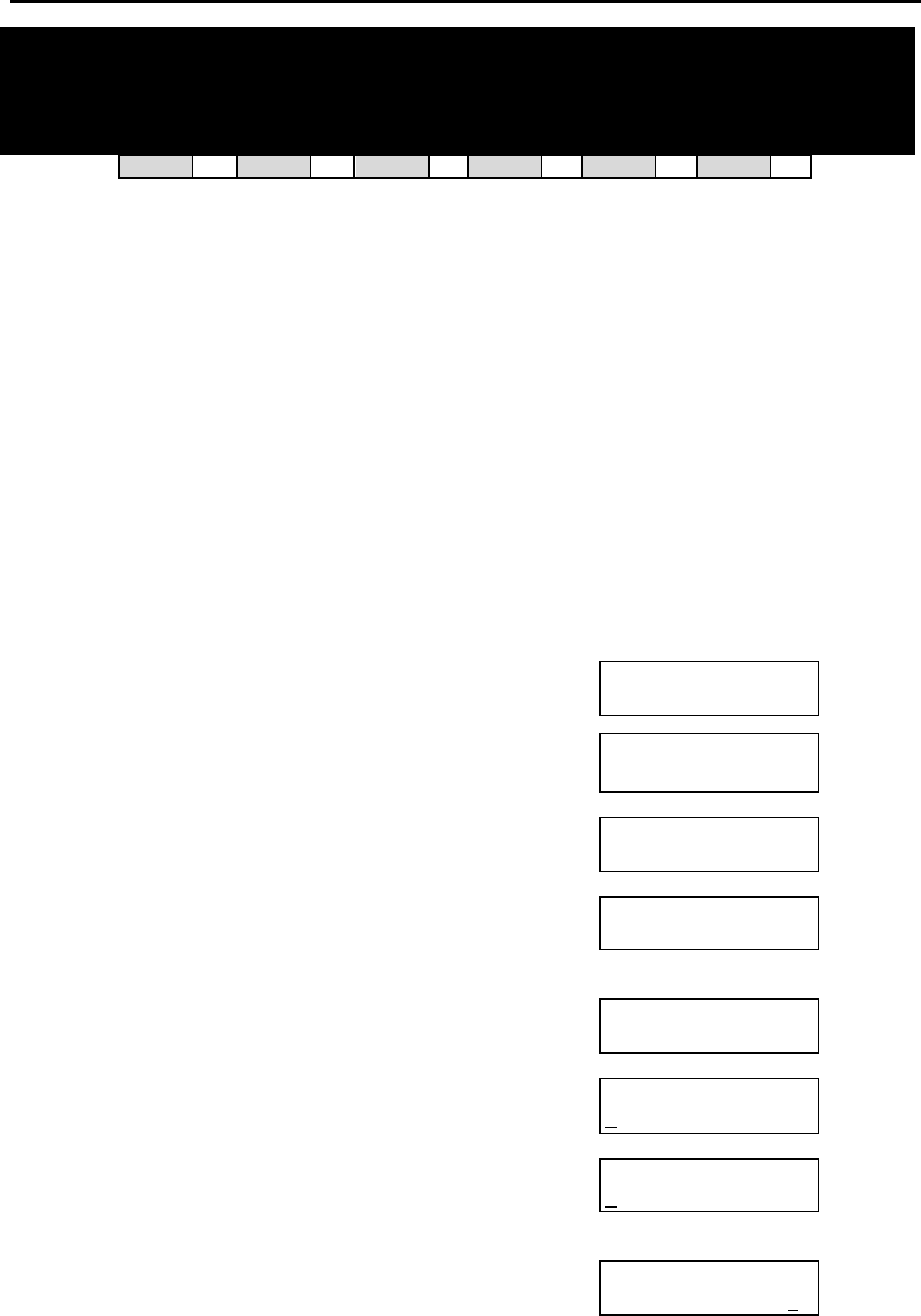
DCS MMC PROGRAMS
COMBINED PROGRAMMING MANUAL NOVEMBER 2001
MMC 800 (Page 1 of 2)
MMC: 800
ENABLE TECHNICIAN
PROGRAM
DCS 33 CI 33 CII 33 816 33 408i 33 408 33
Used to open and close system-level (technician) programming. If programming is not opened
and an attempt is made to access a system MMC, the error message “ACCESS DENIED” will be
displayed.
A four-digit passcode is required to access this MMC (which can be changed in MMC 801).
When opened, this MMC enables access to all MMCs.
The procedure below describes how to open programming.
PROGRAM KEYS
UP & DOWN Used to scroll through options
KEYPAD Used to enter selections
SOFT KEYS Move cursor left and right
SPEAKER Used to store data and advance to next MMC
ACTION DISPLAY
1. Press TRSF 800
Display shows
ENABLE TECH.PROG
PASSCODE:
2. Enter passcode
DCS only – Correct code shows
OR
Compact II, 816 and 408/408i – Correct code
shows
Incorrect code shows (you return to the passcode
entry display so you can try again)
ENABLE TECH.PROG
PASSCODE: ∗∗∗∗
ENABLE TECH.PROG
DISABLE TENANT:1
OR
ENABLE TECH.PROG
DISABLE
ENABLE TECH. PROG
PASSCODE ERROR
3. Enter 1 to enable or enter 0 to disable
OR
Press UP or DOWN to select
DCS only - Press RIGHT soft key to move to tenant
number and enter tenant number (1–2)
ENABLE TECH.PROG
ENABLE TENANT:1
OR
ENABLE TECH.PROG
ENABLE
ENABLE TECH.PROG
ENABLE TENANT:2

DCS MMC PROGRAMS
COMBINED PROGRAMMING MANUAL NOVEMBER 2001
MMC 800 (Page 2 of 2)
4. Press SPEAKER to advance to MMC entry level
801:TEC.PASSCODE
SELECT PROG.ID
5. Enter the MMC required and begin programming.
Follow the instructions for that MMC.
Disabling (Closing) Programming Mode
If you wish to immediately close programming mode when you have finished programming:
§ Return to MMC 800. The display shows that programming is enabled.
§ Use the UP or DOWN key to select DISABLE and press TRSF to exit.
If you do not close programming using MMC 800, programming mode will be automatically disabled
if you do not carry out any programming tasks within the time set in the system timer KMMC LOCK
OUT (see MMC 501, System-Wide Timers).
Default Data: DISABLE (closed)
Passcode=4321
Related Items: None
DCS MMC PROGRAMS
COMBINED PROGRAMMING MANUAL NOVEMBER 2001
MMC 801 (Page 1 of 1)
MMC: 801 CHANGE TECHNICIAN
PASSCODE
DCS 33 CI 33 CII 33 816 33 408i 33 408 33
Used to change the passcode which allows access to MMC 800 (Enable Technician Program)
from its current value.
Note: The passcode is four digits long. The current or “old” passcode is required for this MMC.
PROGRAM KEYS
KEYPAD Used to enter passcodes
SPEAKER Save data and advance to next MMC
ACTION DISPLAY
1. Open programming and select 801 TECH. PASSCODE
NEW CODE:_
2. Enter new passcode
TECH. PASSCODE
NEW CODE:∗∗∗∗
3. Enter new passcode again to verify
TECH. PASSCODE
VERIFY :∗∗∗∗
4. If verification is correct, press RIGHT soft key to con-
tinue and enter desired MMC
TECH. PASSCODE
VERIFY :SUCCESS
If verification is incorrect display shows “Failure”
and system returns to step 2
TECH. PASSCODE
VERIFY :FAILURE
5. Press TRSF to store and exit
OR
Press SPEAKER to advance to MMC
Default Data: Default passcode = 4321
Related Items: MMC 800 Enable Technician Program
DCS MMC PROGRAMS
COMBINED PROGRAMMING MANUAL NOVEMBER 2001
MMC 802 (Page 1 of 1)
MMC: 802 CUSTOMER ACCESS
MMC NUMBER
DCS 33 CI 33 CII 33 816 33 408i 33 408 33
Allows the installer to designate which MMCs the system administrator (customer) has access to.
For example, it is advised that the customer has access to MMC 102, Call Forward, for call for-
warding but it is not advised that the customer has access to MMC 710, LCR Digit Table, for LCR
dial plans. (MMC 802 is for both tenants on DCS systems.)
PROGRAM KEYS
UP & DOWN Used to scroll through options
KEYPAD Used to enter selections
SOFT KEYS Move cursor left and right
SPEAKER Used to store data and advance to next MMC
ACTION DISPLAY
1. Open programming and select 802
Display shows
CUSTOMER ACCESS
100:STN LOCK:YES
DCS only -
Enter desired tenant number (1–2)
OR
Press UP or DOWN key to make selection and
press RIGHT soft key to move cursor
CUSTOMER ACCESS
100:STN LOCK:YES
2. Enter desired MMC number (e.g. 102)
OR
Press UP or DOWN key to make selection and
press RIGHT soft key to move cursor
CUSTOMER ACCESS
102:CALL FWD:YES
3. Enter 1 for YES or 0 for NO
OR
Press UP or DOWN key to make selection and press
LEFT soft key to return to step 3 to make additional en-
tries
CUSTOMER ACCESS
102:CALL FWD:NO
4. Press TRSF to store and exit
OR
Press SPEAKER to store and advance to next MMC
Default Data:
Customers have access to the following MMCs (default = YES):
100–119, 201, 202, 209, 211–14, 216, 300–306, 308, 309, 312, 315, 317, 404–406, 408–410, 412,
414–416, 421, 500, 502, 505, 507, 508, 600–602, 604, 606, 607, 705–708, 714, 715, 720–722, 725,
727, 728.
Related Items: None
DCS MMC PROGRAMS
COMBINED PROGRAMMING MANUAL NOVEMBER 2001
MMC 803 [DCS] (Page 1 of 1)
MMC: 803 ASSIGN TENANT GROUP
DCS 33 CI 77 CII 77 816 77 408i 77 408 77
Allows the assignment of DCS tenant groups on a per-cabinet, slot and port basis. The simple
rule is Cabinet-Slot-Port=Tenant. The simplicity of this program allows for flexible assignments.
The only information needed is the correct correlation of entries.
PROGRAM KEYS
UP & DOWN Used to scroll through options
KEYPAD Used to enter selections
SOFT KEYS Move cursor left and right
SPEAKER Used to store data and advance to next MMC
ACTION DISPLAY
1. Open programming and select 803
Display shows TENANT GROUP
C:1 S:1 P:01 T:1
2. Enter cabinet (C) number (if no change, press RIGHT
soft key to move cursor) TENANT GROUP
C:1 S:1 P:01 T:1
3. Enter slot (S) number (if no change, press RIGHT
soft key to move cursor) TENANT GROUP
C:1 S:1 P:01 T:1
4. Enter port (P) number (if no change, press RIGHT
soft key to move cursor) TENANT GROUP
C:1 S:1 P:01 T:1
5. Enter tenant (T) number (if no change, press RIGHT
soft key to return to step 2) TENANT GROUP
C:1 S:1 P:01 T:1
6. Press TRSF to store and exit
OR
Press SPEAKER to store and advance to next MMC
Default Data: All assignments tenant 1
Related Items: Tenant group
DCS MMC PROGRAMS
COMBINED PROGRAMMING MANUAL NOVEMBER 2001
MMC 804 (Page 1 of 3)
MMC: 804 SYSTEM I/O PARAMETER
DCS 33 CI 33 CII 33 816 33 408i 33 408 33
Provides a means of setting parameters for the system I/O ports to work with one of the follow-
ing:
• a personal computer (PC)
• Station Message Detail Recording (SMDR)
• UCD statistics report/periodic UCD information (except 408/408i)
• CTI (TSAPI) interface (DCS and Compact II only).
All systems have two I/O ports (Ports 1 and 2), except 408/408i which have one I/O port (Port 1).
Programming can be accomplished easily, using the tables below to customise any I/O port.
PARAMETER OPTIONS
Dial 0 Service Type of Service
Dial 1 Baud Rate Speed
Dial 2 Char Length Character Length
Dial 3 Parity Parity Bit
Dial 4 Retry Count Number of Retries
Dial 5 Stop Bit Stop Bit
Dial 6 Wait Time Message Wait Time
Dial 7 DSR Check DSR Check on/off (Compact II, 816 and 408/408i only)
or
SIM Pair No. of the station connected to the Serial Interface Module
(SIM) (DCS only)
SERVICE TYPE
Each port can be set to one of the following service types. Note that the services available depend on
the type of system being programmed. For example, DCS and CII systems provide all the following
services while 408/408i systems provide PC-MMC and SMDR only.
Type Description
PC-MMC PC application
SMDR SMDR report (call logging)
UCD REPT UCD report on request by the
supervisor, or daily
UCD/SMDR Both SMDR and UCD report will
be generated
CTI Dedicated Switch Link Interface
CTI/SMDR CTI and SMDR
CTI/UCD CTI and UCD
CTI/S/U CTI, SMDR and UCD
VM TRACE Voice Mail monitoring
NOT USE Not used
DCS MMC PROGRAMS
COMBINED PROGRAMMING MANUAL NOVEMBER 2001
MMC 804 (Page 2 of 3)
SPEED (BPS)
Dial
DCS/CII/816 408/408i
600 0 N/A
1200 1 2
2400 2 3
4800 3 4
9600 4 5
19200 5 N/A
CHARACTER LENGTH
Dial 7 7 bits
Dial 8 8 bits
PARITY
Dial 0 None
Dial 1 Odd
Dial 2 Even
STOP BIT
Dial 1 1 bit
Dial 2 2 bit
PROGRAM KEYS
UP & DOWN Used to scroll through options
KEYPAD Used to enter selections
SOFT KEYS Move cursor left and right
SPEAKER Used to store data and advance to next MMC
HOLD Used to clear entry (when valid)
ACTION DISPLAY
1. Open programming and select 804
Display shows
SYS I/O PORT (1)
SERVICE:PC-MMC
2. Enter desired port via dial keypad (e.g. 2) (note:
408/408i systems have port 1 only)
OR
Press UP or DOWN key to make selection and press
RIGHT soft key to move cursor
SYS I/O PORT (2)
SERVICE:SMDR
3. Enter parameter option from the above option list via
dial keypad (e.g. 1)
OR
Press UP or DOWN key to make selection and press
RIGHT soft key to move cursor
SYS I/O PORT (2)
BAUD:9600 BPS
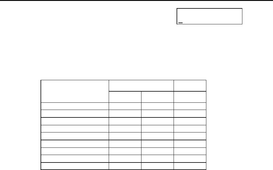
DCS MMC PROGRAMS
COMBINED PROGRAMMING MANUAL NOVEMBER 2001
MMC 804 (Page 3 of 3)
4. Enter desired value via dial keypad (e.g. 19200 baud)
OR
Press UP or DOWN key to display value and press
RIGHT soft key to return to step 2
SYS I/O PORT (2)
BAUD:19200 BPS
5. Press TRSF to store and exit
OR
Press SPEAKER to store and advance to next MMC
Default Data:
DCS/CII/816 408/408i
Option
Port 1 Port 2 Port 1
Service Type PCMMC SMDR SMDR
Baud Rate (bps) 9600 9600 9600
Char Length (bits) 8 8 8
Parity None None None
Retry Count 03 03 03
Stop Bit 1 1 1
Wait Time (msec) 300 300 300
DSR Check Off Off Off
SIM Pair None None N/A
Related Items: PC-MMC programming
SMDR options
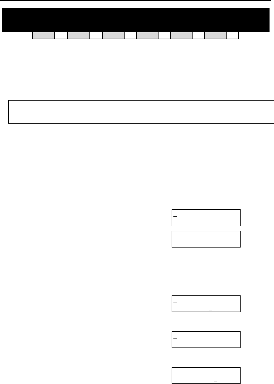
DCS MMC PROGRAMS
COMBINED PROGRAMMING MANUAL NOVEMBER 2001
MMC 805 (Page 1 of 2)
MMC: 805 TX LEVEL AND GAIN
DCS 33 CI 33 CII 33 816 33 408i 33 408 33
Allows the system administrator to set the base level of TX volume and the TSW gain control for
nine time-switch connect types.
There are eight (8) volume levels which are controlled by the UP and DOWN keys on the keyset.
However, there are 11 possible levels in a DCS or Compact II system, nine in an 816 system, and
four in a 408/408i system. With this MMC, you can select the desired levels.
Caution
You should only change TSW gain control values under the supervision of Technical Sup-
port.
PROGRAM KEYS
UP & DOWN Used to scroll through options
KEYPAD Used to enter selections
SOFT KEYS Move cursor left and right
SPEAKER Used to store data and advance to next MMC
HOLD Used to clear previous entry
ANS/RLS Used to select ALL
ACTION DISPLAY
1. Open programming and select 805
Display shows
TX LEVEL CONTROL
LEVEL 0 → 1
2. Press UP or DOWN key to select TX LEVEL CON-
TROL or TSW GAIN CONTROL
OR
Press RIGHT soft key to select
If you selected TX, goto step 3
If you selected TSW, goto step 4
TX LEVEL CONTROL
LEVEL 0 → 1
3. Press RIGHT soft key to go to the volume level
OR
Press UP or DOWN key to go to next volume level
TX LEVEL CONTROL
LEVEL 1 → 2
Enter desired volume level via dial keypad
OR
Use UP or DOWN key to scroll data (00-10)
(Go to step 6 if finished)
TX LEVEL CONTROL
LEVEL 1 → 3
4. Press RIGHT soft key to go to the TSW GAIN CON-
TROL type
OR
Press UP or DOWN key to go to next TSW type
TSW GAIN CONTROL
SLT → SLT:+0.0

DCS MMC PROGRAMS
COMBINED PROGRAMMING MANUAL NOVEMBER 2001
MMC 805 (Page 2 of 2)
5. Press UP or DOWN key to select TSW gain data
Press RIGHT soft key to go back to step 4 or go to
step 6 if finished
TSW GAIN CONTROL
SLT → SLT:+2.0
6. Press TRSF to store and exit
OR
Press SPEAKER to store and advance to next MMC
Default Data:
TX Level: 0 →→ 1, 1 →→ 2, 2 →→ 3, 3 →→4, 4 →→ 5, 5 →→ 6, 6 →→7, 7 →→ 8
TSW Gain: (Only some of the following may apply to your system)
SLTÔÔSLT +0.0
SLTÔÔ ATRK +0.0
SLTÔÔ DTRK +0.0
ATRKÔÔ SLT +0.0
ATRKÔÔ ATRK +1.9
ATRKÔÔ DTRK – 6.0
DTRKÔÔ SLT +1.9
DTRKÔÔ ATRK +1.9
DTRKÔÔ DTRK +0.0
DECTÔÔ SLT +0.0
DECTÔÔ ATRK +0.0
DECTÔÔ DTRK +1.9
SLTÔÔ DECT – 6.0
ATRKÔÔ DECT – 6.0
DTRKÔÔ DECT – 6.0
DECTÔÔ DECT – 6.0
Related Items: None
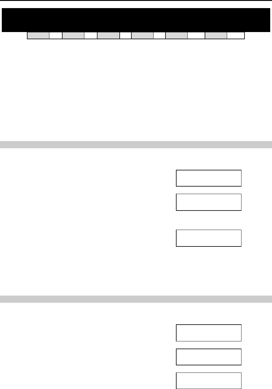
DCS MMC PROGRAMS
COMBINED PROGRAMMING MANUAL NOVEMBER 2001
MMC 806 (Page 1 of 2)
MMC: 806 CARD PRE-INSTALL
DCS 33 CI 33 CII 33 816 33 408i 77 408 77
Allows the pre-programming of a slot for a specific card. For example, after the system is in-
stalled and a new card is added, running this program causes the system to accept the card for
what it is and not for what it is not.
The procedure differs slightly for each type of system, as described below.
PROGRAM KEYS
UP & DOWN Used to scroll through options
KEYPAD Used to enter selections
SOFT KEYS Move cursor left and right
SPEAKER Used to store data and advance to next MMC
n DCS PROCEDURE
ACTION DISPLAY
1. Open programming and select 806
Display shows C1–01 :INSTALL
PRITRK →PRITRK
2. Enter cabinet number (e.g., 3)
OR
Press UP or DOWN key to make selection and press
RIGHT soft key to move cursor
C3–01 :INSTALL
PRITRK →PRITRK
3. Enter slot number (e.g., 5)
OR
Press UP or DOWN key to make selection and press
RIGHT soft key to return to step 2
C3–05 :INSTALL
DLI → DLI
4. Press TRSF to store and exit
OR
Press SPEAKER to store and advance to next MMC
n COMPACT II PROCEDURE
ACTION DISPLAY
1. Open programming and select 806
Display shows O.SLI SLOT
O.2SLI →O.2SLI
2. Press UP or DOWN key to select slot number
EXP.1 SLOT
6DLI →8DLI
3. Press RIGHT soft key to change previous card type
EXP.1 SLOT
8DLI →8DLI
4. Press TRSF to store and exit
OR
Press SPEAKER to store and advance to next MMC

DCS MMC PROGRAMS
COMBINED PROGRAMMING MANUAL NOVEMBER 2001
MMC 806 (Page 2 of 2)
n 816 PROCEDURE
ACTION DISPLAY
1. Open programming and select 806
Display shows EXP. SLOT
NONE →NONE
2. Press RIGHT soft key to change previous card type
EXP. SLOT
NONE →8TRK
3. Press TRSF to store and exit
OR
Press SPEAKER to store and advance to next MMC
Default Data: None
Related Items: None
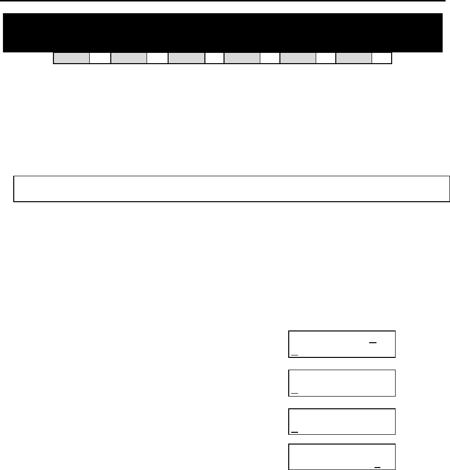
DCS MMC PROGRAMS
COMBINED PROGRAMMING MANUAL NOVEMBER 2001
MMC 807 (Page 1 of 1)
MMC: 807 VOLUME CONTROL
DCS 33 CI 33 CII 33 816 33 408i 33 408 33
Allows the volume levels to be set the for the following keyset features:
KEY TONE NOISE THRES
SIDE TONE ALC THRES
HANDSET TX TX/RX THRES
MIC TX LEVEL TX/RX COMP
NOISE GUARD
Caution
You should only change these values under the supervision of Technical Support.
PROGRAM KEYS
UP & DOWN Used to scroll through options
KEYPAD Used to enter selections
SOFT KEYS Move cursor left and right
SPEAKER Used to store data and advance to next MMC
HOLD Used to clear previous entry
ACTION DISPLAY
1. Open programming and select 807
Display shows VOL.CONTROL:DGP
KEY TONE VOL :1
2. Press RIGHT soft key to move cursor VOL.CONTROL:DGP
KEY TONE VOL :1
3. Press UP or DOWN key to select feature (e.g. SIDE
TONE VOL) and press RIGHT soft key
VOL.CONTROL:DGP
SIDE TONE VOL:1
4. Press UP or DOWN key to select volume and press
LEFT soft key
VOL.CONTROL:DGP
SIDE TONE VOL:2
5. Repeat step 3 to select and change other volume levels
OR
Press TRSF to store and exit
OR
Press SPEAKER to store and advance to next MMC
Default Data:
Key tone vol 1 Noise thres. 1
Sidetone vol 1 Alc thres. 7
Handset tx 3 Tx/rx thres. 3
Mic tx level 3 Tx/rx comp. 5
Noise guard 8
Related Items: None

DCS MMC PROGRAMS
COMBINED PROGRAMMING MANUAL NOVEMBER 2001
MMC 808 (Page 1 of 1)
MMC: 808 T1 TRUNK CODING
Not Used in the UK
DCS MMC PROGRAMS
COMBINED PROGRAMMING MANUAL NOVEMBER 2001
MMC 809 (Page 1 of 1)
MMC: 809 SYSTEM MMC LANGUAGE
DCS 33 CI 77 CII 33 816 33 408i 33 408 33
Allows the assignment of an LCD display based on the system programming language. Your
system supports some or all of the following languages:
ENGLISH DANISH
GERMAN DUTCH
PORTUGAL SPANISH
PROGRAM KEYS
UP & DOWN Used to scroll through options
KEYPAD Used to enter selections
SOFT KEYS Move cursor left and right
SPEAKER Used to store data and advance to next MMC
ACTION DISPLAY
1. Open programming and select 809
Display shows
SYS.MMC LANGUAGE
ENGLISH
2. Press UP or DOWN to make selection and
press RIGHT soft key
SYS.MMC LANGUAGE
DANISH
3. Press TRSF to store and exit
OR
Press SPEAKER to store and advance to next MMC
Default Data: ENGLISH
Related Items: Multi-Language
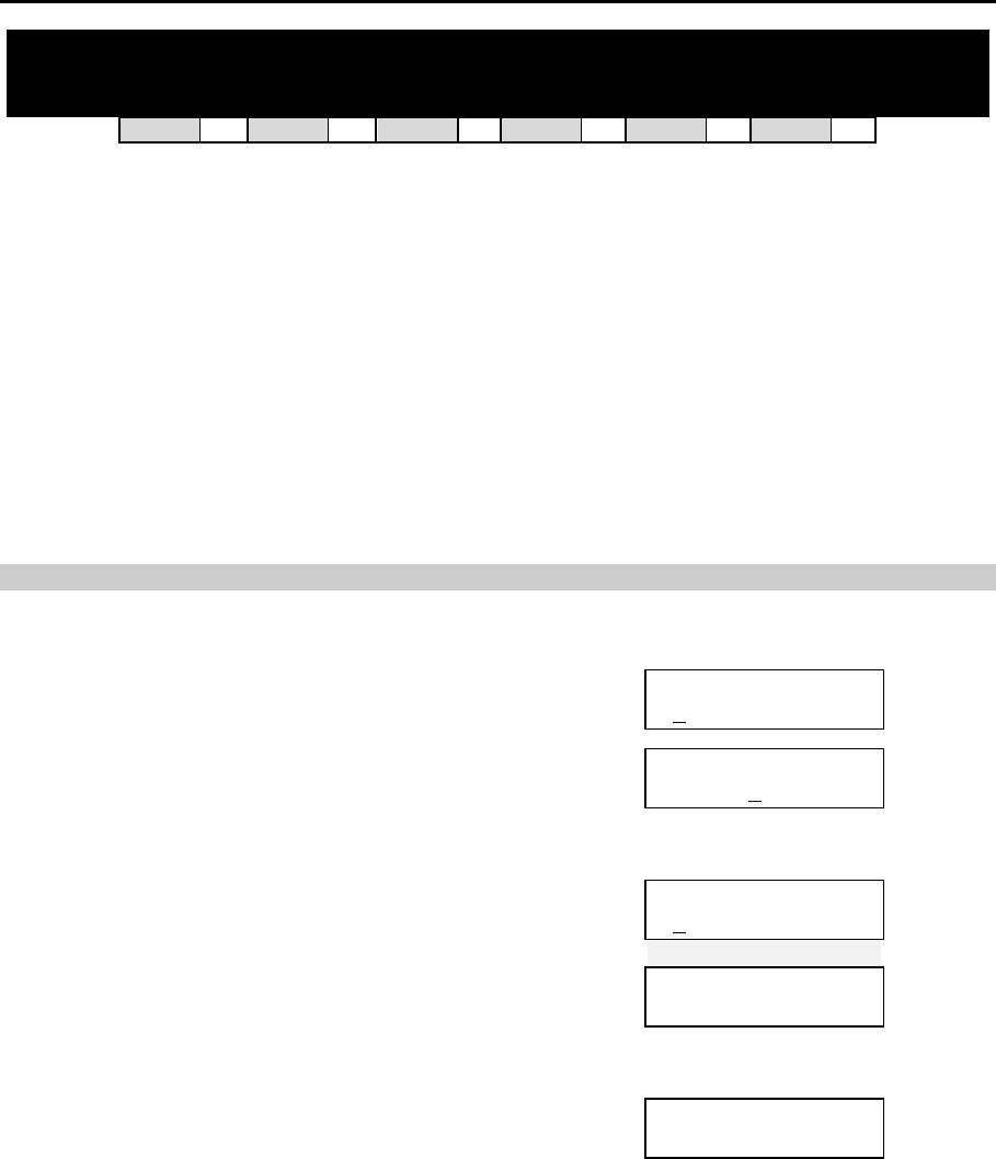
DCS MMC PROGRAMS
COMBINED PROGRAMMING MANUAL NOVEMBER 2001
MMC 810 (Page 1 of 2)
MMC: 810 HALT PROCESSING
DCS 33 CI 33 CII 33 816 33 408i 77 408 77
Used only in the event that all data processing needs to be stopped in either a single cabinet or
slot, or in the entire system. The procedure differs slightly between systems.
Note: You do not need to enable system programming (MMC 800) in order to run this program but you will
still require the technician’s passcode.
PROGRAM KEYS
UP & DOWN Used to scroll through options
KEYPAD Used to enter selections
SOFT KEYS Move cursor left and right
SPEAKER Used to store data and advance to next MMC
ANS/RLS Used to select ALL
n DCS PROCEDURE
ACTION DISPLAY
1. Open programming and select 810
Display shows
HALT/PROCESSING
C:ALL S:ALL→PROC
2a. Enter cabinet selection via dial keypad
OR
Press UP or DOWN key to make selection and press
RIGHT soft key to advance cursor
HALT/PROCESSING
C:3 S:ALL→PROC
2b. Press ANS/RLS to select all cabinets and all slots
HALT/PROCESSING
C:ALL S:ALL→PROC
3. Enter slot number via dial keypad
OR
Press UP or DOWN key to make selection and press
RIGHT soft key to advance cursor
HALT/PROCESSING
C:3 S:5 →PROC
4. Enter 1 for HALT or 0 to PROC
OR
Press UP or DOWN key to make selection and press
RIGHT soft key to enter data and return to step 2
HALT/PROCESSING
C:3 S:5 →HALT
5. Press TRSF to store and exit
OR
Press SPEAKER to store and advance to next MMC
DCS MMC PROGRAMS
COMBINED PROGRAMMING MANUAL NOVEMBER 2001
MMC 810 (Page 2 of 2)
n COMPACT II & 816 PROCEDURE
ACTION DISPLAY
1. Open programming and select 810
Display shows
HALT/PROCESSING
SLOT NO:ALL→PROC
2. Enter slot number via dial keypad (e.g. 5)
OR
Press UP or DOWN key to make selection and press
RIGHT soft key to advance cursor
OR
HALT/PROCESSING
SLOT NO:5 →PROC
Press ANS/RLS to select all slots
HALT/PROCESSING
SLOT NO:ALL→PROC
3. Enter 1 for HALT or 0 to PROC
OR
Press UP or DOWN key to make selection and press
RIGHT soft key to enter data and return to step 2
HALT/PROCESSING
SLOT NO:5 →HALT
4. Press TRSF to store and exit
OR
Press SPEAKER to store and advance to next MMC
Default Data: None
Related Items: None
DCS MMC PROGRAMS
COMBINED PROGRAMMING MANUAL NOVEMBER 2001
MMC 811 (Page 1 of 1)
MMC: 811 RESET SYSTEM
DCS 33 CI 33 CII 33 816 33 408i 33 408 33
Provides two methods of restarting the system. The first method (CLEAR MEMORY) restarts the
system and clears all memory. The second method (RESET SYSTEM) restarts the system only. If
CLEAR MEMORY is selected, system data will return to default values.
Note: You do not need to enable system programming (MMC 800) in order to run this program but you will
still require the technician’s passcode.
WARNING: Extreme care should be taken when using this MMC
If the system is restarted, all voice/data connections are dropped.
If memory is cleared, all customer data is deleted and the system
returns to default status.
PROGRAM KEYS
UP & DOWN Used to scroll through options
KEYPAD Used to enter selections
SOFT KEYS Move cursor left and right
ACTION DISPLAY
1. Open programming and select 811
Display shows
SYSTEM RESTART
RESET SYSTEM?NO
2. Press UP or DOWN key to make selection
(RESET SYSTEM or CLEAR MEMORY)
After selection is made, press RIGHT soft key to move
cursor to YES/NO option
SYSTEM RESTART
CLEAR MEMORY?NO
3. Press UP or DOWN key to make selection and press
RIGHT soft key
SYSTEM RESTART
CLEAR MEMORY?YES
4. Press UP or DOWN key to make selection and press
RIGHT soft key
Warning: Selecting CLEAR MEMORY will erase all
data in the system and return default values
SYSTEM RESTART
ARE YOU SURE?YES
If RESET SYSTEM is selected, system will return to nor-
mal programmed status
Default Data: None
Related Items: None
DCS MMC PROGRAMS
COMBINED PROGRAMMING MANUAL NOVEMBER 2001
MMC 812 (Page 1 of 1)
MMC: 812 SELECT COUNTRY
DCS 33 CI 77 CII 33 816 33 408i 33 408 33
IMPORTANT
This MMC should be run before any other programming is done to ensure
that the correct software for your country has been selected, or to change
the selection if required.
When using this MMC, the system is restarted to make the selection effective.
Note: You do not need to enable system programming (MMC 800) in order to run this program but you will
still require the technician’s passcode.
PROGRAM KEYS
UP & DOWN Used to scroll through options
KEYPAD Used to enter selections
SOFT KEYS Move cursor left and right
ACTION DISPLAY
1. Open programming and select 812
Display shows the country selected by the installer
(e.g. UK).
To accept this setting, go to step 4.
SELECT COUNTRY
UK
2. Press UP or DOWN key to select a different country
and press RIGHT soft key
SELECT COUNTRY
DENMARK
3. Press UP or DOWN key to select YES or NO and press
RIGHT soft key
Warning: if you select YES, this will clear the
memory and restart the system
DEFAULTING SYSTM
ARE YOU SURE?YES
4. Press TRSF to store and exit
OR
Press SPEAKER to store and advance to next MMC
Default Data: NONE
Related Items: All MMCs

Samsung Telecoms (U.K.) Limited
Brookside Business Park, Greengate, Middleton, Manchester M24 1GS
Tel: 0161 655 1100 Fax: 0161 655 1166
