Samsung Shr 1040K Users Manual
SHR-1040K to the manual 6e17d115-65c6-4971-a3cf-40d032e3a084
2015-01-23
: Samsung Samsung-Shr-1040K-Users-Manual-278324 samsung-shr-1040k-users-manual-278324 samsung pdf
Open the PDF directly: View PDF ![]() .
.
Page Count: 68

DIGITAL VIDEO RECORDER
SHR-1040/SHR-1040K User’s Manual
English Français Spanish
SHR-1040/SHR-1040K-ENG 2006.4.4 11:12 AM ˘`i

English
SHR-1040/1040K USER’S MANUAL
ii
Please be sure to keep the following in mind for the right use of the product to
pre-vent proprietary risk or damage.
■Do not use multiple plugs at once.
●This may cause abnormal heat generation or fire
■Do not put a vase, flowerpot, cup, cosmetics, medicine, or vessel
with water around you.
●This may cause fire.
■Do not bend the power cord forcibly nor put a heavy material on it.
●This may cause fire.
■Do not touch the power plug with wet hands.
●This may cause electric shock.
■Insert the power plug firmly enough not to shake.
●This imperfect connection may cause fire.
■Keep the product off humidity, dust, or soot.
●This may cause fire or electric shock.
■Do not put metals(coin, hair pin, metal piece, etc.) or inflammable
materials(match, paper, etc.) in the ventilation hole.
●This may cause fire.
■Keep the surrounding temperature between 32˚F to 104˚F and keep
the product off humidity.
●This may cause breakdown.
■Secure sufficient ventilation.
●This may cause abnormal operation due to high temperature.
■Keep the product off direct ray of light or heat from the heating
device
●This may cause fire.
■Do not disassemble, repair, or remodel the product.
●This may cause fire, electric shock, or injury due to abnormal operation.
■Do not pull out the power cord.
●This may destroy the power cord, eventually, cause fire or
electric shock.
■Plug out in the event of thunder or lightning.
●This may cause fire.
■Keep your children off the battery after you take it out of the product.
They tend to swallow it unconsciously.
●If your children swallow it, please see the doctor immediately.
■Install the product at a safe place or attach the product to the wall or
ceiling with a stand firmly enough not to fall to the ground.
●This may injure people.
Safety Regulations
SHR-1040/SHR-1040K-ENG 2006.4.4 11:12 AM ˘`ii

English
iii
WARNING
[Battery]
As wrong exchange of the battery in SHR-1040 may cause explosion, you shall use
the certified battery for SHR-1040.
The battery specification is as follows.
-Normal Voltage : 3V
-Normal Capacity : 220mAh
-Continuous Standard Load : 0.2mA
-Operating Temperature : -22˚F ~ +140˚F
Before we start
Standards Approvals
Note :
This equipment has been tested and found to comply with the limits for a Class
A digital device, pursuant to part 15 of the FCC Rules. These limits are designed
to provide reasonable protection against harmful interference when the equip-
ment is operated in a commercial environment.
This equipment generates, uses, and can radiate radio frequency energy and, if
not installed and used in accordance whit the instruction manual, may cause
harmful interference to radio communications. Operation of this equipment in a
residential area is likely to cause harmful interference in which case the user
will be required to correct the interference at his own expense.
This User’s Manual describes the basic usage of SHR-1040.
This Manual contains all the matters necessary for using SHR-1040 such as brief
instruction, part name, function, connecting other equipment, and menu setup of
SHR-1040.
- SEC retains the copyright on this User’s Manual.
- This User’s Manual cannot be copied without SEC’s prior written approval.
- We are not liable for any or all losses to the product incurred by your use of
non-standard product or violation of User’s Manual.
- If you want to open the system case to touch the inside, please consult with an
expert who works for the shop where you bought the product.
- You may download open source codes from the following website.
(See CCTV Part of http://www.sec.co.kr)
SHR-1040/SHR-1040K-ENG 2006.4.4 11:12 AM ˘`iii

English
iv
Safety Regulations
Before we start
Standards Approvals
Chapter 1. Overview
1. Introduction
2. Features
3. Part Names and Functions
4. Remote Controller
Chapter 2. Installation
1. Installation Environment Setup
2. Checking Product & Accessory
3. HDD Addtion
Chapter 3. DIY Carmera
1. Standard Camera
2. Nightvision Camera
Chapter 4. Connecting with Other device
1. Connecting the Video, Audio, and Monitor
2. Connecting the Alarm Input/Output
Chapter 5. Basic Operation
1. System Operation
2. Live Screen Mode
3. Key Functions
3.1. Channel Key & Mode Key
3.2. Pip Key
3.3. Zoom Key
3.4. Freeze Key
3.5. Sequence Key
3.6. Alarm Key
Contents
1
iii
ii
1-1
1-2
1-3
1-6
2
2-1
2-2
2-3
3
3-1
3-5
4
4-1
4-2
5
5-1
5-2
5-3
5-3
5-3
5-4
5-4
5-5
5-5
SHR-1040/SHR-1040K-ENG 2006.4.4 11:12 AM ˘`iv

English
v
Chapter 6. Menu Setup
1. Main Setup Menu
2. Clock/Display Setup
3. Record Mode Setup
4. Title Setup
5. Dwell Time Setup
6. Alarm Setup
7. Event Record Mode Setup
8. Timer Record Setup
9. System Setup
10. System Information
Chapter 7. Recording
1. Basic Recording
2. Timer Recording
3. Motion Recording
4. Alarm Recording
5. Stop Recording
Chapter 8. Search & Playback
1. Search Menu
2. Date Time Search
3. Record Event Search
4. Alarm Event Search
5. Loss Event List
6. Power Event List
7. Basic Playback
Chapter 9. Appendix
1. Product Specification
2. Recommended HDD List
3 .Outline Drawing
6
7
8
9
6-1
6-2
6-3
6-4
6-5
6-6
6-7
6-9
6-10
6-14
7-1
7-1
7-2
7-2
7-3
8-1
8-2
8-2
8-3
8-3
8-4
8-4
9-1
9-4
9-5
SHR-1040/SHR-1040K-ENG 2006.4.4 11:12 AM ˘`v

Chapter 1. Overview
English
1
SHR-1040/SHR-1040K-ENG 2006.4.4 11:12 AM ˘`1

SHR-1040/1040K USER’S MANUAL
1-1
English
1
Introduction
The SHR-1040 digital video recorder is a digital video recorder that records and plays back
video and audio input from four cameras. It records and plays back each channel of video data
in MPEG4 format, and audio data in installed HDD format, by using the G-723 compression
standard.
●DVR is a digital device that stores video and audio data by using a hard disk drive, unlike a
video cassette recorder using video tapes. DVR enables users to easily play back and
search stored data, and edit and send data which are stored in digital signal format.
Users can compress, store and send moving images, and search listings on an hourly or
daily, camera unit and event basis by using this DVR with standard video and data com-
pression technology.
SHR-1040/1040K USER’S MANUAL
1-1
English
SHR-1040/SHR-1040K-ENG 2006.4.4 11:12 AM ˘ ` 1-1

1-2
English
■Adjusts recorded data in three steps.
- HIGH, NORMAL, LOW
■Adjusts the number of record fields per second.
- NTSC : 1~ MAX 30 IPS
■Records before-event (Alarm or Motion) data based on pre-set hours. (Pre-Alarm)
- 0 ~ 5SEC
■Audio-records and plays back selected channels.
■Offers a timer used for time record.
■Records video and audio with alarm.
■Offers various playback speeds.
■Offers easy-to-use search functions.
- Date & Time Search, Event(Record, Alarm, Motion, Timer) Search
■Instantly pauses the current screen. (FREEZE)
■Offers 2X Zoom for video images monitored or played back by the user.
■Offers a variety of screen split modes.
- Full Screen Display, 4 Split Display, Sequence Display, PIP Display
■Allows the user to enjoy audio and video over a PC monitor through VGA Out.
2
Features
SHR-1040/SHR-1040K-ENG 2006.4.4 11:12 AM ˘ ` 1-2
SHR-1040/1040K USER’S MANUAL
1-3
English
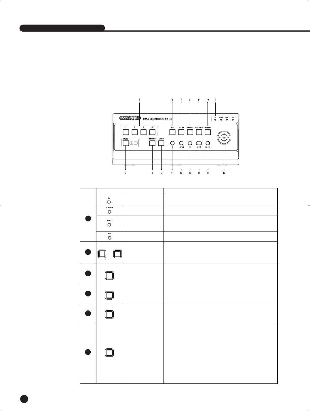
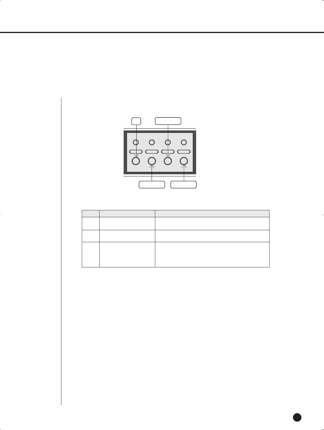
No. Name Function
SHR-1040/1040K USER’S MANUAL
Power LED
HDD LED Displays Normal Access to HDD. Upon Access to HDD, LED
repeats on and off.
Displays power On/Off condition.
1
2
3
5
Alarm LED lights on when an event occurs.
Rec LED Displays the record condition.
...
1 4
MODE
SEARCH
MENU
PIP
6
4
CH1, CH2,
CH3, CH4
The screen is switched to Single Mode when each channel
key is pressed during live programming, and the screen of
the channel is displayed in Full Screen.
During initial booting, the screen is displayed in four split.
When the Mode Key is pressed, the screen is switched to
single or split screen.
Enters the date/time of video and audio signals recorded in HDD,
select events from the RECORD and ALARM EVENT SEARCH,
and views the POWER EVENT LIST and LOSS EVENT LIST.
Displays the MAIN MENU, and exits the MENU Screen by
pressing the button again.
Enters the PIP Mode when the PIP Button is pressed in the
Single Screen. There must be two or more input channels.
(1) PIP is enabled when the sequence of the Single Screen
(Main Screen) is turned off.
(2) The Main Screen moves to Channel 1, 2, 3 and 4 in
sequence when the up/down or left/right button is pressed.
(3) Main-Sub switching: The screen is switched when the Enter
Button is pressed in the PIP Screen while the Sequence is
turned off.
Screen Split
Selection Button
SEARCH
MENU
PIP
[SHR-1040]
3
Part Names & Function
SHR-1040/SHR-1040K-ENG 2006.4.4 11:12 AM ˘ ` 1-3
1-4
English
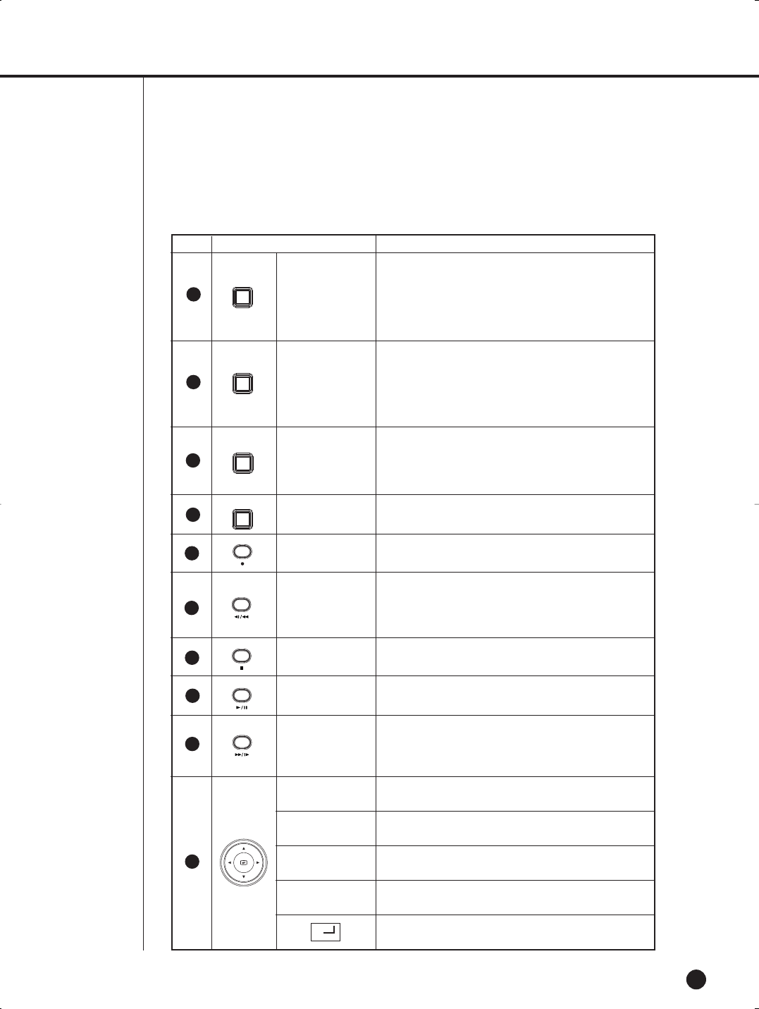
No. Name Function
RECORD
ALARM
ZOOM
SEQUENCE
FREEZE
You can view X2 screen by pressing the ZOOM Button in
the single screen.
When you press the up/down and the left/right key in the
Zoom screen, the selected Zoom Area moves. Press the
Enter button to view X2 Zoom Screen of the selected area.
Press the Freeze Button to freeze the current displayed
screen, and press the Freeze Button again to cancel the
Freeze.
The Freeze marker is displayed on top of the screen in
Freeze Mode.
In Normal Record Mode, video signals are recorded.
When pressing the Sequence Button in the Single Screen,
the screen is switched to each channel with video In.
When the Alarm Button is selected, the Alarm is canceled.
8
9
10
11
12
13
14
15
16
FREEZE
SEQUENCE
ALARM
ZOOM
➛
❿
❷
➛
Fast/Step
Reverse
STOP
PLAY/PAUSE
Fast/Step
Forward
7
Fast Reverse: Used for fast search in reverse direction
playback.
Step Reverse: Used for cut-by-cut search in reverse
direction during pause.
Ends search during playback and recording.
Operates in toggle for play/pause during playback.
Fast Forward: Used for fast search in forward direction
during playback.
Step Forward: Used for cut-by-cut search in forward
direction during pause.
Direction key used to set the details of the Menu.
Used to increase the value of setting, or direction key used
to set the details of the Menu.
Direction key used to set the details of the Menu.
Used to decrease the value of setting, or direction key used
to set the details of the Menu.
Plays the role of Enter Key when setting the Menu.
SHR-1040/SHR-1040K-ENG 2006.4.4 11:12 AM ˘ ` 1-4
SHR-1040/1040K USER’S MANUAL
1-5
English
Caution
Caution
The ventilation outlet may be blocked. Do not operate the DVR on a carpet or other soft surfaces.
When you operate the DVR in a cabinet or on a rack, check whether a ventilation device is properly installed.
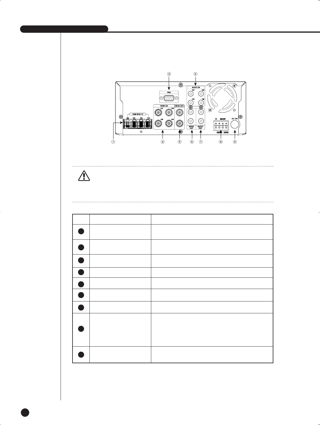
No. Name Function
Connector linked to the Port DIY CAMERA.
Composite video signal input connector (BNC Style
Connector)
Composite video signal output connector (BNC Style
Connector)
VGA video signal output connector
Audio signal input connector (RCA Jack)
Video signal output connector (RCA Jack)
Audio signal output connector (RCA Jack)
- ALARM IN: Alarm input connector. Receives alarm signals
from outside.
- ALARM OUT: Alarm output connector. Sends alarm signals to
external devices.
- ALARM RESET: Alarm reset connector
Supports 12V power socket.
CAM IN RJ-11
BNC VIDEO IN
BNC VIDEO OUT
VGA
AUDIO IN
RCA VIDEO OUT
RCA AUDIO OUT
ALARM
DC IN
5
6
7
8
9
1
2
3
4
[SHR-1040]
SHR-1040/SHR-1040K-ENG 2006.4.4 11:12 AM ˘ ` 1-5
1-6
English
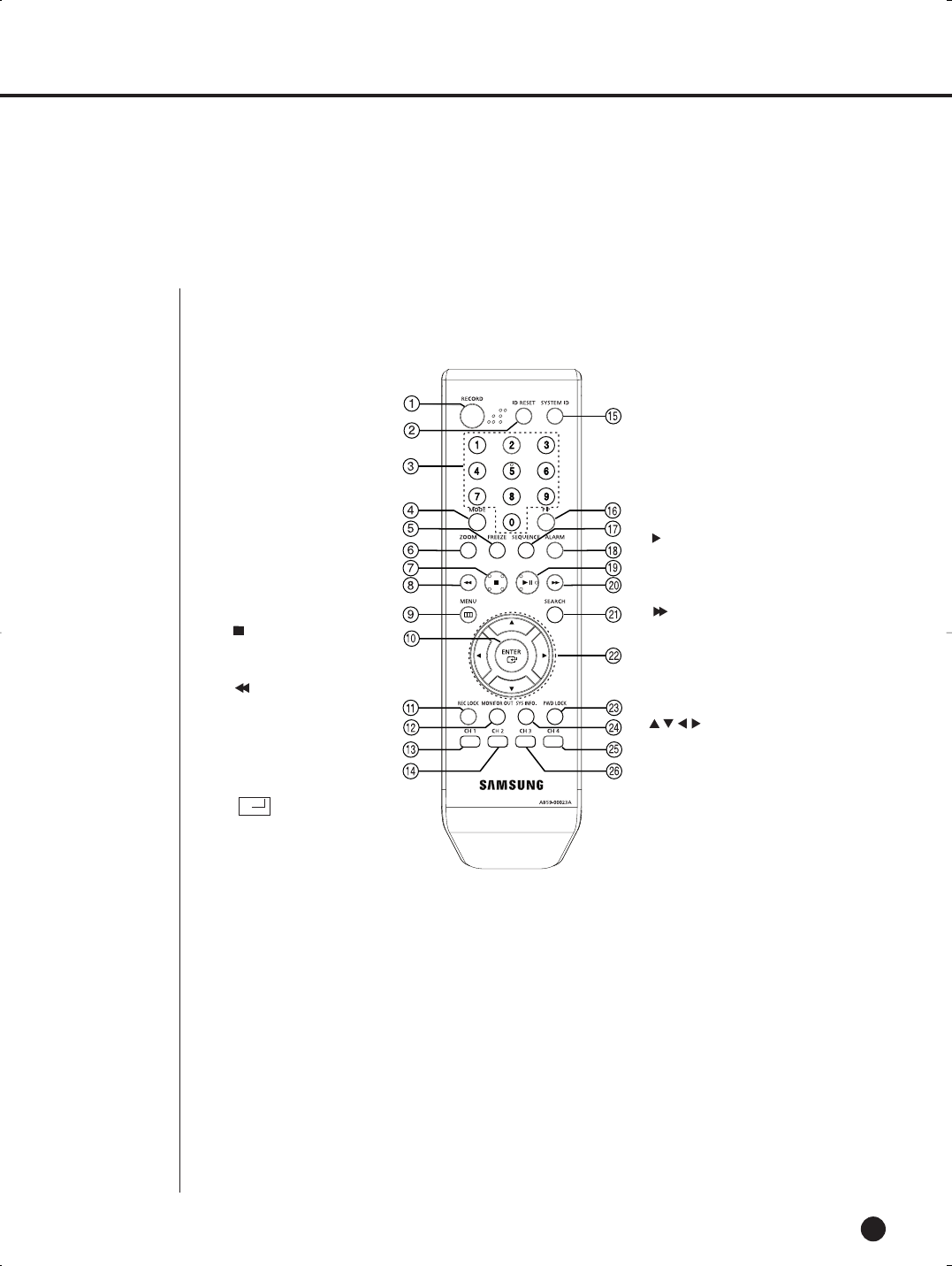
1. RECORD
Starts the recording as the setup
record setting in normal record
mode.
2. ID RESET
The ID is reset.
3. NUMBER KEY
Press to select one of single
channels in Live mode. Use this
for typing purposes in a numeric
input mode.
4. MODE
Selects split-screen.
5. FREEZE
Runs the FREEZE function in live
mode.
6. ZOOM
Press to enlarge the single chan-
nel picture to its double.
7. (STOP)
Ends search during playback and
recording.
8. FR (fast reverse) : used for quick
backwardsearch while in play.
9. MENU
Either goes to the system menu
screen or moves to the upper
menu from the lower menu.
10. (ENTER)
Shows the cursor for the
channel selection in live mode or
used as the select button for
menu setup.
11. REC LOCK
You can check if REC LOCK is set to
ON/OFF.
12 . MONITOR OUT
You can check which mode is set for
the current monitor output.
13. CH 1
Displays SINGLE CH 1.
14. CH 2
Displays SINGLE CH 2.
15. SYSTEM ID
Confirms system and remote
control ID and changes the
remote control ID.
16. PIP
In Single mode, press to watch
another channel in a sub picture.
17. SEQUNCE
The single channel mode switch-
es according to the specified time
on the menu.
18. ALARM
Cancels the alarm while the
alarm is going off.
19. II
Play/Pause : pauses and
resumes the search screen
while in play.
20 .FF (fast forward) : used for
quick forward search while in
play.
21. SEARCH
Searches for data on the HDD.
22.
Used for changing settings
or for moving the cur-sor
up/down/left/right in live
mode and on the menu and
search screens.
23. PWD LOCK
You can check if the password lock
(PWD LOCK) is set to ON/OFF.
24. SYS INFO.
You can check out information on the
system version.
25. CH 3
Displays SINGLE CH 3.
26. CH 4
Displays SINGLE CH 4.
4
Remote Controller
➛
To change the remote control ID
While pressing the SYS ID key, enter the numeric ID in two digits (Default ID: 00).
ex) If you want to change the remote control ID to “08”: While pressing the SYS ID key, enter 0 and 8 and press it again to check if the ID is
changed to 08.
SHR-1040/SHR-1040K-ENG 2006.4.4 11:12 AM ˘ ` 1-6

Chapter 2. Installation
2
English
SHR-1040/SHR-1040K-ENG 2006.4.4 11:12 AM ˘ ` 1-8

SHR-1040/1040K USER’S MANUAL
2-1
English
1
Installation Environment Setup
Do not play DVR on the carpet or other soft material to prevent clogging of the air ventilator.
To play DVR on the cabinet or rack, be sure to check the ventilation condition.
You should pay attention to the following before you use the product.
1. Do not use it outdoor.
2. Do not let water or liquid in the connection part or the product itself.
3. Do not impose excessive shock or force.
4. Do not pull out the power plug unreasonably.
5. Do not disassemble the product on your own.
6. Do not exceed the rated input or output range.
7. Use certified power cord only.
8. Use the power cord with a ground for the product with an input ground.
SHR-1040/1040K USER’S MANUAL
SHR-1040/SHR-1040K-ENG 2006.4.4 11:12 AM ˘ ` 2-1
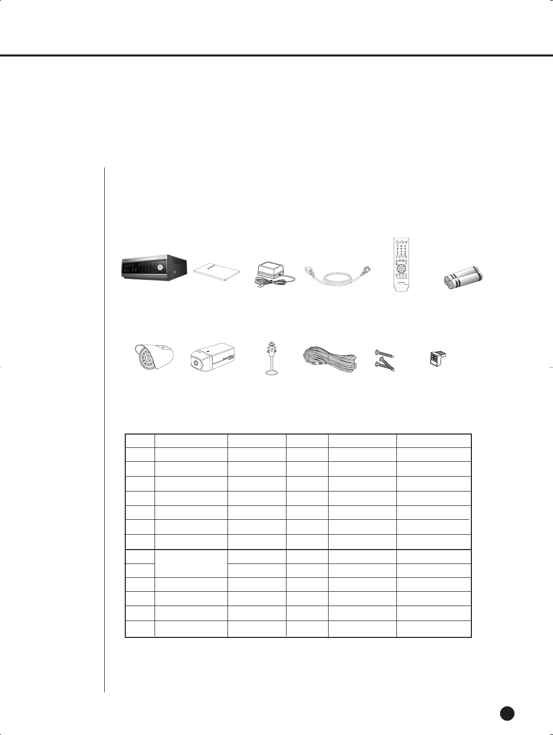
NO Item Model Q’ty SHR-1040/XAA SHR-1040K/XAA
1 DVR SHR-1040 1 o o
2 User’s Manual - 1 o o
3 Warranty Card - 1 o o
4 Adapter ADP-5412WD 1 o o
5 Power Cord - 1 o o
6 Remote Controller - 1 o o
7 Battery Alkaline - 2 o o
8 SOC-N120 2 x o
9 SOC-C120 2 x o
10 Camera Bracket SBR-110S 4 x o
11 Camera Cable MCB-60 4 x o
12 Screw - 12 x o
13 Sensor Connector - 4 x o
2-2
EnglishEnglishEnglish
Upon delivery of a product, you shall unwrap the product and put it on the even floor or where
you want to use it. Then you shall check if the following items are in it.
Adapter
(AB44-00015A) Remote Controller
(AB59-00023A)
User’s Manual
(B68-00592A)
Power Cord
(AB39-10601F)
Battery Alkaline
(AB39-10601F)
SHR-1040
SOC-N120
2
Checking Product & Accessory
Camera Bracket Camera Cable Screw Sensor ConnectorSOC-C120
SHR-1040/XAA : No.1 ~ No.7 items are only included.
WARNING) SHR-1040 set must use the adapter we provide.
CAMERA
SHR-1040/SHR-1040K-ENG 2006.4.4 11:12 AM ˘ ` 2-2
SHR-1040/1040K USER’S MANUAL
2-3
English
3
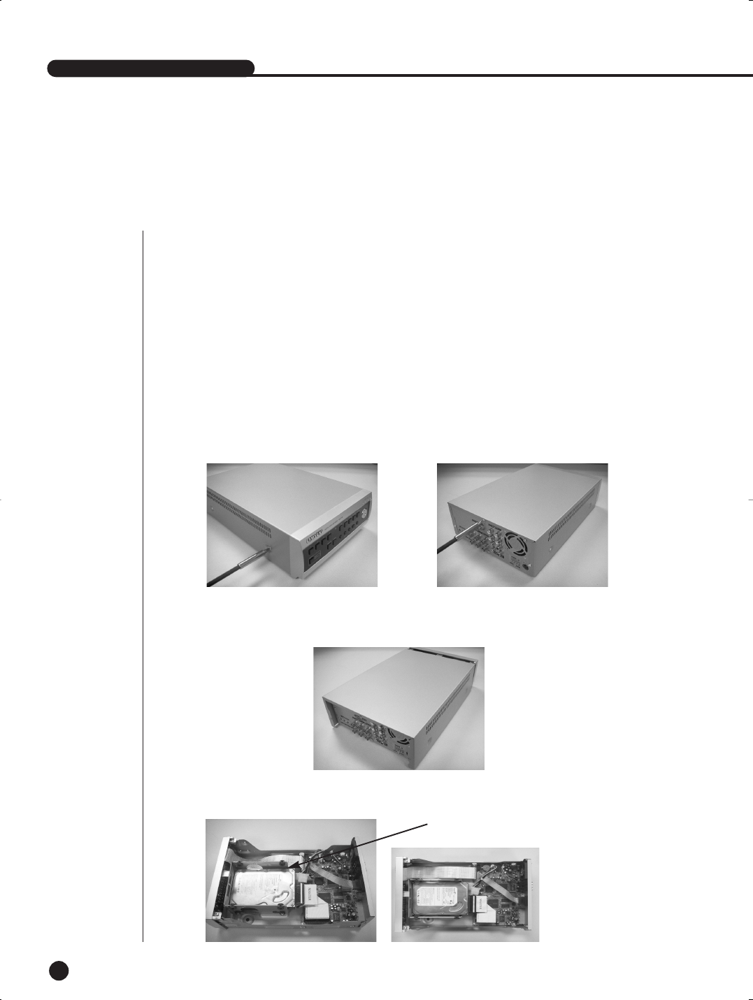
HDD Addtion
You can install one additional hard disk drive inside the product (Max. 2 HDDs). However, there are lots of factors inside that
may cause electrical shock, physical damage or malfunction. So please follow the instructions below to mount the HDD as
the product couldn’ t recognize the additionally installed HDD or may not work properly due to incorrect installation or connec-
tion.
[Installation Instructions]
• Make sure that any cable should NOT be stuck between components inside and do NOT use an uninsulated cable of which
coating is stripped off (Otherwise, it can cause fire or malfunction).
• Any sharp edges inside the product can cause a physical damage during the installation.
• Keep the screws or components removed for HDD addition in a place where you can easily locate them when necessary.
Uninstalled screws or components can cause malfunction or inoperability.
[To install an additional HDD]
1. Loosen the screws, two on each side (left/right) and three on the rear, to remove the cover.
2. Remove the cover.
(Push the cover back before lifting up on the rear side)
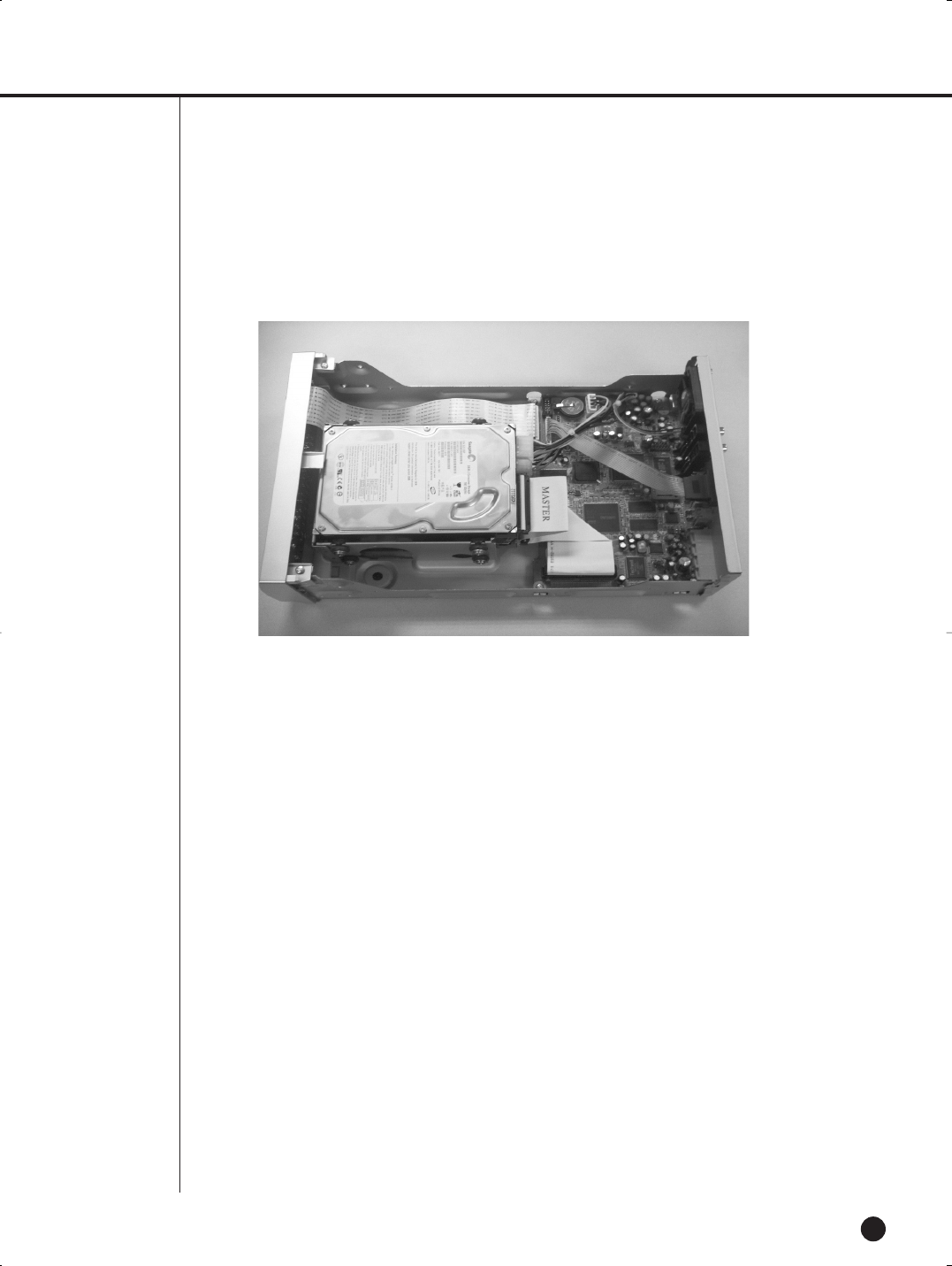
3. There is a bracket (BRACKET-HDD) inside for mounting and fixing the HDD.
BRACKET-HDD
SHR-1040/SHR-1040K-ENG 2006.4.4 11:12 AM ˘ ` 2-3
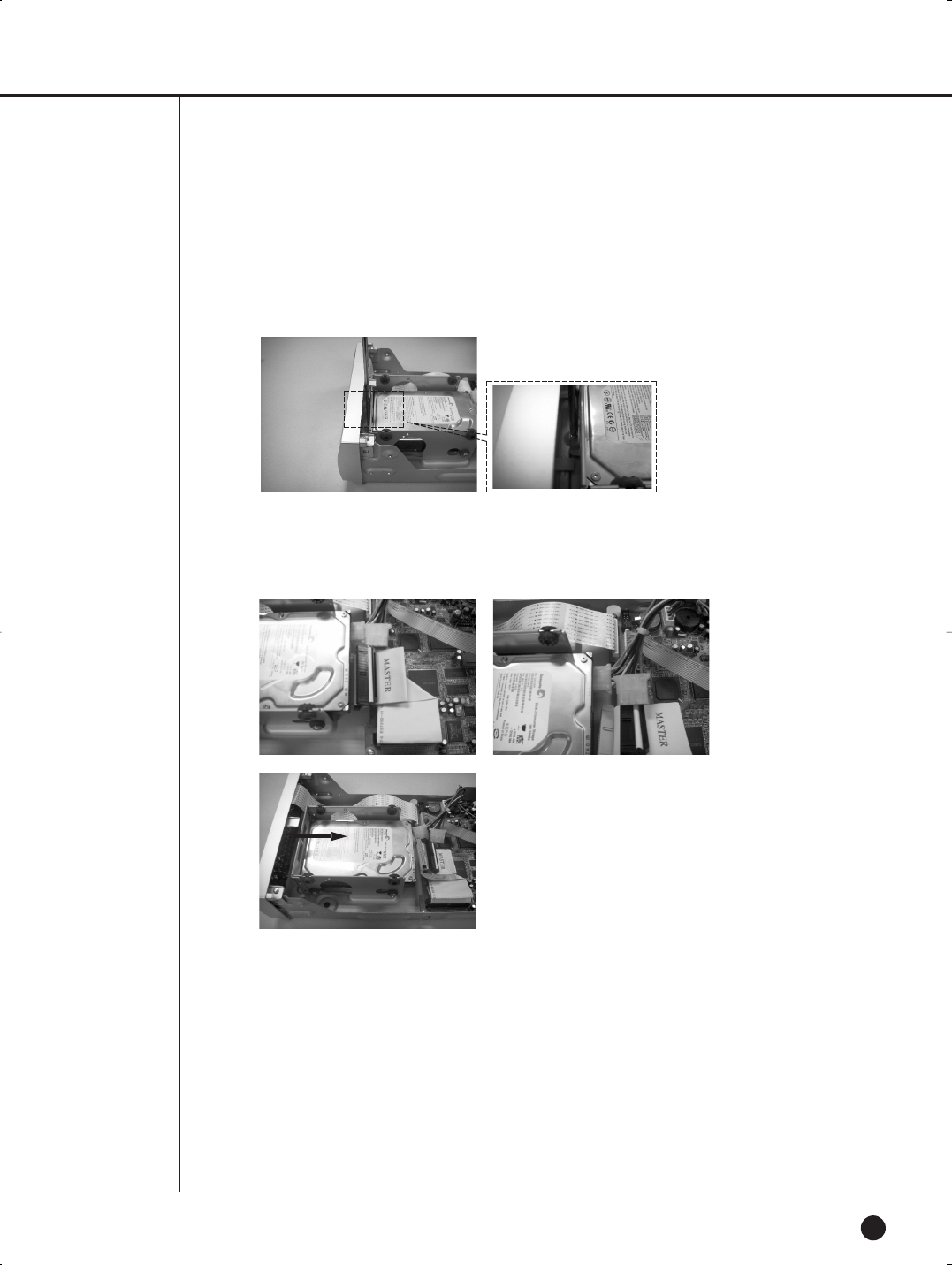
2-4
English
5. Disconnect the power supply cable and the signal cable (IDE cable) from the current HDD. Push the
bracket to the arrow direction as in the picture below and lift it up from the bottom.
6. Use the four screws provided (SCREW-SPECIAL: PWH,+,-,6-32UNC,L14.7(4.2),ZPC) to fix the old HDD
and the additional with the bracket
(Make sure you fasten the screws firmly so that they are not loose from vibration).
SHR-1040/SHR-1040K-ENG 2006.4.4 11:12 AM ˘ ` 2-4
SHR-1040/1040K USER’S MANUAL
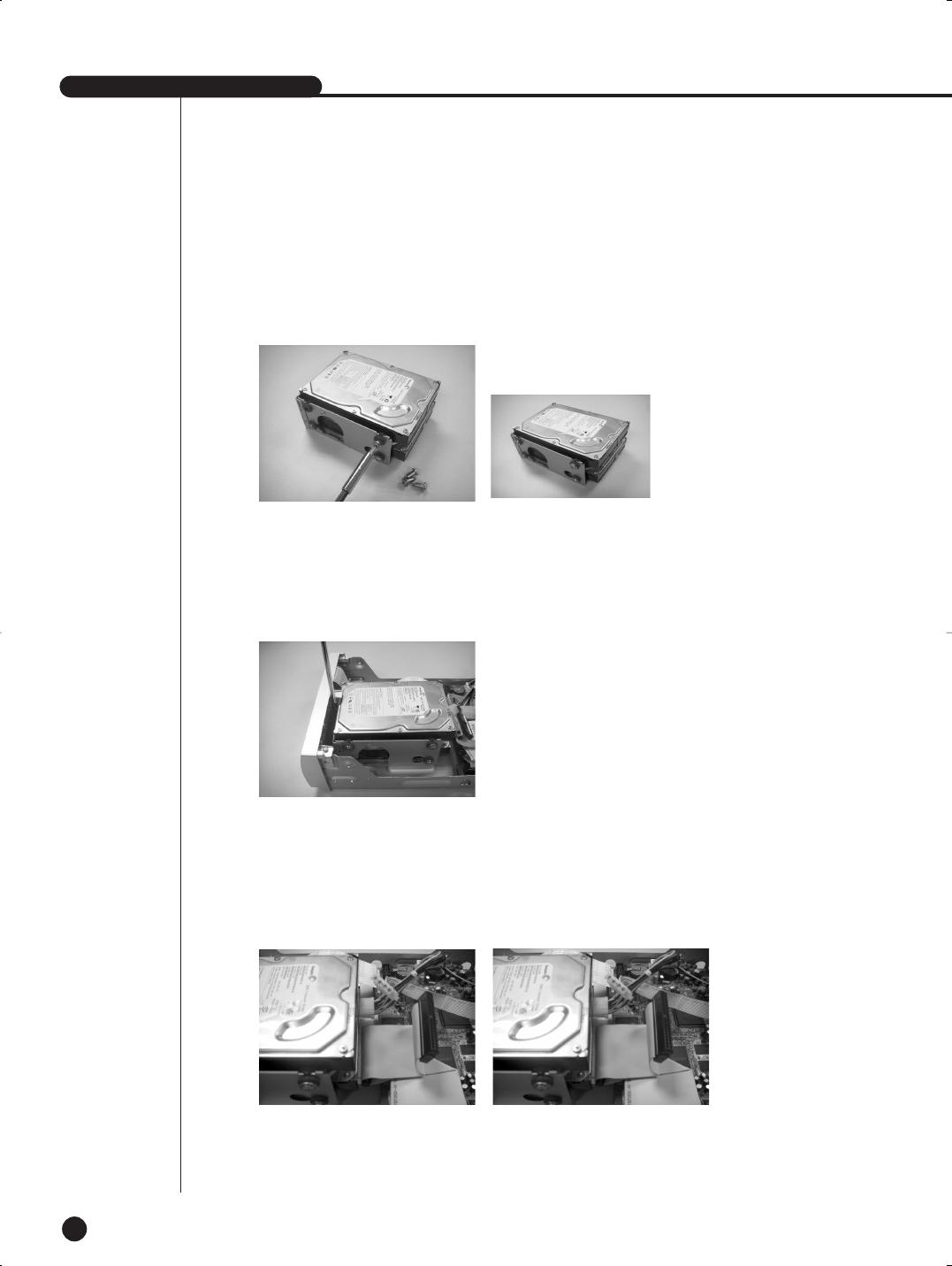
2-5
English
7. Mount the HDD-fixed bracket to its original position. (Installation is done in the reverse order of the disas-
sembly. Fit the bracket (BRACKET-HDD) into the bottom hole and fix the screw).
8. When done (make sure the bracket is firmly fixed), connect the power supply cable and the signal cable
(IDE) to both the old and the additional HDD (see the picture below).
9. Check if all the connections (connectors) are properly made and firmly fixed, and close the cover.
SHR-1040/SHR-1040K-ENG 2006.4.4 11:12 AM ˘ ` 2-5
2-6
EnglishEnglishEnglish
10. Use the screws (two for each side and one for the rear) in step 1 above to fix the cover.
SHR-1040/SHR-1040K-ENG 2006.4.4 11:12 AM ˘ ` 2-6

SHR-1040/SHR-1040K-ENG 2006.4.4 11:12 AM ˘ ` 2-7

Chapter 3.
DIY Carmera
3
EnglishEnglishEnglish
SHR-1040/SHR-1040K-ENG 2006.4.4 11:12 AM ˘ ` 2-8
SHR-1040/1040K USER’S MANUAL
English
3-1
1
Standard Camera
Composition and Installation Method
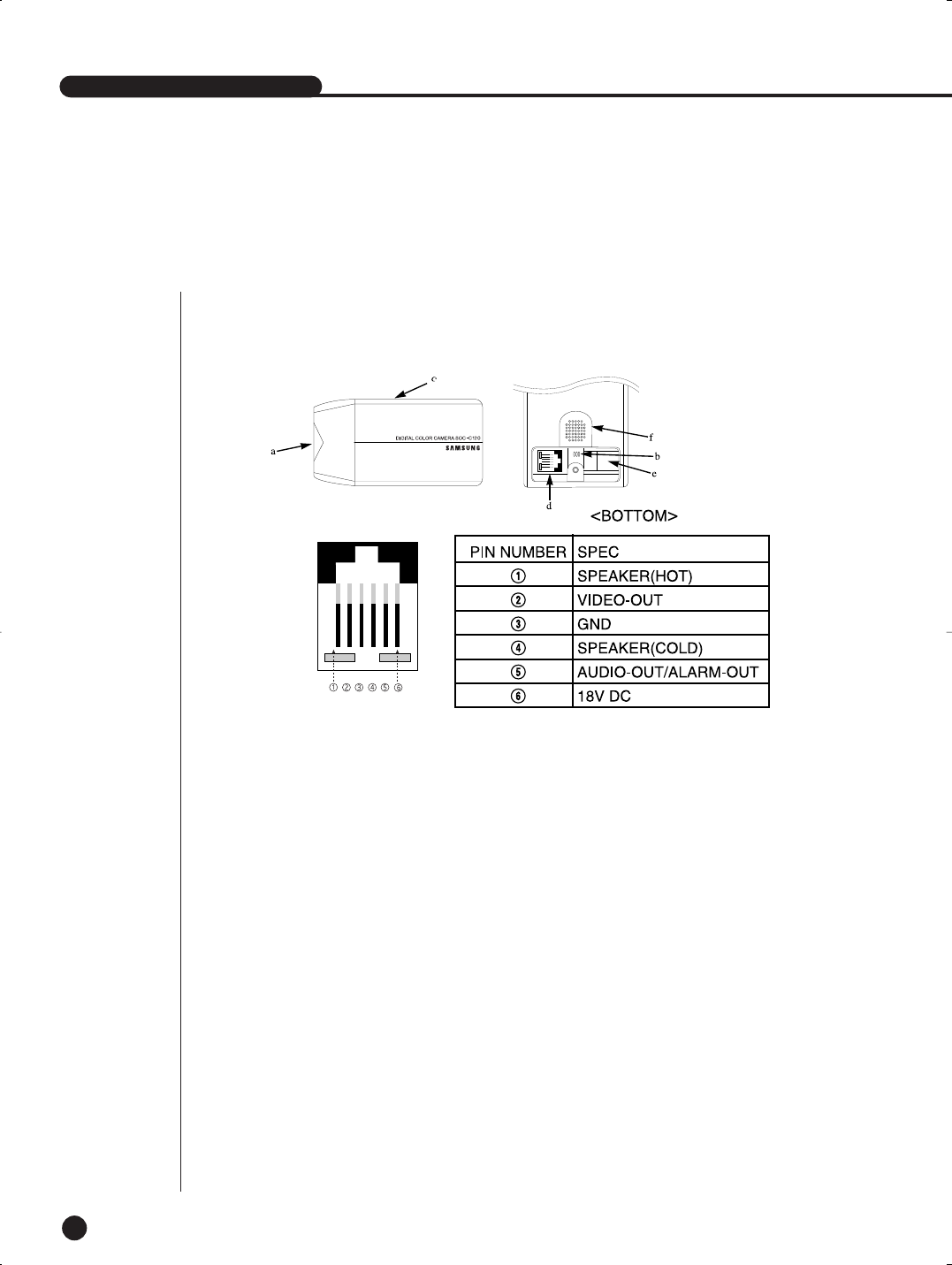
1) STANDARD CAMERA COMPOSITION (SOC-C120)
a. Lens
It has a focal length of 3.8mm and makes it possible for you to observe a relatively wide area.
b. Microphone
Capable of picking up all sound in the vicinity of the camera location and transmitting to the monitor.
c. Camera fitting groove
Enables the camera to be fixed onto the bracket. You may install it either above or below the camera if
necessary.
d. 6-pin modular jack
Used to connect the camera to the monitor.
e. SENSOR jack
Used to connect the sensor to the camera.
f. Speaker
Outputs the sound signal.
SHR-1040/SHR-1040K-ENG 2006.4.4 11:12 AM ˘ ` 2-9
EnglishEnglishEnglish
3-2
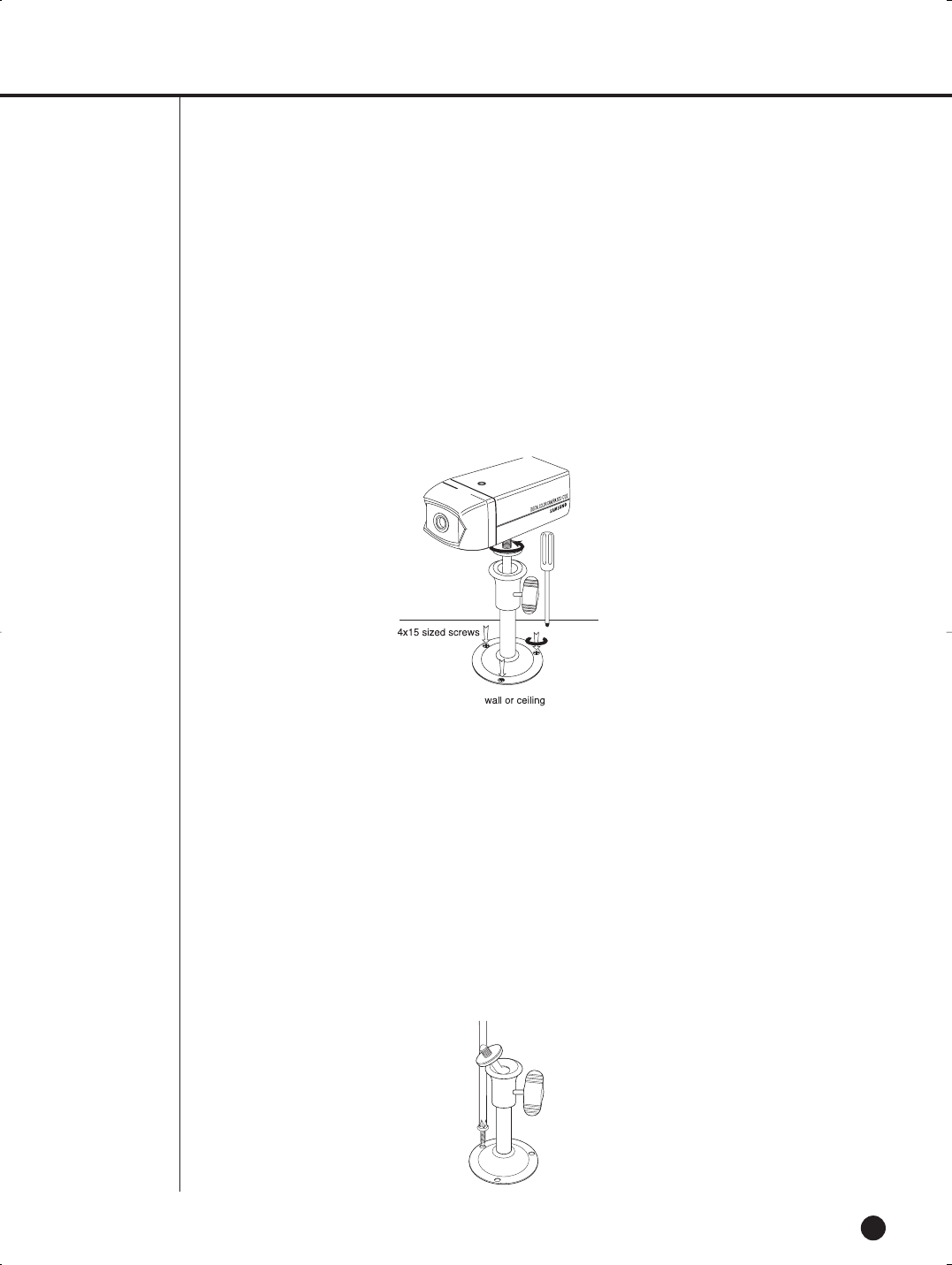
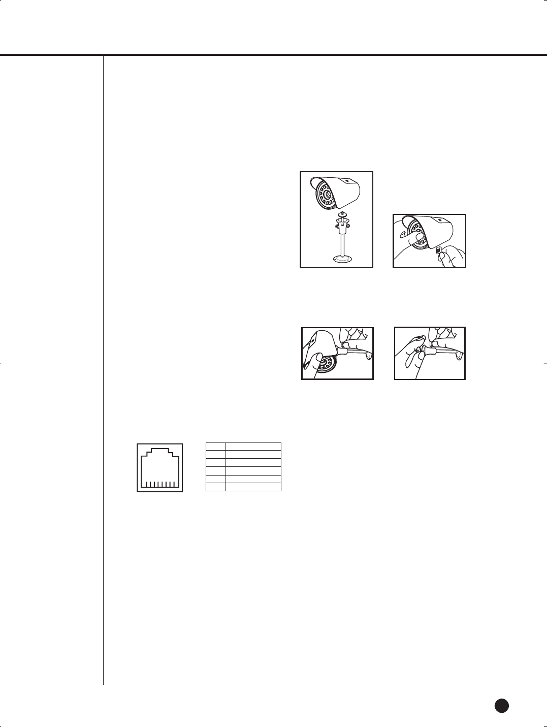
2) INSTALLING STANDARD CAMERA (SOC-C120)
SOC-C120 camera can be attached to the wall, ceiling or shelf using the camera mount bracket
(SBR-110S).
Choose an installation site that can sufficiently support the weight of the equipment to be installed.
Attach the camera mount bracket to the wall or ceiling using the supplied three screws
(M4 X L15).
Adjust the camera to target the video location and tighten the bracket handle on the camera mount
bracket.
3) CAMERA MOUNT BRACKET(SBR-110) & STANDARD CAMERA(SOC-C120)
(1) Overview
CAMERA MOUNT BRACKET (SBR-110S) is used to attach the camera to a wall, ceiling or shelf.
(2) Specifications
Use : Indoor
Installation : Wall or Ceiling
Dimensions : 2.25 (W) X 1.86(H) X 3.95(L) inches
Weight : 0.29 Ibs
Operating Temperature : 32°F ~ 104°F
(3) Accessories
SCREW (M4 X L15) : 3 pcs
(4) Installation
Explains the installation of CAMERA MOUNT BRACKET installation, as well as installation of the
camera onto the CAMERA MOUNT BRACKET.
• Choose an installation site that can sufficiently support the weight of the equipment to be installed.
• Attach the camera mount bracket to the wall using the supplied screws (M4 X L15).
SHR-1040/SHR-1040K-ENG 2006.4.4 11:12 AM ˘ ` 2-10
SHR-1040/1040K USER’S MANUAL
English
3-3
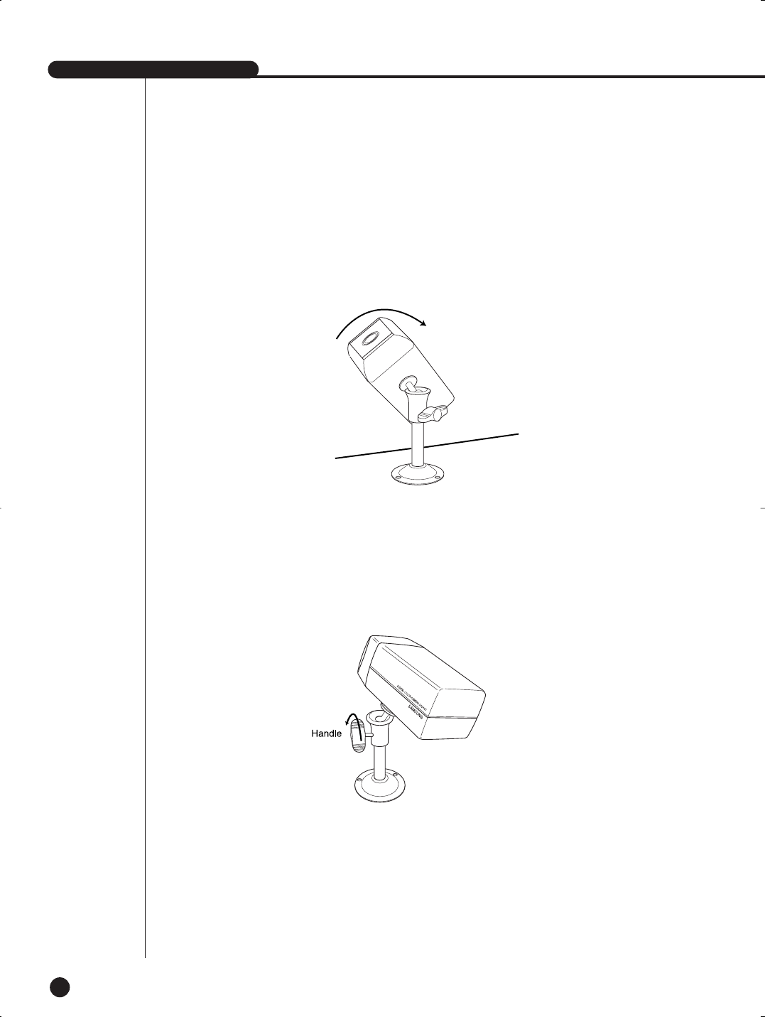
• Adjust the camera to target the video location and tighten the bracket handle on the camera mount
bracket. Install the camera on to the male screw of the Camera Mount Bracket by rotating the camera
in clockwise.
• Loosen the handle by turning it in a counter-clockwise direction and then adjust the camera position .
Tighten the handle, turning it clockwise, and lock the camera in position.
• Connect the camera cable to the camera.
SHR-1040/SHR-1040K-ENG 2006.4.4 11:12 AM ˘ ` 2-11
EnglishEnglishEnglish
3-4
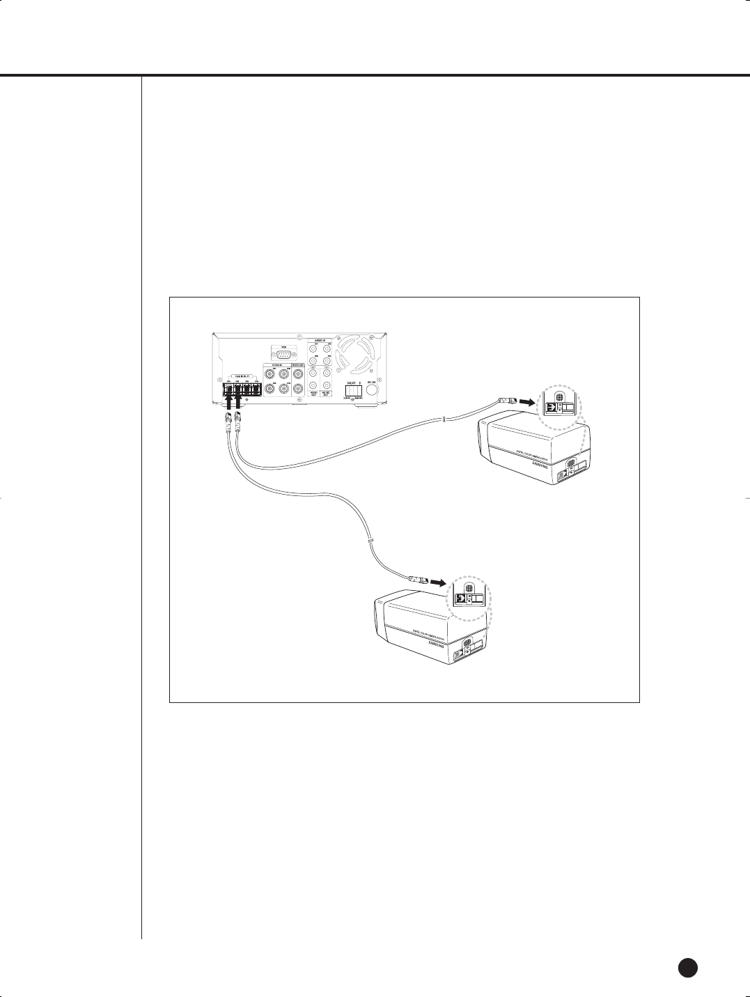
After positioning the monitor and installing four cameras in the desired location, please
connect the CAMERA to the DVR using the CAMERA CABLE (MCB-60) as shown
in the figure below.
Connection status checking method :
• Turn on the DVR after connecting cameras, and check if camera image is displayed.
• If the DVR and the camera are not connected properly, OSD ‘L’(LOSS) will be displayed on screen.
SHR-1040/SHR-1040K-ENG 2006.4.4 11:12 AM ˘ ` 2-12

SHR-1040/1040K USER’S MANUAL
English
3-5
1) Before Installation
SOC-N120 INTRODUCTION
SOC-N120 Nightvision camera is intended to be used exclusively with those sold by this company for
DIY. With the built-in IR LED and light sensor in the camera, both day monitoring and night monitoring
are possible. Also, since it is designed as water-proof daily product, it can be used not only indoors, but
also outdoors.
2) Precautions for Installation and Operation
Installing SOC-N120
* Make sure the installation location is a place where 5 times (about 1 kg) of the total weight of the cam-
era can be tolerated before installing the camera.
* When installing the camera, make sure the cable is not squeezed in an inappropriate place or the insu-
lation plastic is removed (it will be a cause for malfunction or fire).
* Keep personnel away from under the installation location because there is a risk of object falling during
installation. Move precious items to a safe place as well before the installation.
* Install SOC-N120 in a cool place where there is no direct sunlight.
* Do not expose SOC-N120 to direct sunlight during operation or storage.
* SOC-N120 should always be used in a place where certain temperature and humidity can be main-
tained (as specified below).
- Temperature: 14°F ~ 122°F
- Humidity: Below 90%
2
Nightvision Camera
SHR-1040/SHR-1040K-ENG 2006.4.4 11:12 AM ˘ ` 2-13
EnglishEnglishEnglish
3-6
SOC-N120 Pin Configuration
1 SP-
2 VIDEO_OUT
3 GND
4 SP+
5 ALM/AUDIO
6 VDD
3) Installation
1. Make sure the installation location is a place
where 5 times (about 2.2lbs) of the total weight
of the camera can be tolerated before installing
the camera.
2. Connect the cable below the camera after
attaching the provided Mount Bracket to the
desired place.
3. Use the handle on the Mount Bracket to
adjust the direction you want to setup for
monitoring.
SHR-1040/SHR-1040K-ENG 2006.4.4 11:12 AM ˘ ` 2-14
SHR-1040/1040K USER’S MANUAL
English
3-7
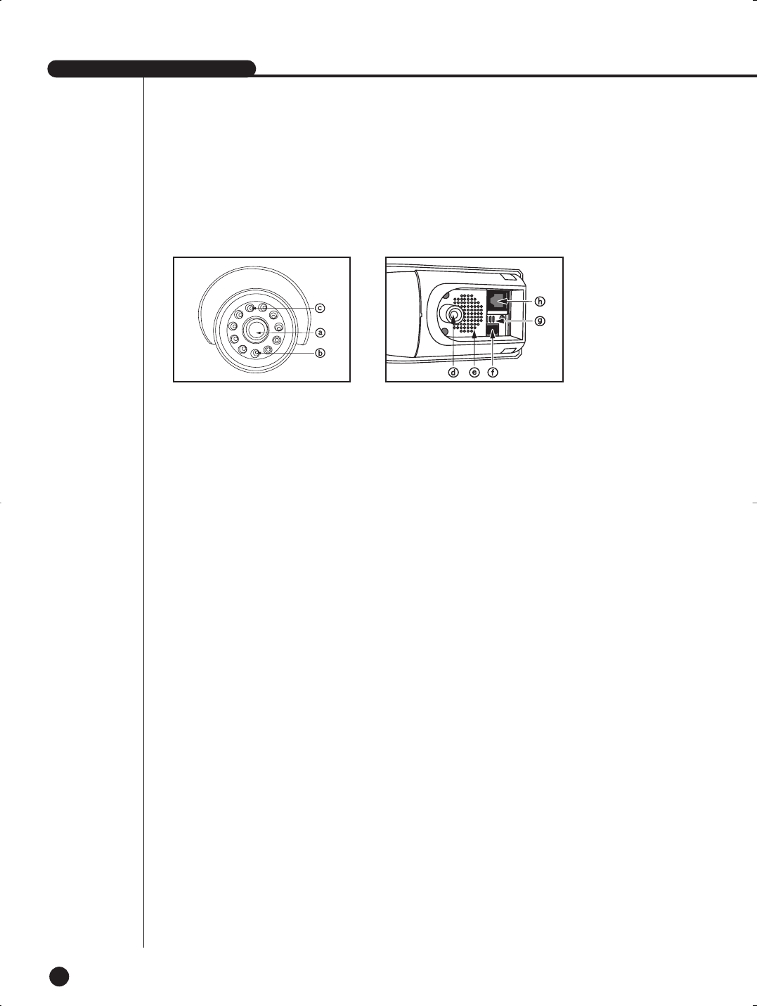
a). Lens
- It has a focal length of 3.8mm and makes it possiblefor you to observe a relatively
wide area.
b). Illumination Sensor
- Detects incoming light to control the IR LED.
c). IR LED
- This is an infrared LED that is controlled by the illumination sensor.
d). Camera fitting groove
- Enables the camera to be fixed onto the bracket. You may install it either above or
below the camera if necessary.
e). Speaker
- Used to connect the sensor to the camera.
f). SENSOR jack
- It outputs the sound signal which was transfered from alarm sensor.
g). Microphone
- Capable of picking up all sound in the vicinity of the camera location and
transmitting to the monitor.
h). 6-pin modular jack
- Used to connect the camera to the monitor or DVR.
4) Title of Each Component
SHR-1040/SHR-1040K-ENG 2006.4.4 11:12 AM ˘ ` 2-15

Chapter 4.
Connecting with
other device
4
English
SHR-1040/SHR-1040K-ENG 2006.4.4 11:12 AM ˘`3
SHR-1040/1040K USER’S MANUAL
English
4-1
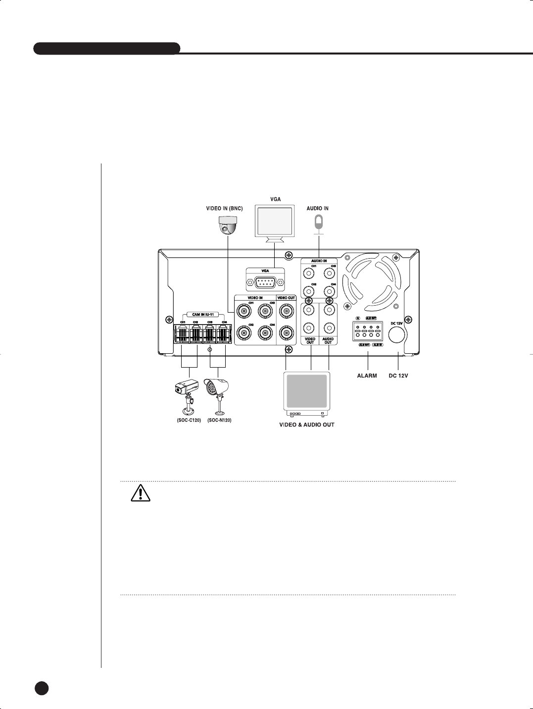
1
Connecting the Video, Audio, and Monitor
SHR-1040/1040K USER’S MANUAL
[SHR-1040]
Caution
Caution
- Do not connect the Video In (BNC Input) and the RJ-11 (DIY Camera) input with the same
channel at the same time. If connecting them simultaneously, two input signals may be
mixed when outputting. This is not the product defect; so, please connect only one between
the two inputs.
- When the first delivery, the Video output is set to the CVBS (BNC Output) output. If viewing
on the VGA Monitor, set it in the MENU first.(Refer to 6-12 page)
- The same Video signal is outputted for the BNC Out and the RCA Out of the Video out.
Use by connecting the desired port.
SHR-1040/SHR-1040K-ENG 2006.4.4 11:12 AM ˘ ` 3-1
EnglishEnglishEnglish
4-2
EnglishEnglishEnglishEnglishEnglish
2
Connecting the Alarm Input/Output
The Alarm IN/OUT port in the back of SHR-1040 is composed of the following
elements.
●ALARM IN/OUT Connection
ALM OUT
G
ALM IN
ALM RST
Name Function
ALARM Input Port1 ALM IN
ALARM Output Port2 ALM OUT
On receiving an ALARM RESET signal, the sys-
tem cancels the current ALARM input and output
signal and then resumes sensing.
3 ALM RST
SHR-1040/SHR-1040K-ENG 2006.4.4 11:12 AM ˘ ` 3-2

Chapter 5.
Basic Operation
5
English
SHR-1040/SHR-1040K-ENG 2006.4.4 11:12 AM ˘`5
SHR-1040/1040K USER’S MANUAL
English
5-1
1
System Operation
SHR-1040/1040K USER’S MANUAL
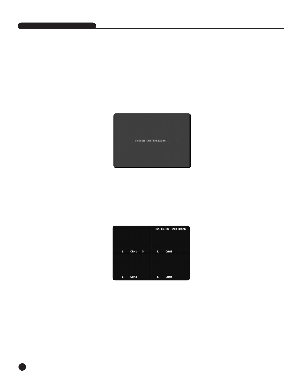
●When the adapter is connected to the DC 12V connector on the back panel, the Power LED
on the front is lit. The following screen appears, and the system is booted.
Turning Power On
●If no video signals exist when the system is turned on, the letter L (for Loss) lappears next
to the title (CAM1…CAM2) of the screen, and the screen turns black.
Connect a video signal, and the letter L will disappear. You can check the Video Loss Event
on the Loss Event List of the Search Menu.
Detection of Video In Signals
SHR-1040/SHR-1040K-ENG 2006.4.4 11:12 AM ˘ ` 4-1
EnglishEnglishEnglish
5-2
EnglishEnglishEnglish
2
Live Screen Mode
Full Display Screen
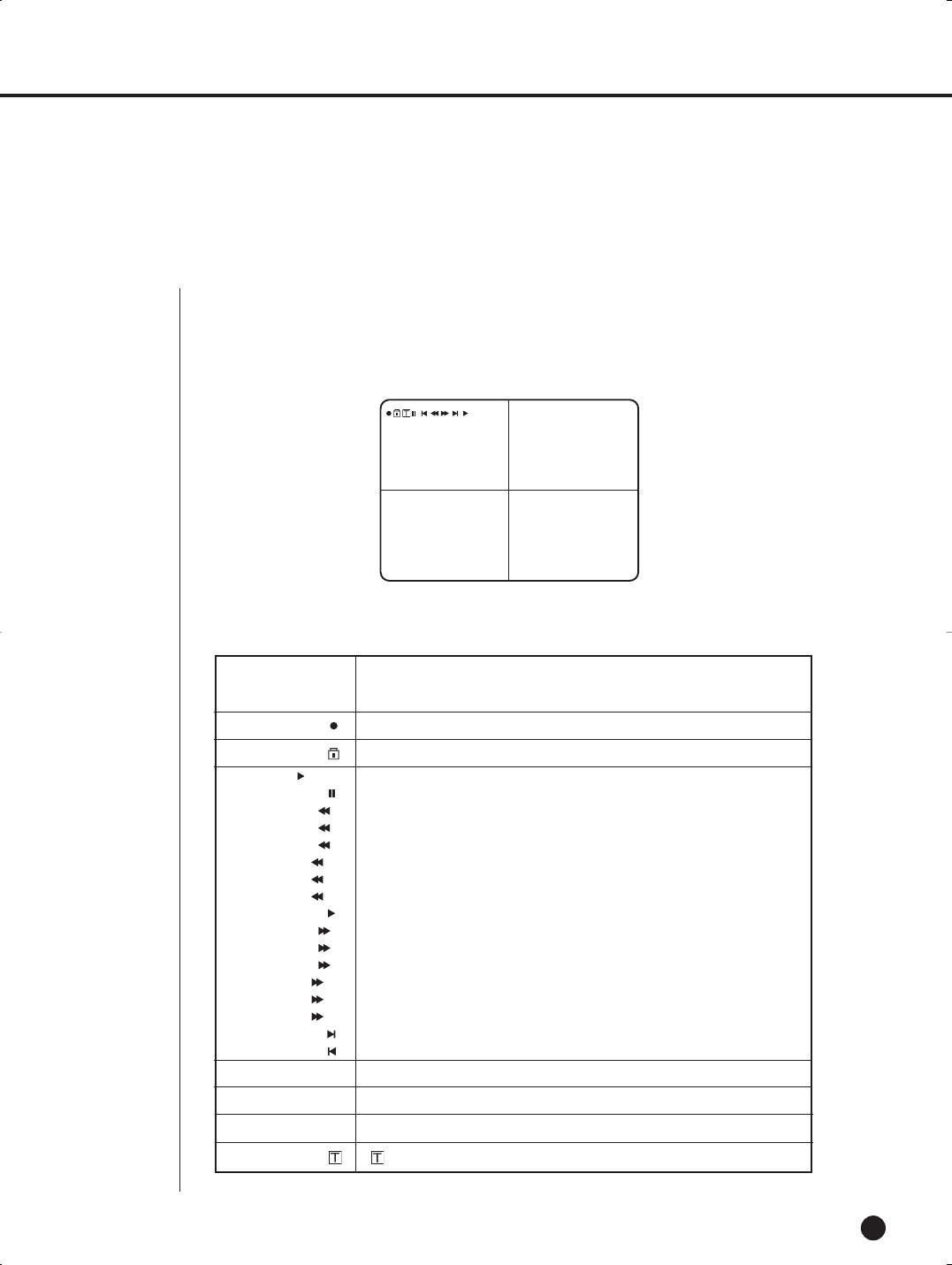
Markers and displays on the screen are seen as below.
01/01/06 12:00:00Play
AML CAM 2
AML CAM 4
AML CAM 1
AML CAM 3
S
For Live, it indicates the current time and date as set in the system.
For playback, it indicates the time and date of the data recording.
PLAY
2
4
8
16
32
64
2
4
8
16
32
64
Indicates playback at normal speed.
Indicates pause.
Indicates X2 reverse playback.
Indicates X4 reverse playback.
Indicates X8 reverse playback.
Indicates X16 reverse playback.
Indicates X32 reverse playback.
Indicates X64 reverse playback.
Indicates X1 forward playback.
Indicates X2 forward playback.
Indicates X4 forward playback.
Indicates X8 forward playback.
Indicates X16 forward playback.
Indicates X32 forward playback.
Indicates X64 forward playback.
Used for cut-by-cut search in reverse direction during pause.
Used for cut-by-cut search in reverse direction during pause.
05/05/01 00:00:01
marker is displayed when the system in recording mode.
A marker appears when the system is in Alarm recording mode.
Indicates the VIDEO LOSS state.
M marker appears when the system is in Motion record mode.
marker appears when the system is in Time record mode.
A
L
M
Prevents the cancellation of REC.
SHR-1040/SHR-1040K-ENG 2006.4.4 11:12 AM ˘ ` 4-2
SHR-1040/1040K USER’S MANUAL
English
5-3
3
Key Functions
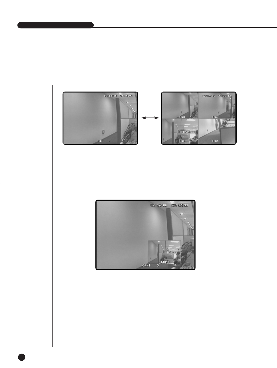
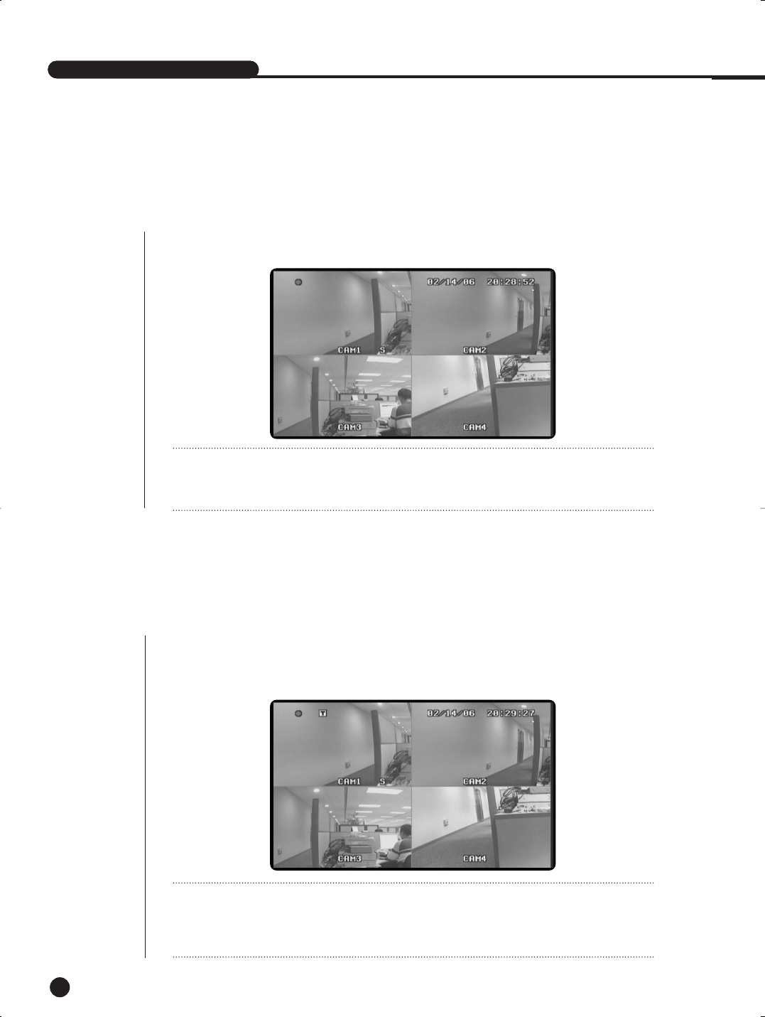
●Use the CHANNEL Key when you want to view the channel in full screen.
●Press the desired channel key to view the channel in full screen.
●Audio of the channel is also selected. The S mark appears next to the title of the selected
channel, and the audio of the channel is off.
●Audio recording is available for the one selected channel.
●Press the MODE Key to view the 1CH MODE and the QUAD MODE in turn as shown in the
picture.
●Use the PIP Key to view the main and the sub screen at the same time.
●You can view the two channels when pressing the PIP button in the 1CH mode.
●Press the ENTER Key in PIP mode to switch the main and sub screen.
●Press the PIP Key again to exit the PIP state and enable the Single screen mode.
●Press the FREEZE Key to freeze the main screen only. On the top right of the screen,
‘||’(FREEZE MARK) appears.
●Clear the Freeze before operating another key.
●Press the Sequence Key in the PIP mode PIP to automatically sequence to the sub screen.
(Auto sequence is cleared when pressing the Sequence Key again.)
☛Sequence in the PIP MAIN CHANNEL 1 screen
SUB2 ➝SUB3 ➝SUB4 ➝SUB2
1. CHANNEL KEY & MODE KEY
2. PIP KEY
SHR-1040/SHR-1040K-ENG 2006.4.4 11:12 AM ˘ ` 4-3
4-4
EnglishEnglishEnglishEnglishEnglishEnglishEnglish
5-4
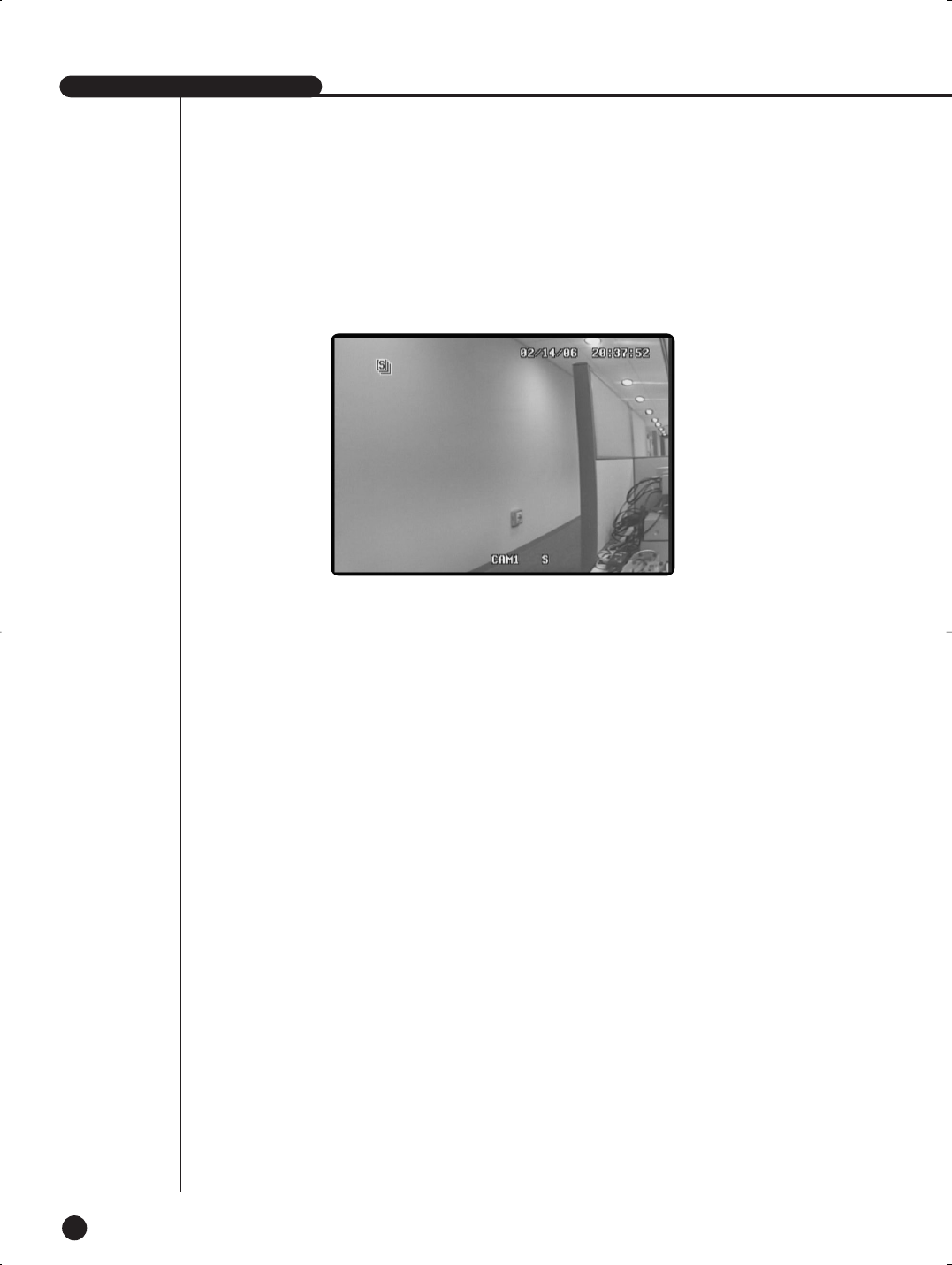
●The FREEZE Key is used to pause the screen.
●Press the Freeze Key to display the‘II’marker on the top right. The screen is paused.
Press the Freeze Key again to make the‘II’marker disappear and clear the pause screen.
4. FREEZE KEY
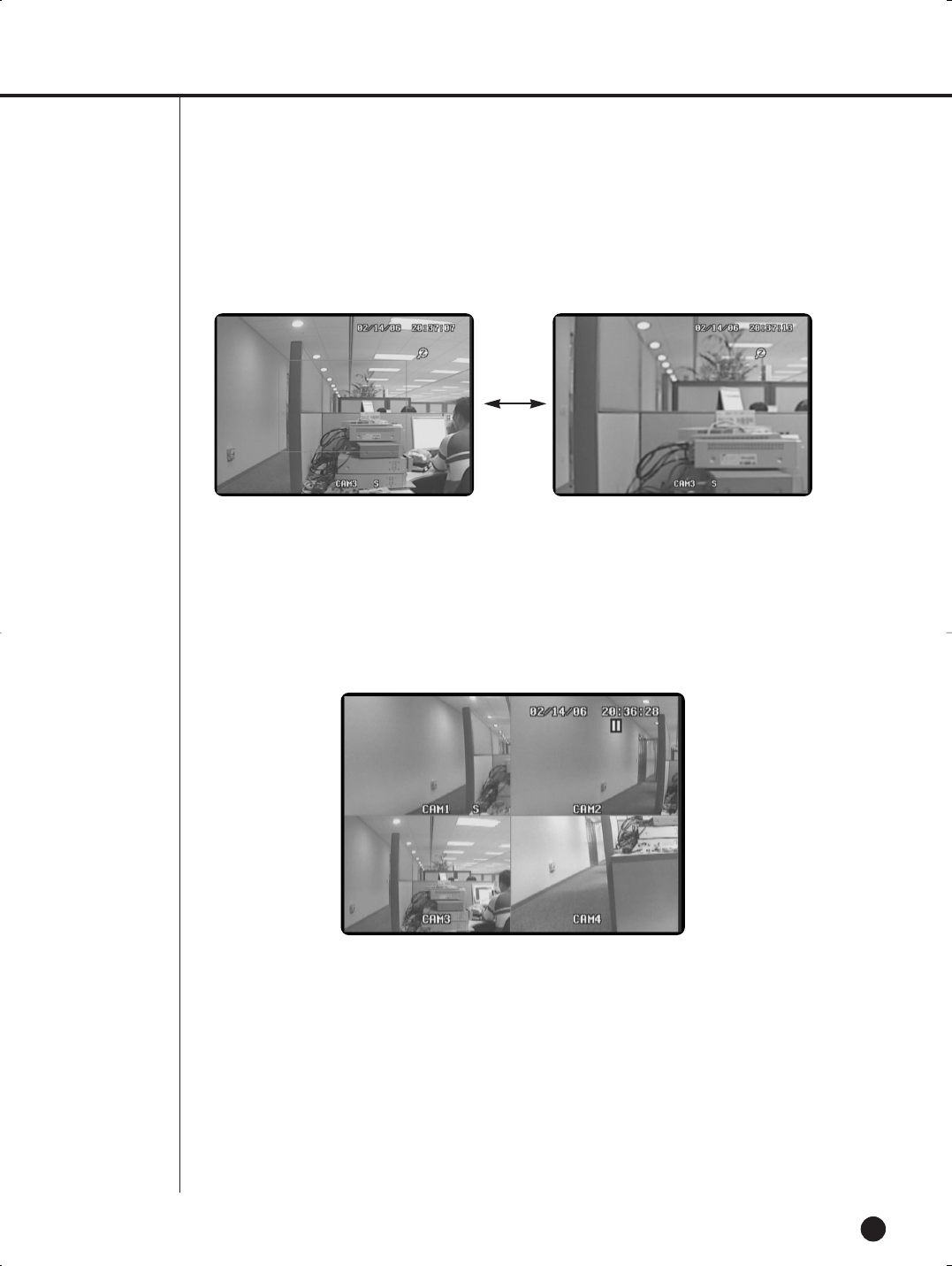
●The ZOOM Key is used to X2 zoom the selected area in 1CH mode.
●Press the ZOOM Key to display the ZOOM area (default: Center Area).
●Press the ZOOM Key repeatedly to display or clear the ZOOM area.
●Press the ZOOM Key to zoom the selected area, and press the ENTER key to clear the
ZOOM and display the marked area.
●ZOOM function is operated in the Single screen mode. SINGLE.
3. ZOOM KEY
SHR-1040/SHR-1040K-ENG 2006.4.4 11:12 AM ˘ ` 4-4
SHR-1040/1040K USER’S MANUAL
English
5-5
●The Sequence Key is used for automatic channel sequencing. It is enabled only in Live Mode.
●Channels are switched in sequence and the Loss channel without video signals are skipped
during the Dwell Time set by the Setup Menu.
(Switch from 1channel ➝2 channel)
☛Sequence in the Full Screen
CH1 ➝CH2 ➝CH3 ➝CH4 ➝CH1 ➝CH2 ➝CH3 ➝CH4 ➝......
☛Sequence of the Main Channel 1 in the PIP Screen
SUB2 ➝SUB3 ➝SUB4 ➝SUB2 ➝......
●Cancel the alarm when alarm is enabled.
5. SEQUENCE KEY
6. ALARM KEY
SHR-1040/SHR-1040K-ENG 2006.4.4 11:12 AM ˘ ` 4-5

Chapter 6.
Menu Setup
English
6
SHR-1040/SHR-1040K-ENG 2006.4.4 11:12 AM ˘`5
SHR-1040/1040K USER’S MANUAL
English
6-1
1
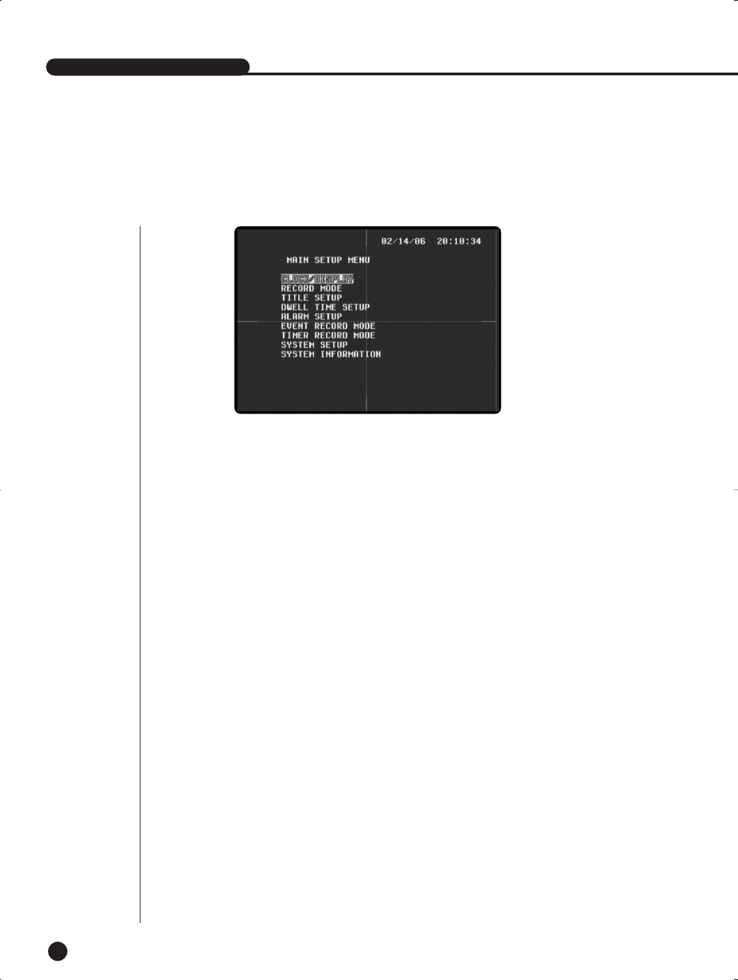
Main Setup Menu
1. CLOCK/DISPLAY
- Set the time, date and display items.
2. RECORD MODE
- Set record-related items.
3. TITLE SETUP
- Set channel titles.
4. DWELL TIME SETUP
- Set the dwell time for each channel for sequence operations.
5. ALARM SETUP
- Set the alarm channels and setup/alarm-related items.
6. EVENT RECORD MODE
- Set the recording and motion detection items when the alarm is on.
7. TIMER RECORD MODE
- Set the time record.
8. SYSTEM SETUP
- Set the initiation of the system and the password.
9. SYSTEM INFORMATION
- Displays the HDD capacity and the system software version.
SHR-1040/1040K USER’S MANUAL
SHR-1040/SHR-1040K-ENG 2006.4.4 11:12 AM ˘ ` 5-1
EnglishEnglishEnglish
2
Clock/Display Setup
6-2
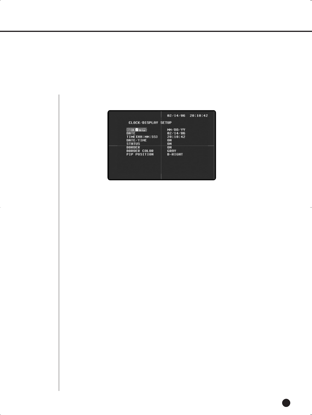
●Set the time, date and display items.
(1) DATE TYPE
- Date can be displayed in three types, and the user can choose one among the three.
[YY/MM/DD, MM/DD/YY, DD/MM/YY]
(2) DATE
- Set the present data.
(3) TIME [HH:MM:SS]
- Set the present time.
(4) DATE/TIME
- Set the date/time to ‘‘On’’ to display it on the screen, set the date/time to ‘Off’ to not display it.
[ON/OFF]
(5) STATUS
- Set the system status ‘On’ to display playback information when record or play back recorded video,
and set the status to ‘Off’ to not display such information.
[ON/OFF]
(6) BORDER
- Display or hide the border of the screen. Set the border to ‘On’ to display the border, and set the bor-
der ‘Off’ to not display the border.
[ON/OFF]
(7) BORDER COLOR
- The border color can be defined in three colors.
[GRAY/WHITE/BLACK]
(8) PIP POSITION
- Set the location of the sub screen.
[B-RIGHT/B-LEFT/T-RIGHT/T-LEFT]
SHR-1040/SHR-1040K-ENG 2006.4.4 11:12 AM ˘ ` 5-2
SHR-1040/1040K USER’S MANUAL
English
6-3
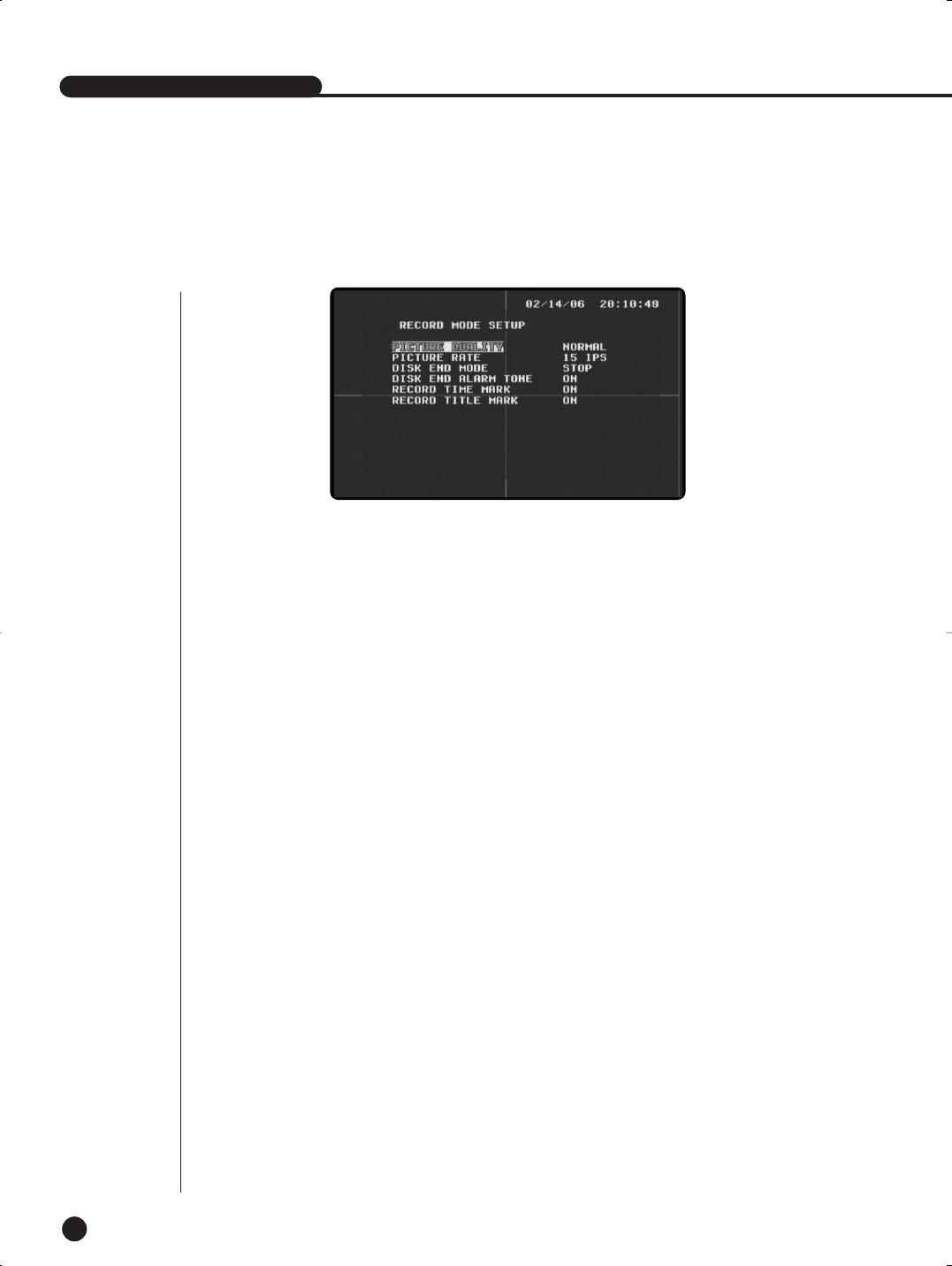
(1) PICTURE QUALITY
- Define the picture quality in three steps when recording. High means top quality, followed by
Normal and Low.
[NORMAL/HIGH/LOW]
(2) PICTURE RATE
- Set the number of record fields for video In.
[1/2.5/3.75/7.5/15/30]
(3) DISK END MODE
- When the mode is set to Stop, recording is stopped if the HDD becomes full during recording.
- When the mode is set to Continue, new data overwrites previously recorded data during recording. The
oldest data saved will be overwritten first.
[CONTINUE/STOP]
(4) DISK END ALARM TONE (HDD-full alarm mode)
When the Disk End mode is set to Stop, the alarm tone rings if the HDD becomes full during recording
if the tone is ‘On.’ The alarm tone does not ring if the tone is ‘off’. The tone is enabled when the Disk
End Mode is set to Stop.
[ON/OFF]
(5) RECORD TIME MARK (Record time display)
- When the mark is set to ‘On’, the time of recording is displayed during playback. When the mark is set
to ‘Off’, the time is not displayed.
[ON/OFF]
(6) RECORD TITLE MARK (Record title display)
- When the mark is set to ‘On,’ the title of recording is displayed during playback. When the mark is set
to ‘Off,’ the title is not displayed.
[ON/OFF]
3
Record Mode Setup
SHR-1040/SHR-1040K-ENG 2006.4.4 11:12 AM ˘ ` 5-3
EnglishEnglishEnglish
6-4
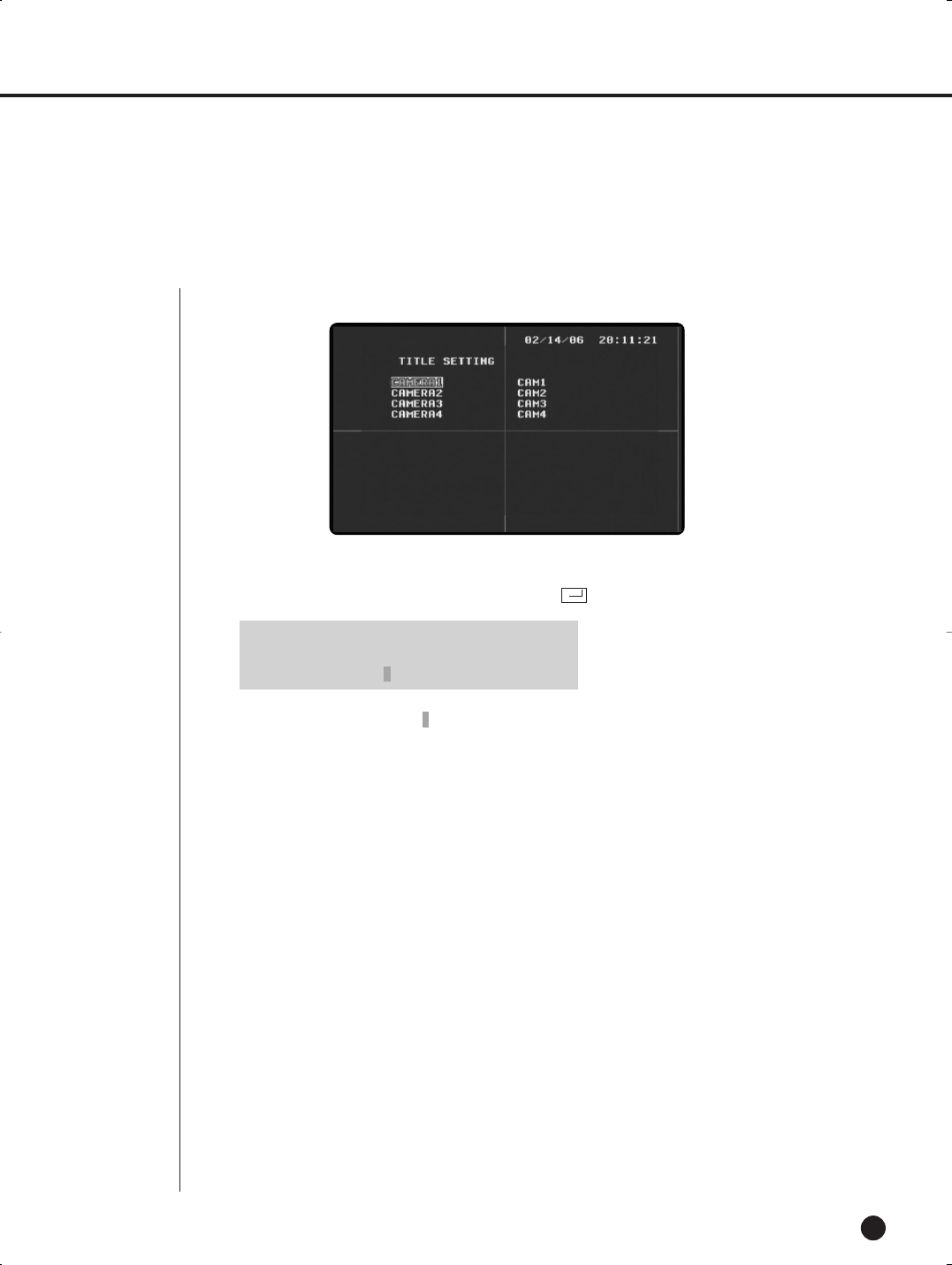
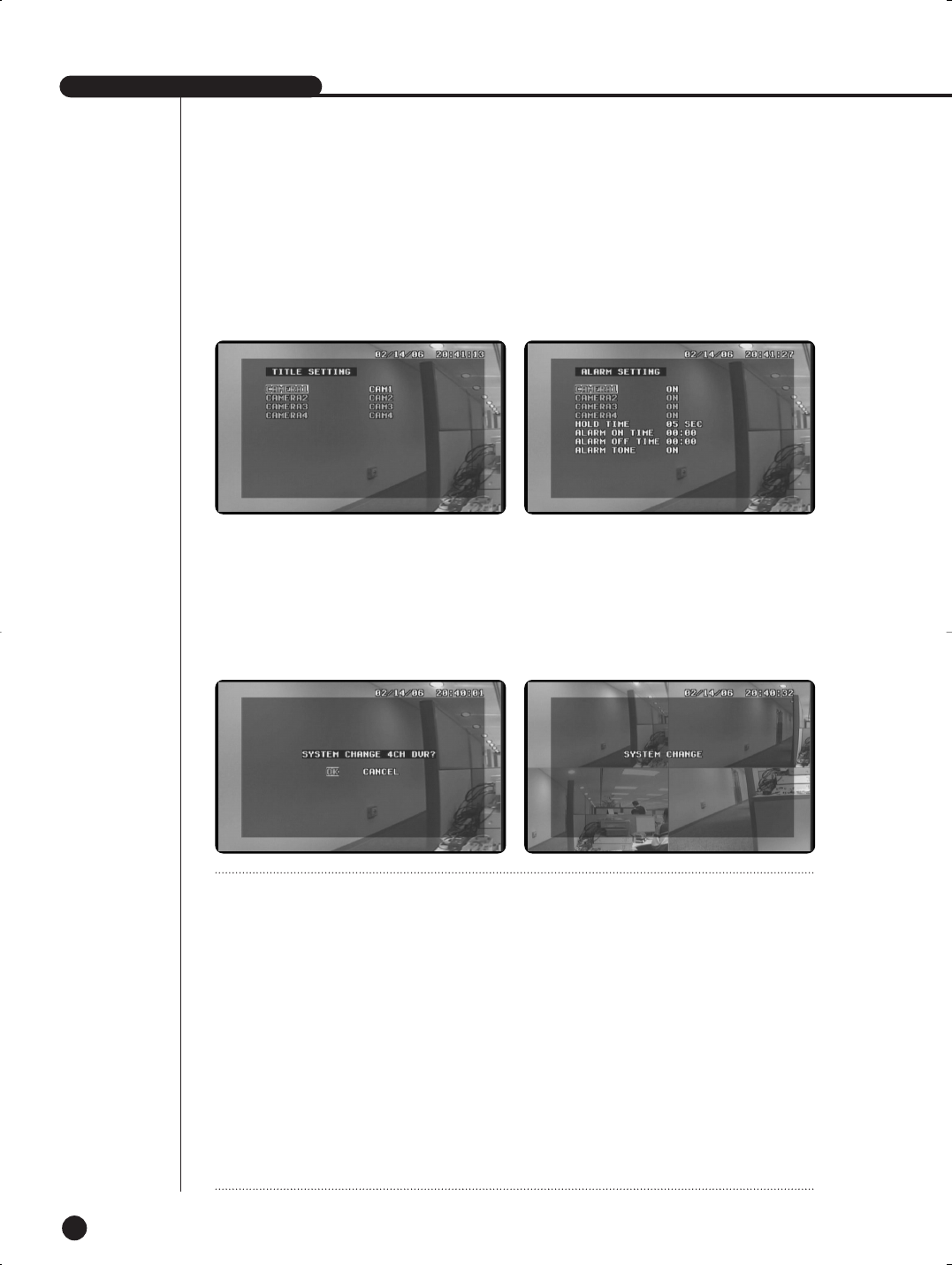
(1) TITLE SETUP
- You can set the title of each channel as you want.
- You can change the title by using …,†,œ,√,
- Place the cursor on the “ ” area when the title is not displayed. Press Enter to
delete OSD.
4
Title Setup
●The default settings of the title setup menu are shown as follows.
➛
0 1 2 3 4 5 6 7 8 9
ABCDEFGHIJKLMNOPQRSTUVWXYZ
: = . ( ) [ / ] _ + -
SHR-1040/SHR-1040K-ENG 2006.4.4 11:12 AM ˘ ` 5-4
SHR-1040/1040K USER’S MANUAL
English
6-5
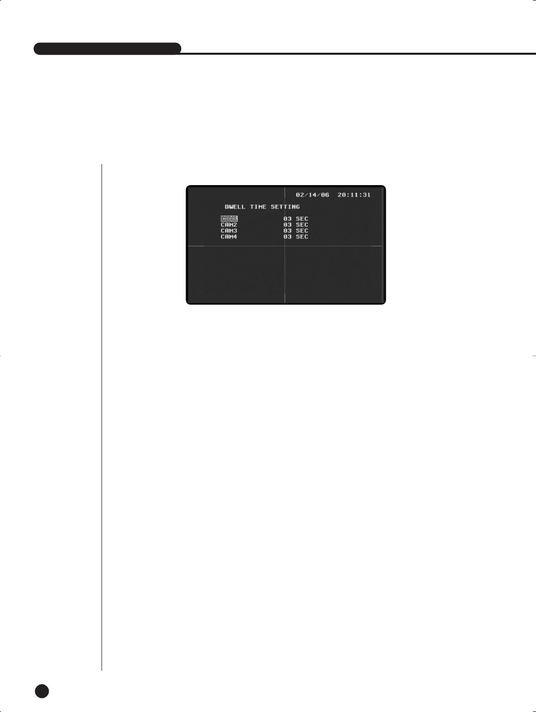
(1) DWELL TIME SETUP
- Press the Sequence button in single screen to enter Sequence Mode. You can set the dwell time of
each channel before switching.
When the Dwell Time is set to 0 seconds, the channel is skipped and the next channel appears.
[0SEC, 1SEC, 2SEC, 3SEC.................... ~ 60SEC]
5
Dwell Time Setup
●The default settings of the Dwell Time are shown as follows.
SHR-1040/SHR-1040K-ENG 2006.4.4 11:12 AM ˘ ` 5-5

EnglishEnglishEnglish
6-6
(1) ALARM SETUP
- Set the alarm setup to ‘ON’ to enable the alarm of each camera. Set the setup to ‘OFF’ to disenable
alarm. [ON/OFF]
(2) HOLD TIME
- When Alarm occurs, set the hold time of alarm.
[5SEC, 6SEC, 7SEC, 8SEC ~ 59SEC , 1MIN, 2MIN, 3MIN ~30MIN]
(3) ALARM ON TIME
- Set the start time of alarm operation. When the ALARM ON TIME and the ALARM OFF TIME are set,
alarm is detected during the period.
[00:00~23:59]
(4) ALARM OFF TIME
- Set the end time of alarm operation.
[00:00~23:59]
(5) ALARM TONE
- When the ALARM TONE is set to ‘ON’, the Alarm Tone rings when alarm is detected.
[ON/OFF]
6
Alarm Setup
●The default settings of the Alarm Setup Menu are shown as follows.
SHR-1040/SHR-1040K-ENG 2006.4.4 11:12 AM ˘ ` 5-6
SHR-1040/1040K USER’S MANUAL
English
6-7
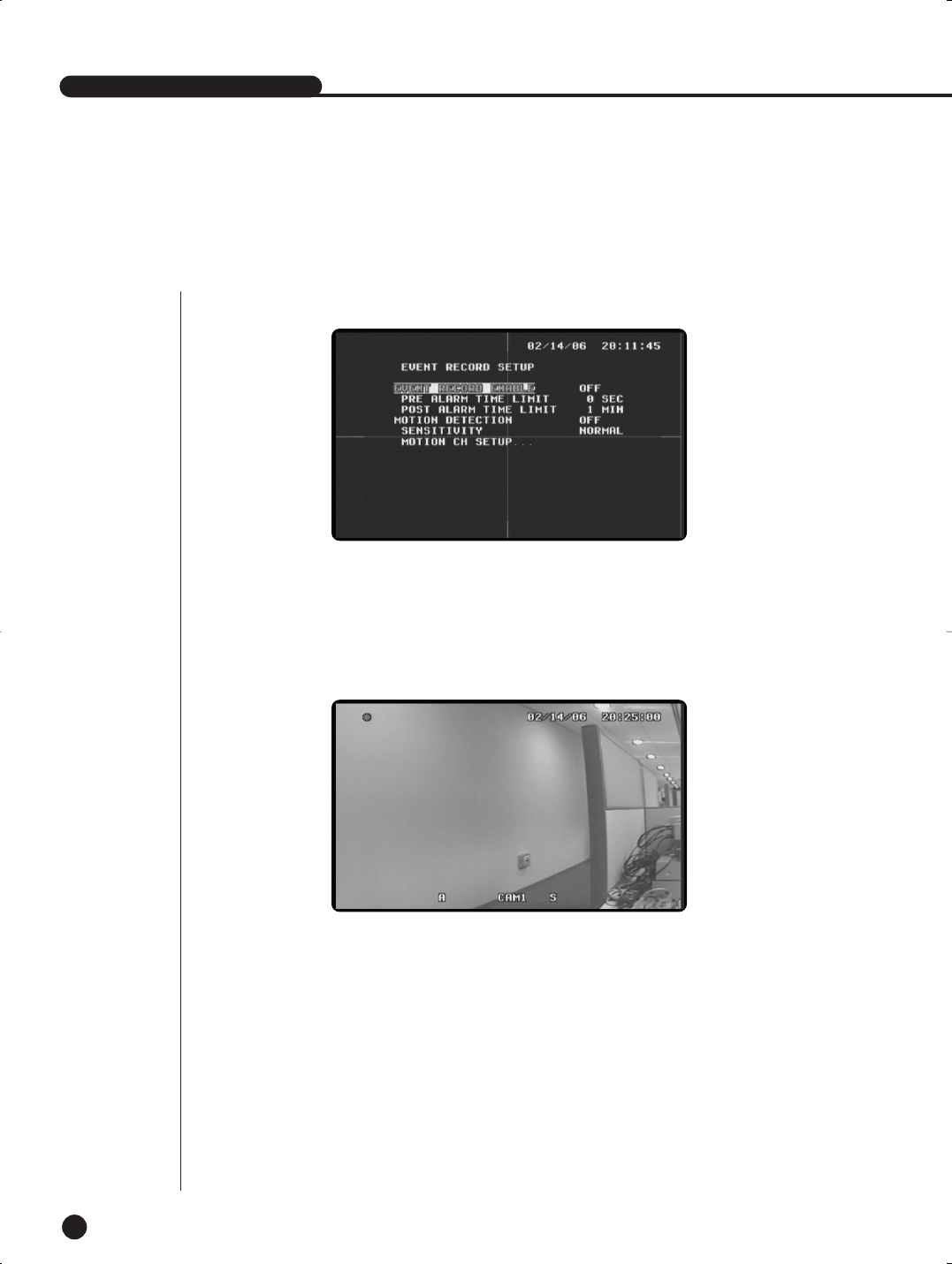
(1) EVENT RECORD ENABLE
Set the EVENT RECORD ENABLE to ‘On’ to start recording when alarm occurs, and set the EVENT RECORD
ENABLE to ‘Off’ to not start recording when alarm occurs. If you exit the menu after setting the EVENT RECORD
ENABLE to ‘On’, the system records data whenever an alarm occurs.
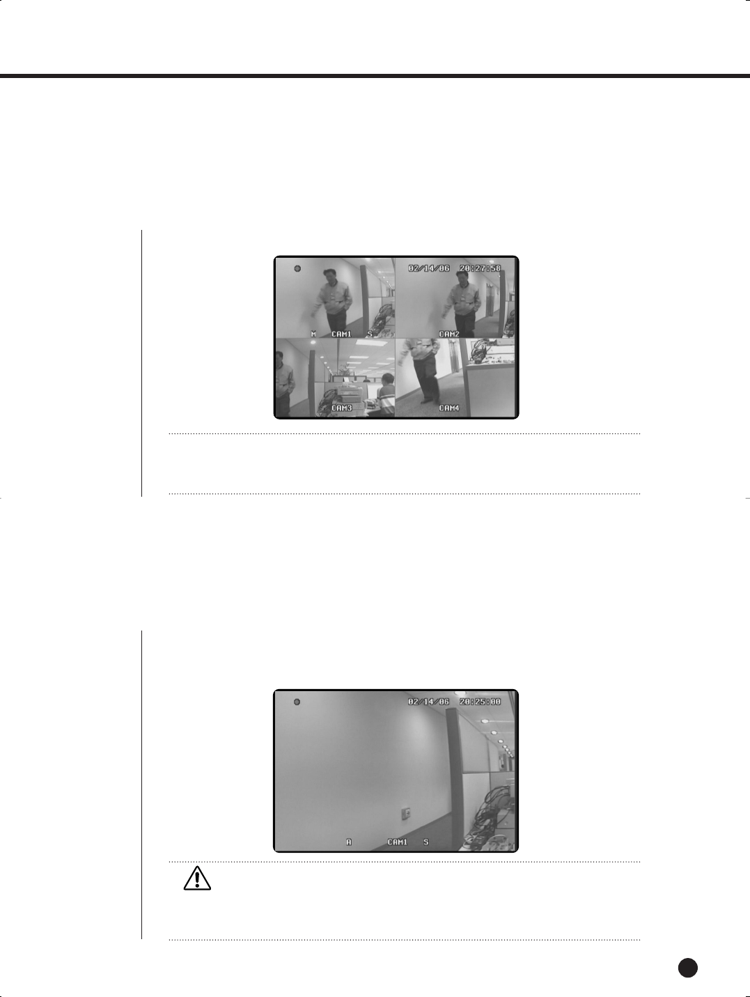
The following screen shows that the system records a program after an alarm occurs. The ‘A’ mark before the title of
the channel indicates that an alarm occurred.
[ON/OFF]
(2) PRE ALARM TIME LIMIT
- The Pre Alarm Time Limit enables users to know the state of the system before a motion is detected
or an alarm occurs. It decides the length of time for recording video and audio data input right before
motion or alarm. The system always stores 0 to 5second-long video and audio data in the memory,
and records data during the pre-set time set by the Time Limit in HDD when alarm recording starts.
[ 0, 1SEC, 2SEC, 3SEC, 4SEC, 5SEC ]
(3) POST ALARM TIME LIMIT
- After recording data as set by the MAIN ALARM TIME, the system records additional sec-
onds as set by the POST ALARM TIME Limit.
[10SEC ,20SEC ,30SEC ,1MIN ,2MIN ,3MIN ,4MIN , 5MIN]
7
Event Record Mode Setup
●The default settings of the Alarm/Motion Recording Setup menu are shown as follows.
SHR-1040/SHR-1040K-ENG 2006.4.4 11:12 AM ˘ ` 5-7
EnglishEnglishEnglish
6-8
(4) MOTION DETECTION
- When the Motion Detection is set to ‘ON’, the system records input video whenever a
motion is detected.
[ON/OFF]
(5) SENSITIVITY
- You can set the level of sensitivity of motion detection when setting motion detection.
HIGH/NORMAL/LOW. High indicates the highest level of sensitivity of motion detection,
and Low indicates the lowest level of sensitivity of motion detection.
[HIGH, NORMAL, LOW]
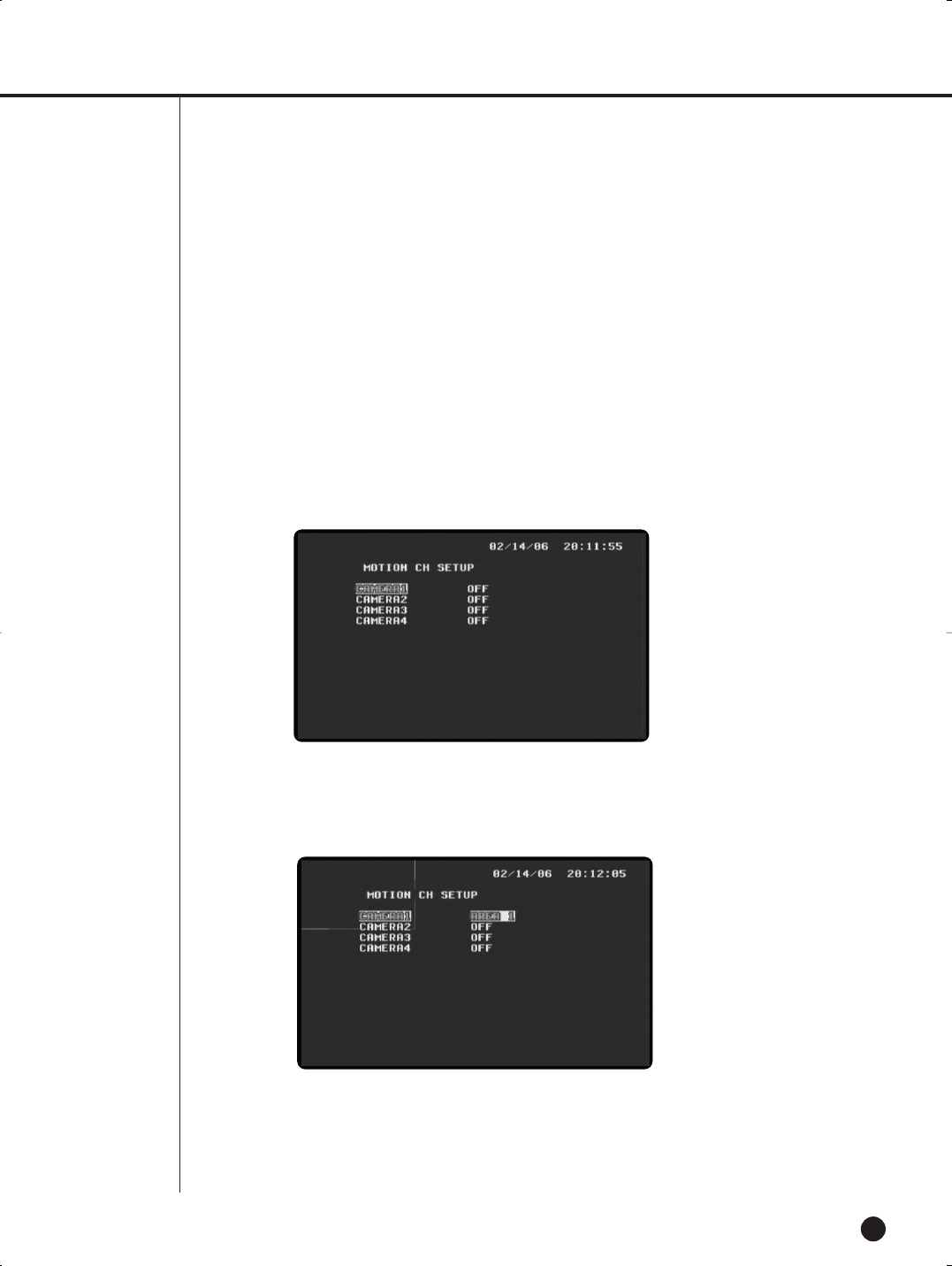
(6) MOTION CH SETUP
- Set the channel from which a motion is detected.
- You can divide the motion detection area into total 9 for each channel.
The following screen displays to activate only No. 1 area of No. 1 channel. You can use the direction key to
move the area around and select FULL for the motion detection on the whole screen.
With MOTION DETECTION set to ON, if no motion is detected in the specified area while a motion is sensed in
other areas, MOTION DETECTION will not operate.
SHR-1040/SHR-1040K-ENG 2006.4.4 11:12 AM ˘ ` 5-8
SHR-1040/1040K USER’S MANUAL
English
6-9
(1) TIMER: Set the Timer to ‘On’ to enable timer recording. [ON/OFF]
(2) DAY: Set the day of the week to record data.
[MON, TUE, WED, THU, FRI, SAT, DAILY, SUN]
(3) START & END: Set the start and ending time of recording. [00:00~23:59]
(4) FIELD RATE: Set the number of fields to record per second.
[1/2.5/3.75/7.5/15/30]
8
Timer Record Setup
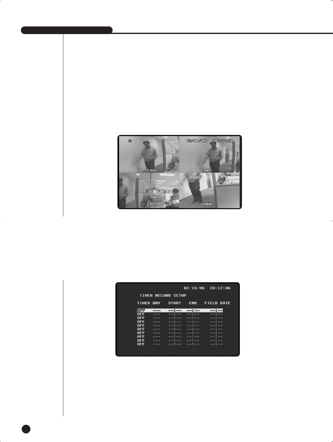
- Motion is detected only from channels set to ‘On.’
The following screen shows motion recording after motion detection. A motion is deteced in the
Channel 1. The ‘M’ mark before the title of each channel indicates that a motion is
detected.
[ON/OFF]
SHR-1040/SHR-1040K-ENG 2006.4.4 11:12 AM ˘ ` 5-9
EnglishEnglishEnglish
6-10
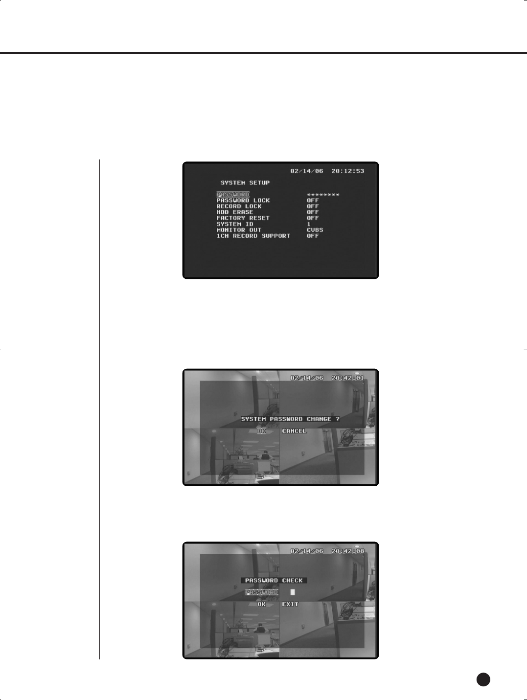
(1) PASSWORD
- The default password : 4321
- You can set the password to limit access to the Main Screen setup by unauthorized people.
(Create a four-digit password by choosing between 1~4.)
You can enter the password from No. 1 to No. 4 using the corresponding channel key.
Once the password is entered, you’ll see the following message that asks if you want to change the password. If
you want to change it, click OK and if not, click CANCEL.
(2) PASSWORD LOCK
When the user sets the Password Lock after setting a password, he or she has to enter the password
whenever entering the menu.
[ON/OFF]
9
System Setup
SHR-1040/SHR-1040K-ENG 2006.4.4 11:12 AM ˘ ` 5-10
SHR-1040/1040K USER’S MANUAL
English
6-11
(3) RECORD LOCK
If you set RECORD LOCK to ON and press STOP to release the current recording, you are prompted to
enter the PASSWORD.
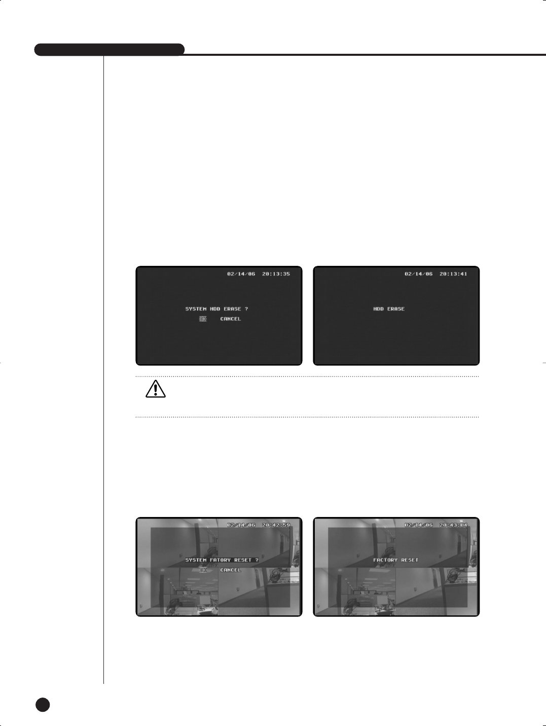
(4) HDD ERASE
If you exit the Menu after setting HDD ERASE to ON, you will see the following message that asks if you
want to erase the data on the HDD. If you click OK, you’ll see “HDD ERASE” as in the next picture, and the
existing HDD Data is erased. If you click CANCEL, the HDD data will not be erased.
[ON/OFF]
(5) FACTORY RESET
When FACTORY RESET is enabled, the settings are reset to the factory default.
If you exist the menu after setting FACTORY RESET to ON, you’ll see the following mes-
sage that asks if you want to perform FACTORY RESET. If you click OK, the settings are
reset to the factory default with a message of “FACTORY RESET” as in the next picture. If
you click CANCEL, FACTORY RESET will not perform.
[ON/OFF]
Caution
Caution
Deleted data cannot be restored. Check data carefully again before deleting data.
SHR-1040/SHR-1040K-ENG 2006.4.4 11:12 AM ˘ ` 5-11
EnglishEnglishEnglish
6-12
(6) SYSTEM ID
Set the System ID to use the Remote Controller.
When using more than one unit of the system, a number of systems may be operated at the same time
with a single remote controller. Set the different IDs for different units.
Press the System ID of the Remote Controller and use the number keys to create IDs.
After the setting, systems with IDs that correspond to the ID of the remote controller will operate.
[0,1,2 ~ 8,9]
(7) MONITOR OUT
Selects the Video Out of the System.
When the Video Out is set at CVBS, the video out is sent through BNC and RCA Video Output port.
When the Video Out is set at VGA, the video out is sent through VGA Video Out port, and seen on the
PC monitor. After changing the settings and existing the menu, the system is automatically rebooted.
After rebooting, the change is applied.
[CVBS/VGA]
(8) 1CH RECORD SUPPORT
If you set 1CH RECORD SUPPORT to ON, the system switches from 4-channel to 1-channel mode.
Then, a selected channel will be the number 1 channel.
If you exist the menu after setting 1 CH RECORD SUPPORT to ON, you will see the following
message that asks if you want to change the SYSTEM into 1 channel mode. If you click OK, the
system switches.
SHR-1040/SHR-1040K-ENG 2006.4.4 11:12 AM ˘ ` 5-12
SHR-1040/1040K USER’S MANUAL
English
6-13
Once the system switched to 1 channel mode, all system functions operate in 1 Channel mode and
the items of other channels in the MENU are deactivated.
Once the system switched to 1 channel mode, you can just play the data in this mode and the data recorded in 4
Channel mode could not be played. On the contrary, in 4 Channel mode, the data recorded in Channel 1 mode will
not be run and only the data recorded in 4 Channel can be played.
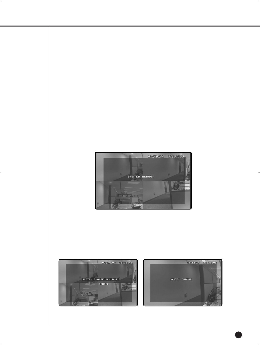
If you want to switch from 1 channel mode back to 4 channel mode, set 1CH RECORD SUPPORT to OFF and exit
the MENU. Then, you will see the following message that asks if you want to switch the system mode. If you click
OK, the system will be switched.
Note
Note
The hidden key is a shortcut key that is used in the following cases:
- If you have set the password lock but don’t remember the password, so that you couldn’t access the menu.
- If the current settings of MONITOR OUT does not match those of the current monitor connected, so that
you couldn’t see the display.
Press and hold down one of the hidden keys below for 5-10 seconds to activate it.
1. MODE KEY + CH1: MONITOR OUT Changes the settings of MONITOR OUTPUT. Once the settings are
changed, the system automatically reboots. Connect the monitor that matches the changes of the settings.
2. MODE KEY + CH2: FACTORY RESET
The system settings are all reset to the factory default. If you press this hidden key under the password
lock, the password lock will be set back to OFF (default) and you can access the menu.
3. MODE KEY + CH4 + ZOOM: FACTORY RESET + HDD ERASE
The system settings are all reset to the factory default, and data stored on the HDD are all erased. Note
that all data on the current HDD will be erased if you press these buttons.
SHR-1040/SHR-1040K-ENG 2006.4.4 11:12 AM ˘ ` 5-13
EnglishEnglishEnglish
6-14
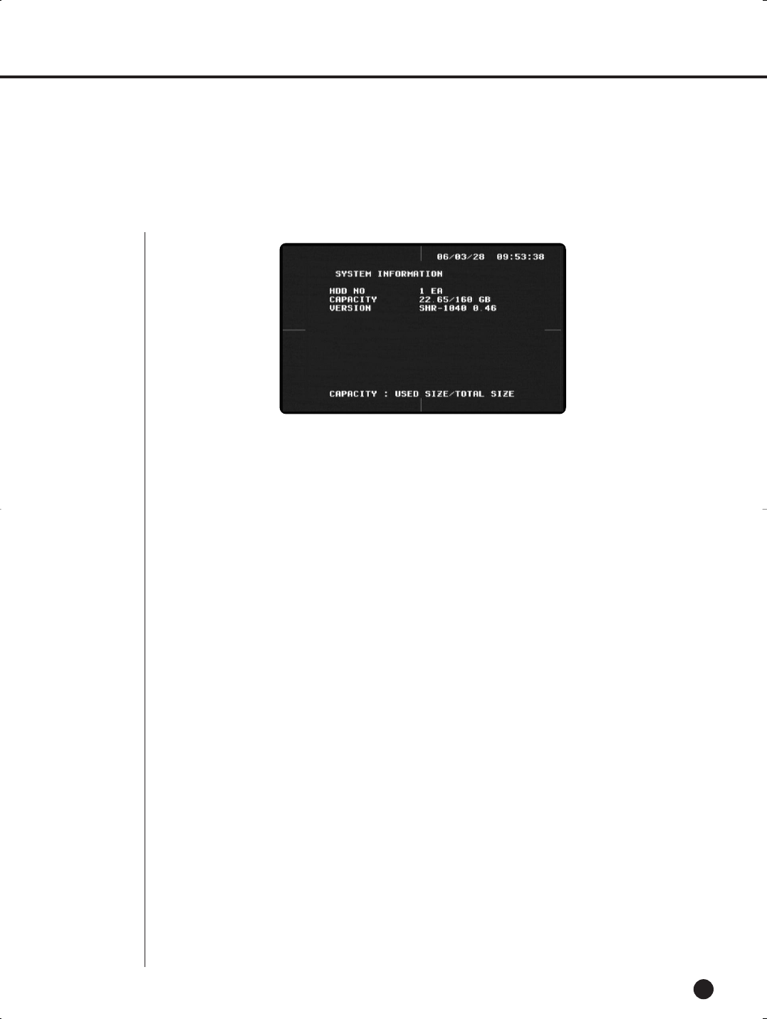
10
System Information
(1) HDD NO
Displays HDD quantity that is installed on the system.
(2) CAPACITY
Displays the HDD capacity of the System.
[Remaining Capacity/Entire HDD Capacity]
(3) VERSION
Displays the version of the System.
SHR-1040/SHR-1040K-ENG 2006.4.4 11:12 AM ˘ ` 5-14

English
Chapter 7.
Recording
7
SHR-1040/SHR-1040K-ENG 2006.4.4 11:12 AM ˘`7
SHR-1040/1040K USER’S MANUAL
English
7-1
1
Basic Recording
2
Timer Recording
Press the Record button ( ● ) to record live video. The Rec LED is lit, and the ( ●) mark
appears on the screen. The HDD LED blinks, indicating that data is being recorded to the HDD.
-You can set the time and date of recording. From the menu list, enter the day of the week
(Mon. to Sun. or daily) and the time in the TIME RECORD MODE.
-Recording starts and proceeds on the scheduled time and date for the specified hours.
SHR-1040/1040K USER’S MANUAL
Note
Note
You cannot record previously recorded data now being played back. To record the data, you
must stop the playback of the data first.
Note
Note
Enter the Time Record Mode from the Menu screen, and set On/Off before setting the time
and date of recording. You can also set the number of fields to be recorded per minute.
SHR-1040/SHR-1040K-ENG 2006.4.4 11:12 AM ˘ ` 6-1
EnglishEnglishEnglish
7-2
Start recording when a motion is detected in the channel and area set by the Alarm/Motion
Record Setup menu. When the motion record begins, the M mark is displayed next to the
channel, indicating recording is on.
The Alarm In connector is located in the external in/out port of on the back panel of the
system. You can connect the connector with an external device.
Then, set the EVENT RECORD ENABLE ‘On’ in the EVENT RECORD SETUP menu to
start recording when an alarm occurs. When recording starts, the following screen appears.
3
Motion Recording
4
Alarm Recording
Note
Note
- To enable the motion detection, you have to set an area for each channel. MOTION DETEC-
TION operates only if there is a motion detected in the area of the channel you have selected.
Caution
Caution
Recording stops when the connection with input video signals is interrupted during recording.
The system starts recording again when connection to input signals is restored. The system
does not start recording when video signals are not connected to the Video In end.
SHR-1040/SHR-1040K-ENG 2006.4.4 11:12 AM ˘ ` 6-2
SHR-1040/1040K USER’S MANUAL
English
5
Stop Recording
7-3
●Click the Stop button to stop data recording.
The REC mark disappears as follows, and recording is stopped.
To stop data recording, click the STOP button.
The REC mark disappears and the current recording stops as shown in the
picture. However, if RECORD LOCK is set to ON, you have to enter the password
to stop recording.
SHR-1040/SHR-1040K-ENG 2006.4.4 11:12 AM ˘ ` 6-3

Chapter 8.
Search & Playback
English
8
SHR-1040/SHR-1040K-ENG 2006.4.4 11:12 AM ˘`7
SHR-1040/1040K USER’S MANUAL
English
8-1
1
Search Menu
●Menu Operation
Move to the menu items by using the left/right and up/down buttons (œ,√,…,†). The
selected item is highlighted and displayed with the cursor. Press the Select button to
enter the sub menu. In the sub menu, you can enter conditions for data search or
select from the list of the recorded data to play back data you want.
●Enter Search Conditions & Select from the List
Time & Data Search Enter the conditions for data search in the menu, and press the
select button. You can either enter the conditions or select from the list as in the
general menu.
●Move Up To Menu or End Search/Playback
To move up from the sub menu or end search, press the Menu button. To end play-
back after selecting data search, press the Search Key and exit through the Live
screen.
SHR-1040/1040K USER’S MANUAL
W
Warning
arning
The current time and date is displayed in the Time and Date section of the Time/Date Menu.
Search recorded data by entering the time and date you want.
The list is not available in the Event Search menu at default, since data is not stored on the
HDD.
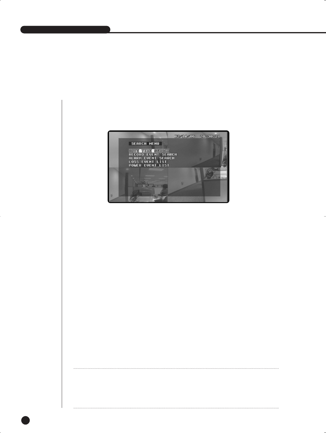
- DATE & TIME SEARCH : Search recorded data based on the time and date.
- RECORD EVENT SEARCH : Searches for all data recorded in Normal Record or Timer
Record.
- ALARM EVENT SEARCH : Search all the data recorded in the Alarm/Motion mode.
- LOSS EVENT LIST : Display information on the channel and time at the time of Video Loss.
- POWER EVENT LIST : Display information on On/Off time of power.
●Search Menu
Press the Search button in Live mode to search recorded data.
The following screen appears.
Search is not enabled during recording. Stop recording to start search.
SHR-1040/SHR-1040K-ENG 2006.4.4 11:12 AM ˘ ` 7-1
EnglishEnglishEnglish
2
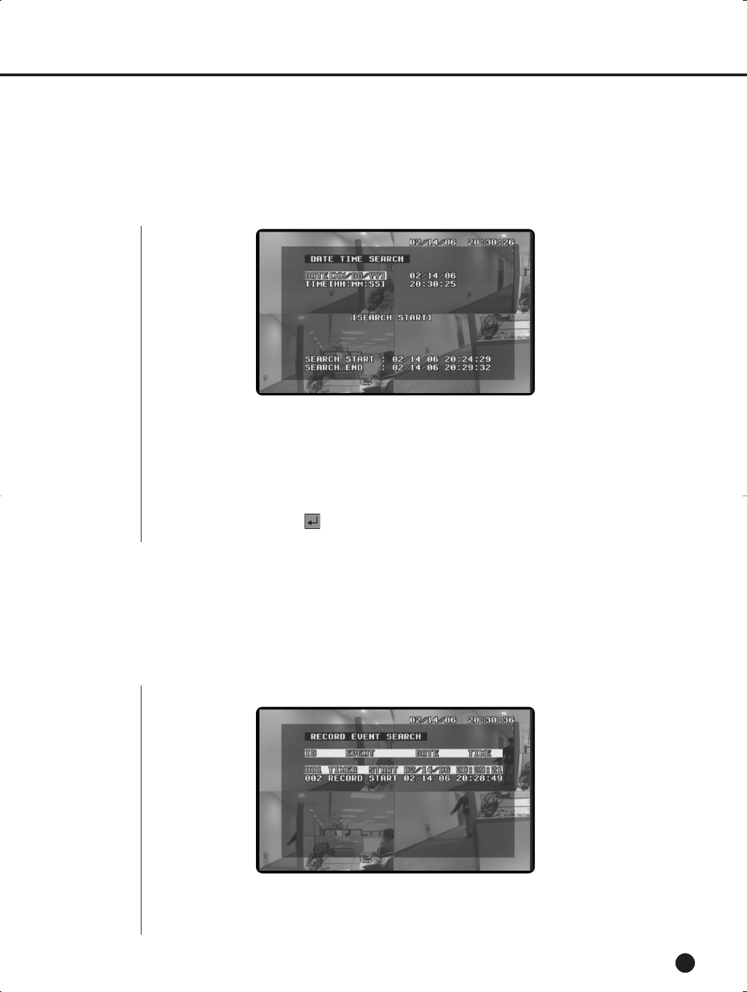
Date Time Search
8-2
●Displays the list of the data recorded in NORMAL RECORD or TIMER RECORD out of all
data on the HDD.
Select from the Record Event List by using up/down left/right buttons (…,†,œ,√). Press
the Search button after selecting from the Record Event List to start search.
●The following screen appears when selecting the Record Event Search after pressing
the Search button.
(1) DATE[YY/MM/DD]
Set the date (year/month/day) you want to search.
(2) TIME[HH:MM:SS]
Set the time you want to search.
(3) SEARCH START
Enter the year/month/day/hour/minute/second you want to search.
Press the Enter button ( ) to search the time and date.
3
Record Event Search
SHR-1040/SHR-1040K-ENG 2006.4.4 11:12 AM ˘ ` 7-2
SHR-1040/1040K USER’S MANUAL
English
8-3
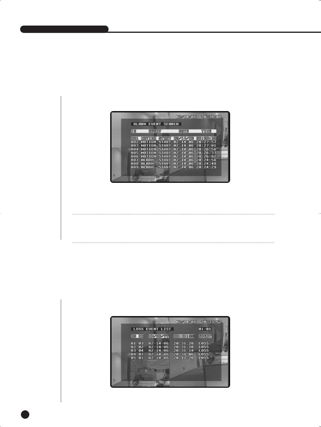
●Displays the list of the data recorded in ALARM or MOTION RECORD out of all data on the
HDD.
Select from the Record Event List by using up/down left/right buttons (…,†,œ,√). Press
the Search button after selecting from the Alarm Event List to start search.
●The following screen appears when selecting the Alarm Event Search after pressing
the Search button.
4
Alarm Event Search
●You can view the list on the following page by using the up/down/left/right buttons
(…,†,œ,√).
●Display the channel and the time and data at a time of Video Loss.
5
Loss Event List
Note
Note
Enter the Time Record Mode from the Menu screen, and set On/Off before setting the time
and date of recording. You can also set the number of fields to be recorded per minute.
SHR-1040/SHR-1040K-ENG 2006.4.4 11:12 AM ˘ ` 7-3
EnglishEnglishEnglish
8-4
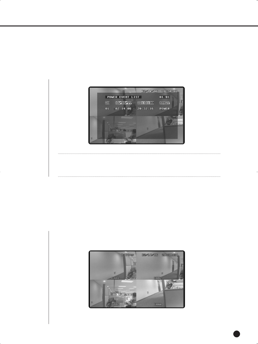
●You can view the list on the following page by using the up/down/left/right buttons (…,†,œ,√).
●Display the list of the time and date record of Power On/Off.
6
Power Event List
●The ‘No Data’ message is displayed when there is no recorded data.
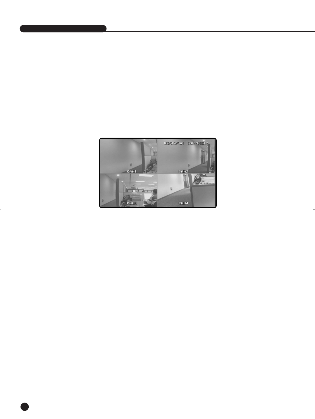
●Press the Play/Still Button to play back the recorded data on the HDD.
The following screen appears and playback starts.
You cannot play back data during recording. You must stop recording and play back
data in Live mode.
7
Basic Playback
Note
Note
Enter the Time Record Mode from the Menu screen, and set On/Off before setting the time
and date of recording. You can also set the number of fields to be recorded per minute.
SHR-1040/SHR-1040K-ENG 2006.4.4 11:12 AM ˘ ` 7-4
SHR-1040/1040K USER’S MANUAL
English
8-5
Note
Note
Enter the Timer Record Mode from the Menu screen, and set On/Off before setting the time
and date of recording. You can also set the number of fields to be recorded per minute.
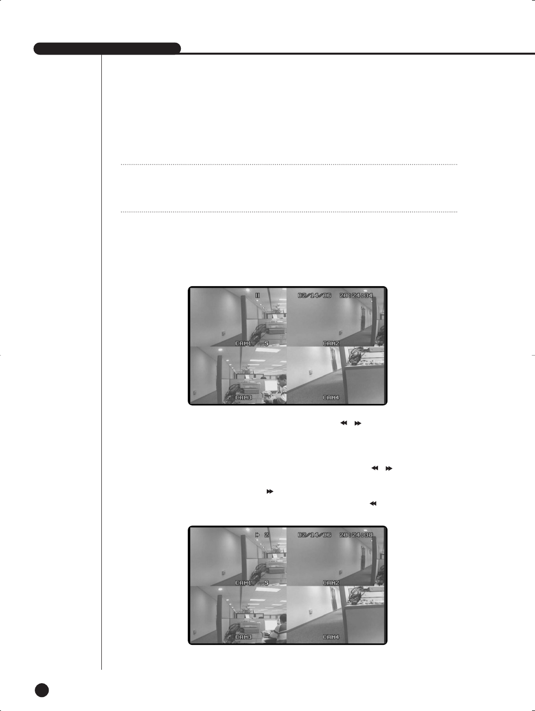
●When the system reaches the end of the HDD during playback or the end of the current data, the system will start
playing back from the beginning of the first data on the HDD.
●If you press FAST FORWARD or FAST REWIND button (, )during playback, the
system plays the data fast forward or fast in reverse, respectively.
FAST FORWARD is available in 2X, 4X, 8X, 16X, 32X, and 64X and FAST REWIND,
-2X, -4X, -8X, -16X, -32X, and -64X.
●When pressing the FAST FORWARD or FAST REWIND button (, )during Still, the
system plays back data cut-by-cut in reverse and forward.
●If you press the FAST FORWARD ()
button during normal playback, the playback
speed increases forward. While you press the FAST REWIND ( ) button, the play-
back speed increases in reverse.
●To restart playback, press the Play/Still button.
●When pressing the Play/Still button during playback, the following screen appears and
the screen is in Still mode.
SHR-1040/SHR-1040K-ENG 2006.4.4 11:12 AM ˘ ` 7-5

Chapter 9.
Appendix
9
English
SHR-1040/SHR-1040K-ENG 2006.4.4 11:12 AM ˘ ` 7-6
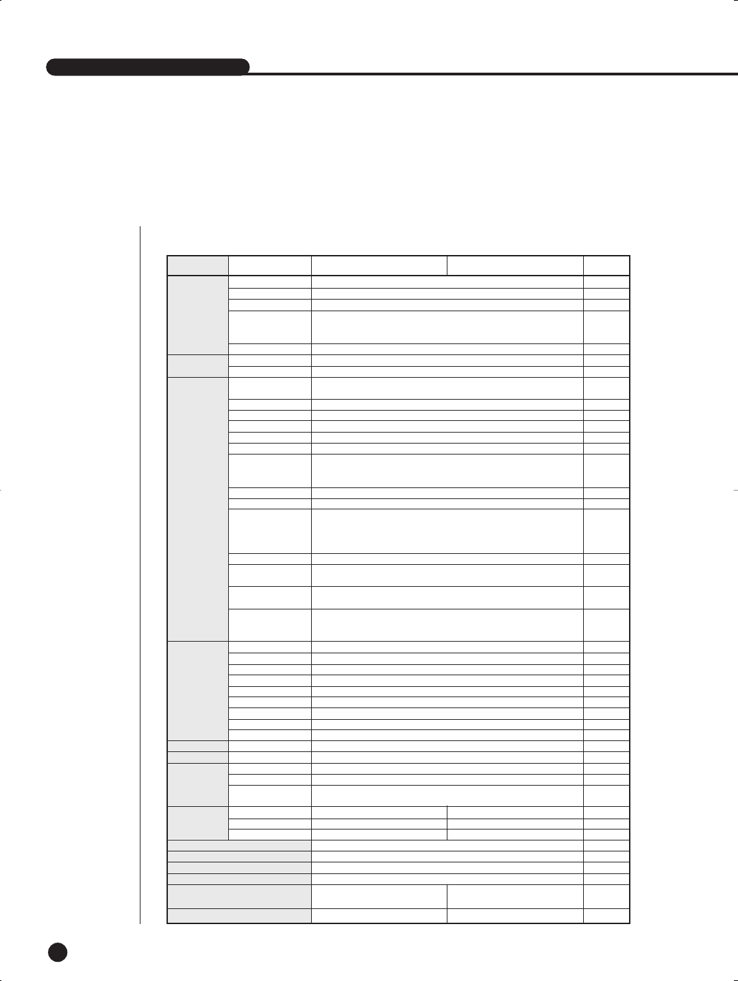
NTSC
4 BNC, 4CH(RJ-11 DIY Camera)
2 BNC, 2RCA, 1VGA
1ch - FullScreen,
Quad, Sequence,
Freeze, Zoom, PIP
720*480
4CH(RCA), 4CH(RJ-11 DIY Camera)
2 CH(RCA)
1CH mode : 30IPS
4CH mode : 120IPS
MPEG4
G.723
Simplex
1CH Mode, 4CH Mode
4 CH Realtime
Time Lapse,
Event(Alarm,Motion),
Schedule (Date/Time)
-64, -32, -16, -8,-4, -2, 1, 2, 4, 8, 16, 32, 64
Forward/Reverse
200hours(4CH Real time)
500hours(1CH Real time)
Time Lapse Mode :
Max 15000hours
704*240
High : 14KB, Normal : 6KB,
Low : 3KB
Record Event, Alarm/Motion Event,
Power, Loss CH
Recod Event Search,
Alarm/Normal Event Search,
Date/Time Search
1(Terminal Jack), 4(RJ-11 DIY Camera)
1(Terminal Jack)
1(Terminal Jack)
OFF, 1sec, 2sec, 3sec, 4sec, 5sec
5sec ~ 59sec, 1M,2M ~ 30M
O
9 area / CH
High, Middle, Low
on/off
O
160G(MAX HDD SIZE : 250GB *2)
AC100 ~ 240, 2A, 50/60Hz
DC 12V, 4A
RJ-11 Jack, DC 12V,
4W *4
1EA 1EA
X 2EA
X 2EA
32˚F ~ 104˚F
-4˚F ~ 140˚F
20% ~ 85% RH
20% ~ 85% RH
6 lbs, (Packing) 9.26 lbs 6 lbs, (Packing) 17.42 lbs
SHR-1040/1040K USER’S MANUAL
English
1
Product Specification
9-1
SHR-1040/1040K USER’S MANUAL
1) SHR-1040, SHR-1040K
Signal Format
Video Input
Video output
Display Resolution
Audio Input
Audio Output
Video CODEC
Audio CODEC
Simplex/Duplex
Video REC CH Number
Display Speed
Play Speed
Frame Advance
Video Record Resolution
Input
Output
Alarm Reset
Pre Alarm
Duration
Buzzer
Motion Det.
Motion Detection Level
Password
Remocon
HDD
AC Input
Adapter
SHR-1040
SOC-C120
SOC-N120
Video
Audio
REC/Play
/Searching
Alarm/Motion
Remocon
Storage
Power
SET
Operation Temp.
Preservation Temp.
Operation Humidity
Preservation Humidity
Size (INCH)
Weight (LBS)
default 1EA
Block
Function SHR-1040 SHR-1040K(DIY Kit) etc
Display Mode
Video REC/PB Speed
REC Mode
Recording Capability
Time
REC File Size
Event List
Search Mode
Camera Power Output
8.46(W) X 3.46(H) X 13.27(D),
(Packing) 17.95(W) X 7.20(H) X 13.30(D)
8.46(W) X 3.46(H) X 13.27(D)
(Packing) 17.95(W) X 11.5(H) X 13.3(D)
SHR-1040/SHR-1040K-ENG 2006.4.4 11:12 AM ˘ ` 8-1

EnglishEnglishEnglish
9-2
English
9-3
Model Name
Broadcasting System
Imaging Device
Effective Pixels S
Synchronization
Resolution
Signal Output
S/N Ratio
Minimum Scene Illumination
Gamma Correction
Lens
Auto Exposure
Audio
I/O Connectors
Operating Temperature
Power Source
Power Consumption
Dimensions
Weight
SOC-C120
NTSC STANDARD
1/4” SUPER HAD (Hole Accumulation Diode) IT CCD
510(H) x 492(V)
Internal
H :330 TV Lines, V: 350 TV Lines
VBS 1.0Vp-p(75ohms composite)
48 dB
2lux(F2.0, 50 IRE)
0.45
Focal Length (f) : 3.8 mm, F Number = 2.0
Electronic Shutter lris
-40dB Condenser Microphone Inclusion
Modular jack
+32 °F ~ +104 °F
DC 12V
Approx. 2W
2.25(W) x 1.86(H) x 3.95(L) inch
0.29 Ibs
2) SOC-C120 : Standard Camera
SHR-1040/SHR-1040K-ENG 2006.4.4 11:12 AM ˘ ` 8-2

SHR-1040/1040K USER’S MANUAL
English
9-3 9-4
Model Name SOC-N120
Product type IR LED Day &Night Vision Camera
Power source Voltage DC 12V from Equipment(DIY Monitor or DVR )
Brodcast System NTSC Standard Color Camera
Image Device 1/4 inch IT S-HAD CCD
Effective Pixel 510(H)x492(V)
Scanning Method 525lines 2 : 1 Interlace
Horizontal : 15,734Hz
Vertical : 60Hz
Weather Resist Grade IP43
Synchronization Method INT
Resolution 330TV lines
S/N Ratio 48dB
Light Condition Light sensor Auto Switching IR LED Control 10pcs
Normal : 2 Lux
Night mode : IR LED ON
Color Temperature ATW
Elctronic shutter ELC
Signal Output Composite Video out 1.0Vp-p 75 ohms RJ11
Focal length : 3.8mm
Aperture(F) : F2.0
Operating Temperature -10°C~ +50°C
Operating Humidity ~90%
Physical Size 2.51(W) X 2.44(H) X 4.92(L)inch
Weight 0.33 lbs
3) SOC-N120 : Nightvision Camera
Line Frequency
Minimum scene Illumination
Lens
SHR-1040/SHR-1040K-ENG 2006.4.6 3:31 PM ˘ ` 8-3
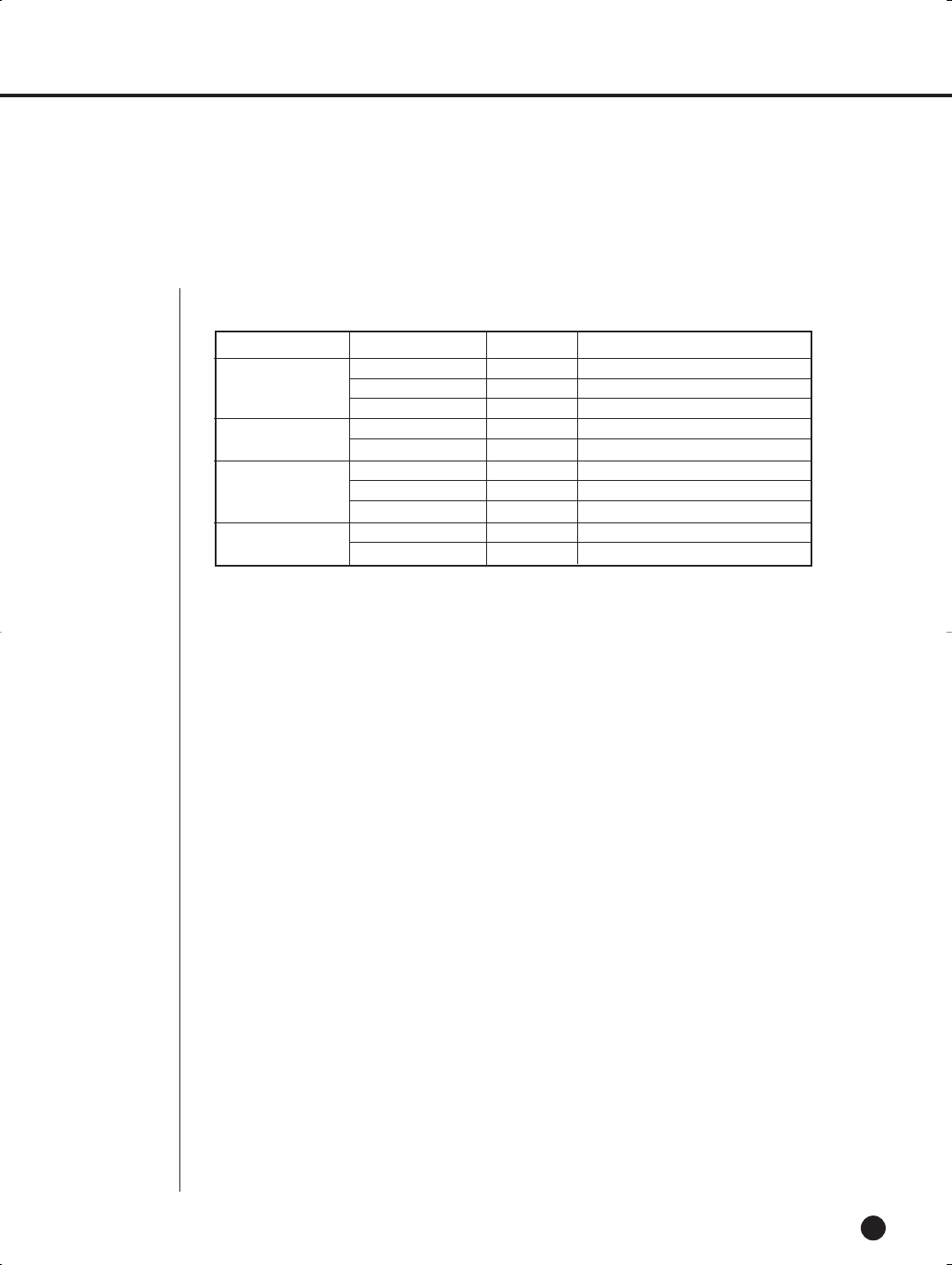
MAKER MODEL CAPACITY REMARK
SV0802N 80GB
SV1604E 160GB
SV2041N 200GB
WD1600JB 160GB
WD2500JB 250GB
6L160PO 160GB
6L200PO 200GB
6L250RO 250GB
ST3160212ACE 160GB Attached model in shipment
ST3250823A 250GB
9-4
English
2
Recommended HDD List
SAMSUNG
WesterN Digital
Maxtor
Seagate
SHR-1040/SHR-1040K-ENG 2006.4.4 11:12 AM ˘ ` 8-4
SHR-1040/1040K USER’S MANUAL
9-5
English
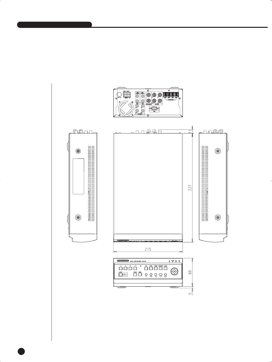
3
Outline Drawing
SHR-1040/SHR-1040K-ENG 2006.4.4 11:12 AM ˘ ` 8-5
