Samsung Sph 20W P Users Manual
SPH-20WP to the manual 60611cc0-cb6a-4754-8ab1-b4e363184c80
2015-01-23
: Samsung Samsung-Sph-20W-P-Users-Manual-282847 samsung-sph-20w-p-users-manual-282847 samsung pdf
Open the PDF directly: View PDF ![]() .
.
Page Count: 18
SAMSUNG CCTV SYSTEMS
SPEED DOME OUTDOOR HOUSINGS
INSTRUCTION MANUAL
SPH-20W/P
SWH-20W/P
SAMSUNG TECHWIN CO., LTD
OPTICS & DIGITAL IMAGING DIV. 145-3, SANGDAEWON 1-DONG, JUNGWON-GU,SUNGNAM, KYUNGKI-DO, KOREA
462-703
TEL : 82 -31-740 - 8137~41 FAX: 82 -31-740 - 8145
SAMSUNG OPTO-ELECTRONICS AMERICA, INC.
40 SEAVIEW DIRVE, SECAUCUS N.J 07094, U.S.A.
TEL : (201) 902-0347 FAX : (201) 902-0429
www.samsungcctv.com
www.samsungtechwin.com
삼성테크윈주식회사

1
OUTDOOR DOME HOUSINGS
Contents
SAFETY PRECAUTIONS ....................................................................... 2
UNPACKING ........................................................................................... 2
IMPORTANT SAFEGUARDS .................................................................. 3
FEATURE ............................................................................................... 4
ELECTRICAL SPECIFICATIONS ............................................................ 5
GENERAL INSTRUCTIONS.................................................................... 5
INSTALLING QUICK RELEASE BRACKET AND UNITIZED
CAMERA ASSEMBLY ............................................................................ 6
INSTALLING THE HOUSING ASSEMBLY .............................................. 7
FOR WALL MOUNT VERSIONS .......................................................... 7
FOR PENDANT MOUNT VERSIONS .................................................. 8
WIRING COLOR CODE .......................................................................... 8
EXPLODED VIEWS OF HOUSING ........................................................ 10
MOUNTING TEMPLATE ......................................................................... 13
DIMENSIONS ......................................................................................... 14
WARRANTY CARD ................................................................................ 15
Outdoor Housing for Speed Dome Camera (SPD-1600, SPD-2500)
Wall Mount Type.
SPH-20W
Outdoor Housing for Speed Dome Camera (SPD-1600, SPD-2500)
Pendant Mount Type.
SPH-20P
Outdoor Housing for Web Speed Dome Camera (SWC-160, SWC-250)
Wall Mount Type.
SWH-20W
Outdoor Housing for Web Speed Dome Camera (SWC-160, SWC-250)
Pendant Mount Type.
SWH-20P
EXPLANATION OF MODEL NAME
2
OUTDOOR DOME HOUSINGS
3
OUTDOOR DOME HOUSINGS
SAFETY PRECAUTIONS
UNPACKING
RISK OF ELECTRIC SHOCK
DO NOT OPEN
CAUTION
CAUTION :
TO REDUCE THE RISK OF ELECTRIC SHOCK, DO NOT
REMOVE COVER (OR BACK), NO USER SERVICEABLE
PARTS INSIDE. REFER SERVICING TO QUALIFIED
SERVICE PERSONNEL.
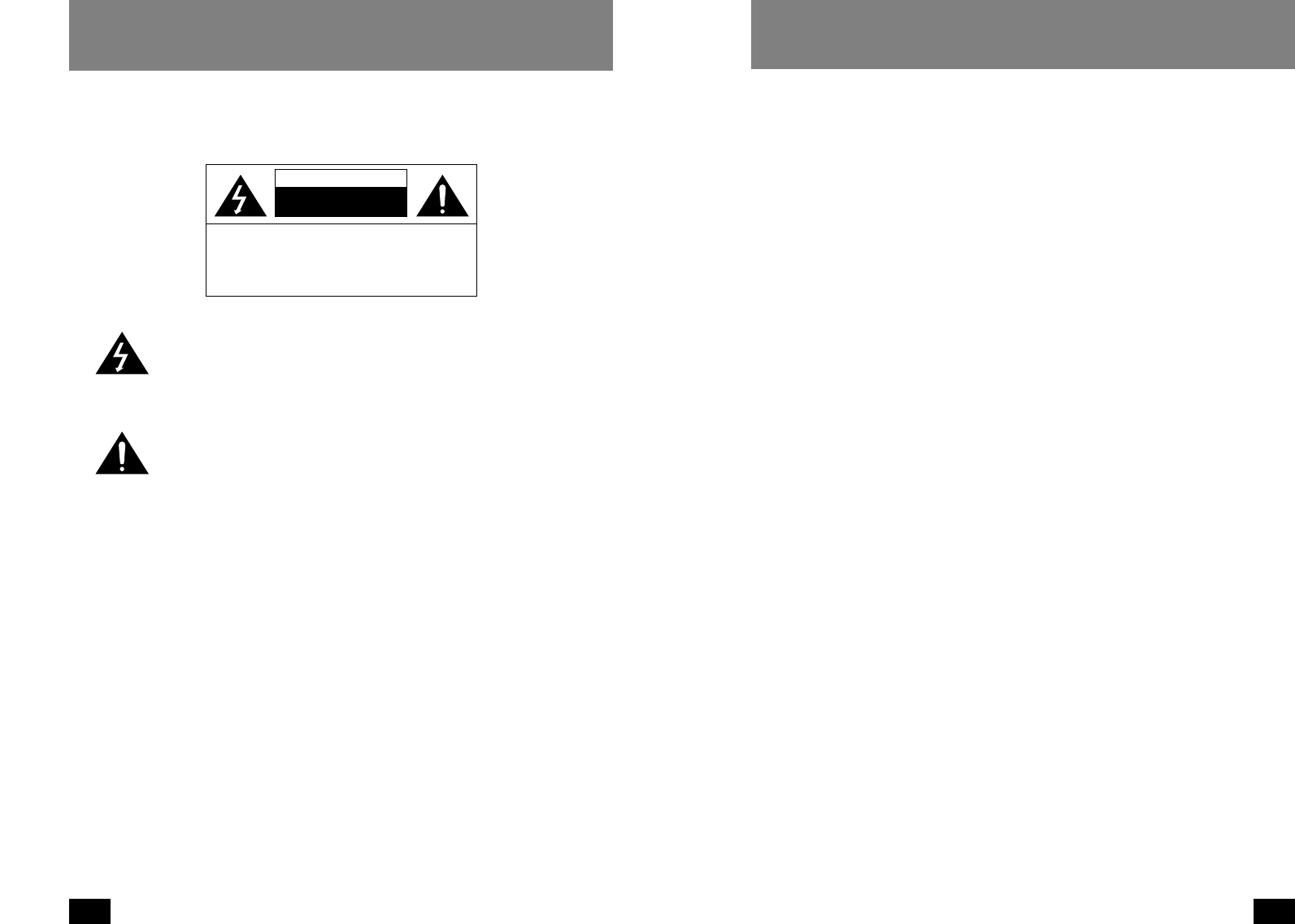
The lightning flash with an arrowhead symbol, within an equilateral triangle,
is intended to alert the user to the presence of non-insulated "dangerous
voltage" within the product's enclosure that may be of sufficient magnitude
to constitute a risk of electric shock to persons.
The exclamation point within an equilateral triangle is intended to alert the
user to presence of important operating and maintenance (servicing)
instructions in the literature accompanying the appliance.
Unpack carefully. Electronic components can be damaged if improperly handled
or dropped. If an item appears to have been damaged in shipment, replace it
properly in its carton and notify the shipper.
Be sure to save:
1. The shipping carton and packaging material. They are the safest material in
which to make future shipments of the equipment.
2. These Installation and Operating Instructions.
IMPORTANT SAFEGUARDS
1. Read Instructions - All the safety and operating instructions should be read
before the unit is operated.
2. Retain Instructions - The safety and operating instructions should be
retained for future reference.
3. Heed Warnings - All warnings on the unit and in the operating instructions
should be adhered to.
4. Follow Instructions - All operating and user instructions should be followed.
5. Electrical Connections - Only a qualified electrician should make electrical
connections.
6. Attachments - Do not use attachments not recommended by the product
manufacturer as they may cause hazards.
7. Cable Runs - All cable runs must be within permissible distance.
8. Mounting - This unit must be properly and securely mounted to a supporting
structure capable of sustaining the weight of the unit. Accordingly:
a. The installation should be made by a qualified installer.
b. The installation should be in compliance with local codes.
c. Care should be exercised to select suitable hardware to install the unit,
taking into account both the composition of the mounting surface and the
weight of the unit. Be sure to periodically examine the unit and the
supporting structure to make sure that the integrity of the installation is
intact. Failure to comply with the foregoing could result in the unit
separating from the support structure and falling, with resultant damages or
injury to anyone or anything struck by the falling unit.
4
OUTDOOR DOME HOUSINGS
5
OUTDOOR DOME HOUSINGS
Durable engineered plastic top, 94VO, outdoor and
pressurized models are UV protected.
Accepts many manufacturers’ unitized camera systems.
Accepts single fixed camera.
Available in wall or pendant mount.
Temperature rating -50 F standard.
DESCRIPTION:
All plastic components are designed to be UV stable; the housing top is
rated at 94VO. The wall mountunit measures 11.5" (w) x12.9 (h) x 16"
(d), with a weight of 7 lbs.; measurements for the pendant mount unit
are 11.5" (w) x 12.9" (h) x 11.5" (d), 7 lbs. Flying leads are provided for
all incoming power, control, and video connections. The leads are
supplied with a standard BNC and screw down connectors. A 22 watt
heater and a circulation blower are also provided. To service, remove
the lower dome and ring assembly.
FEATURE ELECTRICAL SPECIFICATIONS:
Input power : Housing & Camera - 12 VDC
22 watts at 12 VDC
Heater : 20 watts
Blower : 2 watts
GENERAL INSTRUCTIONS:
Tools Required: .100" Flat Head Screwdriver
Phillips Head Screwdriver
PREPARING PENDANT MOUNT BRACKET
(For wall mount see page 7)
1. Carefully remove the housing from the packaging material.
Check to be sure all parts are present.
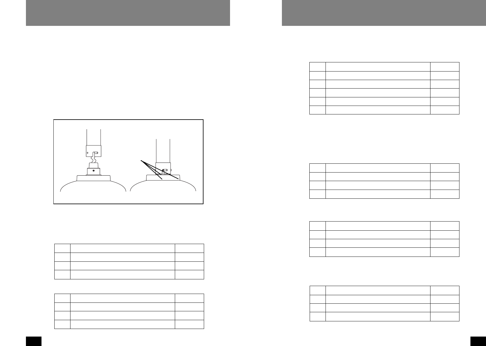
2. This unit includes a 1 1/2" NPT housing coupling that can be used with a
standard 1 1/2" NPT pipe.
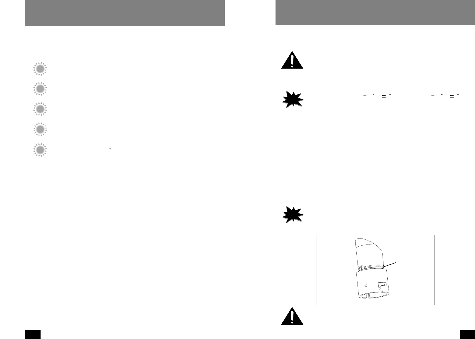
3. Attach the housing coupling to the bracket or pendant pipe (Figure 1).
NOTE
Notes
·This unit can be used with brackets designed with
1 1/2" male pipe
threads that don’t be supplied.
·Pipe threads should be clean and rust free. Use a sealer (such as
Teflon™ tape or silicone sealer) on the threads.
NOTE
Notes
·The heater activates at 40 F ( 8F), deactivates at 60 F ( 8F).
·The blower always activates.
Figure 1
Add thread
sealing tape
Be sure the bracket is properly and securely mounted to a supporting
structure capable of rigidly holding the weight of the entire unit.
6
OUTDOOR DOME HOUSINGS
7
OUTDOOR DOME HOUSINGS
8-32 Security
fastener
Place for
connectors
Figure 3
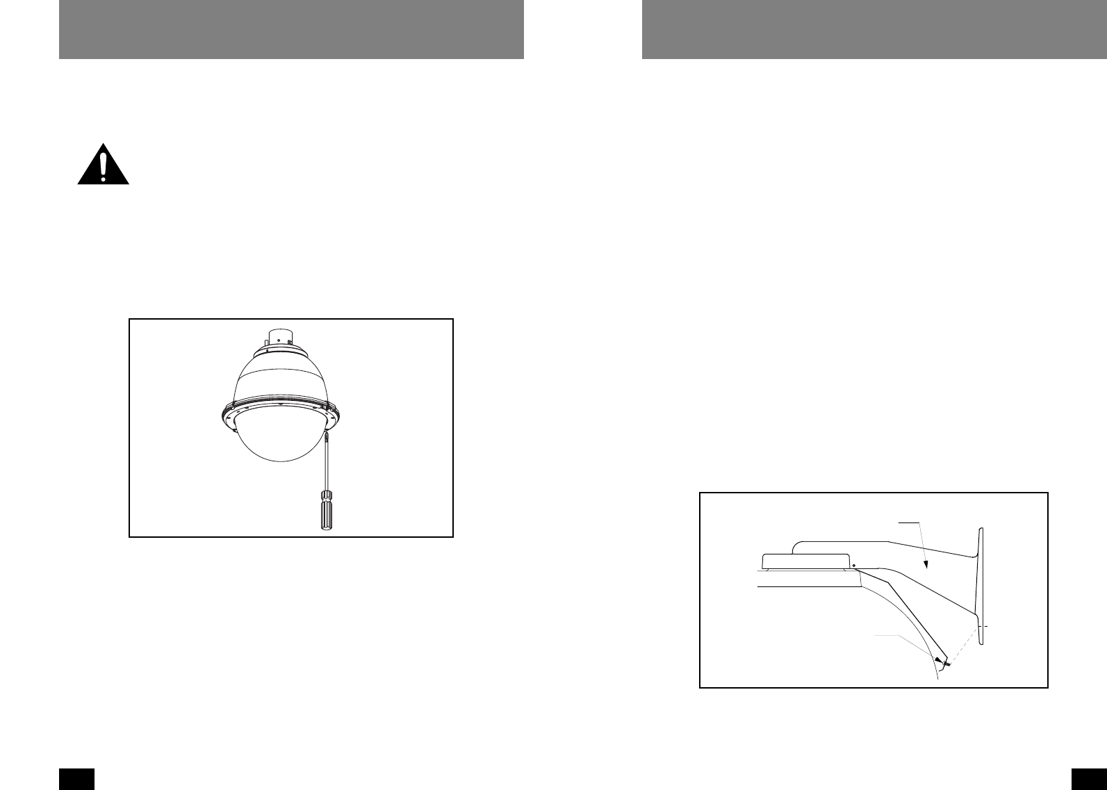
1. Open the housing by loosening the (3) captive screws located on the housing
ring next to the lower clear dome. Be careful not to back these all the way out.
Twist the dome and ring assembly slightly in a counterclockwise motion to
remove (Figure 2).
2. Install the pan/tilt unit quick-release bracket. It is recom- mended that this be
done before installing the housing.
3. It is recommended that the unitized camera be installed at this time. Connect
to the quick-release bracket and secure per manufacturer directions.
4. Clean the inside of the dome, with the text-wipe provided. Reattach the
housing dome and secure the (3) captive screws.
Do not overtighten the screws. Tighten only to the point at which the gap
between the ring and the housing top closes.
Figure 2
Loosen screws only,
do not remove
Remove dome by
twisting counter-
clockwise
INSTALLING THE HOUSING ASSEMBLY
FOR WALL MOUNT VERSIONS
1. A wall mount bracket comes standard with this unit, and a template is
included to use as a guide for mounting the bracket to a wall. Choose the
desired location for installation and mark the drill holes using the template.
Screw (2) bolts (not provided) about 3/4 of the way into the (2) top holes. Run
approximately 8" of wiring out of the wall.
2. Open the access door on the bottom of the wall mount by loosening the screw
nearest the mounting plate (Figure 3).
3. Slip the housing onto the top (2) bolts and pull the wires from the wall through
the rectangular hole in the wall mount bracket. Screw bolts and washers
through the bottom (2) holes and secure. Remove the top (2) bolts, add
washers, and reattach, tightening completely.
4. Attach the wires from the wall to the connector provided, using the wiring
color code chart as a guide.
5. Once all wiring connections are made, place the wires inside the wall mount
bracket and close the access door. Secure with the screw removed earlier.
6. Clean the outside of the dome with the text wipe provided.
It is recommended that this be done before installing the housing.
INSTALLING QUICK RELEASE BRACKET AND
UNITIZED CAMERA ASSEMBLY
9
OUTDOOR DOME HOUSINGS
8
OUTDOOR DOME HOUSINGS
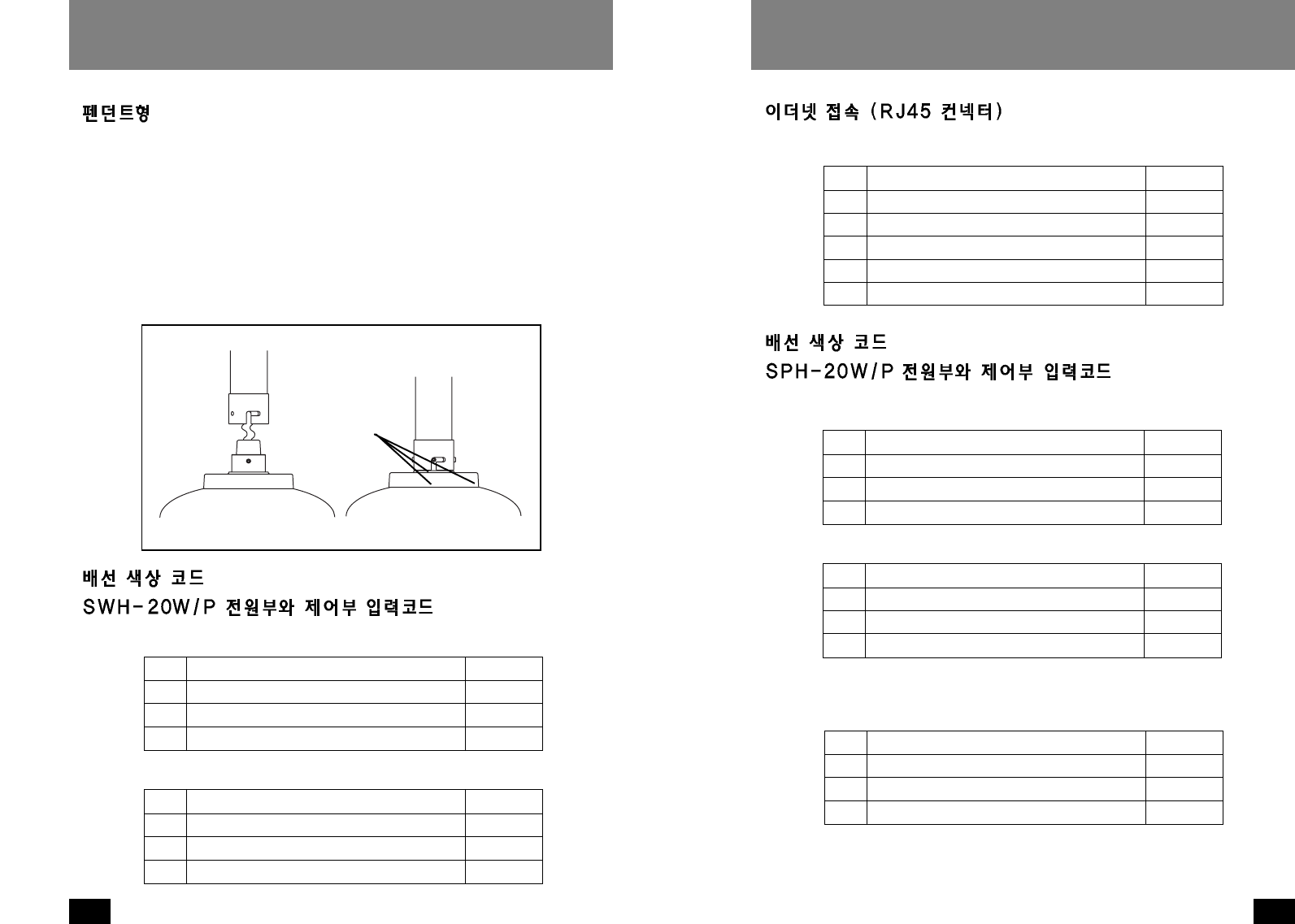
ETHERNET CONECTION (RJ45 CONNECTOR)
WIRING COLOR CODE
POWER AND CONTROL INPUTS (SPH-20W/P)
10 RXD (RS232) Blue
11 TXD (RS232) Violet
12 S1 + Gray
13 S1 - Orange
14 S2 + Brown
15 S2 - Tan
RS232 & Digital Alarms
1 Accessory Power (24 VAC) Yellow
2 Accessory Power (24 VAC) Green
3N/A
4N/A
Housing (Power 24 VAC)
1 Camera Power (+12 VDC) Red
2 Camera Power (Ground) Black
3 SYNC (Camera Power) White
4 N/A
Camera (Power 12 VDC)
RS-485
1 Data + Gray
2 Data - Violet
3 Ground Blue
4 N/A
FOR PENDANT MOUNT VERSIONS
1. Mount the housing assembly to the mounting bracket and housing coupling. A
safety cable is included with the housing to temporarily hold it while making
wiring connections. Loop the safety cable over one of the set screws on the
housing coupling and make the appropriate connections using the (2) screw-
down connectors supplied.
2. Undo the safety cable and twist the housing onto the housing coupling.
Secure all (3) setscrews provided on the housing coupling (Figure 4).
3. Clean the outside of the dome with the text wipe provided.
WIRING COLOR CODE
POWER AND CONTROL INPUTS (SWH-20W/P)
Figure 4
Twist and
Secure
1Accessory Power (+12 VDC) Red
2Accessory Power (Ground) Black
3N/A
4N/A
Housing (Power 12 VDC)
1 Camera Power (+12 VDC) Red
2 Camera Power (Ground) Black
3 SYNC (Camera Power) White
4 N/A
Camera (Power 12 VDC)
11
OUTDOOR DOME HOUSINGS
10
OUTDOOR DOME HOUSINGS
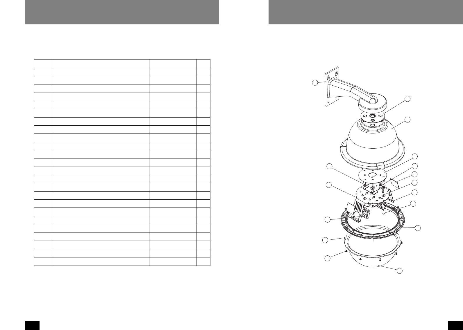
EXPLODED VIEWS OF HOUSING
Item No. Description Part No. Qty
1 Wall Mount Bracket Assembly 40-BRWM12 1
2 Housing Top 30-VL1697 1
3 Dome Support Ring 30-VL1695 1
4 20W, 12 VDC Heater 72-HT2170 1
n/s Clear Dome 20-DCFD8 1
5 Tinted Dome 20-DTFD8 1
n/s 9.25" O-ring 96-RSORG11 2
6 Plastic Ring Plugs 30-VL1696 6
7 1
8 Upper Housing Bracket 30-VL1744 1
9 Housing Gasket 96-PSGK05 3
10 Housing Fan 71-VLBL03 1
11 1
12 1/4 x 20 x .75" HH Bolts 90-BTHH27 4
12 1/4 Split Lock Washer 92-WSSL01 4
12 1/4 Flat Washer 92-WSFL01 4
13 10 x 32 x .75 Phil PH SS 90-BTRP28 3
15 Captive Screw 30-VL1749 3
n/s Captive Screw Spring 92-SPR01 3
n/s Captive Screw Retainer 94-FSRT04 3
16 Main Housing Bracket 30-VL1742 1
n/s Housing Ring 1" Lanyard Spring 92-SPR02 1
n/s Lanyard Spring Screws 90-BTPEM01 2
n/s Packet Assembly 40-PKFD8 1
16
15
7
13
12
11
10
9
8
7
6
5
4
3
2
1
Wall Mount Assembly (For SPH-20W, SWH-20W)
13
OUTDOOR DOME HOUSINGS
12
OUTDOOR DOME HOUSINGS
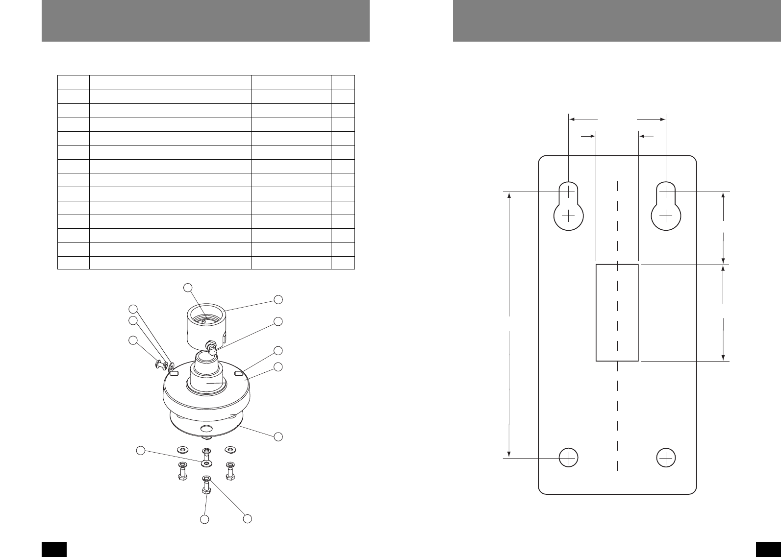
17 1/4 x 20 FH SS Bolt 90-BTSR01 1
18 Housing Pendent Bracket 30-VL926 1
19 1/4 Split Lock Washer 92-WSSL01 1
20 1/4 Flat Washer 92-WSFL01 1
21 Housing Gasket 96-PSGK05 1
22 1/4 x 20 x 1/2" Set Screw 90-BTSS05 2
23 1/4 Flat Washer 92-WSFL01 4
24 1/4 Split Lock Washer 92-WSSL01 4
25 1/4 x 20 x .75" HH Bolts 90-BTHH27 4
26 1 1/2" Housing Coupling 30-VL917 1
27 Upper Housing Gasket 96-PSGK04 1
28 1/4 x 20 x .375" HH Bolts 90-BTHH39 2
n/s 1/4 Flat Washer 92-WSFL01 2
n/s 1/4 Split Lock Washer 92-WSSL01 2
28
27
26
25 24
23
22
21
20
19
18
17
Pendant Assembly (For SPH-20P, SWH-20P)
2.000"
1.500"
0.875"
2.000"
5.500"
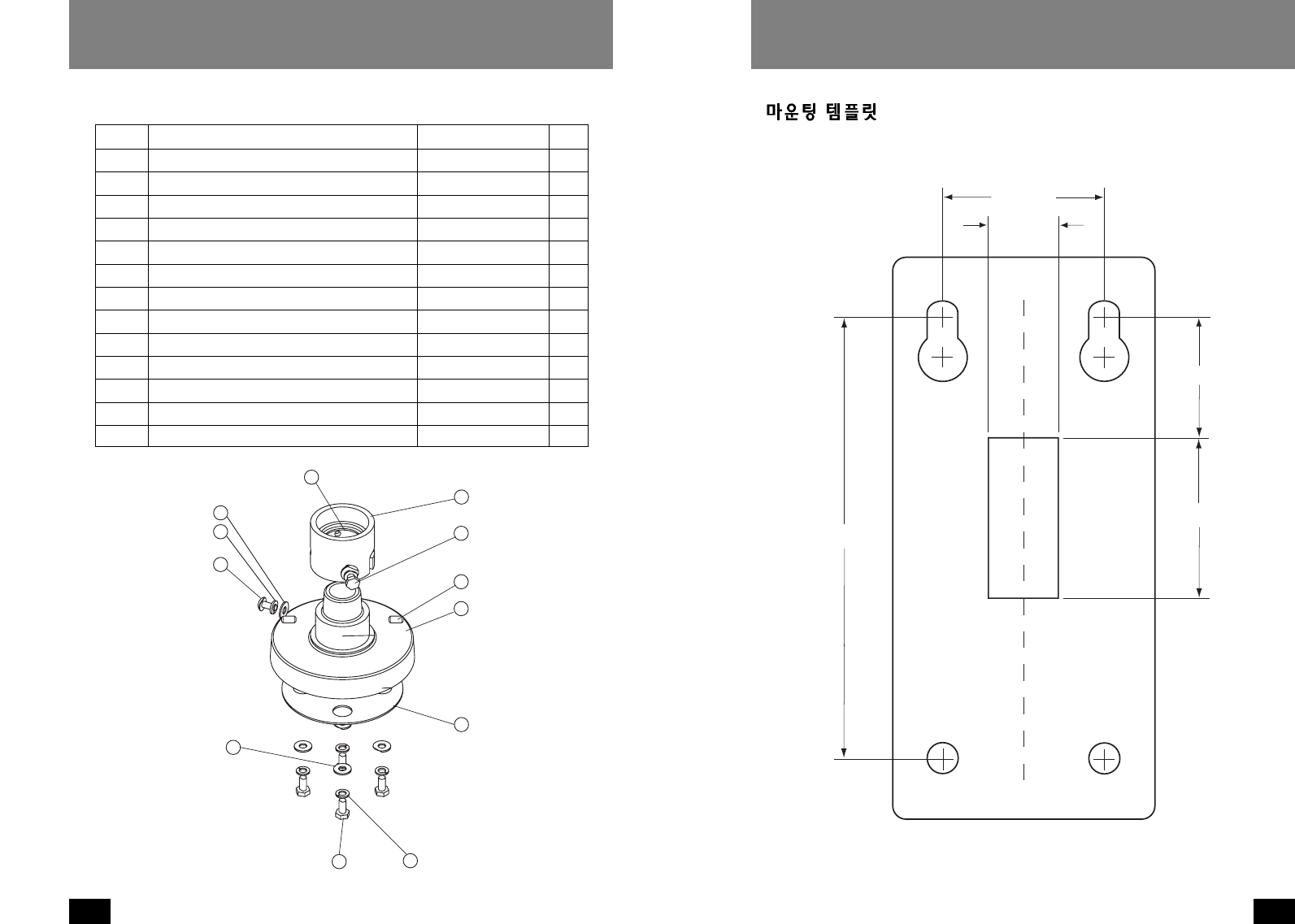
MOUNTING TEMPLATE
15
OUTDOOR DOME HOUSINGS
14
OUTDOOR DOME HOUSINGS
WARRANTY CARD
PRODUCT NAME
MODEL NAME
SERIAL NO.
WARRANTY PERIOD
NAME
PHONE
ADDRESS
NAME
PHONE
ADDRESS
PURCHASE
SPEED DOME HOUSING
1 YEAR
CUSTOMER
DEALER
DATE
PRICE
Thank you for purchasing this product.
This warranty is valid only on samsung techwin products by the instructions listed in the rear page within
warranty period except the periodic replace parts.
SAMSUNG TECHWIN CO., LTD
Head office :
SAMSUNG TECHWIN CO., LTD
145-3, Sangdaewon 1-Dong Jungwon-gu, Sungnam
Kyungki-do, Korea 462-703
TEL : 82-31-740-8137-8141 FAX : 82-31-740-8145
Branch office :
Samsung Opto Electronics America Inc.
40 Seaview Drive Secaucus, NJ USA 07094
TEL : 1-201-902-0347 FAX : 1-201-902-0429
Instructions
For Warranty
Before Calling Service
1. This product has been passed though a strict quality control and inspection.
2. Any trouble in functions and details of this product will be repaired or replaced free of charge.
(Although within 1 year, the items in this manual might be replaced at Buyer’s expense.)
3. This warranty is effective only in this country.
4. This card should be accompanied when repaired.
5. This warranty card should not be reissued, keep it in a safe place.
6. For repair, contact the authorized SAMSUNG products dealer from whom you purchased this
product.
1. Write purchased, let your authorized SAMSUNG PRODUCT dealer fill in the purchased
information.
Check the information on the warranty card and keep it in a safe place.
2. Our products are under manufacture’s liability insurance to ensure the quality assurance.
3. For the service items listed below, they are replace and repaired at Buyer’s expense (Repairing
cost + Parts prices + Traffic expenses) although within 1 year after purchasing time.
Chaneable service iems (The defects caused by followings will be repaired at Buyer’s expense.)
Careless handling Electricity misapplied Repaired by unauthorized personnel
Natural disaster (Fire, Sea Wind, Flood, etc) Repaired by user Consumable items
1. please read carefully “Note on use” and “Troubleshooting” on the operation manual.
2. If any more trouble, stop using and let me know by calling about the model name, symptom,
purchaser’s information.
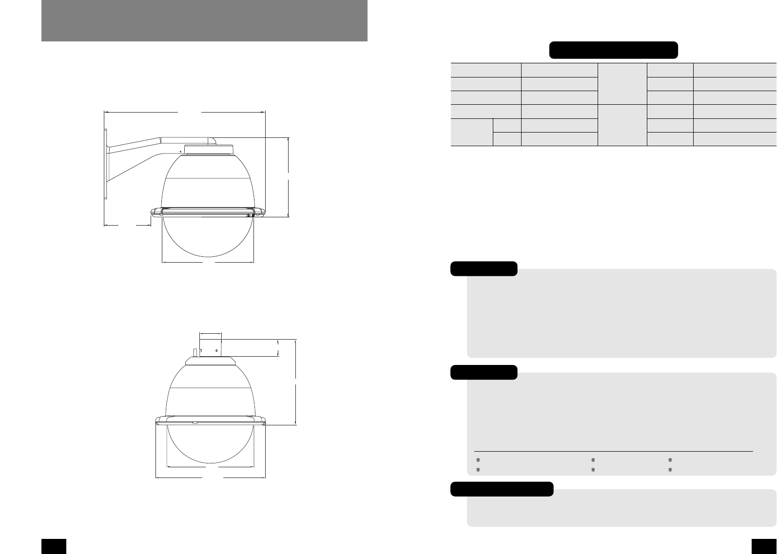
4.652"
16.069"
7.942"
8.8"
11.417"
2.250"
8.8"
8.893"
1.778"
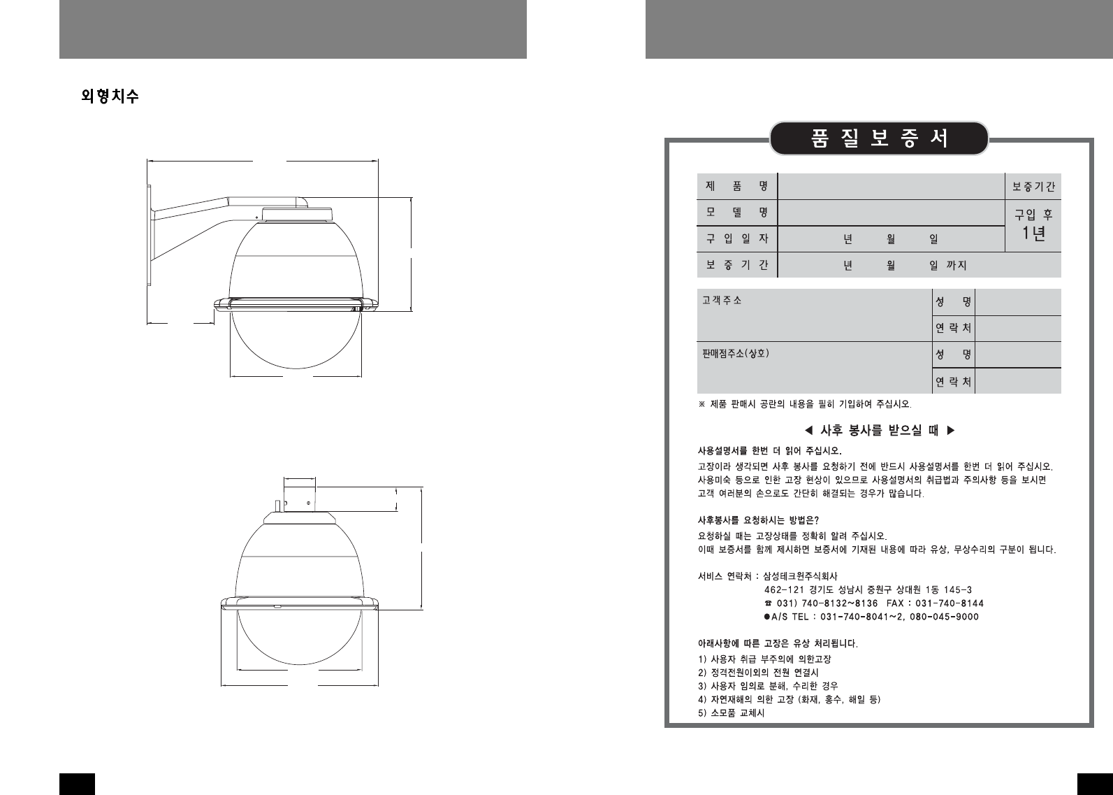
DIMENSIONS
Wall mount version
Pendant mount version
17
OUTDOOR DOME HOUSINGS
18
18
19
20
21
21
23
23
벽면 고정형
23
펜던트형
24
24
26
29
30
31
스피드돔 카메라 (SPD-1600, SPD-2500) 용실외하우징.
벽면고정형.
SPH-20W
스피드돔 카메라 (SPD-1600, SPD-2500) 용실외하우징.
펜던트형.
SPH-20P
웹스피드돔 카메라 (SWC-160, SWC-250) 용실외하우징.
벽면고정형.
SWH-20W
웹스피드돔 카메라 (SWC-160, SWC-250) 용실외하우징.
펜던트형.
SWH-20P
19
OUTDOOR DOME HOUSINGS
18
OUTDOOR DOME HOUSINGS
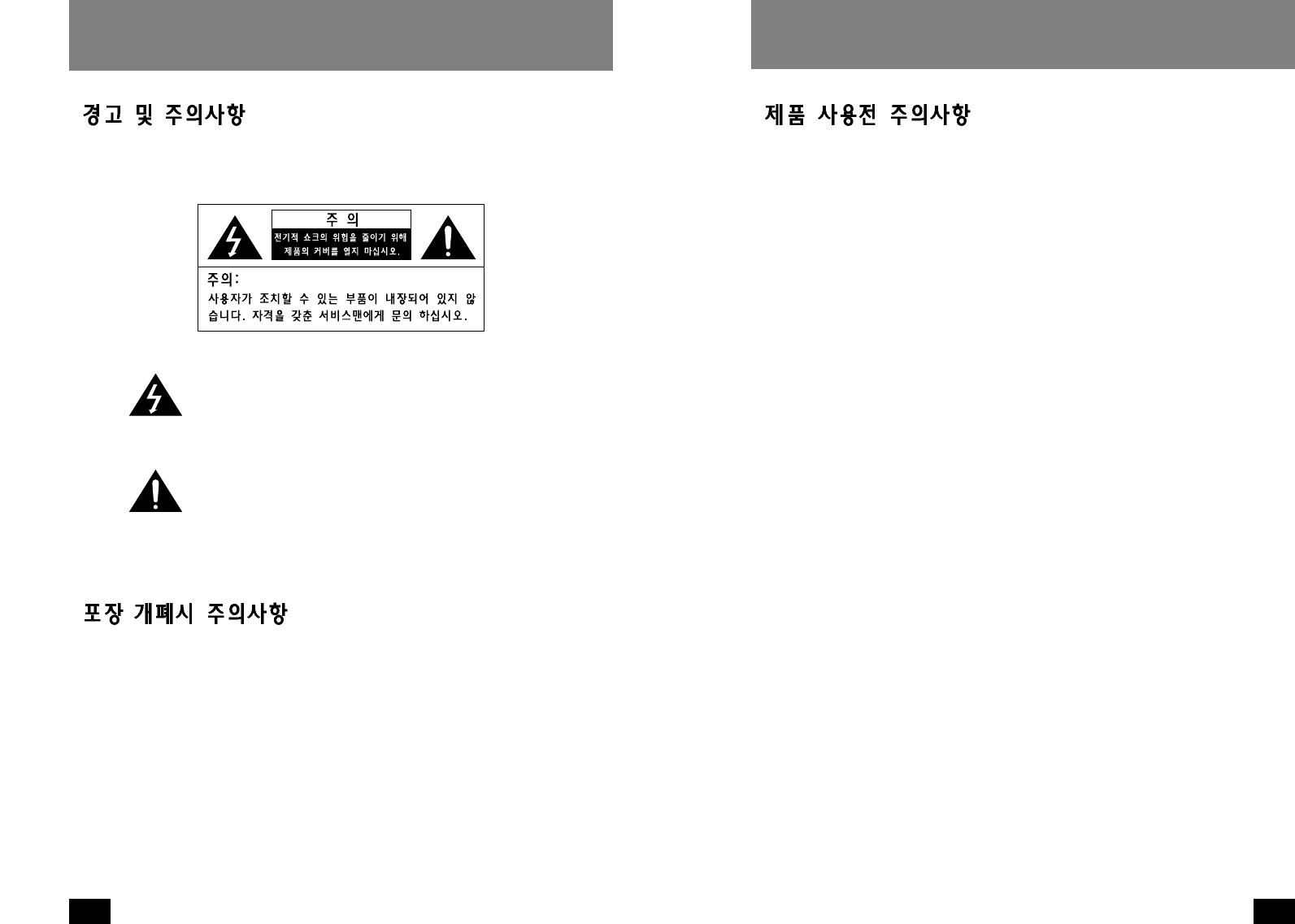
제품내에 사람에게 치명상을 줄수 있는 '위험전압'이 절연되
지않은상태로 존재함을 경고하는 것입니다.
중요한 동작사항 및 유지보수 사항에 대한 설명서가 제품과
함께 동봉되어 있으니 참고하라는 표시입니다.
조심해서 포장을 제거하십시오.부주의하게 취급하거나 떨어뜨리면 내부 전
자부품이 손상될 수 있습니다.운송중에 제품 손상이 발생하면 Box에 정위치
시키고 운송업자에게 통보하십시오.
사후보관 요망품
1.포장Box와 내부포장재. 나중에 제품을 운반할경우 가장 안전한 포장재로
활용할 수 있습니다.
2.설치 및 동작 설명서
제품을 올바르게 사용하여 위험이나 물적 손해를 미리 방지하기 위한 내용이
므로 반드시 지켜 주시기 바랍니다. 1.설명서를 읽으세요-장치를 설치하기전 반드시 모든 안전사항과 설치 설명
서를 읽어주십시오.
2.설명서를 보관하세요-향후 참고를 위해 안전사항과 설치 설명서를 보관해
주십시오.
3.경고사항에 대해 주의해주세요-장치에 부착되어 있는 모든 경고사항 및 작
동설명은 반드시 부착되어 있어야 합니다.
4.설명서대로 따라주세요-설명서에 기재된 사항을 이행해 주십시오.
5.전기배선-반드시 숙련된 기술자가 전기배선을 시공해야 합니다.
6.부착물-제조업자가 권장하는 부착물외는 부착하지 마십시오. 위험을 유발
합니다.
7.배선길이-모든전기배선은 허용거리 이내로 시공되어야 합니다.
8.설치-본장치는 장치의 무게를 지탱하기 위해 구조물에 단단히 고정되어야
합니다.따라서,
a.설치는 숙련된 설치업자에 의해 행해져야 합니다.
b.설치는 지역코드에 따라 행해져야 합니다.
c.설치표면과 장치의 무게를 고려하여 가장 최적의 설치조건을 찾아야 됩
니다.본장치와 지지구조물을 주기적으로 점검하여 이상유무를 체크하십시
오.지지구조물이나 장치연결부에 이상이 생겨 장치가 천정에서 떨어지는
경우 사람이나 주위물건에 치명적인 손상이 가해질 수 있습니다.
21
OUTDOOR DOME HOUSINGS
20
OUTDOOR DOME HOUSINGS
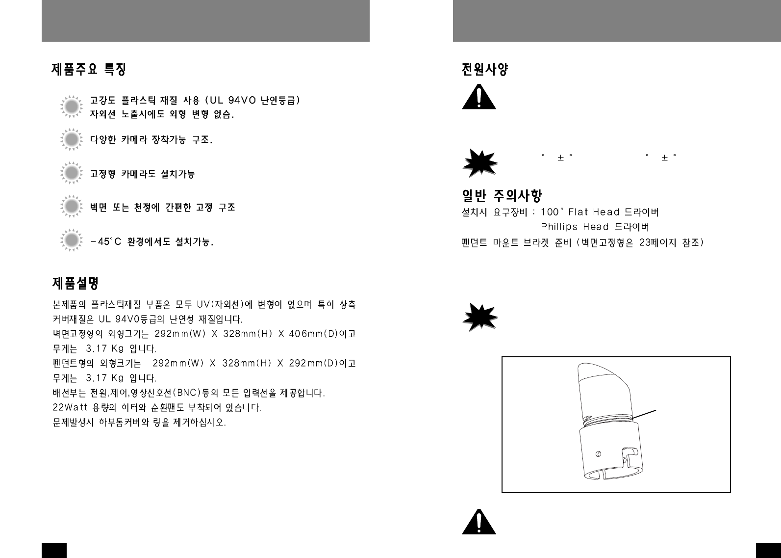
입력전압 :하우징 &카메라 -DC12V
DC12V인가시 22Watt
히터:20W
순환팬 :2W
1.조심해서 포장재를 제거한후 설명서를 참조하여 결품이 없는지 확인하십시오.
2.본제품은 11/2"NPT나사규격에 맞는 나사를 사용하고 있습니다.
3.벽면고정형 브라켓이나 펜던트파이프에 본체 커플링을 부착하세요.(그림1)
·
본제품을 연결해서 사용하시려면,11/2"NTP나사규격에 준하는 연결 pipe
를사용하세요.본 제품과 함께 제공되진 않습니다.별도로 구매하세요.
·
파이프의 나사산에는 녹이나 이물질이 없어야 됩니다.풀림방지를 위해 테
프론 테이프나 실리콘 실러를 사용하세요.
Figure 1
Add thread
sealing tape
본체의 무게를 지탱하기위해 브라켓은 벽면구조물에 단단히 고정되어야 합
니다.
(그림1)
NOTE
Notes
·
히터는 4
C ( 4C)
에서 동작하고 16
C ( 4C)
에서 멈춥니다.
·
순환팬은 항상 동작합니다.
NOTE
Notes
나사 돌림방지
테이프를 사용
하세요.
23
OUTDOOR DOME HOUSINGS
22
OUTDOOR DOME HOUSINGS
1.먼저 투명돔쪽의 하우징링에 체결되어 있는 스크류 3개를 푼후 하우징을 여
십시오. 스크류가 완전히 풀려서 빠지지 않도록 주의해야 합니다. 투명돔과
하우징링을 조심스럽게 반시계 방향으로 돌린후 하우징을 여십시오.(그림2)
2.팬틸트를 하우징내 원터치조립 브라켓에 조립하십시오.본 설치는 하우징
설치전에 행해져야 합니다.
3.이때 카메라본체를 설치하는것이 좋습니다.
카메라본체를 원터치조립 브라켓에 연결한후 사용설명서를 참조하여 단단
히 고정하십시오.
4.제공된 천으로 투명돔 안쪽을 깨끗이 닦습니다.
투명돔을 조립한후 스크류 3개소를 체결합니다.스크류체결시 과도한 힘을
주지 마세요.스크류 체결시 하우징링과 돔커버의 틈새가 없어질 정도만 체
결하십시오.
Figure 2
Loosen screws only,
do not remove
Remove dome by
twisting counter-
clockwise
본 설치는 하우징 설치전에 행해져야 합니다.
(그림2)
스크류가 완전히 빠
지지 않도록 풀어주
세요.
투명돔을 반시계방
향으로 돌려서 열어
주세요.
8-32 Security
fastener
Place for
connectors
Figure 3
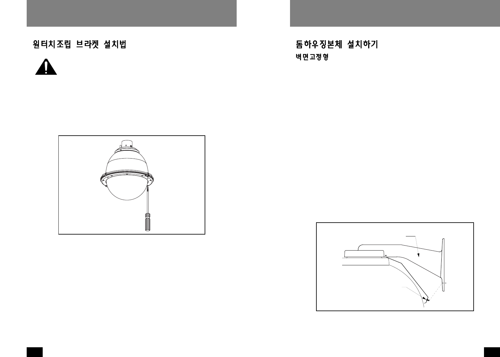
1.벽면고정형 브라켓의 용이한 설치를 위해 템플릿이 제공됩니다.우선 설치할
위치를 정한후 템플릿을 이용하여 드릴구멍을 표시합니다.브라켓상단의 2개
의 구멍에 3/4가량의 볼트(제공되지 않음)를 체결합니다. 벽면 밖으로 약
200mm길이의 배선을 뽑아내야 합니다.
2.벽면고정판의 스크류를 푼다음 커버를 엽니다.(그림3)
3.벽면에 체결된 볼트에 본체 브라켓의 상단 홀을 걸친후 벽면고정형 브라켓의
중앙부 사각홀로부터 배선을 뽑아냅니다. 본체 브라켓의 하단 홀에 와셔와
볼트를 단단히 고정시킵니다.본체 브라켓의 상단 홀의 볼트를 제거한후,볼
트에 와셔를 끼우고 단단히 고정시킵니다.
4.배선연결표를 참고하여 벽면으로부터 뽑아낸 배선에 제공된 컨넥터를 부착합
니다.
5.배선연결이 완료되었으면 배선을 본체 브라켓안으로 밀어넣은후 브라켓 커버
를 닫습니다.브라켓 커버 스크류를 다시 체결합니다.
6.제공된 천으로 돔의 외관면을 깨끗이 닦습니다.
(그림3)
컨넥터들은 여기에
위치 시켜주세요.
8-32유니파이나사
체결구 사용.
25
OUTDOOR DOME HOUSINGS
24
OUTDOOR DOME HOUSINGS
10 RXD (RS232) 청색
11 TXD (RS232) 자색
12 S1 + 회색
13 S1 - 주황색
14 S2 + 갈색
15 S2 - 황갈색
RS232통신과 디지털 경보
RS-485
1 Data + 회색
2 Data - 자색
3 Ground 청색
4 N/A
1.하우징 본체를 마운팅 브라켓과 커플링에 연결합니다. 배선연결시 편의를
위해 일시적으로 하우징본체를 지지하는 안전케이블이 연결되어 있습니다.
커플링에 체결된 세트스크류에 안전케이블을 걸고 제공된 컨넥터를 사용해
서 배선연결을 마무리합니다.
2.세트스크류에 걸린 안전케이블을푼후하우징 본체를 커플링에 끼운후 돌
려서 체결합니다. 하우징 커플링에 체결된 세트스크류를 단단히 조입니
다.(그림4)
3.제공된 천으로 돔의 외관면을 깨끗이 닦습니다.
Figure 4
Twist and
Secure
1악세사리 전원 (+12 VDC) 적색
2악세사리 전원 (Ground) 흑색
3N/A
4N/A
하우징 (전원 12VDC)
1 카메라 전원 (+12 VDC) 적색
2 카메라 전원 (Ground) 흑색
3 동기신호 (카메라 전원) 백색
4 N/A
카메라 (전원 12VDC)
1악세사리 전원 (24 VAC) 황색
2악세사리 전원 (24 VAC) 녹색
3N/A
4N/A
하우징 (전원 24VAC)
1 카메라 전원 (+12 VDC) 적색
2 카메라 전원 (Ground) 흑색
3 동기신호 (카메라 전원) 백색
4 N/A
카메라 (전원 12VDC)
(그림4)
돌려서 체결하세요
27
OUTDOOR DOME HOUSINGS
26
OUTDOOR DOME HOUSINGS
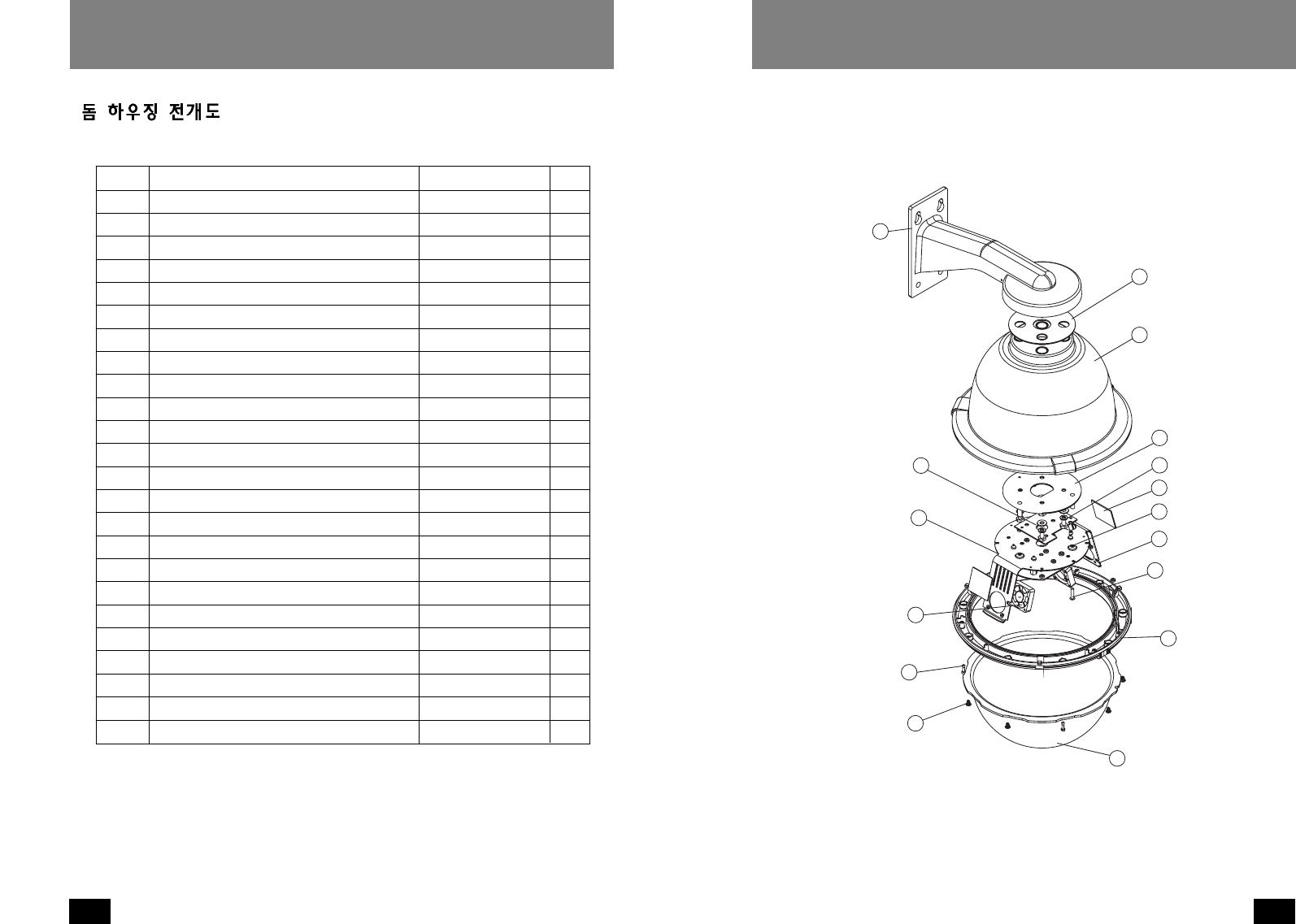
번호 품 명 품번 수량
1 Wall Mount Bracket Assembly 40-BRWM12 1
2 Housing Top 30-VL1697 1
3 Dome Support Ring 30-VL1695 1
4 20W, 12 VDC Heater 72-HT2170 1
n/s Clear Dome 20-DCFD8 1
5 Tinted Dome 20-DTFD8 1
n/s 9.25" O-ring 96-RSORG11 2
6 Plastic Ring Plugs 30-VL1696 6
7 1
8 Upper Housing Bracket 30-VL1744 1
9 Housing Gasket 96-PSGK05 3
10 Housing Fan 71-VLBL03 1
11 1
12 1/4 x 20 x .75" HH Bolts 90-BTHH27 4
12 1/4 Split Lock Washer 92-WSSL01 4
12 1/4 Flat Washer 92-WSFL01 4
13 10 x 32 x .75 Phil PH SS 90-BTRP28 3
15 Captive Screw 30-VL1749 3
n/s Captive Screw Spring 92-SPR01 3
n/s Captive Screw Retainer 94-FSRT04 3
16 Main Housing Bracket 30-VL1742 1
n/s Housing Ring 1" Lanyard Spring 92-SPR02 1
n/s Lanyard Spring Screws 90-BTPEM01 2
n/s Packet Assembly 40-PKFD8 1
16
15
7
13
12
11
10
9
8
7
6
5
4
3
2
1
벽면고정형 (For SPH-20W, SWH-20W)
29
OUTDOOR DOME HOUSINGS
28
OUTDOOR DOME HOUSINGS
17 1/4 x 20 FH SS Bolt 90-BTSR01 1
18 Housing Pendent Bracket 30-VL926 1
19 1/4 Split Lock Washer 92-WSSL01 1
20 1/4 Flat Washer 92-WSFL01 1
21 Housing Gasket 96-PSGK05 1
22 1/4 x 20 x 1/2" Set Screw 90-BTSS05 2
23 1/4 Flat Washer 92-WSFL01 4
24 1/4 Split Lock Washer 92-WSSL01 4
25 1/4 x 20 x .75" HH Bolts 90-BTHH27 4
26 1 1/2" Housing Coupling 30-VL917 1
27 Upper Housing Gasket 96-PSGK04 1
28 1/4 x 20 x .375" HH Bolts 90-BTHH39 2
n/s 1/4 Flat Washer 92-WSFL01 2
n/s 1/4 Split Lock Washer 92-WSSL01 2
28
27
26
25 24
23
22
21
20
19
18
17
펜던트형 (For SPH-20P, SWH-20P)
50mm
38mm
22mm
50mm
140mm
31
OUTDOOR DOME HOUSINGS
30
OUTDOOR DOME HOUSINGS
Speed Dome Housings
118mm
408mm
202mm
224mm
290mm
57mm
224mm
226mm
45mm
벽면고정형
펜던트형

33
OUTDOOR DOME HOUSINGS
32
OUTDOOR DOME HOUSINGS
MEMO MEMO
