Sanitag Technologies AT00123H RFID device User Manual Litum Software
Sanitag Technologies Corporation RFID device Litum Software
User Manual

Setting Up Devices & RF Netwowk
V.200.15
THIS DOCUMENT IS THE PROPERTY OF SANITAG COMPANY. IT MAY NOT BE COPIED AND REPRODUCED WITHOUT WRITTEN PERMISSION OF SANITAG
COMPANY. COPYRIGHT NOTICES MAY NOT BE REMOVED
SANITAG RTLS TECHNOLOGIES
Cumhuriyet Bulvarı No: 45/9 Pamuk Plaza - Pasaport, İzmir
Tel: +90 (232) 465 0002 Fax: +90 (232) 464 4408
www.sanitag.com
Healthcare - Real Time Location
System
(HRTLS)
SETTING UP DEVICES & RF NETWORK

Setting Up Devices & RF Netwowk
-i- V.200.15
THIS DOCUMENT IS THE PROPERTY OF SANITAG COMPANY. IT MAY NOT BE COPIED AND REPRODUCED WITHOUT WRITTEN PERMISSION OF SANITAG
COMPANY. COPYRIGHT NOTICES MAY NOT BE REMOVED
CONTENT
1. SETTING UP DEVICES & RF NETWORK ..................................................................... 1-1
1.1. Safety .................................................................................................................. 1-1
1.2. Introduction .......................................................................................................... 1-1
1.1. Device Definitions ................................................................................................ 1-4
1.1.1. Sanitag AC-001-LAN (Wireless Router) ................................................... 1-4
1.1.2. Active RFID Room Level Reader (Sanitag Model No: AR-001-HLR) &
Active RFID Long Range Reader (Sanitag Model No: AR-002-HLR) ....... 1-5
1.1.3. Active RFID Tag for Patients (Sanitag Model No: AT-001-H) ................... 1-6
1.1.4. Active RFID Tag for New Born Babies (Sanitag Model No: AT-002-H) ..... 1-7
1.1.5. Active RFID Tag for Assets (Sanitag Model No: AT-003-H) ..................... 1-8
1.1.6. Active RFID Tag for New Staff/Doctors (Sanitag AT-004-H) ..................... 1-9
1.2. Configuration ..................................................................................................... 1-10
1.2.1. Service Manager Software ..................................................................... 1-10
1.2.2. Configuration of Sanitag AC-001-LAN Router ....................................... 1-10
1.2.3. Prepare/Configure Sanitag AC-001-LAN Router with Ethernet
interface ................................................................................................. 1-10
1.2.4. Prepare/Configure Sanitag AC-001-LAN Router for Com Port ............... 1-12
1.2.5. Prepare RF Network .............................................................................. 1-13
1.3. An Analogy on an Active Instance of the Location Provider ............................... 1-14

Setting Up Devices & RF Netwowk
1-1
THIS DOCUMENT IS THE PROPERTY OF SANITAG COMPANY. IT MAY NOT BE COPIED AND REPRODUCED WITHOUT WRITTEN PERMISSION OF SANITAG
COMPANY. COPYRIGHT NOTICES MAY NOT BE REMOVED
Setting Up Devices & RF Netwowk
1-1
THIS DOCUMENT IS THE PROPERTY OF SANITAG COMPANY. IT MAY NOT BE COPIED AND REPRODUCED WITHOUT WRITTEN PERMISSION OF SANITAG
COMPANY. COPYRIGHT NOTICES MAY NOT BE REMOVED
1. SETTING UP DEVICES & RF NETWORK
Rest of the manual guides you through the steps necessary for setting up and configuring
your Sanitag devices. Please read this manual before system setup.
1.1. Safety
The device must be used solely with its original power adaptor. Please note that the
adapter is 110/220V AC
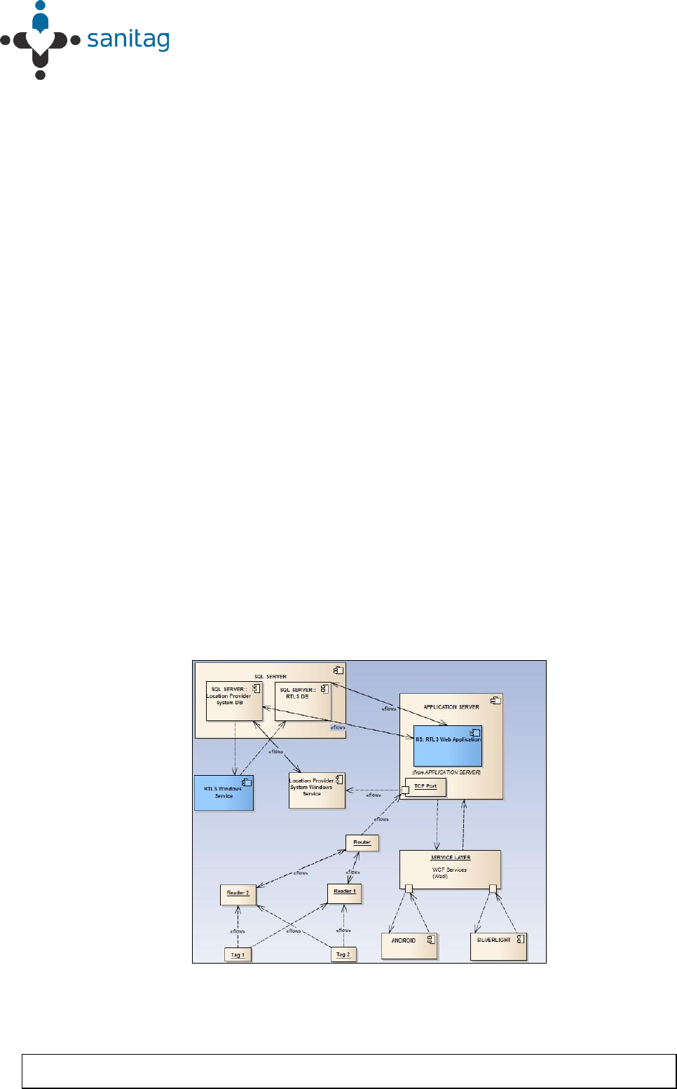
1.2. Introduction
Sanitag devices are based on 2.4GHZ IEEE 802.15.4 compliant RF wireless network. To
form a minimal 802.15.4 RF Network, you should have at least 1-Router, 1-Reader and
Mobile Devices.
Main coordinator (router) establishes a mesh network once it is installed. Each plugged
reader (receiver), attends this network automatically and relays data for the network. All
reader nodes cooperate in the distribution of data in the network.
Sanitag’s small sized newborn baby tag is affixed to the ankle of the newborn infant to be
tracked. The tag contains an RF transmitter circuit. It transmits message signal,
comprising unique identity information, to receivers which are strategically placed within
the hospital. The message is propagated along a path by hopping from node to node until
it reaches the port wihch is being listened by the Location Provider Service software.
Location Provider Software calculates tags’ positions by using RSSI (received signal
strength indicator) levels, dimensions of the region to be tracked and fixed position
information of the receivers on that region.
Figure 1- Component Interoperability

Setting Up Devices & RF Netwowk
1-2
THIS DOCUMENT IS THE PROPERTY OF SANITAG COMPANY. IT MAY NOT BE COPIED AND REPRODUCED WITHOUT WRITTEN PERMISSION OF SANITAG
COMPANY. COPYRIGHT NOTICES MAY NOT BE REMOVED
Calculated positions are being written on the Location Provider System database. These
positions can also be used in real time by remoting technology. This architecture provides
flexiblity in integration with third party softwares. Sanitag H-RTLS application comprises
an independent service which listens the Location Provider System database. It
interpretes fetched information and applies some business rules on it prior to UI
interaction.
Tags comprise a conductive security element attachment having two ends, whose
electrical state will change when stretched, severed, or removed by parting the end.
When the electrical state changes an alarm code will be generated and sent to receivers.
This information will then be processed as explained above.
Built in motion sensor is able to detect unnatural movements like falling, being idle for a
certain period of time etc. Alarm will be generated as soon as this kind of movement is
detected.
1.3. RF affecting factors
All devices's RF signals can affect some material some extent. İf our devices's RF signal
encounter some material especially high-level obstacle severity material as stated in
Table 1. Router, Reader and Tags will be decreased range of distance. For this reason,
all device have to position as far as possible from especially obstruction of high level
obstacle severity material as in Table 1.
Setting Up Devices & RF Netwowk
1-3
THIS DOCUMENT IS THE PROPERTY OF SANITAG COMPANY. IT MAY NOT BE COPIED AND REPRODUCED WITHOUT WRITTEN PERMISSION OF SANITAG
COMPANY. COPYRIGHT NOTICES MAY NOT BE REMOVED
Obstruction
Obstacle
Severity
Sample Use
Wood / Wood paneling
Low
İnside a wall or hollow door
Drywall
Low
İnside Walls
Furniture
Low
Couches or office partitions
Clear glass
Low
Windows
Tinted glass
Medium
Windows
People
Medium
High-volume traffic areas that
have consirable pedestrian
traffic
Ceramic tile
Medium
Walls
Concrete blocks
Medium/High
Outer wall construction
Mirrors
High
Mirror or reflective glass
Metals
High
Metal office partitions, doors,
metal office furniture
Water
High
Aquariums, rain, fauntains
Table-1 RF Obstacles Found Indoors

Setting Up Devices & RF Netwowk
1-4
THIS DOCUMENT IS THE PROPERTY OF SANITAG COMPANY. IT MAY NOT BE COPIED AND REPRODUCED WITHOUT WRITTEN PERMISSION OF SANITAG
COMPANY. COPYRIGHT NOTICES MAY NOT BE REMOVED
1.1. Device Definitions
1.1.1. Sanitag AC-001-LAN (Wireless Router)
Router is hierarchically the top-most Node of 802.15.4 RF Network . It forms/manages RF
Network, collects all RF Network data and behaves as a gateway from RF Network to
upper media. There are two type of Router:
Router with Ethernet Interface: Redirects RF network traffic to a prederfined “IP:Port”
over ethernet via TCP/IP protocol.
Router with USB Virtual Com Port Interface: Redirects RF network traffic to Serial
Port.
Router device has blue leds on itself.
If leds blink, it means that the router device tries to form Rf network.
If leds lighten constantly, it means that the router device forms Rf Network
succesfully.
Sanitag AC-001-LAN device has RF propagation that 2.5 dBm output power level and it
has 2,4 GHz uFl tranmitter antenna which is has 2dBi gain.
Also, AC-00-H device has UWB module that has 3.1 ~ 8 GHz monopole antenna. We
operation at 4.4GHz due to special reason. UWB Module output power is fully adjustable
from 0 dBm to 15.5 dBm via firmware.
The antenna that using on Sanitag AC-001-LAN is wire antenna which is fixed on PCB,
That's why İt cannot change reorient and relocate.The device's antenna type is
omnidirectional. Therefore, the Sanitag AC-001-LAN can take signal every direction. If
Sanitag AC-001-LAN obstructs by obstacle of in Table 1. The device’s RF signal will
decrease as stated in Table 1.
THIS DEVICE COMPLIES WITH PART 15 OF THE FCC RULES. OPERATION IS
SUBJECT TO THE FOLLOWING TWO CONDITIONS.
(1) THIS DEVICE MAY NOT CAUSE HARMFUL INTERFERENCE, AND (2) THIS
DEVICE MUST ACCEPT ANY INTERFERENCE RECEIVED, INCLUDING
INTERFERENCE THAT MAY CAUSE UNDESIRED OPERATION.
Warning: Changes or modifications not expressly approved by the party responsible for
compliance could void the user’s authority to operate this equipment.
Note: This equipment has been tested and found to comply with the limits for a Class B
digital device, pursuant to part 15 of the FCC Rules. These limits are designed to provide
reasonable protection against harmful interference in a residential installation. This
equipment generates, uses and can radiate radio frequency energy and, if not installed
and used in accordance with the instructions, may cause harmful interference to radio
communications.However, there is no guarantee that interference will not occur in a
particular installation. If this equipment does cause harmful interference to radio or
television reception, which can be determined by turning the equipment off and on, the

Setting Up Devices & RF Netwowk
1-5
THIS DOCUMENT IS THE PROPERTY OF SANITAG COMPANY. IT MAY NOT BE COPIED AND REPRODUCED WITHOUT WRITTEN PERMISSION OF SANITAG
COMPANY. COPYRIGHT NOTICES MAY NOT BE REMOVED
user is encouraged to try to correct the interference by one or more of the following
measures:
—Reorient or relocate the receiving antenna.
—Increase the separation between the equipment and receiver.
—Connect the equipment into an outlet on a circuit different from that to which the receiver
is connected.
—Consult the dealer or an experienced radio/TV technician for help.
1.1.2. Active RFID Room Level Reader (Sanitag Model No: AR-001-HLR) &
Active RFID Long Range Reader (Sanitag Model No: AR-002-HLR)
These devices are hierarchically below Router or upper level Reader on network. It
collects Mobile Beacon Messages and also sub-level Reader messages and then routes
them to the upper level Reader or Router. It has also blue leds on itself.
If leds blink, it means that the reader device searches to join Rf network. So it implies that
the reader is not joined any Rf network yet.
If leds ligthen constantly, it means that the reader device joins Rf Network succesfully.
Sanitag AR-001-HLR device has RF propagation that 2.5dBm output power level and it
has 2,4 GHz uFl tranmitter antenna which is has 2dBi gain. Sanitag AR-002-HLR device
has RF propagation that 22dBm output power level and it has 2,4 GHz uFl tranmitter
antenna which is has 2dBi gain.
Also, AR-001-HLR and AR-002-HLR devices have UWB module that has 3.1 ~ 8 GHz
monopole antenna. We operation at 4.4GHz due to special reason. UWB Module output
power is fully adjustable from 0 dBm to 15.5 dBm via firmware.
The antenna that using on Sanitag AR-001-HLR and Sanitag AR-002-HLR are wire
antenna which is fixed on PCB, That's why İt cannot change reorient and relocate.The
device's antenna type is omnidirectional. Therefore, the Sanitag AR-001-HLR and
Sanitag AR-002-HLR can take signal every direction. İf devices obstruct by obstacle of in
Table 1. The device’s RF signal will decrease as stated in Table 1.
THIS DEVICE COMPLIES WITH PART 15 OF THE FCC RULES. OPERATION IS
SUBJECT TO THE FOLLOWING TWO CONDITIONS.
(1) THIS DEVICE MAY NOT CAUSE HARMFUL INTERFERENCE, AND (2) THIS
DEVICE MUST ACCEPT ANY INTERFERENCE RECEIVED, INCLUDING
INTERFERENCE THAT MAY CAUSE UNDESIRED OPERATION.
Warning: Changes or modifications not expressly approved by the party responsible for
compliance could void the user’s authority to operate this equipment.
Note: This equipment has been tested and found to comply with the limits for a Class B
digital device, pursuant to part 15 of the FCC Rules. These limits are designed to provide

Setting Up Devices & RF Netwowk
1-6
THIS DOCUMENT IS THE PROPERTY OF SANITAG COMPANY. IT MAY NOT BE COPIED AND REPRODUCED WITHOUT WRITTEN PERMISSION OF SANITAG
COMPANY. COPYRIGHT NOTICES MAY NOT BE REMOVED
reasonable protection against harmful interference in a residential installation. This
equipment generates, uses and can radiate radio frequency energy and, if not installed
and used in accordance with the instructions, may cause harmful interference to radio
communications.However, there is no guarantee that interference will not occur in a
particular installation. If this equipment does cause harmful interference to radio or
television reception, which can be determined by turning the equipment off and on, the
user is encouraged to try to correct the interference by one or more of the following
measures:
—Reorient or relocate the receiving antenna.
—Increase the separation between the equipment and receiver.
—Connect the equipment into an outlet on a circuit different from that to which the
receiver is connected.
—Consult the dealer or an experienced radio/TV technician for help.
1.1.3. Active RFID Tag for Patients (Sanitag Model No: AT-001-H)
It has two leds (Blue, Yellow) If device is powered up, Blue led blinks by each wake/sleep
cycle. There is no led indication in stand-by mode. It has one button with following
functions:
Button Short Press/Release : Send Emergency Message / Wake-up the device if
in stand-by
Button Press for 5 Seconds: Enter to standby mode.
This button is also used for matching mobile devices.
Sanitag AT-001-H device has 2.4GHz RF propagation that 2.5dBm output power level
and it has 2,4 GHz Pcb antenna. Also, AT-001-H device has UWB module that has 3.1
~ 8 GHz monopole antenna. We operation at 4.4GHz due to special reason. UWB
Module output power is fully adjustable from 0 dBm to 15.5 dBm via firmware.
The device’s both of PCB antenna and UWB monopole antenna are omnidirectional. Both
of antenna are fixed on PCB, that's why İt cannot change reorient and relocate.
Therefore AT-001-H can take signal every direction. İf Sanitag AT-001-H obstructs by
obstacle of in Table 1. The device’s RF signal will decrease as stated in Table 1.
AT-001-H can transmit until 200 meters to readers if RF output power is fully.
THIS DEVICE COMPLIES WITH PART 15 OF THE FCC RULES. OPERATION IS
SUBJECT TO THE FOLLOWING TWO CONDITIONS.
(1) THIS DEVICE MAY NOT CAUSE HARMFUL INTERFERENCE, AND (2) THIS
DEVICE MUST ACCEPT ANY INTERFERENCE RECEIVED, INCLUDING
INTERFERENCE THAT MAY CAUSE UNDESIRED OPERATION.
Warning: Changes or modifications not expressly approved by the party responsible for
compliance could void the user’s authority to operate this equipment.
Note: This equipment has been tested and found to comply with the limits for a Class B

Setting Up Devices & RF Netwowk
1-7
THIS DOCUMENT IS THE PROPERTY OF SANITAG COMPANY. IT MAY NOT BE COPIED AND REPRODUCED WITHOUT WRITTEN PERMISSION OF SANITAG
COMPANY. COPYRIGHT NOTICES MAY NOT BE REMOVED
digital device, pursuant to part 15 of the FCC Rules. These limits are designed to provide
reasonable protection against harmful interference in a residential installation. This
equipment generates, uses and can radiate radio frequency energy and, if not installed
and used in accordance with the instructions, may cause harmful interference to radio
communications.However, there is no guarantee that interference will not occur in a
particular installation. If this equipment does cause harmful interference to radio or
television reception, which can be determined by turning the equipment off and on, the
user is encouraged to try to correct the interference by one or more of the following
measures:
—Reorient or relocate the receiving antenna.
—Increase the separation between the equipment and receiver.
—Connect the equipment into an outlet on a circuit different from that to which the receiver
is connected.
—Consult the dealer or an experienced radio/TV technician for help.
1.1.4. Active RFID Tag for New Born Babies (Sanitag Model No: AT-002-H)
It has two leds (Blue, Yellow) If device is powered up, Blue led blinks by each wake/sleep
cycle. There is no led indication in stand-by mode.It has one button with following
functions:
Button Short Press/Release : Send Emergency Message / Wake-up the device if
in stand-by
Button Press for 5 Seconds: Enter to standby mode.
This button is also used for matching mobile devices.
Sanitag AT-002-H device has 2.4GHz RF propagation that 2.5dBm output power level
and it has 2,4 GHz Pcb antenna. Also, AT-002-H device has UWB module that has 3.1
~ 8 GHz monopole antenna. We operation at 4.4GHz due to special reason. UWB
Module output power is fully adjustable from 0 dBm to 15.5 dBm via firmware.
The device’s both of PCB antenna and UWB monopole antenna are omnidirectional. Both
of antenna are fixed on PCB, that's why İt cannot change reorient and relocate.
Therefore AT-002-H can take signal every direction. İf Sanitag AT-002-H obstructs by
obstacle of in Table 1. The device’s RF signal will decrease as stated in Table 1.
AT-002-H can transmit until 200 meters to readers if RF output power is fully.
THIS DEVICE COMPLIES WITH PART 15 OF THE FCC RULES. OPERATION IS
SUBJECT TO THE FOLLOWING TWO CONDITIONS.
(1) THIS DEVICE MAY NOT CAUSE HARMFUL INTERFERENCE, AND (2) THIS
DEVICE MUST ACCEPT ANY INTERFERENCE RECEIVED, INCLUDING
INTERFERENCE THAT MAY CAUSE UNDESIRED OPERATION.
Warning: Changes or modifications not expressly approved by the party responsible for
compliance could void the user’s authority to operate this equipment.

Setting Up Devices & RF Netwowk
1-8
THIS DOCUMENT IS THE PROPERTY OF SANITAG COMPANY. IT MAY NOT BE COPIED AND REPRODUCED WITHOUT WRITTEN PERMISSION OF SANITAG
COMPANY. COPYRIGHT NOTICES MAY NOT BE REMOVED
Note: This equipment has been tested and found to comply with the limits for a Class B
digital device, pursuant to part 15 of the FCC Rules. These limits are designed to provide
reasonable protection against harmful interference in a residential installation. This
equipment generates, uses and can radiate radio frequency energy and, if not installed
and used in accordance with the instructions, may cause harmful interference to radio
communications.However, there is no guarantee that interference will not occur in a
particular installation. If this equipment does cause harmful interference to radio or
television reception, which can be determined by turning the equipment off and on, the
user is encouraged to try to correct the interference by one or more of the following
measures:
—Reorient or relocate the receiving antenna.
—Increase the separation between the equipment and receiver.
—Connect the equipment into an outlet on a circuit different from that to which the
receiver is connected.
—Consult the dealer or an experienced radio/TV technician for help.
1.1.5. Active RFID Tag for Assets (Sanitag Model No: AT-003-H)
It has two leds (Green, Red) If device is powered up , Green led blinks by each
wake/sleep cycle. There is no led indication in stand-by mode. It has one button with
following functions:
Button Short Press/Release : Send Emergency Message / Wake the device up if
in stand-by
Button Press for 5 Seconds: Enter to standby mode.
Sanitag AT-003-H device has 2.4GHz RF propagation that 2.5dBm output power level
and it has 2,4 GHz Pcb antenna. Also, AT-003-H device has UWB module that has 3.1 ~
8 GHz monopole antenna. We operation at 4.4GHz due to special reason. UWB Module
output power is fully adjustable from 0 dBm to 15.5 dBm via firmware.
The device’s both of PCB antenna and UWB monopole antenna are omnidirectional. Both
of antenna are fixed on PCB, that's why İt cannot change reorient and relocate.
Therefore AT-003-H can take signal every direction. İf Sanitag AT-003-H obstructs by
obstacle of in Table 1. The device’s RF signal will decrease as stated in Table 1.
AT-003-H can transmit until 200 meters to readers if RF output power is fully.
THIS DEVICE COMPLIES WITH PART 15 OF THE FCC RULES. OPERATION IS
SUBJECT TO THE FOLLOWING TWO CONDITIONS.
(1) THIS DEVICE MAY NOT CAUSE HARMFUL INTERFERENCE, AND (2) THIS
DEVICE MUST ACCEPT ANY INTERFERENCE RECEIVED, INCLUDING
INTERFERENCE THAT MAY CAUSE UNDESIRED OPERATION.
Warning: Changes or modifications not expressly approved by the party responsible for
compliance could void the user’s authority to operate this equipment.

Setting Up Devices & RF Netwowk
1-9
THIS DOCUMENT IS THE PROPERTY OF SANITAG COMPANY. IT MAY NOT BE COPIED AND REPRODUCED WITHOUT WRITTEN PERMISSION OF SANITAG
COMPANY. COPYRIGHT NOTICES MAY NOT BE REMOVED
Note: This equipment has been tested and found to comply with the limits for a Class B
digital device, pursuant to part 15 of the FCC Rules. These limits are designed to provide
reasonable protection against harmful interference in a residential installation. This
equipment generates, uses and can radiate radio frequency energy and, if not installed
and used in accordance with the instructions, may cause harmful interference to radio
communications.However, there is no guarantee that interference will not occur in a
particular installation. If this equipment does cause harmful interference to radio or
television reception, which can be determined by turning the equipment off and on, the
user is encouraged to try to correct the interference by one or more of the following
measures:
—Reorient or relocate the receiving antenna.
—Increase the separation between the equipment and receiver.
—Connect the equipment into an outlet on a circuit different from that to which the
receiver is connected.
—Consult the dealer or an experienced radio/TV technician for help.
1.1.6. Active RFID Tag for New Staff/Doctors (Sanitag AT-004-H)
It has two leds (Green, Red) If device is powered up, Green led blinks by each
wake/sleep cycle. In stand-by mode, there is no led indication.It has two buttons (Orange,
Blue) with following functions:
Orange Button Short Press/Release: Send Emergency Message / Wake-up the if
in stand-by
Orange Button Press for 5 Seconds: Enter to standby mode.
Blue button is used for matching mobile devices.
Sanitag AT-004-H device has 2.4GHz RF propagation that 2.5dBm output power level
and it has 2,4 GHz Pcb antenna. Also, AT-004-H device has UWB module that has 3.1 ~
8 GHz monopole antenna. We operation at 4.4GHz due to special reason. UWB Module
output power is fully adjustable from 0 dBm to 15.5 dBm via firmware.
The device’s both of PCB antenna and UWB monopole antenna are omnidirectional. Both
of antenna are fixed on PCB, that's why İt cannot change reorient and relocate.
Therefore AT-004-H can take signal every direction. İf Sanitag AT-004-H obstructs by
obstacle of in Table 1. The device’s RF signal will decrease as stated in Table 1.
AT-004-H can transmit until 200 meters to readers if RF output power is fully.
THIS DEVICE COMPLIES WITH PART 15 OF THE FCC RULES. OPERATION IS
SUBJECT TO THE FOLLOWING TWO CONDITIONS.
(1) THIS DEVICE MAY NOT CAUSE HARMFUL INTERFERENCE, AND (2) THIS
DEVICE MUST ACCEPT ANY INTERFERENCE RECEIVED, INCLUDING
INTERFERENCE THAT MAY CAUSE UNDESIRED OPERATION.
Warning: Changes or modifications not expressly approved by the party responsible for
compliance could void the user’s authority to operate this equipment.

Setting Up Devices & RF Netwowk
1-10
THIS DOCUMENT IS THE PROPERTY OF SANITAG COMPANY. IT MAY NOT BE COPIED AND REPRODUCED WITHOUT WRITTEN PERMISSION OF SANITAG
COMPANY. COPYRIGHT NOTICES MAY NOT BE REMOVED
Note: This equipment has been tested and found to comply with the limits for a Class B
digital device, pursuant to part 15 of the FCC Rules. These limits are designed to provide
reasonable protection against harmful interference in a residential installation. This
equipment generates, uses and can radiate radio frequency energy and, if not installed
and used in accordance with the instructions, may cause harmful interference to radio
communications.However, there is no guarantee that interference will not occur in a
particular installation. If this equipment does cause harmful interference to radio or
television reception, which can be determined by turning the equipment off and on, the
user is encouraged to try to correct the interference by one or more of the following
measures:
—Reorient or relocate the receiving antenna.
—Increase the separation between the equipment and receiver.
—Connect the equipment into an outlet on a circuit different from that to which the
receiver is connected.
—Consult the dealer or an experienced radio/TV technician for help.
1.2. Configuration
1.2.1. Service Manager Software
Service Manager is a PC based console application. It listens a predefined COM Port for
incoming connections. Sanitag AC-001-LAN Router connects to this COM Port and then
redirects all RF network data traffic to the Service Manager. After connection estabilished,
Service Manager dumps received data with human readable format. For instance:
A line with tag “MID:33000” indicates a data receive from Mobile Device with ID =
33000,
A line with tag “RNID:201” indicates a data receive from Reader with Device ID =
201
1.2.2. Configuration of Sanitag AC-001-LAN Router
Depending type of AC-001-LAN Router, proceed following steps:
AC-001-LAN With Ethernet Interface: Proceed steps 1.2.3
AC-001-LAN with Virtual Com Port: Proceed steps 1.2.4
1.2.3. Prepare/Configure Sanitag AC-001-LAN Router with Ethernet
Interface
Step 1. In order to access Router’s http page, you need to Connect AC-001-LAN
Router to your computer with Ethernet cross cable temporarily.
Step 2. The default IP address of Router Ethernet Module is 192.168.1.250 and
subnet Mask 255.255.255.0. Open web browser and type the following
address “http:\\192.168.1.250” (You may need also change your computer
IP address as “192.168.1.x” and Subnet Mask 255.255.255.0 )
Setting Up Devices & RF Netwowk
1-11
THIS DOCUMENT IS THE PROPERTY OF SANITAG COMPANY. IT MAY NOT BE COPIED AND REPRODUCED WITHOUT WRITTEN PERMISSION OF SANITAG
COMPANY. COPYRIGHT NOTICES MAY NOT BE REMOVED
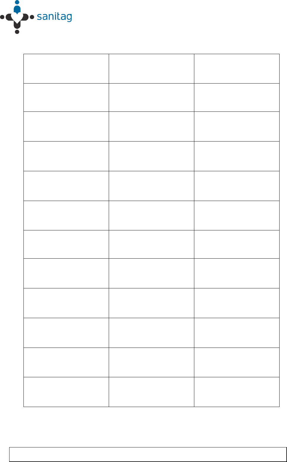
Step 3. There will be appear login window, leave blank the fields User ID and
Password and press OK
Figure 2 - Component Interoperability
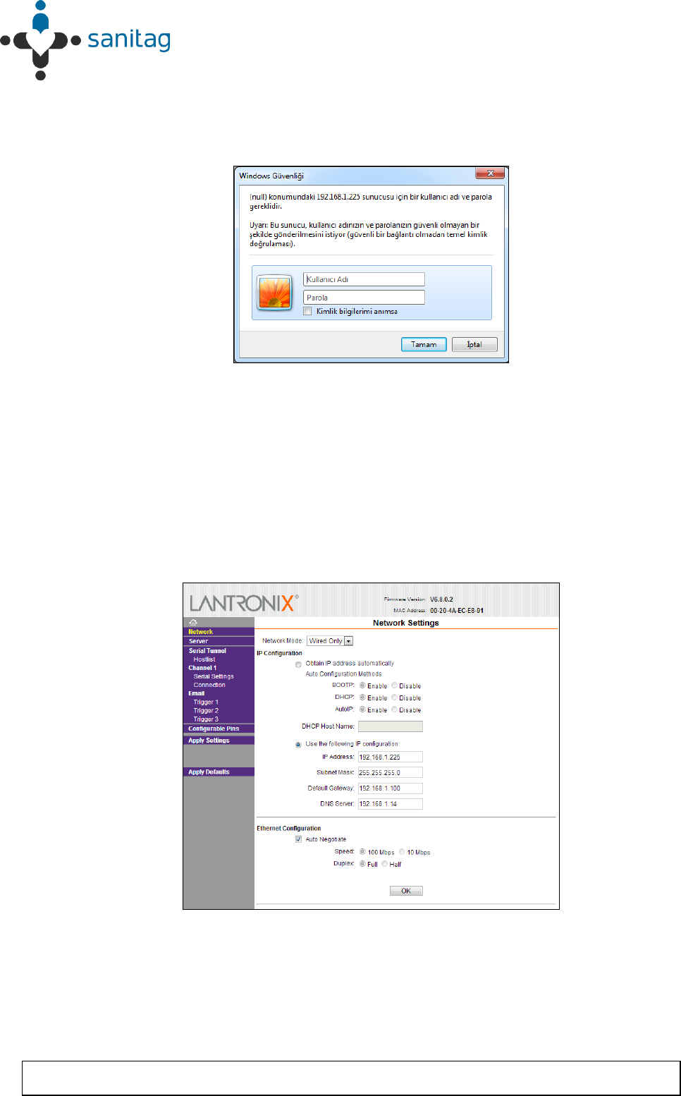
Step 4. In “Network” menu, you can assign “IP/Subnet Mask” to the AC-001-LAN
Router in accordance with your Local Area Network (LAN) address
segment and subnet mask. Enter following fields and then press “OK”
Address = “Router IP Address”
Subnet Mask = “Subnet Mask”
Figure 3- Router Config via Ethernet 1
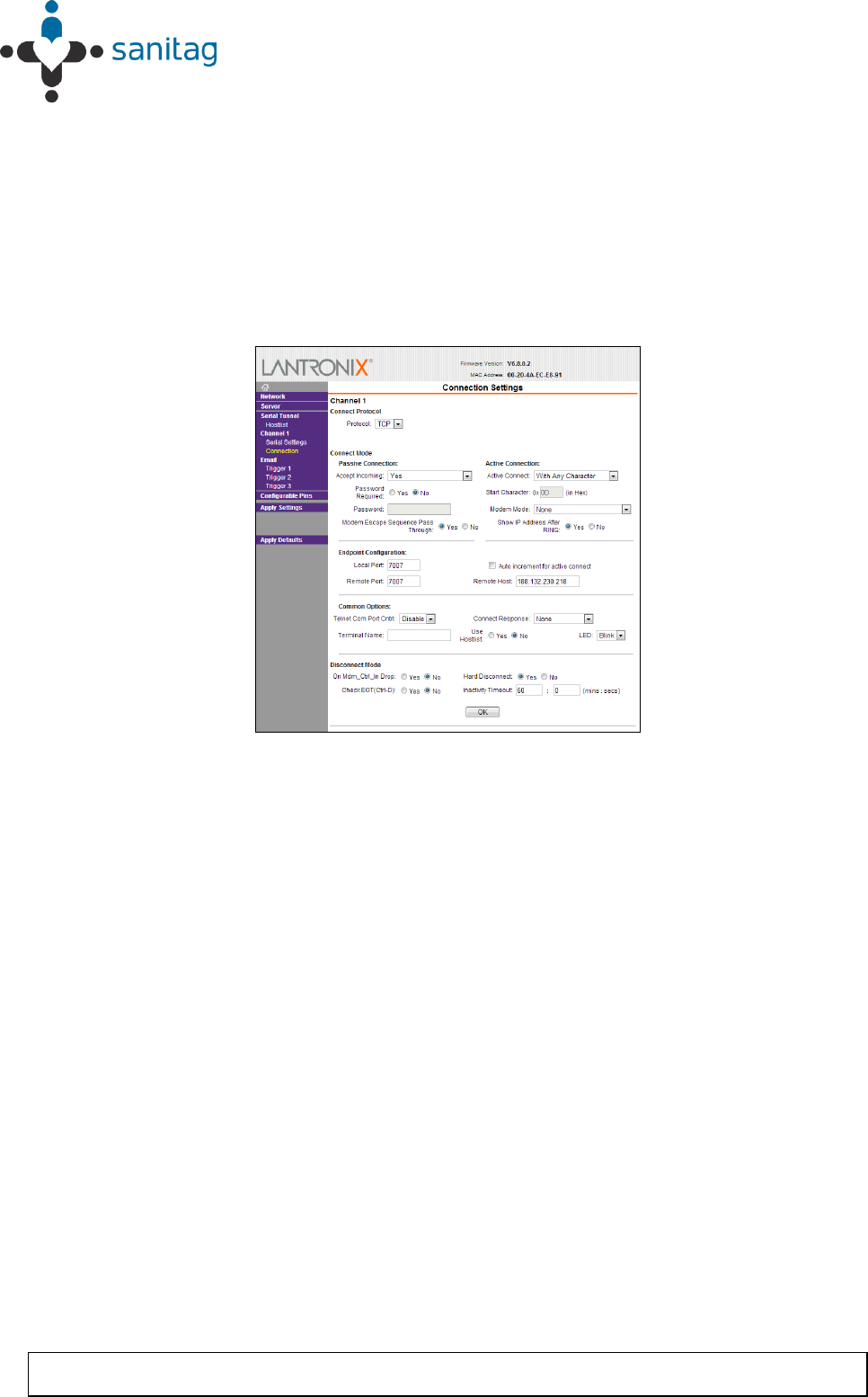
Step 5. In “Server -> Configuration” menu enter following fields as;
Protocol = TCP
Setting Up Devices & RF Netwowk
1-12
THIS DOCUMENT IS THE PROPERTY OF SANITAG COMPANY. IT MAY NOT BE COPIED AND REPRODUCED WITHOUT WRITTEN PERMISSION OF SANITAG
COMPANY. COPYRIGHT NOTICES MAY NOT BE REMOVED
Remote Host = “Target computer IP where “Wipelot Service Manager” have
been installed”
Local Port = 7021
Remote Port = 7021
Leave others fields with default values.
Press “OK”
Press “Apply Settings” and then Router Ethernet module will reboot with
new configuration.
Figure 4- Router Config via Ethernet 2
Step 6. Unplug cross-cable and revert your computer’s IP Address and Subnet
Mask back.
1.2.3.1. Install/Configure Wipelot Service Manager Software for Ethernet
Step 7. Connect your PC to the Local Network (LAN).
Step 8. Be sure you correctly assigned to your computer IP address with same
address we previously assigned to AC-001-LAN Router
Step 9. Copy folder named “Service Manager” to your computer hard drive.
Step 10. Open following xml file with a text editor like notepad.
\WipelotService\WipelotServiceManager.exe.config
Step 11. Change following field with the address which previously we assigned it for
AC-001-LAN Router; TCPListeningIP = “Router IP Address”
Step 12. Save and close xml file.
Step 13. Run “WipelotServiceManager.exe”
Now, Service Manager will start to listen TCP port 7021. And accepts incoming
connection requests.
1.2.4. Prepare/Configure Sanitag AC-001-LAN Router for Com Port
Setting Up Devices & RF Netwowk
1-13
THIS DOCUMENT IS THE PROPERTY OF SANITAG COMPANY. IT MAY NOT BE COPIED AND REPRODUCED WITHOUT WRITTEN PERMISSION OF SANITAG
COMPANY. COPYRIGHT NOTICES MAY NOT BE REMOVED
Step 14. Install FTDI Virtual Com Port Driver. (For up-to date driver please visit
http://www.ftdichip.com)
Step 15. Connect Sanitag AC-001-LAN Router to your Host computer with USB
cable. There you will see “Found New Hardware” and then driver will be
installed automatically by hardware wizard.
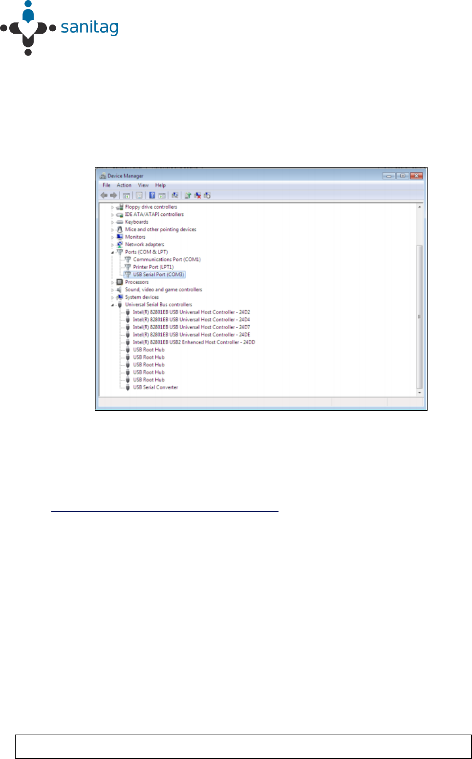
Step 16. Verify that a new “Com Port” added to Windows Device Tree.
Figure 5- Router Config via Com Port 1
1.2.4.1. Install/Configure Wipelot Service Manager Software for Com
Port
Step 17. Copy folder named “Service Manager” to your computer hard drive.
Step 18. Open following xml file with a text editor like notepad.
\WipelotService\WipelotServiceManager.exe.config
Step 19. Change following fields properly (Use the same Com Port Number which
you previously see under Windows Device Tree)
SerialPortActive = “1”
SerialPortComPort = “3”
SerialPortConnectionSpeed =”115200”
Step 20. Save and close xml file.
Step 21. Run “WipelotServiceManager.exe”
Now, Service Manager will start to listen COM3 with baudrate 115200
1.2.5. Prepare RF Network
1. Connect Router and Readers’ antennas, screw and fasten.
Setting Up Devices & RF Netwowk
1-14
THIS DOCUMENT IS THE PROPERTY OF SANITAG COMPANY. IT MAY NOT BE COPIED AND REPRODUCED WITHOUT WRITTEN PERMISSION OF SANITAG
COMPANY. COPYRIGHT NOTICES MAY NOT BE REMOVED
2. Connect “Sanitag AC-001-LAN Router” to your Local Network (LAN) via
Hub/Switch.
3. Plug “Sanitag AC-001-LAN Router” power cable. it creates RF network and blue
led will be on permanently.
4. Plug Readers’ Power cables one by one. They will try to join RF network which
created previously by Router. The blue led will blink for a while. After finding and
joining to the RF network, the blue led will be on permanently.
5. If mobile devices are in standby mode, power them up by pressing power button.
You will see led’s power-up indication, and then green led will flash periodically.
The wireless network is ready to operate.
1.3. An Analogy on an Active Instance of the Location Provider
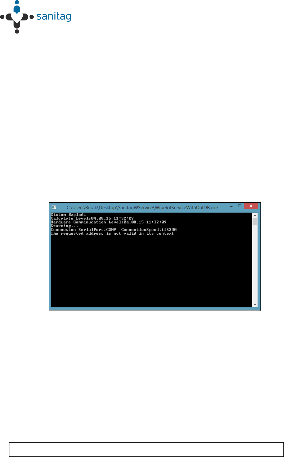
1. Run WipelotServiceManagerHealth.exe file from the Service Manager (Location
Provider Software). After this point, service manager screen will be opened as in
Figure 6.
Figure 6- Service Manager Screen (Disxonnected Network)
* Figure 6 implies that network is not connected. In the beginning of the same figure, serial port
and connection speed values can be seen.
2. In order to generate a network, room level readers and mobile devices are
activated. Some of them are illustrated in Figure 7, Figure 8, Figure 9.
Setting Up Devices & RF Netwowk
1-15
THIS DOCUMENT IS THE PROPERTY OF SANITAG COMPANY. IT MAY NOT BE COPIED AND REPRODUCED WITHOUT WRITTEN PERMISSION OF SANITAG
COMPANY. COPYRIGHT NOTICES MAY NOT BE REMOVED
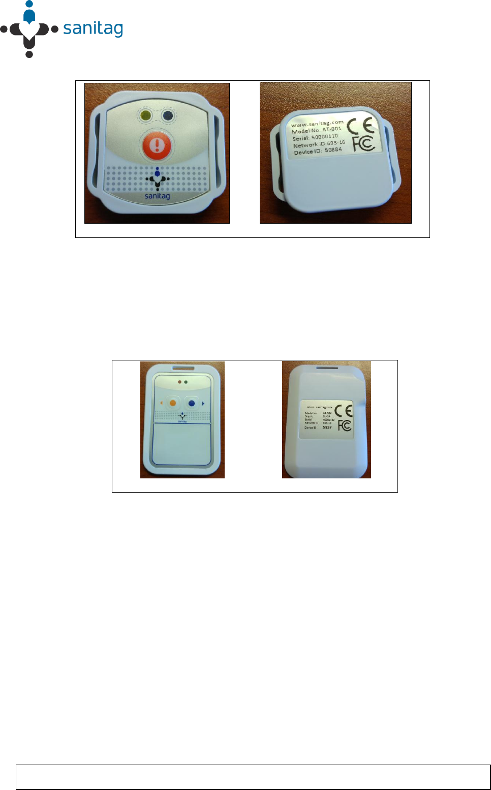
A B
Figure 7 - AT-001-H
* Figure 7 A- Front view of the AT-001-H type end device which is activated for the purpose of
the example
* Figure 7 B- Back view of the AT-001-H type end device which is activated for the purpose of
the example
A B
Figure 8 - AT-004-H
* Figure 8 A- Front view of the AT-004-H type end device(Badge Card) which is activated for
the purpose of the xample
* Figure 8 B- Back view of the AT-004-H type end device(Badge Card) which is activated for
the purpose of the example
Setting Up Devices & RF Netwowk
1-16
THIS DOCUMENT IS THE PROPERTY OF SANITAG COMPANY. IT MAY NOT BE COPIED AND REPRODUCED WITHOUT WRITTEN PERMISSION OF SANITAG
COMPANY. COPYRIGHT NOTICES MAY NOT BE REMOVED
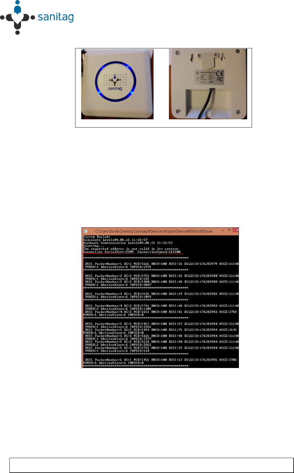
A B
Figure 9 - AC-001-LAN
* Figure 9.A Front view of the coordinator type device which is activated for the purpose of the
example
* Figure .9.B Front view of the coordinator type device which is activated for the purpose of the
example
3. After the activation of the devices network is constructed as can be seen in Figure
10. So this means that network information can be observed in Figure 10.
Figure 10 - Service manager screen(Connected network).
Setting Up Devices & RF Netwowk
1-17
THIS DOCUMENT IS THE PROPERTY OF SANITAG COMPANY. IT MAY NOT BE COPIED AND REPRODUCED WITHOUT WRITTEN PERMISSION OF SANITAG
COMPANY. COPYRIGHT NOTICES MAY NOT BE REMOVED
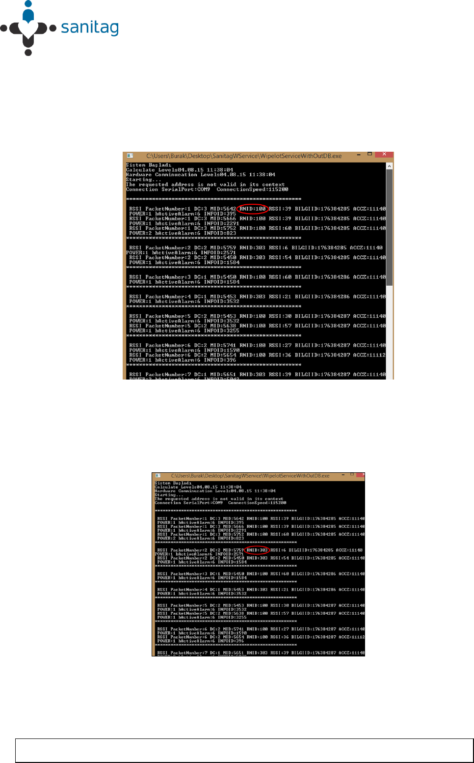
4. As can be seen from Figure- 9.B, Device ID of the reader is (which is coordinator)
100. In Figure 11, RNID number is circled where it is 100. So this means that
connection information of the router has been reached by the service manager.
RNID represents the reader identity number which is written to backside of every
reader device.
Figure 11-Service manager screen- 1(Reader is connected).
5. Then the second reader joined into the network with the device Id is equal to 303.
Thus service manager shows this device information on the screen as shown in
Figure 12 with a red circle. Note that the type of joined devices to the Rf network
are reader devices. Therefore RNID values are examined upto now.
Figure 12- Service manager screen -2
* Second reader is connected with device Id:303.
Setting Up Devices & RF Netwowk
1-18
THIS DOCUMENT IS THE PROPERTY OF SANITAG COMPANY. IT MAY NOT BE COPIED AND REPRODUCED WITHOUT WRITTEN PERMISSION OF SANITAG
COMPANY. COPYRIGHT NOTICES MAY NOT BE REMOVED
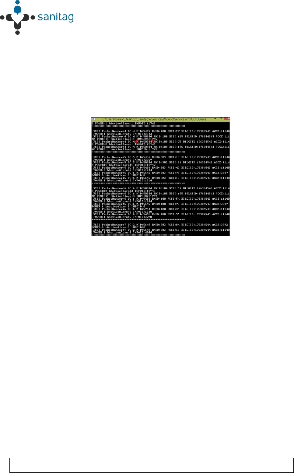
6. Now, the AT-001-H type of end device will be joined to the Rf network which is
shown in Figure 7. The device Id of the mobile device is 50884 as in Figure 7.B.
When this mobile device enters the Rf network, MID information has to be read in
order to see whether the mobile is connected to the network or not. In Figure 13,
this phenomena is illustrated. In this figure, mobile device had been joined to the
network with the MID:50884.Remark that the MID is the abbreviation of mobile
device identity.
Figure 13 - Service manager screen -3
* AT-001-H type mobile device is connected with device Id: 50884.
Setting Up Devices & RF Netwowk
1-19
THIS DOCUMENT IS THE PROPERTY OF SANITAG COMPANY. IT MAY NOT BE COPIED AND REPRODUCED WITHOUT WRITTEN PERMISSION OF SANITAG
COMPANY. COPYRIGHT NOTICES MAY NOT BE REMOVED
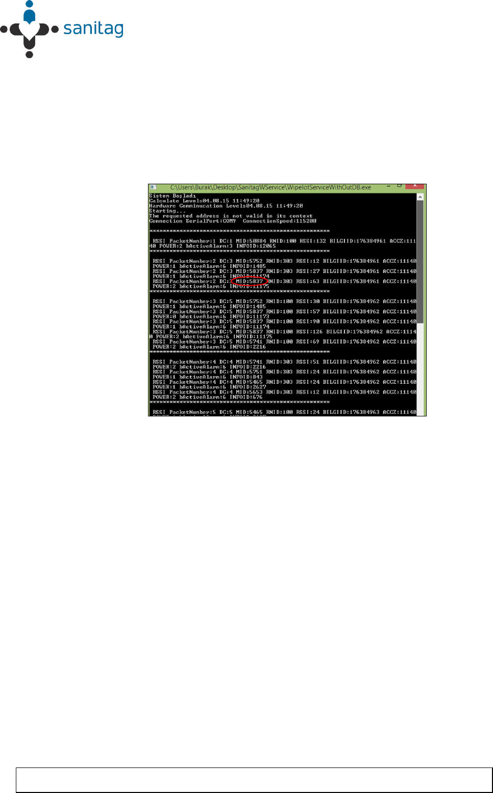
7. Finally, AT-004-H type of end device will be joined to the Rf network which is
shown in Figure 8.A. The device Id of the mobile device is 5837 as in Figure 8.B.
Since AT-004-H type of end device is a mobile device, MID information has to be
read in order to see whether the mobile is connected to the network or not.
As can be observed from the Figure 14, mobile device with MID: 5837 had been
entered to the network which is noticed with a red circle.
Figure 14 - Service manager screen -4
* Service manager screen - AT-004-H type mobile device is connected with device Id: 5837.

Setting Up Devices & RF Netwowk