Sanwa Electronic Instrument Co 90480 2.4GHz RADIO CONTROL SYSTEM User Manual
Sanwa Electronic Instrument Co Ltd 2.4GHz RADIO CONTROL SYSTEM
Users Manual

Page 1
Page 2
INTRODUCTION
We appreciate your purchase of the new Airtronics M11X FHSS 2.4GHz radio control system. This operating manual is intended
to acquaint you with the many unique features of your state of the art M11X FHSS 2.4GHz radio control system. Please read this
operating manual carefully so that you may obtain maximum success and enjoyment from the operation of your new M11X FHSS
2.4GHz radio control system.
The M11X FHSS 2.4GHz radio control system has been designed for the utmost in comfort and precise control of all types of
model cars and boats. We wish you the best of success and fun with your new purchase.
OBe certain to read this operating manual in its entirety.
O'Safety First' for yourself, for others, and for your equipment.
O 2EVHUYHDOOWKHUXOHVRIWKH¿HOGWUDFNRUODNHZKHUH\RX
operate your radio control equipment.
OIf at any time during the operation of your model, should
you feel or observe erratic operation or abnormality, end
\RXURSHUDWLRQDVTXLFNO\DQGVDIHO\DVSRVVLEOH'2127
operate your model again until you are certain the problem
KDVEHHQFRUUHFWHG7$.(12&+$1&(6
OYour model can cause serious damage or injury, so please
use caution and courtesy at all times.
This radio control system operates on the 2.4GHz frequency band. The 2.4GHz connection is determined by the transmitter
DQGUHFHLYHUSDLUWKHUHIRUHXQOLNHRUGLQDU\FU\VWDOV\VWHPV\RXUPRGHOFDQEHXVHGZLWKRXWIUHTXHQF\FRQWURO
Additional 2.4GHz receivers can be purchased and paired with the included 2.4GHz transmitter through the pairing operation.
Please note that due to differences in the implementation of 2.4GHz technology among different manufacturers, only Airtronics brand
2.4GHz FHSS receivers are compatible with your radio control system. Please see your Airtronics dealer for more information.
FCC COMPLIANCE STATEMENT
7KLVHTXLSPHQWKDVEHHQWHVWHGDQGIRXQGWRFRPSO\ZLWKWKHOLPLWVIRUD&ODVV%GLJLWDOGHYLFHSXUVXDQWWR3DUWRIWKH)&&
Rules. These limits are designed to provide reasonable protection against harmful interference in a residential installation. This
equipment generates, uses, and can radiate radio frequency energy and, if not installed and used in accordance with the
instructions, may cause harmful interference to radio communications. However, there is no guarantee that interference will not
occur in a particular installation.
If this equipment does cause harmful interference to radio or television reception, which can be determined by turning the
equipment off and on, the user is encouraged to try to correct the interference by one or more th the following measures:
OReorient or relocate the receiving antenna.
OIncrease the separation between the equipment and the receiver.
O&RQQHFWWKHHTXLSPHQWLQWRDQRXWOHWRQDFLUFXLWGLIIHUHQWIURPWKDWWRZKLFKWKHUHFHLYHULVFRQQHFWHG
O&RQVXOWWKHGHDOHURUDQH[SHULHQFHGWHFKQLFLDQIRUKHOS
7KLVGHYLFHFRPSOLHVZLWK3DUWRIWKH)&&5XOHVDQGZLWK566RI,QGXVWU\&DQDGD2SHUDWLRQLVVXEMHFWWRWKHIROORZLQJ
two conditions:
1) This device may not cause harmful interference, and
2) This device must accept any interference received, including interference that may cause undesired operation.
WARNING:&KDQJHVRUPRGL¿FDWLRQVPDGHWRWKLVHTXLSPHQWQRWH[SUHVVO\DSSURYHGE\$LUWURQLFVPD\YRLGWKH)&&DXWKRUL]DWLRQ
to operate this equipment.
RF Exposure Statement
7KLVWUDQVPLWWHUKDVEHHQWHVWHGDQGPHHWVWKH)&&5)H[SRVXUHJXLGOLQHVZKHQXVHGZLWKWKH$LUWURQLFVDFFHVVRULHVVXSSOLHG
RUGHVLJQDWLHGIRUWKLVSURGXFWDQGSURYLGHGDWOHDVWFPVHSDUDWLRQEHWZHHQWKHDQWHQQDWKHXVHUVERG\LVPLDLQWDLQHG8VH
RIRWKHUDFFHVVVRULHVPD\QRWHQVXUHFRPSOLDQFHZLWK)&&5)H[SRVXUHJXLGHOLQHV
O 'RQRWH[SRVHWKHUDGLRFRQWUROV\VWHPWRZDWHURUH[FHVVLYH
moisture.
OPlease waterproof the receiver and servos by placing them
LQDZDWHUWLJKWUDGLRER[ZKHQRSHUDWLQJ5&ERDWPRGHOV
O ,I\RXKDYHOLWWOHWRQRH[SHULHQFHRSHUDWLQJ5&PRGHOVZH
VWURQJO\UHFRPPHQG\RXVHHNWKHDVVLVWDQFHRIH[SHULHQFHG
modelers or your local hobby shop for guidance.
OThe low voltage alarm will sound when the transmitter battery
voltage drops to ~6.7 volts. If this occurs, stop using the
transmitter as soon as possible, then recharge the transmitter
battery.
SAFETY
Page 3
FEATURES AND SPECIFICATIONS
SYSTEM FEATURES
SYSTEM SPECIFICATIONS
O2.4GHz FHSS Transmitter and Receiver
O/DUJH/&''LVSOD\
OLeft or Right Hand Grip
O'LJLWDO7ULP
O.H\/RFN
O'LVSOD\6ZLWFK
OAdjustable Handle
OAdjustable Steering Wheel Tension
O3 Page Programming
OTimer Vibration
OBattery Monitor
O8VHU1DPLQJ
O$VVLJQDEOH'LJLWDO7ULPV
OAssignable Switches
OAudio Sound Levels
O:KLWHRU%OXH%DFN/LJKW'LVSOD\
OServo Monitor
O7ZHDN
O&0L[HV
O%UDNH0L[LQJ
OThrottle Hold
OStarting Position
OServo Reversing
O/DS,QWHUYDODQG'RZQ7LPHUV
OSub Trim
O0RGHO0HPRU\
O0RGHO&RS\
O0RGHO1DPLQJ
OModel Select
O7UDFWLRQ&RQWURO
O$QWL/RFN%UDNLQJ
OServo Speed
O$5&6WHHULQJDQG7KURWWOH
OExpo Steering and Throttle
OEnd Point Adjustment
O'XDO5DWH6WHHULQJ
O6HOHFWDEOH0RQLWRU'LVSOD\
ORubber Stands
O/&'&RYHU
O'LDO.QRE
OGrip Switch
ORU&KDQQHO6HOHFWDEOH
Transmitter
Model:
Output Power:
2XWSXW9ROWDJHYY
Power Supply:
Weight:
Frequency:
Receiver
Model:
Frequency:
Power Supply:
Weight:
'LPHQVLRQV
Fail Safe Limit:
5HFRPPHQGHG6HUYRV$YDLODEOH)URP<RXU/RFDO$LUWURQLFV'HDOHU
Airtonics 94771M ERG-WZ Digital High-Speed Metal Gear Ball Bearing Servo
Optional Items
7RUTXH R]LQNJFP#Y
R]LQNJFP#Y
6SHHG VHF#Y
VHF#Y
'LPHQVLRQV[[LQ[[PP
:HLJKWR]JU
7RUTXH R]LQNJFP#Y
R]LQNJFP#Y
6SHHG VHF#Y
VHF#Y
'LPHQVLRQV[[LQ[[PP
:HLJKWR]JU
Airtonics 94772M ERG-WG Digital High-Speed Precision Metal Gear Ball Bearing Servo
7RUTXH R]LQNJFP#Y
R]LQNJFP#Y
6SHHG VHF#Y
VHF#Y
'LPHQVLRQV[[LQ[[PP
:HLJKWR]JU
Airtonics 94773M ERG-WX Digital High-Torque Metal Gear Ball Bearing Servo
Both analog and digital servos
ZLOO ZRUN ZLWK \RXU 0; )+66
2.4GHz radio control system, however,
to get the most out of your experience,
we recommend the use of digital servos.
Page 4
DRIVING POSITION ADJUSTMENTS
STEERING WHEEL TENSION
Every effort has been made to provide optimum transmitter weight and balance on your M11X FHSS 2.4GHz radio control
system. The wheel and trigger are placed on the same axis, permitting you to focus on steering and throttle control. The driving
SRVLWLRQDQGVWHHULQJWKURWWOHWHQVLRQDUHDGMXVWDEOHWRPD[LPL]HGULYLQJSUHFLVLRQ
The steering wheel spring tension can be adjusted using a
PPKH[ZUHQFKDVVKRZQDWULJKW7RLQFUHDVHVWHHULQJ
ZKHHOVSULQJWHQVLRQWLJKWHQWKHKH[VFUHZWXUQFORFNZLVH
To decrease steering wheel spring tension loosen the hex
VFUHZWXUQFRXQWHUFORFNZLVH
DRIVING POSITION
The driving position height can be adjusted to change the
balance (feel) of the transmitter in your hand.
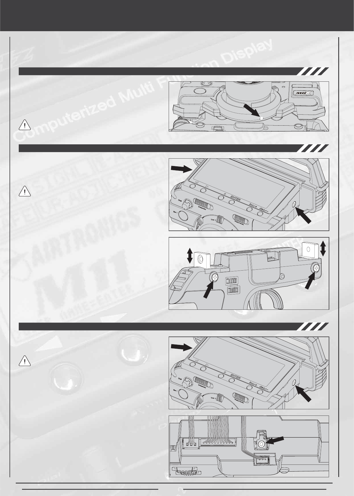
THROTTLE TRIGGER TENSION
The throttle trigger spring tension can be adjusted to suit
your taste.
The spring tension is factory set at the lowest (softest)
position.
5HPRYHWKH0VRFNHWKHDGFDSVFUHZVRQHDFKVLGH
of the transmitter using a 3mm hex wrench.
'HWDFK WKH JULS GRZQZDUG IURP WKH XSSHU WUDQVPLWWHU
unit. Be careful to avoid damaging the lead wires that
are connected on both units.
3) There are four phillips head screws holding each side
RIWKHJULSEUDFNHW5HPRYHWKHVFUHZVDQGUHVHWWKH
EUDFNHWVFUHZKROH DWWKHORZHU VFUHZ KROH7KLVVHWV
WKHEUDFNHWWRWKHKLJKHUKHLJKWSRVLWLRQ
4) After resetting the driving position, retighten the grip
EUDFNHW VFUHZV WKHQ DOLJQ WKH XSSHU WUDQVPLWWHU XQLW
DQGUHLQVWDOOLWXVLQJWKHWZR0VRFNHWKHDGFDSVFUHZV
7KHWUDQVPLWWHUVKLSVZLWKWKHJULSEUDFNHWLQWKHORZHU
height position.
5HPRYHWKH0VRFNHWKHDGFDSVFUHZVRQHDFKVLGH
of the transmitter using a 3mm hex wrench.
'HWDFK WKH JULS GRZQZDUG IURP WKH XSSHU WUDQVPLWWHU
unit. Be careful to avoid damaging the lead wires that
are connected on both units.
$GMXVW WKH WKURWWOH WULJJHU VSULQJ WHQVLRQ XVLQJ D
mm hex wrench as shown at right. To increase throttle
trigger spring tension tighten the hex screw (turn
FORFNZLVH7RGHFUHDVHWKURWWOHWULJJHU VSULQJWHQVLRQ
ORRVHQWKHKH[VFUHZWXUQFRXQWHUFORFNZLVH
4) After resetting the throttle trigger spring tension, align
the upper transmitter unit and reinstall it using the two
0VRFNHWKHDGFDSVFUHZV
The spring tension is factory set at the lowest (softest)
position.
3DJH
DRIVING POSITION ADJUSTMENTS
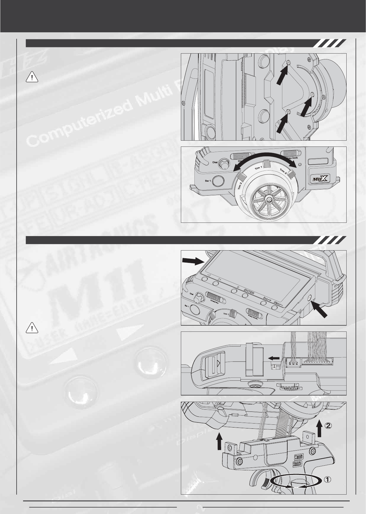
TRIM RING POSITION
The position of the digital trim ring can be repositioned to
better suit your taste. Five different positions are available.
Trm 1 is factory set at the top center position.
5HPRYHWKH0VRFNHWKHDGFDSVFUHZVRQHDFKVLGH
of the transmitter using a 3mm hex wrench.
'HWDFK WKH JULS GRZQZDUG IURP WKH XSSHU WUDQVPLWWHU
unit. Be careful to avoid damaging the lead wires that
are connected on both units.
5HPRYHWKHWKUHH0VRFNHWKHDGFDS VFUHZV IURP
WKH EDFNVLGH RI WKH WULP ULQJ LH EHKLQG WKH VWHHULQJ
wheel as shown on the photo) using a 2mm hex wrench.
4) Rotate the trim ring to the desired position. The trim
SULQJFDQEHSRVLWLRQHGLQRQHRI¿YHGLIIHUHQWSRVLWLRQV
Set the trim ring at the desired position, then retighten
WKHWKUHH0VRFNHWKHDGFDSVFUHZV
$IWHU UHVHWWLQJ WKH WULPPHU SRVLWLRQ DWWDFK WKH XSSHU
WUDQVPLWWHUXQLWEDFNLQWRSODFH7LJKWHQXVLQJDPP
KH[ ZUHQFK DQG WZR PP KH[ VRFNHW KHDG FDS
screws per side.
The steering wheel position can be changed from the right
VLGHWRWKHOHIWVLGHWRDFFRPRGDWHOHIWKDQGHGXVHUV
5HPRYHWKH0VRFNHWKHDGFDSVFUHZVRQHDFKVLGH
of the transmitter using a 3mm hex wrench.
'HWDFK WKH JULS GRZQZDUG IURP WKH XSSHU WUDQVPLWWHU
unit. Be careful to avoid damaging the lead wires that
are connected on both units.
6HW WKH /HIW5LJKW VHOHFWRU VZLWFK WR / ORFDWHG DERYH
7UPDQG7UP
5RWDWHWKHJULSE\GHJUHHV
$IWHU URWDWLQJ WKH JULS DOLJQ WKH XSSHU WUDQVPLWWHU XQLW
DQG UHLQVWDOO LW XVLQJ WKH WZR 0 VRFNHWKHDG FDS
screws.
The transmitter ships with the steering wheel on the
ULJKWVLGHRIWKHWUDQVPLWWHUIRUULJKWKDQGHGXVHUV
STEERING WHEEL POSITION

Page 6
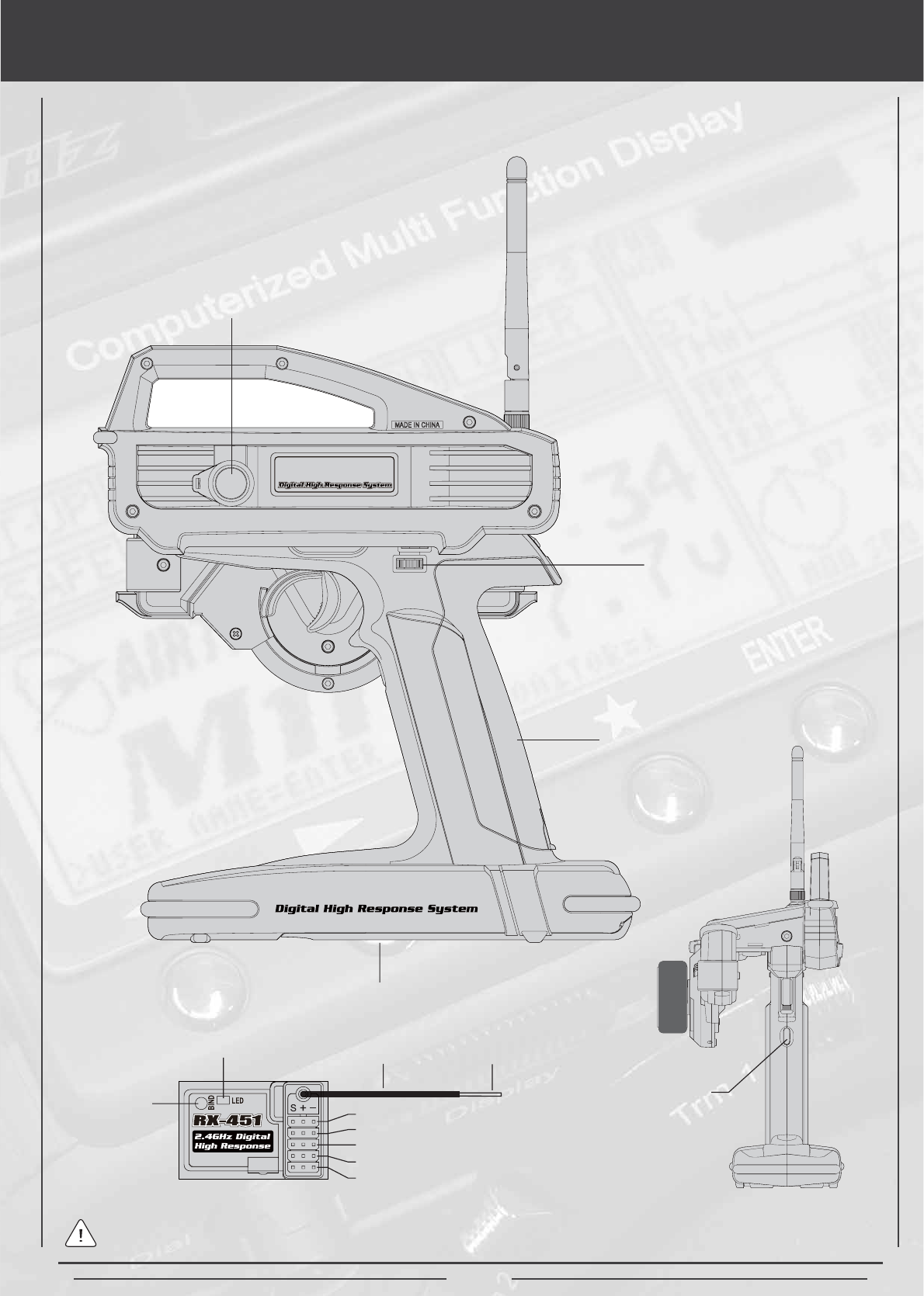
Features and Controls
Antenna
Power Switch
3XVK%XWWRQ
Switch (Sw 1)
&KDUJLQJ-DFN
'LVSOD\6ZLWFK
.H\/RFN6ZLWFK
Power Indicator
Light
7ULP&RQWURO
(Trm 2) 7ULP&RQWURO
(Trm 1)
7ULP&RQWURO
(Trm 3)
Steering Wheel
Strap Anchor
&KDUJLQJ-DFN
Power Switch
%DWWHU\'RRU
3XVK%XWWRQ
Switch (Sw 2)
3XVK%XWWRQ
Switch (Sw 2)
3XVK%XWWRQ
Switch (Sw3)
7ULP&RQWURO
(Trm 4)
7ULP&RQWURO
7UP
Trigger
/&'6FUHHQ
REAR
8VHWKHGLDJUDPVEHORZDQGRQWKHQH[WSDJHWRIDPLOLDUL]H\RXUVHOIZLWKWKHGLIIHUHQWIHDWXUHVDQGFRQWUROVRI\RXUQHZ0;
)+66*+]UDGLRFRQWUROV\VWHPWUDQVPLWWHUDQG5;UHFHLYHU
'LDO.QRE
Page 7
Features and Controls
'LUHFW6HUYR
&RQWURO-DFN'6&
7ULP&RQWURO
(Trm4)
%DWWHU\'RRU
3XVK%XWWRQ
Switch (Sw3)
FRONT
Grip
For more information about the terms used to describe the M11X FHSS 2.4GHz radio control system features, please refer
WRWKHJORVVDU\LQWKHEDFNRIWKLVRSHUDWLQJPDQXDO
Bind Key
%LQG/(' &RD[LDO&DEOH
Antenna
Reception Wire
%DWW'6&
$X[&K
$X[&K
7KURWWOH&K
6WHHULQJ&K
S = Signal
+ = Positive
1HJDWLYH
Page 8
usage precautions
TRANSMITTER PRECAUTIONS
Please observe the following receiver precautions when installing and using your new Airtronics M11X FHSS 2.4GHz radio
control system.
OThe receiver antenna consists of a coaxial cable and a reception wire (the thin tip at the end of the coaxial cable). When you
mount the receiver antenna, do not bend the reception wire. Reception performance decreases if the reception wire is bent.
O 7KHDQWHQQDZLUHLVGHOLFDWHWKHUHIRUHKDQGOHZLWKFDUH'RQRWSXOORQWKHDQWHQQDZLUHZLWKIRUFH'RQRWFXWRUH[WHQGWKH
antenna wire.
O 7KHFRD[LDOFDEOHWKHWKLFNHUSRUWLRQRUWKHDQWHQQDFDQEHEHQGLQWRJHQWOHFXUYHVKRZHYHUGRQRWEHQGWKHFRD[LDOFDEOH
accutely, or repeatedly bend it, or the antenna core can be damaged.
OThe antenna wire should be installed into a vertical plastic tube per your particular model's assembly instructions. Keep the
UHFHLYHUDQWHQQDDZD\IURPPRWRUVEDWWHU\DQG(6&
O 7KHUHLVDGDQJHURIUXQDZD\RSHUDWLRQLIFRQQHFWRUVVKDNHORRVHGXULQJXVH0DNHVXUHWKDWWKHUHFHLYHUVHUYRVDQGVZLWFK
FRQQHFWRUVDUHVHFXUHO\¿WWHG
O 7KH UHFHLYHU LV VXVFHSWLEOH WR YLEUDWLRQ VKRFN DQG PRLVWXUH7DNH DSSURSULDWH PHDVXUHV WR SURWHFW DJDLQVW YLEUDWLRQ DQG
PRLVWXUH)DLOXUHWRWDNHDSSURSULDWHPHDVXUHVFRXOGUHVXOWLQUXQDZD\RSHUDWLRQRUGDPDJHWRWKHUHFHLYHU
OWhen installing the receiver, avoid contact with any carbon or metal chassis components.
O &RQWDFWEHWZHHQPHWDOSDUWVPRXQWHGRQDPRGHOFDQUHVXOWLQHOHFWULFDOQRLVHZKLFKFDQDGYHUVHO\HIIHFWUHFHLYHUSHUIRUPDQFH
and possibly result in runaway operation or damage to your model.
O :LWKHOHFWULFSRZHUHGPRGHOVEHVXUHWR¿WWKHPRWRUZLWKDQRLVHVXSSUHVVLRQFDSDFLWRU:LWKRXWDQRLVHVXSSUHVVLRQFDSDFLWRU
H[FHVVLYHHOHFWULFDOQRLVHJHQHUDWLRQFDQFDXVHUXQDZD\RSHUDWLRQDQGRUUHVXOWLQGDPDJHWR\RXUPRGHO
O 8VHUXEEHUDQWLYLEUDWLRQDEVRUEHUVZLWKVHUYRV'LUHFWWUDQVPLVVLRQRIHQJLQHYLEUDWLRQWRVHUYRVFDQFDXVHVHUYRIDLOXUHDQG
possibly result in runaway operation with damag to your model vehicle.
OThe manufacturer disclaims all responsibility for damages resulting from use of components other than genuine Airtronics
components.
O 7XUQWKHWUDQVPLWWHU21¿UVWDQGWKHQWXUQ21WKHUHFHLYHU$IWHUXVLQJ\RXUPRGHOWXUQWKHUHFHLYHU2))¿UVWWKHQWXUQWKH
transmitter OFF. It can be dangerous if you activate the components in reverse order as the servos may start up inadvertantly.
O %HIRUHXVHGRXEOHFKHFNWKDWWKHWUDQVPLWWHUDQGUHFHLYHUEDWWHULHVDUHVXI¿FLHQWO\FKDUJHG
O 1HYHUWRXFKWKHWUDQVPLWWHUDQWHQQDGXULQJXVH'RLQJVRPD\FDXVHORVVRIWUDQVPLWWHURXWSXWPDNLQJLWLPSRVVLEOHWRFRQWURO
your model.
OThe transmitter's antenna is delicate. Handle it with care.
OBefore use, the transmitter antenna should be moved in the fully upright position. After use, to prevent the chance of damaging
the antenna, the antenna should be moved into the horizontal stowed position.
O 'RQRWSUHVVWKH%LQG.H\GXULQJXVH7KHUDGLRVLJQDOLVLQWHUUXSWHGZKLOHWKH%LQGNH\LVSUHVVHG,WPD\DOVRUHTXLUHDVKRUW
WLPHWRUHVWRUHWKHVLJQDODIWHUUHOHDVLQJWKH%LQGNH\ZKLFKFDQEHGDQJHURXV
RECEIVER PRECAUTIONS
2.4GHZ FREQUENCY BAND PRECAUTIONS
OThe 2.4GHz frequency band may be used by other devices, or other devices in the immediate area may cause interference on
the same frequency band. Always before use, conduct a bench test to ensure that the servos operate properly. Also, conduct
FKHFNVZLWKWKHWUDQVPLWWHUDVGLVWDQWDVSRVVLEOHIURP\RXUPRGHO
OThe response speed of the receiver can be affected if used where multiple 2.4GHz radio controllers are being use, therefore,
FDUHIXOO\FKHFNWKHDUHDEHIRUHXVH$OVRLIUHVSRQVHVHHPVVORZGXULQJXVHVWRS\RXUPRGHOLPPHGLDWHO\DQGVWRSXVH
OIf the 2.4GHz frequency band is saturated (too many radio controllers on at once), as a safety precaution, the radio control
system may not bind. This ensures that your radio control system does not get hit by interference. Once the frequencies have
been cleared, or the saturation level has dropped, your radio control system should be able to bind without any problems.
3DJH
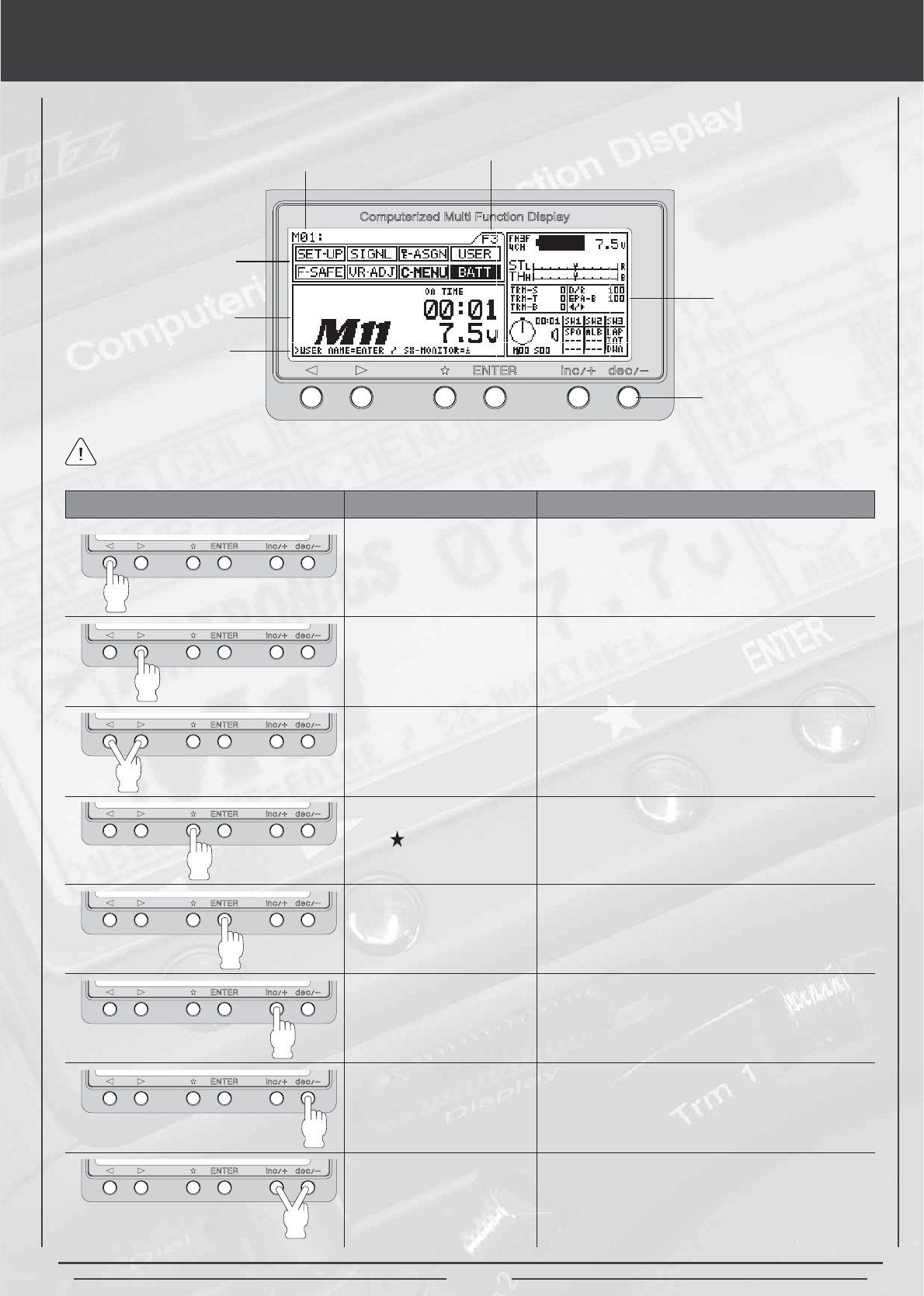
LCD Menu keys
7KH$LUWURQLFV0;)+66*+]UDGLRFRQWUROV\VWHPIHDWXUHVNH\VIRUPHQXRSHUDWLRQ7KLVVHFWLRQVXPPDUL]HVWKHIXQFWLRQV
RIHDFKRIWKHPHQXNH\VLQDGGLWLRQWRGHVFULELQJWKHPDLQGLVSOD\DUHDVRIWKH/&'VFUHHQZKHQWKHWUDQVPLWWHULVWXUQHGRQ
0RGHO1XPEHU
Menu Function
Programming
Window
+HOS'LVSOD\
Area
Key Pad
Information
Window
Function Page
)XQFWLRQ6HOHFW.H\/HIW 0RYHVWKH0HQX)XQFWLRQFXUVRUOHIWEDFNZDUG
to the previous menu function.
)XQFWLRQ6HOHFW.H\5LJKW Moves the Menu Function cursor right (forward)
to the next menu function.
Function Page Select
Key Sequence
3UHVVLQJERWKNH\VZLOOVFUROOWKURXJKWKH)XQFWLRQ
3DJHVLQRUGHU))DQG)7KH0HQX)XQFWLRQ
7KH&XUVRUZLOOKLJKOLJKWWKH¿UVWIXQFWLRQRQWKDW
page.
KEY NAME FUNCTION
Scroll Key 0RYHVWKH0HQX.H\EDFNZDUGLQWKH3URJUDPPLQJ
$UHD$OVRXVHGLQWKH+HOS'LVSOD\$UHD
Enter Key Moves the Menu Key forward in the Programming
$UHD$OVRXVHGLQWKH+HOS'LVSOD\$UHD
,1&.H\,QFUHDVH Increases number values in the Programming
Area. Also scrolls up the Selection List.
'(&.H\'HFUHDVH 'HFUHDVHV QXPEHU YDOXHV LQ WKH 3URJUDPPLQJ
Area. Also scrolls down the Selection List.
,1&DQG'(&5HVHW 3UHVVLQJERWKNH\VZLOO5HVHWWKHVHOHFWLRQWRWKH
)DFWRU\'HIDXOW6HWWLQJ
$SODVWLFFRYHULVLQFOXGHGWKDWVQDSVRYHUWKH/&'VFUHHQDQGNH\SDGWRSURWHFWLWGXULQJWUDYHORUVWRUDJH
3DJH
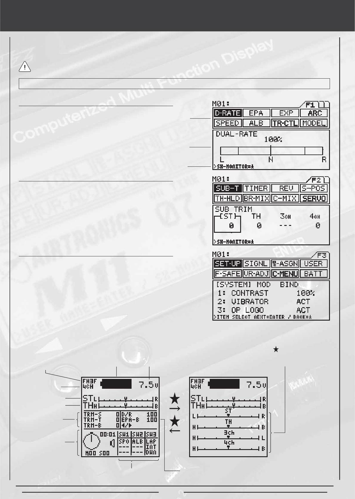
function pages
7KHIXQFWLRQVRIWKH0;)+66*+]UDGLRFRQWUROV\VWHPVSDQWKUHHSDJHV)WR)3UHVVLQJWKHDQG!IXQFWLRQNH\VDW
WKHVDPHWLPHGLVSOD\VHDFKRIWKHWKUHHIXQFWLRQSDJHVLQVXFFHVVLRQ))))HWF3UHVVLQJHLWKHUWKHRU!IXQFWLRQ
NH\VVHSDUDWHO\VFUROOVWKURXJKWKHLQGLYLGXDOIXQFWLRQVDVVLJQHGWRWKHIXQFWLRQSDJH\RXUHFXUUHQWO\YLHZLQJ
:KHQ\RXSUHVVHLWKHURIWKHPHQXNH\VWKH/&'EDFNOLJKWLQJZLOODXWRPDWLFDOO\WXUQRQ,IQRPHQXNH\LVSUHVVHGWKH
/&'EDFNOLJKWLQJZLOOWXUQRIIDIWHUDSSUR[LPDWHO\VHFRQGVWRFRQVHUYHEDWWHU\SRZHU
Function Menu F1 consists of the following individual functions:
O 'XDO5DWH
OEnd Point Adjustment
OExponential
O$GMXVWDEOH5DWH&RQWURO
OSteering Speed
O$QWL/RFN%UDNLQJ
O7UDFWLRQ&RQWURO
OModel
Function Menu F2 consists of the following individual functions:
O 6XE7ULP
OTimer
OServo Reversing
OStart Position
OThrottle Hold
O%UDNH0L[LQJ
O&RPSHQVDWLRQ0L[LQJ
OServo Monitor
Function Menu F3 consists of the following individual functions:
OTransmitter Setup
OAudio Signal Sound
O6ZLWFK7ULP$VVLJQPHQW
O8VHU1DPH
O)DLO6DIH6HWXS
O95$GMXVWPHQW0HQX
O&XVWRPHU0HQX
O%DWWHU\'LVSOD\0HQX
7KHFRQVWDQWGLVSOD\DUHDGHVFULEHGEHORZLVSURYLGHGRQWKHULJKWVLGHRIWKHVFUHHQ7KLVPDNHVLWSRVVLEOHWRGHWHUPLQHDWD
glance, the current setting status of various functions from any menu screen.
Menu Function
Programming Area
+HOS'LVSOD\$UHD
Timer
Information
Switch Status
Battery
Remaining
Battery
Voltage
Encoding Type
1XPEHURI
&KDQQHOV
Steering Trim
Throttle Trim
Trim Feature
Settings
'XDO5DWH%UDNH(3$
DQG&+6HWWLQJV
3UHVVLQJWKHNH\TXLFNO\VZLWFKHV
between the information screen and
the servo monitor screen.
All of the functions listed below are detailed in their own separate sections throughout this operating manual.
Page 11
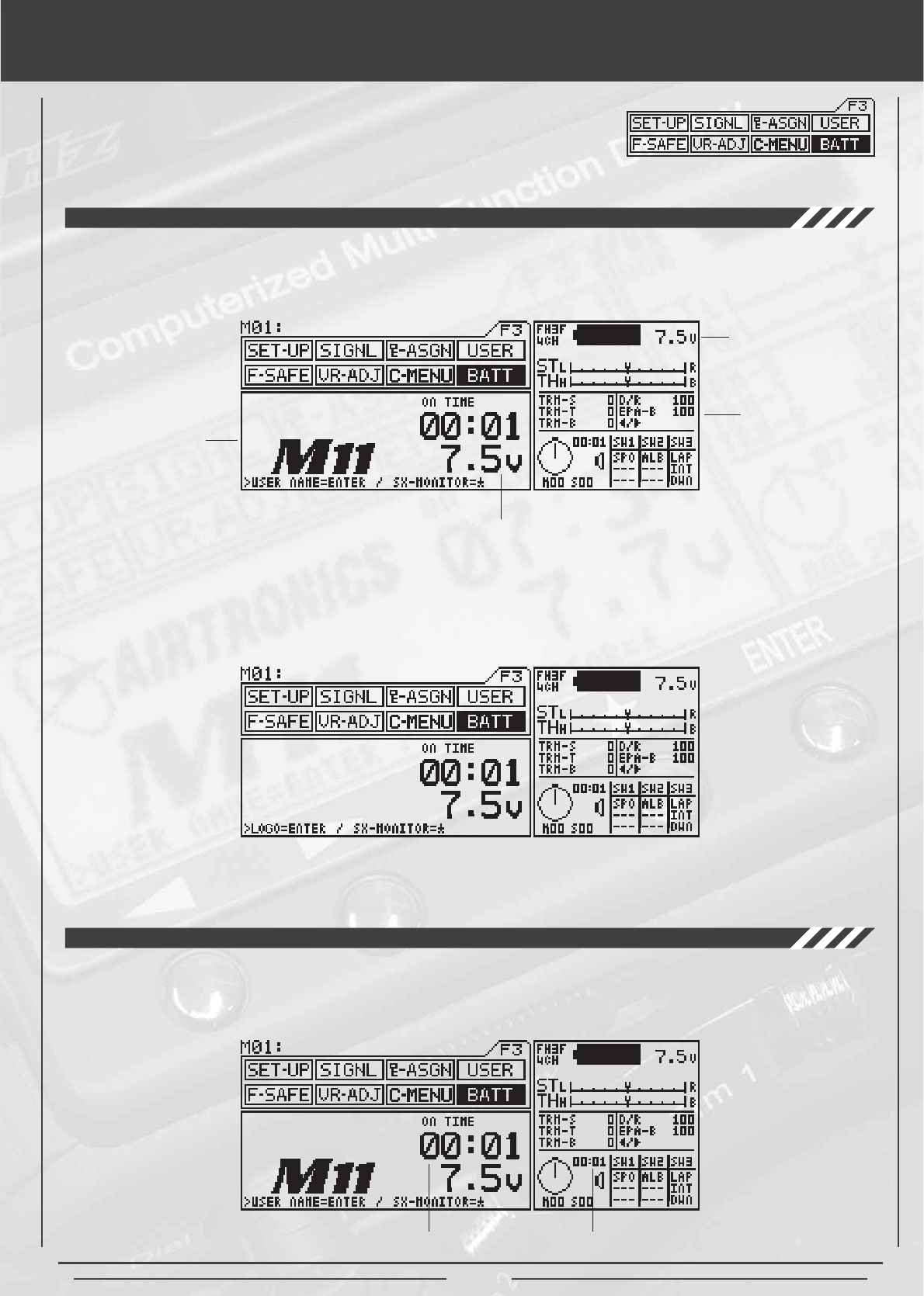
battery and operATING timer
Function Page 3 (BATT)
7KHWUDQVPLWWHUEDWWHU\YROWDJHLVGLVSOD\HGRQWZRGLIIHUHQWDUHDVRIWKH/&'VFUHHQ7UDQVPLWWHUEDWWHU\YROWDJHLVGLVSOD\HGLQ
the information window and in the battery menu window. Transmitter battery voltage is displayed in decimal value in increments
RIYROWV
Battery Voltage
Battery Voltage*
Programming
Window
When the transmitter battery voltage drops to 6.7 volts, the transmitter will start beeping and vibrating (if the vibration feature is
HQDEOHGDQGZLOOFRQWLQXHHYHU\VHFRQGV:KHQWKLVKDSSHQVSURPSWO\VWRSRSHUDWLRQDQGFKDUJHRUUHSODFHWKHWUDQVPLWWHU
EDWWHULHV&RQWLQXLQJWRXVHWKHWUDQVPLWWHUDIWHUWKHORZYROWDJHDODUPVRXQGVFDQUHVXOWLQORVVRIFRQWURORI\RXUPRGHO
*Will start blinking if battery voltage reaches 6.7 volts.
TRANSMITTER BATTERY VOLTAGE
OPERATING TIMER
7KHRSHUDWLQJWLPHULVDFRXQWXSWLPHUWKDWUHFRUGVWKHWLPHWKHWUDQVPLWWHUKDVEHHQWXUQHGRQLQKRXUVDQGPLQXWHV7KLVWLPHU
FDQEHUHVHWWRE\SUHVVLQJERWKWKH,1&'(&NH\VDWWKHVDPHWLPH5HVHWWLQJWKHRSHUDWLQJWLPHUDIWHU\RXKDYH
charged or replaced the transmitter battery will give you the amount of time the current battery has been in use.
Information
Window
Operation Timer Operation Timer
,QWKH%$77PHQX\RXFDQSUHVVWKH(17(5NH\WRVZLWFKEHWZHHQWKH/RJRVFUHHQDQGWKH8VHUVFUHHQ
Logo Screen
User Screen

Page 12