Sanwa Electronic Instrument Co 93024 2.4GHz RADIO CONTROL SYSTEM User Manual
Sanwa Electronic Instrument Co Ltd 2.4GHz RADIO CONTROL SYSTEM Users Manual
Users Manual
STYLUS
receiver information
FHSS Module
Airtronics 2.4GHz FHSS receivers can be purchased and paired with your Stylus 2.4GHz FHSS module-equipped transmitter through
the Binding operation. Please note that due to differences in the implementation of 2.4GHz technology among different manufacturers,
only Airtronics brand 2.4GHz FHSS aircraft receivers are compatible with the Stylus 2.4GHz FHSS module.
The following receivers are compatible with the Stylus 2.4GHz FHSS module:
92824 8-Channel 2.4GHz FHSS
92674 7-Channel 2.4GHz FHSS
92664 6-Channel Micro 2.4GHz FHSS
2.4GHz frequency Band Precautions
l The 2.4GHz frequency band may be used by other devices, or other devices in the immediate area may cause interference on the
same frequency band. Always before use, conduct a bench test to ensure that the servos operate properly. Also, conduct a range
test at the area of operation to ensure that the radio control system has complete control of the model at the farthest reaches of the
operational area.
l The response speed of the receiver can be affected if used where multiple 2.4GHz radio control systems are being used; therefore,
carefully check the area before use. Also, if response seems slow during use, discontinue use as quickly as possible.
l If the 2.4GHz frequency band is saturated (too many radio controllers on at once), as a safety precaution, the radio control system
may not bind. This ensures that your radio control system does not get hit by interference. Once the frequencies have been cleared,
or the saturation level has dropped, your radio control system should be able to bind without any problems.
l Observeanyapplicablelawsandregulationsinplaceatyouryingsitewhenusingthe2.4GHzradiocontrolsystem.
l Unlike frequency bands used with earlier radio control systems, reception with this 2.4GHz radio control system can be adversely
affected by large obstructions and concrete or steel structures between your model and the transmitter. Also, wire mesh and similar
barriers can adversely affect operation. Keep this mind to ensure the safety of your model.
This module operates on the 2.4GHz frequency band. The 2.4GHz connection is determined by the transmitter and receiver pair.
Unlike ordinary crystal-based systems, your model can be used without frequency control.
l Be certain to read this Operating Manual in its entirety.
l 'Safety First' for yourself, for others, and for your equipment.
l Observealltherulesoftheyingsiteoranywhereyouoperateyourradiocontrolequipment.
l If at any time during the operation of your model should you feel or observe erratic operation or abnormality, end your operation as
quickly and safely as possible. DO NOT operate your model again until you are certain the problem has been corrected.
l Your model can cause serious damage or injury, so please use caution and courtesy at all times.
l If you have little to no experience operating models, we strongly recommend you seek the assistance of experienced modelers or your
local hobby shop for guidance.
safety
Convert your Stylus transmitter to 2.4GHz FHSS Spread Spectrum technology with this high-quality module and antenna set. It is quick
and easy to install and allows you to easily switch back to 72MHz in less than a minute! Requires an Airtronics 2.4GHz FHSS receiver
(not included). For a list of compatible receivers, see the Receiver Information section below.
The Stylus 2.4GHz FHSS module is not compatible with the Airtronics 92104
10-Channel 2.4GHz FHSS-3 receiver from the SD-10G.
Bind Button
Coaxial Cables
Antenna
Reception
Wires
Bind Button
Bind LED
Bind LED
2.4GHZ MODULE INSTALLATION
Installing the 2.4GHz module and antenna onto your Stylus transmitter only takes a few minutes. To install the 2.4GHz module and
antenna, follow the steps below:
1)Carefullyremovetheexistingmodulefromthebackofyourtransmitter.Toremovethemodule,firml squeezethetwotabsonthe
sides of the module and pull the module straight out.
2) Remove the existing antenna from your transmitter. To remove the antenna, carefully unscrew the antenna (turn counter-clockwise)
from the antenna mount.
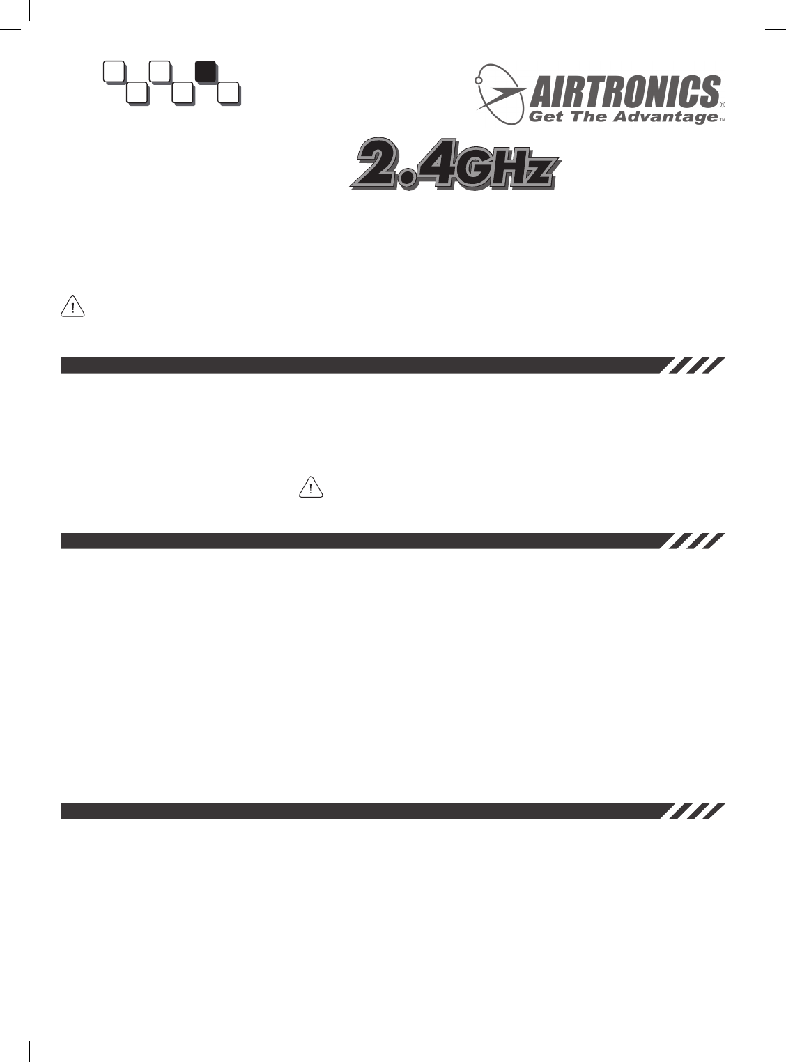
3) Install the 2.4GHz antenna mount (A) into the top of the transmitter. Tighten the
antenna mount snugly by hand.
4) Slide the 2.4GHz antenna adapter mount (B) between the handle and the top of the
transmitter, then place the antenna adapter mount over the antenna mount.
5) Rotate the antenna adapter mount so that the grub screw in the side of the
antenna adapter mount is toward the right side of the transmitter, then tighten the
grub screw, using a 1.5mm hex wrench.
6) Push the 2.4GHz module into the back of the transmitter, making sure to line the
moduleupcarefullytoavoiddamagingthepins.Pushthemodulefirml intoplace
to ensure that it’s seated fully. The tabs in the sides of the module will 'snap' into
place when installed correctly.
A
B
TRANSMITTER PRECAUTIONS
l Turn the transmitterONfirs andthenturnthereceiver ON. After using your model, turn the receiverOFFfirst thenturnthetransmitter
OFF. It can be dangerous if you activate the components in reverse order as the servos may start up inadvertently.
l Before use, double-check that the transmitter and receiverbatteriesaresufficientl charged.
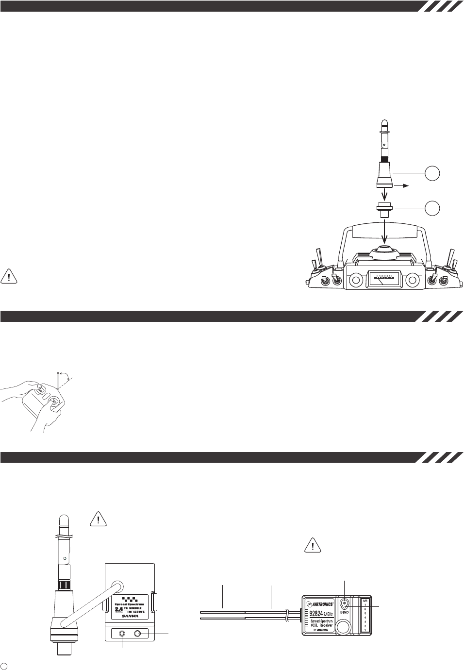
l Never touch the transmitter antenna during use. Doing so may cause loss of transmitter output, making it impossible
to control your model.
l Before use, the transmitter antenna should be angled so that the antenna is as close to perpendicular to the
ground as possible during use. This is the optimum angle for use. After use, to prevent any chance of damaging
the antenna, the antenna should be moved into the horizontal stowed position.
Keep Antenna
Perpendicular
to Ground
After being tightened, the antenna can be rotated right and left. During use,
the antenna should be rotated so that it can be angled back toward you. See the
Transmitter Precautions section below.
TRANSMITTER AND RECEIVER BINDING
It is necessary to pair the transmitter and receiver to prevent interference from radio controllers operated by other users. This operation
is referred to as 'binding'. Once the binding process is complete, the setting is remembered even when the transmitter and receiver are
turned OFF; therefore, this procedure usually only needs to be done once for each separate receiver you're using.
Airtronics 92824 RDS8000 8-Channel 2.4GHz FHSS receiver shown. The binding procedure for other
compatible Airtronics 2.4GHz receivers will be the same.
Grub Screw Toward Right.
When using the 2.4GHz FHSS module,
the Stylus' RF Meter will not function.
This is normal.
2
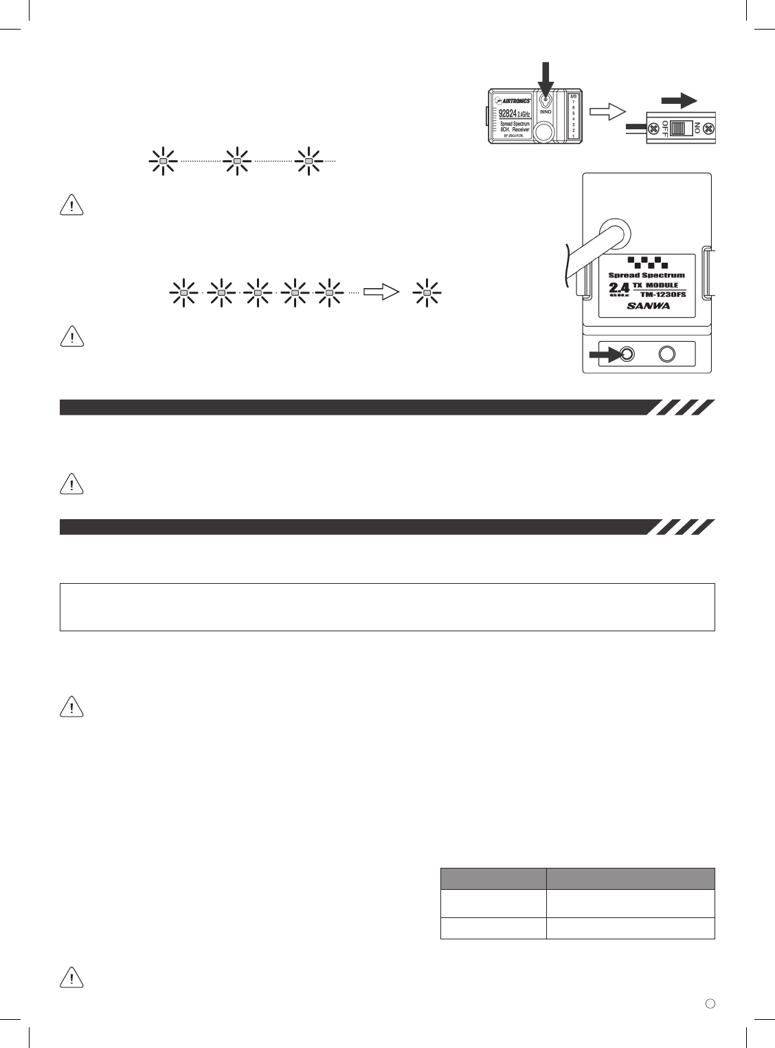
When the binding procedure is successful, the Bind LED on the receiver will stay solid blue
when both the transmitter and receiver are turned ON. If the Bind LED on the receiver is blinking
rapidly or not ON at all, the transmitter and receiver are not paired. In this case, turn both the transmitter
and receiver OFF, then repeat the binding procedure.
1) Turn the transmitter ON. The Bind LED on the module will illuminate solid blue.
3) Quickly press the Bind Button on the module. The Bind LED on the receiver will blink rapidly for ~ 3
seconds, go out momentarily, then illuminate solid blue, indicating the binding process is complete.
Use the tip of a pencil or a 1.5mm hex wrench to press the Bind Button on
the receiver.
2) While holding down the Bind Button on the receiver, turn the receiver ON. The
Bind LED on the receiver will blink slowly. After ~ 2 seconds release the Bind
Button. The Bind LED on the receiver will continue to blink slowly.
mountinG tHe receiver
Please refer to the separate instruction sheet included with your receiver for mounting instructions. If you’re using a 92824 or a 92674
receiver that utilizes dual antenna wires, pay careful attention to how you’re instructed to mount the antenna wires in your model.
Failure to mount the antenna wires as instructed can result in poor reception, or in some cases, complete loss of reception.
We recommend that you bind the transmitter and receiver prior to mounting the receiver into your model.
ranGe cHeckinG - low Power mode
The Stylus 2.4GHz FHSS module features a Low Power Mode function which lowers the transmitter's RF output level to check radio
signalreception.Usethisfunctiontocheckradiosignalreceptionontheground,priortoight.
IMPORTANTTheradiocontrolsystemshouldberangecheckedpriortotheday'srstightandpriortotherstightafterahard
landingorafterarepair.Thiswillensurethatthetransmitterandreceiverarecommunicatingproperlypriortoight.Thisensuresthe
safety of your model, yourself, and the people around you.
1) Press and hold the Bind Button on the module, then turn the transmitter ON. Continue to hold down the Bind Button for ~ 5 seconds.
The Bind LED will blink slowly during this time. After ~ 5 seconds the Bind LED will blink rapidly, then go out. Release the Bind Button
and the Bind LED will continuously blink rapidly. The transmitter is now in Low Power Mode.
Do not attempt to fly with the transmitter in Low Power
Mode. You will be unable to control your model once it is a
certain distance away from you. Before you fly, make sure
that the Bind LED is illuminated solid blue!
If, after checking all airborne system components and verifying correct antenna wire mounting, your radio control system still fails
the Range Check, DO NOT FLY. Please contact Airtronics Customer Service.
The transmitter will stay in Low Power Mode for 3 minutes. After 3 minutes, the transmitter will revert to Normal mode.
2) Turn the receiver ON in your model.
3) With the transmitter in Low Power Mode, walk approximately 30 paces from your model (approximately 90 feet) and, with the help
of another person, check to make sure that the servos move without any problems. If there is a problem with servo movement, try
moving to a different position while still maintaining the same distance from your model, then check servo movement again. If there
is still a problem, DO NOT FLY. Check to make sure that all receiver, servos, switch, and onboard battery connections are correct
and secure. Check to ensure that the antenna wires are correctly mounted.
4) After you have completed your range check, turn the transmitter OFF, then turn the transmitter ON to revert back to Normal Mode.
Low Power Mode
Normal Mode
POWER MODE MODULE BIND LED STATUS
Blue - Blinking Rapidly
Blue - Illuminated Solid
3

This equipment has been tested and found to comply with the limits for a Class B digital
device, pursuant to Part 15 of the FCC Rules. These limits are designed to provide
reasonable protection against harmful interference in a residential installation. This
equipment generates, uses, and can radiate radio frequency energy and, if not installed
and used in accordance with the instrucitons, may cause harmful interference to radio
communications. However, there is no gurantee that interference will not occur in a
particular installation.
If this equipment does cuase harmful interference to radio or television reception, which
can be determined by turning the equipment off and on, the user is envouraged to try to
correct the interference by one or more the of the following measures:
- reorient or relocate the receiving antenna.
- increase the separation between the equipment and the receiver.
- connect the equipment into an outlet on a circuit different from that to which the
receiver is connected.
- consult the dealer or an experienced technician for help.
This device complies with Part 15 of the FCC Rules and with RSS-210 of Industry
Canada. Operation is subject to the following two conditions:
1) this device may not cause harmful interference, and
2) this device must accept any interference received, including interference that may
cause undesired operation.
WARNING: Changes or modifications not expressly approved by Airtronics could void
the user’s authority to operate the equipment.
FCC COMPLIANCE STATEMENT