Sanyo Electric Co NPM-2000-C310 NPM-2000 Wireless Base Station User Manual NPM2 Installation Procedures 1600 mmds NPM2

Sanyo Electric Co Ltd NPM-2000 Wireless Base Station NPM2 Installation Procedures 1600 mmds NPM2

Contents

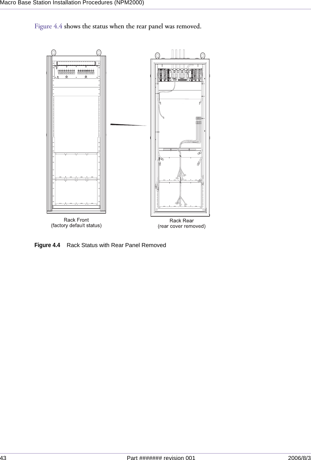
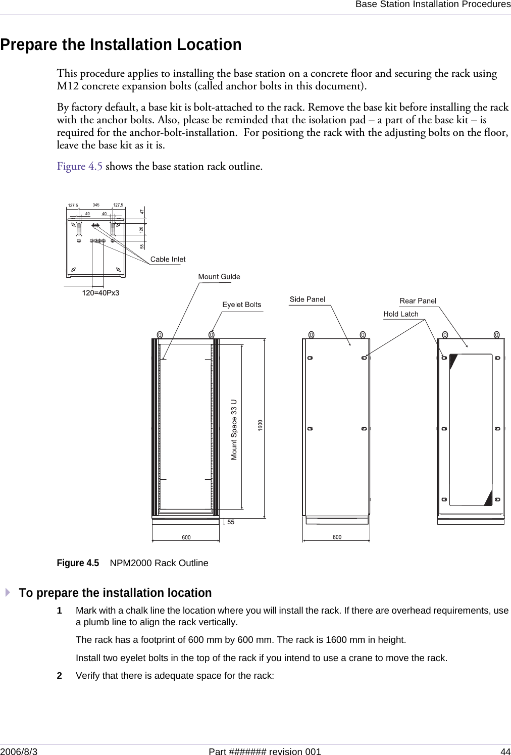
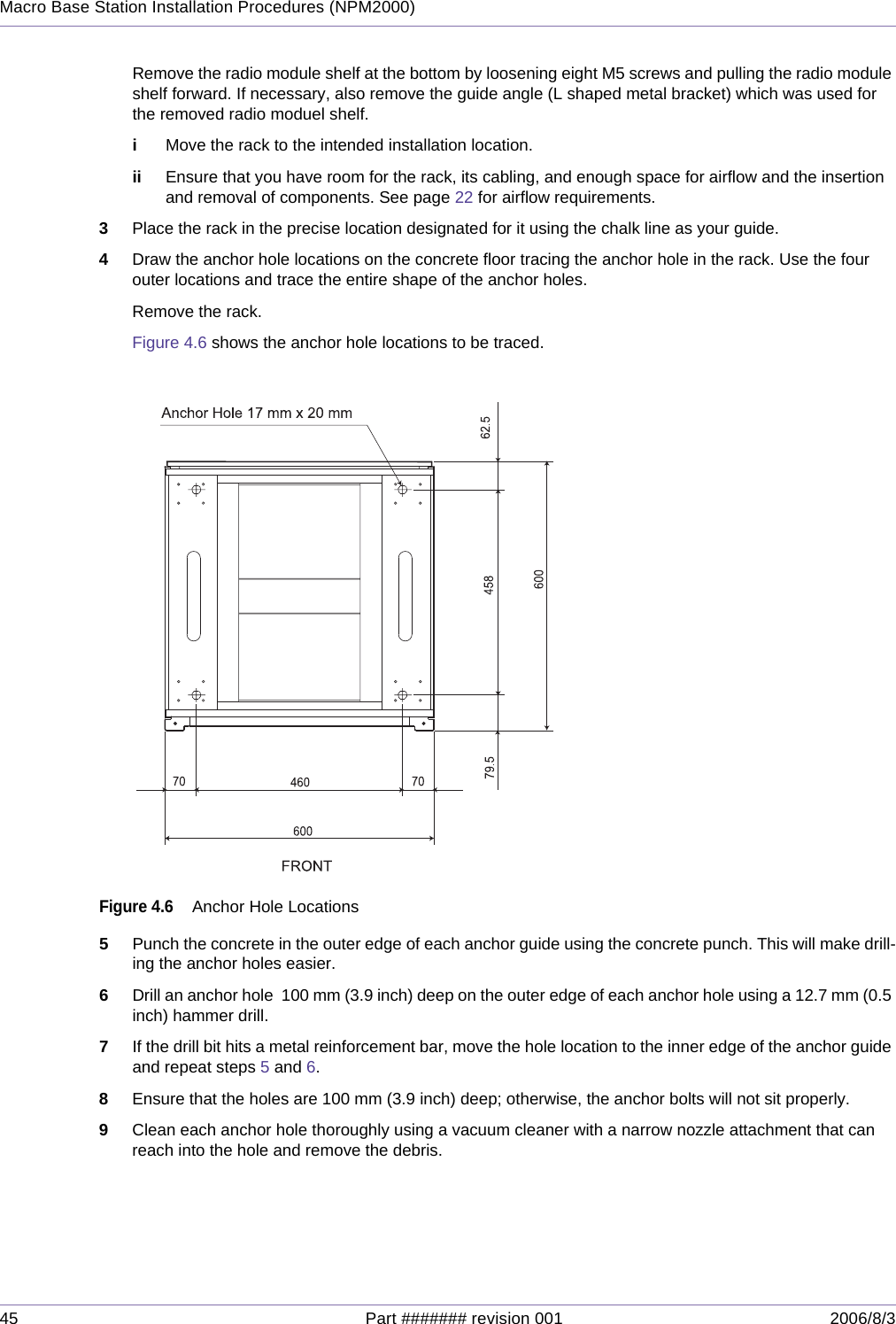
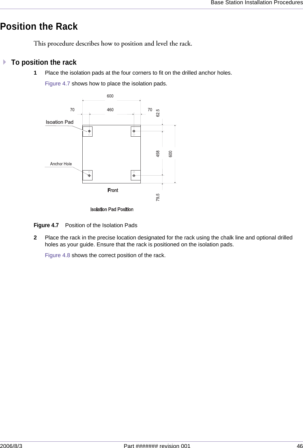
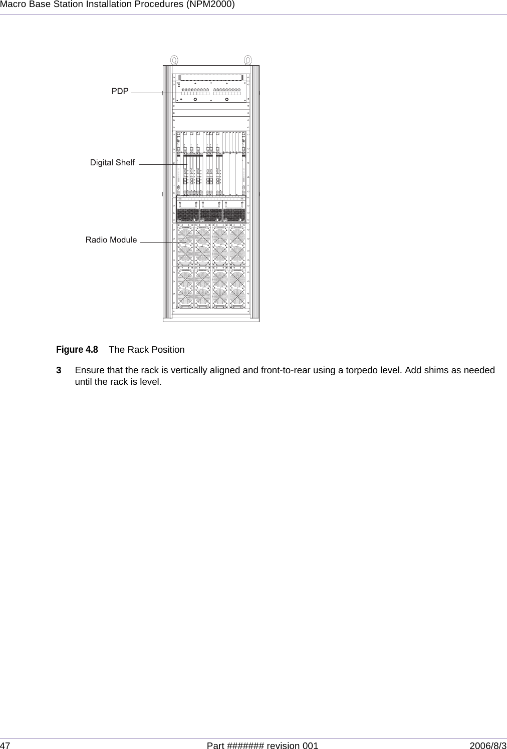
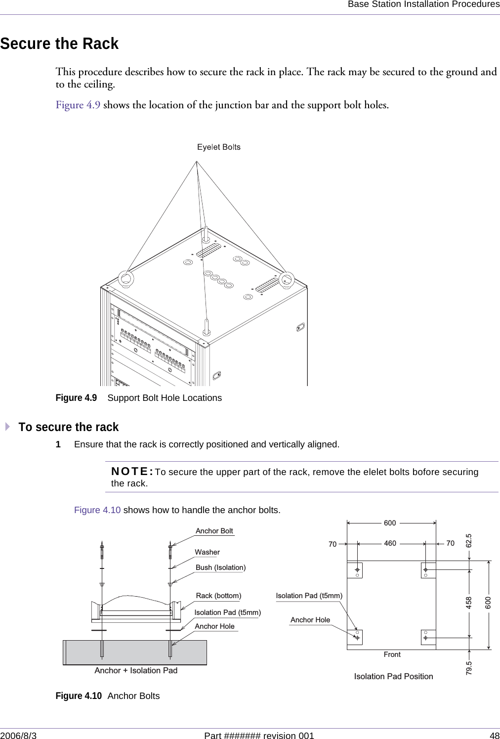
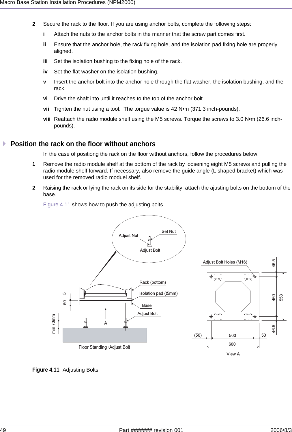
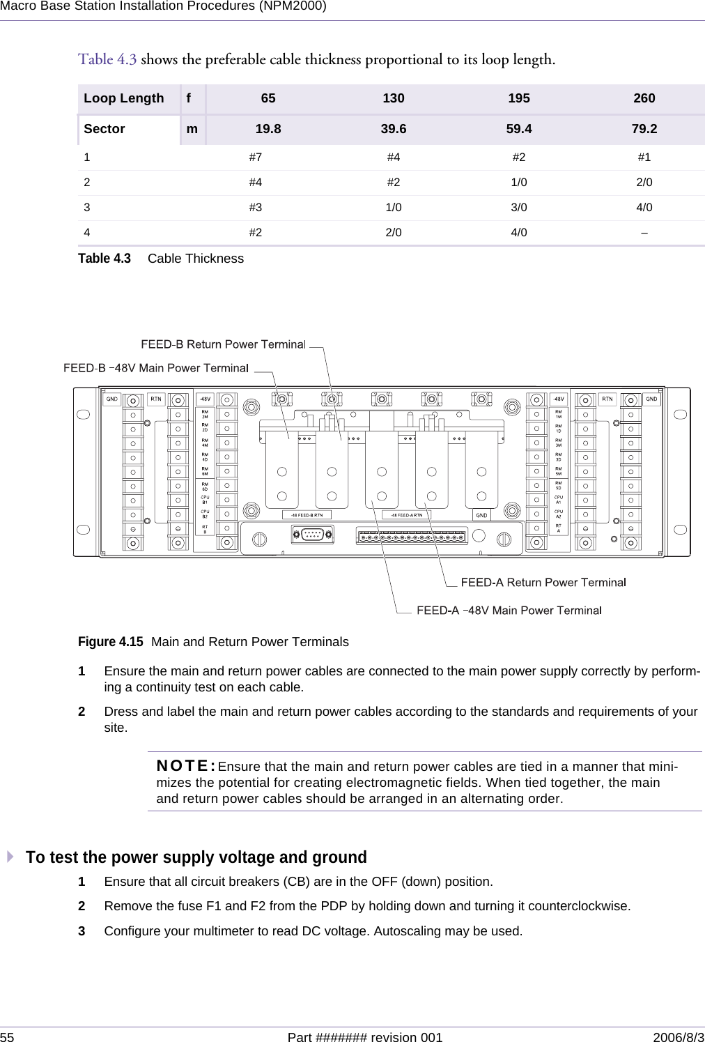
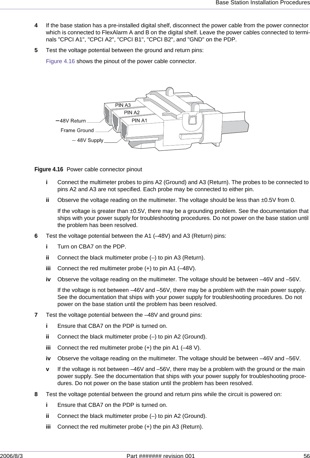
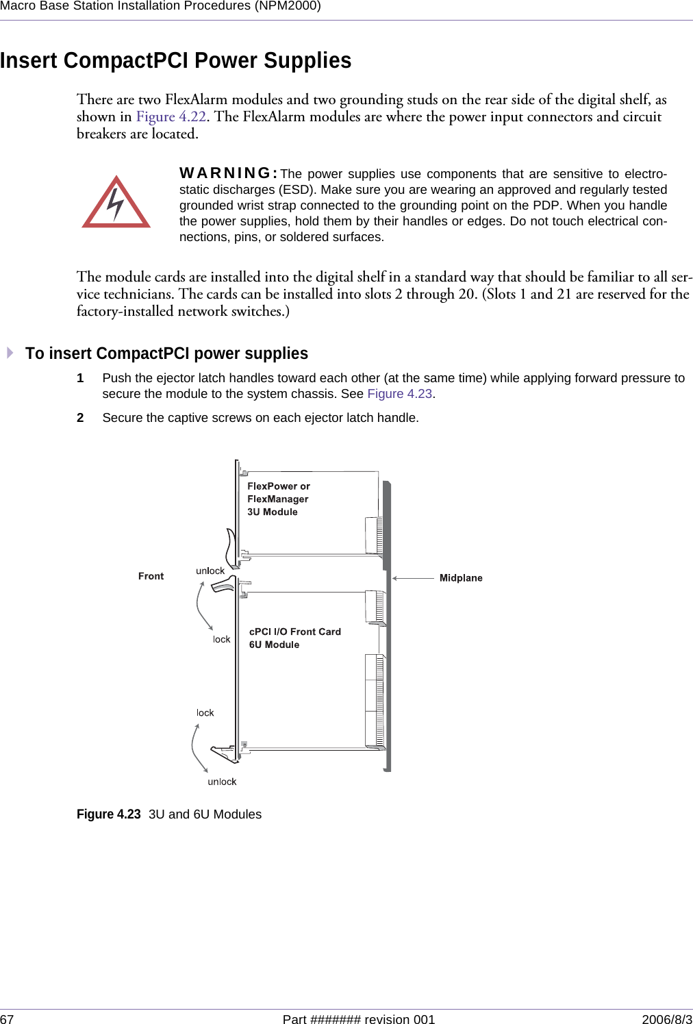
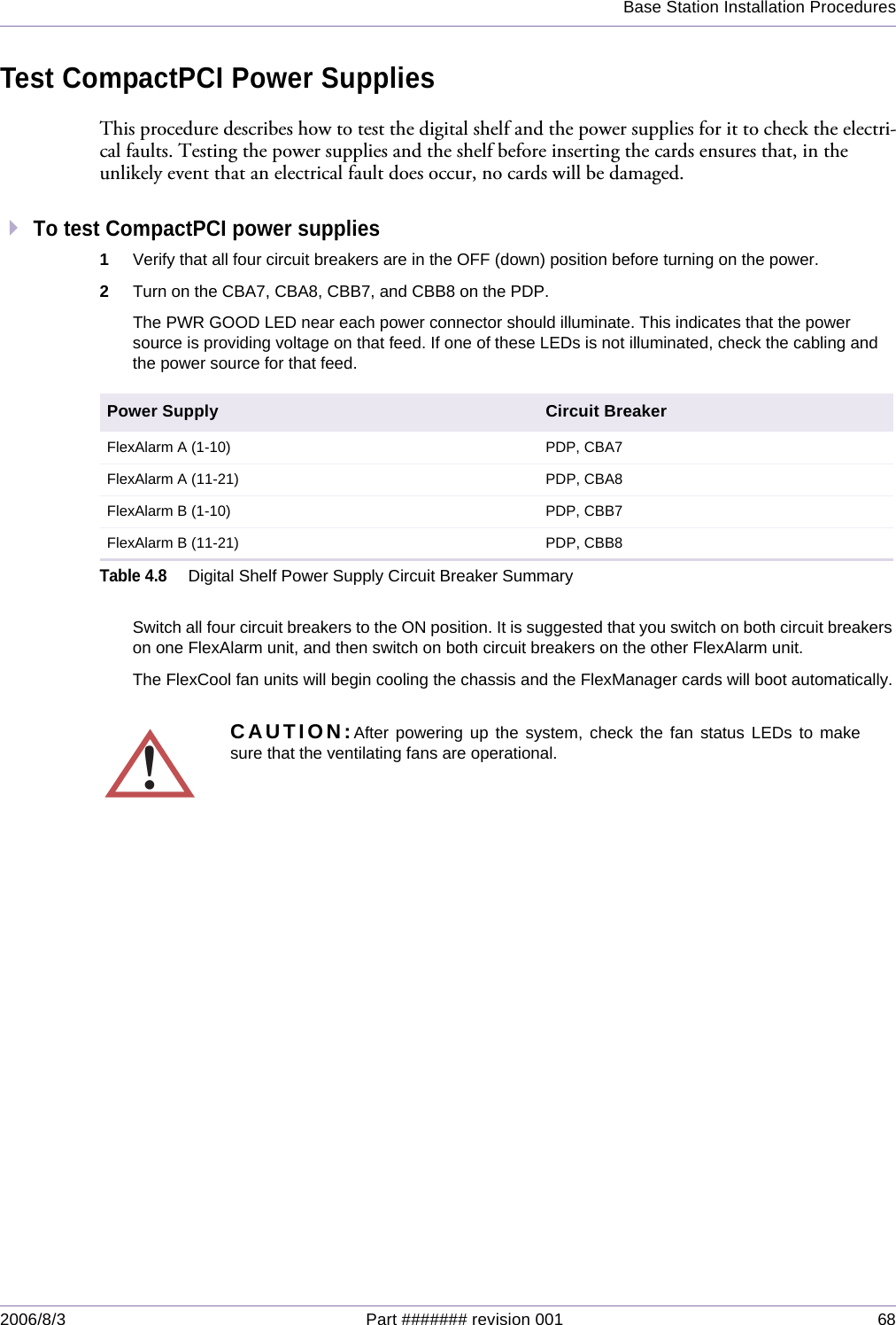
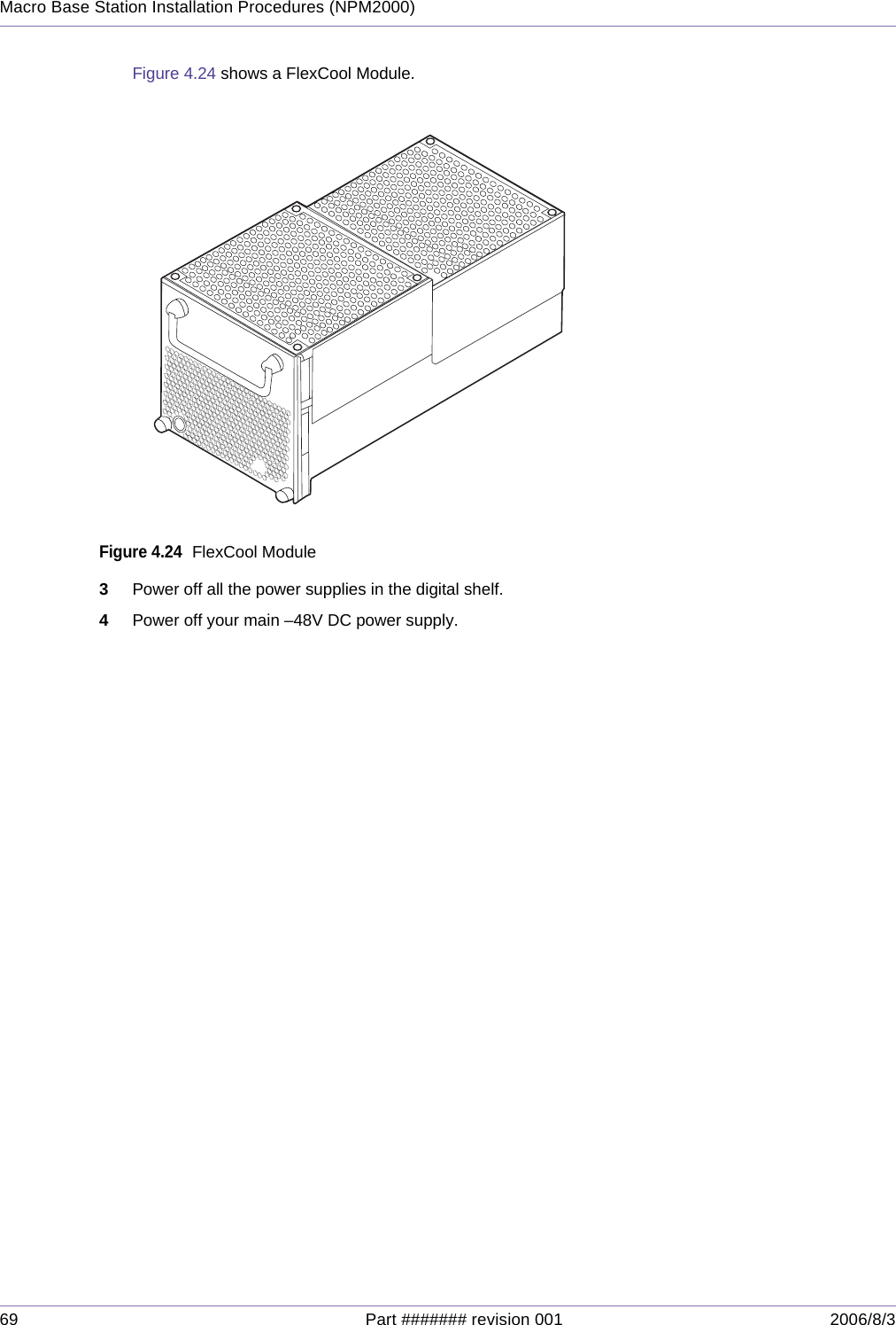
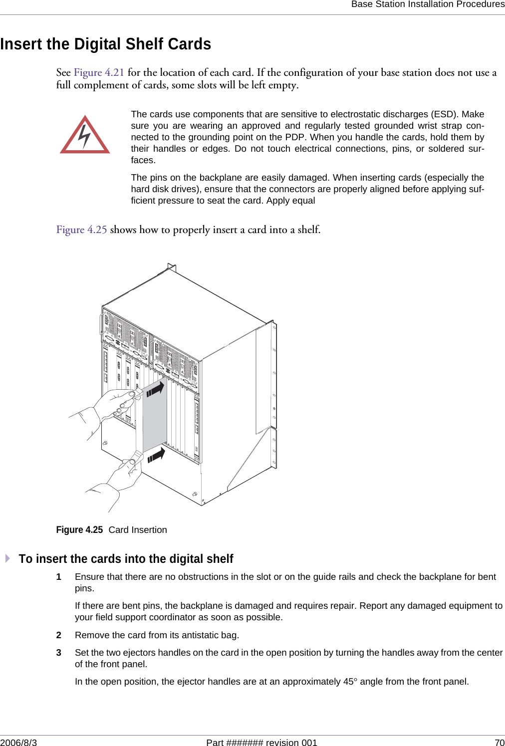
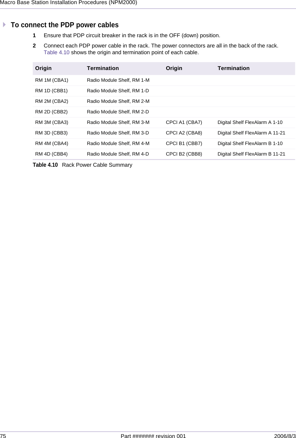
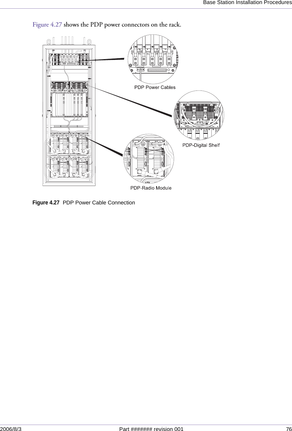
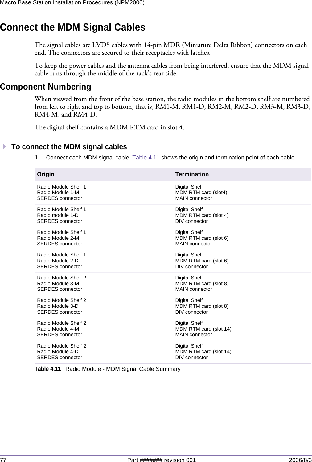
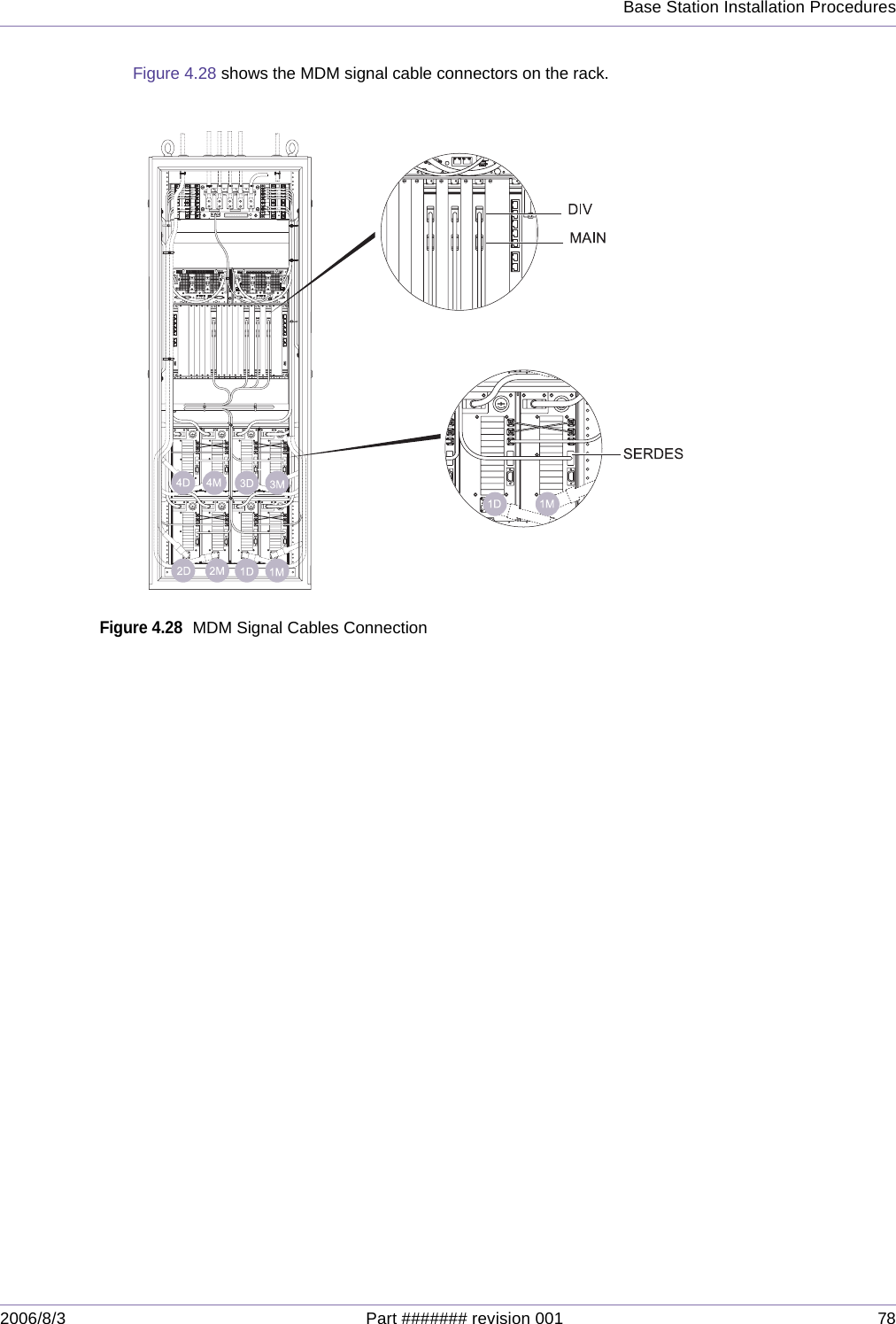
Users Manual Part II

2006/8/3 Part ####### revision 001 39Chapter 4Chapter 4BASE STATION INSTALLATION PROCEDURESThis chapter provides procedures for installing the rack and their internal components. It also provides an overview about installing the antenna used with the NPM2000 base station.Before proceeding with this chapter, you must complete all the tasks described in Chapter 3.ContentsInstalling the Rack ......................................................................................................................................... 40Removing the Rack’s Rear Panel .......................................................................................................... 41Prepare the Installation Location  ........................................................................................................... 44Position the Rack ................................................................................................................................... 46Secure the Rack  .................................................................................................................................... 48Attaching Ground and Power Cables ............................................................................................................ 51Ground the Rack .................................................................................................................................... 52Attach the Main and Return Power Cables ............................................................................................ 54Attaching the Shelves and Modules .............................................................................................................. 58Rack Layout ........................................................................................................................................... 59Attach the Digital Shelf to the Rack  ....................................................................................................... 60Attach the Radio Module to the Rack  .................................................................................................... 62Cover Empty Radio Module Slots .......................................................................................................... 63Populating the Digital Shelf ........................................................................................................................... 64Shelf Layout ........................................................................................................................................... 65Insert CompactPCI Power Supplies  ...................................................................................................... 67Test CompactPCI Power Supplies  ........................................................................................................ 68Insert the Digital Shelf Cards ................................................................................................................. 70Cover Unused Card Slots  ...................................................................................................................... 72Connecting the Cables .................................................................................................................................. 73Connect the PDP Power Cables ............................................................................................................ 74Connect the MDM Signal Cables ........................................................................................................... 77Connect the Ethernet Cables (where applicable)  .................................................................................. 79Connect the PDP Monitor Cable ............................................................................................................ 80Connect the LO Crossover Cables  ........................................................................................................ 81
Base Station Installation Procedures2006/8/3 Part ####### revision 001 40INSTALLING THE RACKThese procedures describe how to prepare the floor for rack installation, move the rack into place, and secure the rack to the floor, and to the ceiling.Table 4.1 shows the actions described in this section.NOTE:When you install the rack, finish positioning and leveling the rack. This makes leveling the rack easier and minimizes the potential for errors that may occur during rack placement. The rack is suitable for mounting on concrete or other non-com-bustible surfaces only.Figure 4.1 shows the factory default status of the NPM2000.Figure 4.1NPM2000 Factory default statusAction PageRemoving the Rack’s Rear Panel 41Prepare the Installation Location 44Position the Rack 46Secure the Rack 48Table 4.1Installing the Rack Procedure Summary
41 Part ####### revision 001 2006/8/3Macro Base Station Installation Procedures (NPM2000)Removing the Rack’s Rear PanelThe rear panel of the rack is removable. Removing the rear panel may improve the efficiency of the installation work in some cases.Figure 4.2 shows the rear panel to be removed.To remove the rear panel, raise each lever by pressing the push button as shown in the Figure 4.2. Before fully removing the rear panel, first disconnect the frame ground cable attached to the back of the panel.To attach the panel, place the panel in position and then press each lever to the down posi-tion. Also, you can lock/unlock the lever by clicking the small slide lock on it. Figure 4.2Removable Rear Panel of the Rack Lever Slide LockPush ButtonSlide Lock
Base Station Installation Procedures2006/8/3 Part ####### revision 001 42Figure 4.3 shows how to remove the frame ground attached to the rack’s filler panel.Figure 4.3Removing the Frame Ground
43 Part ####### revision 001 2006/8/3Macro Base Station Installation Procedures (NPM2000)Figure 4.4 shows the status when the rear panel was removed.Figure 4.4Rack Status with Rear Panel Removed
Base Station Installation Procedures2006/8/3 Part ####### revision 001 44Prepare the Installation LocationThis procedure applies to installing the base station on a concrete floor and securing the rack using M12 concrete expansion bolts (called anchor bolts in this document). By factory default, a base kit is bolt-attached to the rack. Remove the base kit before installing the rack with the anchor bolts. Also, please be reminded that the isolation pad – a part of the base kit – is required for the anchor-bolt-installation.  For positiong the rack with the adjusting bolts on the floor, leave the base kit as it is.Figure 4.5 shows the base station rack outline.Figure 4.5NPM2000 Rack OutlineTo prepare the installation location1Mark with a chalk line the location where you will install the rack. If there are overhead requirements, use a plumb line to align the rack vertically.The rack has a footprint of 600 mm by 600 mm. The rack is 1600 mm in height.Install two eyelet bolts in the top of the rack if you intend to use a crane to move the rack.2Verify that there is adequate space for the rack:120=40Px355
45 Part ####### revision 001 2006/8/3Macro Base Station Installation Procedures (NPM2000)Remove the radio module shelf at the bottom by loosening eight M5 screws and pulling the radio module shelf forward. If necessary, also remove the guide angle (L shaped metal bracket) which was used for the removed radio moduel shelf. iMove the rack to the intended installation location.ii Ensure that you have room for the rack, its cabling, and enough space for airflow and the insertion and removal of components. See page 22 for airflow requirements.3Place the rack in the precise location designated for it using the chalk line as your guide.4Draw the anchor hole locations on the concrete floor tracing the anchor hole in the rack. Use the four outer locations and trace the entire shape of the anchor holes. Remove the rack.Figure 4.6 shows the anchor hole locations to be traced.Figure 4.6Anchor Hole Locations5Punch the concrete in the outer edge of each anchor guide using the concrete punch. This will make drill-ing the anchor holes easier.6Drill an anchor hole  100 mm (3.9 inch) deep on the outer edge of each anchor hole using a 12.7 mm (0.5 inch) hammer drill.7If the drill bit hits a metal reinforcement bar, move the hole location to the inner edge of the anchor guide and repeat steps 5 and 6.8Ensure that the holes are 100 mm (3.9 inch) deep; otherwise, the anchor bolts will not sit properly.9Clean each anchor hole thoroughly using a vacuum cleaner with a narrow nozzle attachment that can reach into the hole and remove the debris.
Base Station Installation Procedures2006/8/3 Part ####### revision 001 46Position the RackThis procedure describes how to position and level the rack.To position the rack1Place the isolation pads at the four corners to fit on the drilled anchor holes.Figure 4.7 shows how to place the isolation pads.Figure 4.7Position of the Isolation Pads2Place the rack in the precise location designated for the rack using the chalk line and optional drilled holes as your guide. Ensure that the rack is positioned on the isolation pads.Figure 4.8 shows the correct position of the rack.Isoation Pad
47 Part ####### revision 001 2006/8/3Macro Base Station Installation Procedures (NPM2000)Figure 4.8The Rack Position3Ensure that the rack is vertically aligned and front-to-rear using a torpedo level. Add shims as needed until the rack is level.
Base Station Installation Procedures2006/8/3 Part ####### revision 001 48Secure the RackThis procedure describes how to secure the rack in place. The rack may be secured to the ground and to the ceiling.Figure 4.9 shows the location of the junction bar and the support bolt holes.Figure 4.9Support Bolt Hole LocationsTo secure the rack1Ensure that the rack is correctly positioned and vertically aligned.NOTE:To secure the upper part of the rack, remove the elelet bolts bofore securing the rack. Figure 4.10 shows how to handle the anchor bolts.Figure 4.10Anchor BoltsAnchor + Isolation PadAnchor BoltWasherBush (Isolation)Rack (bottom)Isolation Pad (t5mm)Anchor HoleIsolation Pad PositionIsolation Pad (t5mm)Anchor HoleFront70 7062.545860079.5600460
49 Part ####### revision 001 2006/8/3Macro Base Station Installation Procedures (NPM2000)2Secure the rack to the floor. If you are using anchor bolts, complete the following steps:iAttach the nuts to the anchor bolts in the manner that the screw part comes first.ii Ensure that the anchor hole, the rack fixing hole, and the isolation pad fixing hole are properly aligned.iii Set the isolation bushing to the fixing hole of the rack.iv Set the flat washer on the isolation bushing.vInsert the anchor bolt into the anchor hole through the flat washer, the isolation bushing, and the rack. vi Drive the shaft into until it reaches to the top of the anchor bolt.vii Tighten the nut using a tool.  The torgue value is 42 N•m (371.3 inch-pounds).viii Reattach the radio module shelf using the M5 screws. Torque the screws to 3.0 N•m (26.6 inch-pounds).Position the rack on the floor without anchorsIn the case of positiong the rack on the floor without anchors, follow the procedures below.1Remove the radio module shelf at the bottom of the rack by loosening eight M5 screws and pulling the radio module shelf forward. If necessary, also remove the guide angle (L shaped bracket) which was used for the removed radio moduel shelf. 2Raising the rack or lying the rack on its side for the stability, attach the ajusting bolts on the bottom of the base.Figure 4.11 shows how to push the adjusting bolts.Figure 4.11Adjusting BoltsFloor Standing+Adjust Boltmin 70mm50 5Adjust NutSet NutAdjust BoltRack (bottom)Isolation pad (t5mm)BaseAdjust BoltAAdjust Bolt Holes (M16)(50) 500600View A5046.5 46.5460553
Base Station Installation Procedures2006/8/3 Part ####### revision 001 50NOTE:Ensure that the screw part of the adjusting bolt is pushed 15 mm deep into the base. Fix the adjusting bolts so that the loading is evenly supported by four adjust-ing bolts. Do not use the adjusting bolts under the the following locations: - Where a waterdrop is likely to spread out (i.e. outdoor location)- Where high tempereature, high humidity, or corrodible gas is likely to occur.- Where much dust or oil mist is likely to occur. 3Position the rack on the given location.4Fix the adjusting bolts with the nuts so that the rack is leveled. Then, secure the adjusting bolts with the fixing nuts.!WARNING:Ensure that the gross weight of the rack does not overload on eitheradjusting bolt while the rack being raised or being put on the floor.  Otherwise, the rackmight be damaged.!WARNING:For the safety reason, it is recommended to secure the rack usingthe anchor bolts.
51 Part ####### revision 001 2006/8/3Macro Base Station Installation Procedures (NPM2000)ATTACHING GROUND AND POWER CABLESThese procedures describe how to ground and power the base station. Table 4.2 shows the actions described in this section.Action PageGround the Rack 52Attach the Main and Return Power Cables 54Table 4.2Attaching Ground and Power Cables Procedure SummaryWARNING:Ensure that all of the circuit breakers on power distribution panel(PDP) are in the OFF (down) position before attaching any cables. Failure to do somay result in personal injury and cause damage to or destruction of the base station.
Base Station Installation Procedures2006/8/3 Part ####### revision 001 52Ground the RackThe rack requires a ground cable connecting the rack to the building’s grounding system. Figure 4.12 shows the cables used to ground the rack.Figure 4.12Ground CablesTo ground the rack1Ensure that all the circuit breakers on the PDP are in the OFF (down) position.2Connect the main ground cable to the building’s grounding system using a minimum of #6 AWG stranded copper wire.3Terminate the main ground cable with a two-hole compression lug. Apply an anti-oxidant solution to the cable before attaching the compression lug.NOTE:When crimping the compression lug, ensure that you are using the appropri-ate tool. Compression lugs for #6 AWG wire are colored blue and require that a blue die be used with the crimping tool.GNDGNDRTNRTN-48V-48V-48 FEED-B RTN-48 FEED-B RTN-48 FEED-A RTN-48 FEED-A RTNGNDGNDGNDGNDRTNRTN-48V-48VRMRM1M1M1D1DRMRM3M3MRMRMRMRM3D3DRMRM5M5MARTRTCPUCPUA2A2CPUCPUA1A15D5DRMRMRMRM6D6DB1B1CPUCPUB2B2CPUCPURTRTB6M6MRMRM4D4DRMRMRMRM4M4MRMRM2D2D2M2MRMRMA-A Cross SectionB-B Cross SectionTo Rack GroundTo PDP GroundRack Ground B Rack Ground A
53 Part ####### revision 001 2006/8/3Macro Base Station Installation Procedures (NPM2000)Figure 4.13 shows the dimension of the compression lug.Figure 4.13Compression Lug Dimensions4Apply an anti-oxidant solution to the ground terminals on the rack.5Connect the compression lug on the main ground cable to one of the two ground terminals, as shown in Figure 4.14. Use a hex nut with a split-lock washer when securing the cable. Torque each hex nut to 0.90 N•m (8.0 inch-pounds).Figure 4.14Ground Terminals on the PDPAttach the compression lug using two hex screws with locking and external tooth washers.6Dress and label the ground cables according to the standards and requirements of your site.WLHole SpacingL : 2.52”W: 0.6”Hole Spacing: 0.75”Stud Hole Size: 1/4
Base Station Installation Procedures2006/8/3 Part ####### revision 001 54Attach the Main and Return Power CablesBefore proceeding with this procedure, ensure that all the necessary site cable layout, runaway, and grid work has been completed.To attach the main and return power cables1Ensure that all the circuit breakers on the PDP are in the OFF (down) position.2Ensure that the main –48V DC power supply is powered off.3FEED-AiConnect the main power cable FEED-A to the negative terminal on your –48V DC power supply using a minimum of #2 AWG stranded copper wire.ii Connect the return power cable FEED-A to the positive terminal on your –48V DC power supply using a minimum of #2 AWG stranded copper wire.4FEED-BiConnect the main power cable FEED-B to the negative terminal on your –48V DC power supply using a minimum of #2 AWG stranded copper wire.ii Connect the return power cable FEED-B to the positive terminal on your –48V DC power supply using a minimum of #2 AWG stranded copper wire.5Terminate each of the cables with a two-hole compression lug with the dimensions shown in Figure 4.13 on page 53. Apply an anti-oxidant solution to each cable before attaching the compression lug.NOTE:When crimping the compression lug, ensure that you are using the appropri-ate tool. Compression lugs for #2 AWG wire are colored brown and require that a brown die be used with the crimping tool.6Apply an anti-oxidant solution to the main and return terminals on the PDP.7Connect the compression lugs on the return power cables to each return terminal shown in Figure 4.15. Use hex nuts with split-lock washers when securing the cables. Torque each hex nut TBD N•m (inch -pounds).8Connect the compression lugs on the main power cables to each –48V DC power terminal shown in Figure 4.15. Use hex nuts with split-lock washers when securing the cables. Torque each hex nut to TBD N•m (inch-pounds).WARNING:Ensure that the necessary requirements and procedures have beenreviewed prior to the start of any power-related activity. Ensure that the –48V DCpower supply and the base station are powered off before you begin this procedure.Failure to turn off the power supply may result in personal injury or death and causedamage to or destruction of the base station and surrounding equipment.
55 Part ####### revision 001 2006/8/3Macro Base Station Installation Procedures (NPM2000)Table 4.3 shows the preferable cable thickness proportional to its loop length.Figure 4.15Main and Return Power Terminals1Ensure the main and return power cables are connected to the main power supply correctly by perform-ing a continuity test on each cable.2Dress and label the main and return power cables according to the standards and requirements of your site.NOTE:Ensure that the main and return power cables are tied in a manner that mini-mizes the potential for creating electromagnetic fields. When tied together, the main and return power cables should be arranged in an alternating order.To test the power supply voltage and ground1Ensure that all circuit breakers (CB) are in the OFF (down) position.2Remove the fuse F1 and F2 from the PDP by holding down and turning it counterclockwise.3Configure your multimeter to read DC voltage. Autoscaling may be used.Loop Length f65 130 195 260Sector m19.8 39.6 59.4 79.21 #7 #4#2#12#4#21/02/03 #3 1/0 3/0 4/04#22/04/0–Table 4.3Cable Thickness
Base Station Installation Procedures2006/8/3 Part ####### revision 001 564If the base station has a pre-installed digital shelf, disconnect the power cable from the power connector which is connected to FlexAlarm A and B on the digital shelf. Leave the power cables connected to termi-nals "CPCI A1", "CPCI A2", "CPCI B1", "CPCI B2", and "GND" on the PDP. 5Test the voltage potential between the ground and return pins:Figure 4.16 shows the pinout of the power cable connector.Figure 4.16Power cable connector pinoutiConnect the multimeter probes to pins A2 (Ground) and A3 (Return). The probes to be connected to pins A2 and A3 are not specified. Each probe may be connected to either pin.ii Observe the voltage reading on the multimeter. The voltage should be less than ±0.5V from 0.If the voltage is greater than ±0.5V, there may be a grounding problem. See the documentation that ships with your power supply for troubleshooting procedures. Do not power on the base station until the problem has been resolved.6Test the voltage potential between the A1 (–48V) and A3 (Return) pins:iTurn on CBA7 on the PDP.ii Connect the black multimeter probe (–) to pin A3 (Return).iii Connect the red multimeter probe (+) to pin A1 (–48V). iv Observe the voltage reading on the multimeter. The voltage should be between –46V and –56V.If the voltage is not between –46V and –56V, there may be a problem with the main power supply. See the documentation that ships with your power supply for troubleshooting procedures. Do not power on the base station until the problem has been resolved.7Test the voltage potential between the –48V and ground pins:iEnsure that CBA7 on the PDP is turned on.ii Connect the black multimeter probe (–) to pin A2 (Ground).iii Connect the red multimeter probe (+) the pin A1 (–48 V).iv Observe the voltage reading on the multimeter. The voltage should be between –46V and –56V.vIf the voltage is not between –46V and –56V, there may be a problem with the ground or the main power supply. See the documentation that ships with your power supply for troubleshooting proce-dures. Do not power on the base station until the problem has been resolved.8Test the voltage potential between the ground and return pins while the circuit is powered on:iEnsure that CBA7 on the PDP is turned on.ii Connect the black multimeter probe (–) to pin A2 (Ground).iii Connect the red multimeter probe (+) the pin A3 (Return).
57 Part ####### revision 001 2006/8/3Macro Base Station Installation Procedures (NPM2000)iv Observe the voltage reading on the multimeter. The voltage should be less than ±0.5V.If the voltage is greater than ±0.5V, there may be a grounding problem. See the documentation that ships with your power supply for troubleshooting procedures. Do not power on the base station until the problem has been resolved.9 If all the tests described in steps 5-8 passed, then the rack is properly grounded and the main power supply is operating correctly. If any of the tests failed, investigate and correct the problem. Repeat this procedure after corrective action is taken. Do not power on the base station if any of the tests failed.10 Disconnect both probes from the power cable.11 Power off CBA7 on the PDP by setting it to the OFF (down) position.12 Reconnect the power cable to the power connector which is connected to FlexAlarm A and B on the dig-ital shelf.13 Reinstall the fuses F1 & F2 in the PDP by holding down and pressing it clockwise.
Base Station Installation Procedures2006/8/3 Part ####### revision 001 58ATTACHING THE SHELVES AND MODULESThese procedures describe how to attach the shelves and modules to the rack.Table 4.4 shows the actions described in this section.Action PageAttach the Digital Shelf to the Rack 60Attach the Radio Module to the Rack 62Cover Empty Radio Module Slots 63Table 4.4Attaching the Shelves and Modules Procedure Summary
59 Part ####### revision 001 2006/8/3Macro Base Station Installation Procedures (NPM2000)Rack LayoutThe digital shelf slides into its bay and bolt directly to the rack using M5 screws. The recommended torque value for each M5 screw is 3.0 N•m (26.6 inch-pounds).The radio modules slide into their respective slots and bolt to each radio module shelf using thumb screws. The empty slots are covered with filler panels. shows the rack layout.Figure 4.17Rack Layout
Base Station Installation Procedures2006/8/3 Part ####### revision 001 60Attach the Digital Shelf to the RackThe digital shelf is installed in the middle bay in the rack.To attach the digital shelf to the rack1Remove the digital shelf from its protective bag.NOTE:The shelf weighs approximately 35 kg before it is filled with cards.2Slide the digital shelf into the middle bay in the rack. If the bay is too tight to accommodate the digital shelf, loosen the M5 screws that hold the units to be located on above/below the accommodation area. This should provide enough space for you to slide in the digital shelf. If any of the cable brackets interfere with the insertion of the digital shelf, remove them. The cable brackets attach to the rack using M5 screws.Figure 4.18 shows the digital shelf and its mounting space in the rack.Figure 4.18Digital Shelf MountingWARNING:Your base station may arrive with the digital shelf already populatedwith cards. If this is the case, ensure that you are properly grounded before handlingthe shelves. Failure to do so may damage the cards.1235791011121315161718192021
61 Part ####### revision 001 2006/8/3Macro Base Station Installation Procedures (NPM2000)3Attach the digital shelf to the rack using ten M5 screws. Torque each screw to 3.0 N•m (26.6 inch-pounds).Figure 4.19Mount Screws4Connect two frame ground cables to the rack and reattach any cable brackets you removed.5Retighten any M5 screws that hold the units to be located on above/below the accommodation area.
Base Station Installation Procedures2006/8/3 Part ####### revision 001 62Attach the Radio Module to the RackSome slots for your base station’s radio module may be covered with filler panels.To insert the radio modules in the rack1Remove the radio module from its protective bag.2Orient the radio module properly.3Slide the radio module into the first available radio module slot. The slots should be filled from left to right, then top to bottom.4Ensure that the radio module is anchored into the guide shoe in the back of the radio module shelf.Figure 4.20 shows how to anchor the radio module into the guide in the back of the radio module shelf.Figure 4.20Back of the Radio Module Shelf5Secure the module in the slot using four thumb screws, one in each corner. Torque the thumb screws to 1.5 N•m (13.3 inch-pounds).6Ensure that the radio module is secure by grasping the handle on the front panel and pulling lightly. The radio module should not move. If the radio module does move, ensure that the thumb screws are attached to the shelf assembly and that the module is seated correctly. If necessary, remove the module and repeat this procedure.7Repeat steps 1 to 6 for the remaining radio modules.!CAUTION:Each radio module weighs approximately 11kg.EXT/LNASERDESUARTANTESFUUARTEXT/LNASERDESANTLO OUTLO INPOWER SUPPLY
63 Part ####### revision 001 2006/8/3Macro Base Station Installation Procedures (NPM2000)Cover Empty Radio Module SlotsAny empty slots in the radio module shelves should be covered with radio module filler panels. The radio module filler panels protect the other radio module from dust.To cover unused slots with radio module filler panels1Remove the radio module filler panel from its protective bag.2Orient the filler panel vertically.3Secure the filler panel over the radio module slots using four thumb screws, one on each corner. Torque the screws to 1.5 N•m (13.3 inch-pounds).4Ensure that the filler panel is secure by grasping the thumb screw on the front panel and pulling lightly. The filler panel should not move. If the filler panel does move, ensure that the mounting screws are attached to the radio module shelf assembly. If necessary, remove the filler panel and repeat this proce-dure.
Base Station Installation Procedures2006/8/3 Part ####### revision 001 64POPULATING THE DIGITAL SHELFThese procedures describe how to install the CompactPCI power supplies and cards into the digital shelf. Table 4.5 lists the actions described in this section.NOTE:Your base station may arrive with the shelves already populated. If this is the case, ensure that the cards are properly secured in the shelf and proceed to the next section. Depending on the configuration of your base station, the exact number, layout, model, and faceplates of the cards may vary. Action PageInsert CompactPCI Power Supplies 67Test CompactPCI Power Supplies 68Insert the Digital Shelf Cards 70Cover Unused Card Slots 72Table 4.5Populating the Shelves Procedure SummaryWARNING:Failure to insert a card in the correct slot may result in damage to ordestruction of the card or shelf. Ensure that all the cards are in the correct slots beforepowering on the shelf.
65 Part ####### revision 001 2006/8/3Macro Base Station Installation Procedures (NPM2000)Shelf LayoutDigital Shelf LayoutTable 4.6 and Figure 4.21 show the layout of the front-facing cards on the digital shelf.Figure 4.21Digital Shelf Layout (Front View)Slot Front-Facing Card Slot From-Facing CardUpper (3U) Lower (6U) Upper (3U) Lower (6U)1 FlexManager Ethernet Switch 1 11 Flex Power MC2 (incl. HDD)2123 Flex Power Sector1-SC 13 Flex Power Sector4-SC4 FlexPower Sector1-MDM 14 Flex Power Sector4-MDM5Flex Power Sector2-SC 156 Flex Power Sector2-MDM 167Flex Power Sector3-SC 178 Flex Power Sector3-MDM 189 19-2010 FlexPower MC1 (incl. HDD) 21 FlexManager Ethernet Switch2Table 4.6Digital Shelf Layout (Front-Facing Cards)Ethernet Switch (slots 1, 21)
Base Station Installation Procedures2006/8/3 Part ####### revision 001 66Table 4.7 and Figure 4.22 show the layout of the rear-facing cards on the digital shelf.Figure 4.22Digital Shelf Layout (Rear View)Slot Rear-Facing Card Slot Rear-Facing Card1 Switch RTM 112123134 MDM RTM 14 MDM RTM5156MDM RTM 167178MDM RTM 189 19-2010 21 Switch RTMTable 4.7Digital Shelf Layout (Rear-Facing Cards)
67 Part ####### revision 001 2006/8/3Macro Base Station Installation Procedures (NPM2000)Insert CompactPCI Power SuppliesThere are two FlexAlarm modules and two grounding studs on the rear side of the digital shelf, as shown in Figure 4.22. The FlexAlarm modules are where the power input connectors and circuit breakers are located.The module cards are installed into the digital shelf in a standard way that should be familiar to all ser-vice technicians. The cards can be installed into slots 2 through 20. (Slots 1 and 21 are reserved for the factory-installed network switches.)To insert CompactPCI power supplies1Push the ejector latch handles toward each other (at the same time) while applying forward pressure to secure the module to the system chassis. See Figure 4.23.2Secure the captive screws on each ejector latch handle.Figure 4.233U and 6U ModulesWARNING:The power supplies use components that are sensitive to electro-static discharges (ESD). Make sure you are wearing an approved and regularly testedgrounded wrist strap connected to the grounding point on the PDP. When you handlethe power supplies, hold them by their handles or edges. Do not touch electrical con-nections, pins, or soldered surfaces.
Base Station Installation Procedures2006/8/3 Part ####### revision 001 68Test CompactPCI Power SuppliesThis procedure describes how to test the digital shelf and the power supplies for it to check the electri-cal faults. Testing the power supplies and the shelf before inserting the cards ensures that, in the unlikely event that an electrical fault does occur, no cards will be damaged.To test CompactPCI power supplies1Verify that all four circuit breakers are in the OFF (down) position before turning on the power.2Turn on the CBA7, CBA8, CBB7, and CBB8 on the PDP.The PWR GOOD LED near each power connector should illuminate. This indicates that the power source is providing voltage on that feed. If one of these LEDs is not illuminated, check the cabling and the power source for that feed.Switch all four circuit breakers to the ON position. It is suggested that you switch on both circuit breakers on one FlexAlarm unit, and then switch on both circuit breakers on the other FlexAlarm unit.The FlexCool fan units will begin cooling the chassis and the FlexManager cards will boot automatically.Power Supply Circuit BreakerFlexAlarm A (1-10) PDP, CBA7FlexAlarm A (11-21) PDP, CBA8FlexAlarm B (1-10) PDP, CBB7FlexAlarm B (11-21) PDP, CBB8Table 4.8Digital Shelf Power Supply Circuit Breaker Summary!CAUTION:After powering up the system, check the fan status LEDs to makesure that the ventilating fans are operational.
69 Part ####### revision 001 2006/8/3Macro Base Station Installation Procedures (NPM2000)Figure 4.24 shows a FlexCool Module.Figure 4.24FlexCool Module3Power off all the power supplies in the digital shelf.4Power off your main –48V DC power supply.
Base Station Installation Procedures2006/8/3 Part ####### revision 001 70Insert the Digital Shelf CardsSee Figure 4.21 for the location of each card. If the configuration of your base station does not use a full complement of cards, some slots will be left empty.Figure 4.25 shows how to properly insert a card into a shelf.Figure 4.25Card InsertionTo insert the cards into the digital shelf1Ensure that there are no obstructions in the slot or on the guide rails and check the backplane for bent pins.If there are bent pins, the backplane is damaged and requires repair. Report any damaged equipment to your field support coordinator as soon as possible.2Remove the card from its antistatic bag.3Set the two ejectors handles on the card in the open position by turning the handles away from the center of the front panel.In the open position, the ejector handles are at an approximately 45° angle from the front panel.The cards use components that are sensitive to electrostatic discharges (ESD). Makesure you are wearing an approved and regularly tested grounded wrist strap con-nected to the grounding point on the PDP. When you handle the cards, hold them bytheir handles or edges. Do not touch electrical connections, pins, or soldered sur-faces.The pins on the backplane are easily damaged. When inserting cards (especially thehard disk drives), ensure that the connectors are properly aligned before applying suf-ficient pressure to seat the card. Apply equal
71 Part ####### revision 001 2006/8/3Macro Base Station Installation Procedures (NPM2000)4Ensure that the mounting screws are withdrawn enough to allow for the insertion of the card.Single-slot cards have two mounting screws, one located under each ejector handle.5Orient the card so that the text on the front panel is right-side up. The guide pins should be located to the right of the ejector handles.6Slide the card into the correct slot. Slot locations are shown on Figure 4.21. Use the guide rails to ensure the connectors are aligned.7Apply sufficient pressure to fully mate the card by pressing on both ejector handles with equal force. If present on the card, the guide pins should slide into the round holes located at the top and the bottom of each slot on the right-hand side.8Lock the card in the slot by turning the ejector handles towards the center of the front panel.In the lock position, the ejector handles are at a 90° angle from the front panel.9Secure the card in the slot by installing the 2.5-mm mounting screws. Torque each screw to 0.36 N•m (3.2 inch-pounds).10 Repeat steps 1 to 9 for the remaining cards.
Base Station Installation Procedures2006/8/3 Part ####### revision 001 72Cover Unused Card SlotsAny empty slots in the digital shelf should be covered with filler panels. The filler panels ensure airflow to the other cards and protect the cards from dust and electromagnetic interference.To cover the unused slots with filler panels1Remove the filler panel from its protective bag.2Single-slot filler panels have two mounting screws. Secure the filler panel in the slot by installing the 2.5-mm (0.1 inch) mounting screws. Torque each screw to 0.36 N•m (3.2 inch-pounds).3If the filler panel does move, ensure that the mounting screws are attached to the shelf frame. If neces-sary, remove the panel and repeat this procedure.4Repeat steps 1 to 3 until all the empty slots are covered with filler panels.
73 Part ####### revision 001 2006/8/3Macro Base Station Installation Procedures (NPM2000)CONNECTING THE CABLESThis section describes the cables connecting the different systems in the base station. Table 4.8 shows the actions described in this section.NOTE:The cables are packaged according to their type. Each cable package is labeled with a part number. Use this part number to identify each cable, and refer to the tables provided in this section for its intended origin and termination point. Action PageConnect the PDP Power Cables 74Connect the MDM Signal Cables 77Connect the Ethernet Cables (where applicable) 79Table 4.9Connecting the Cables Procedure Summary
Base Station Installation Procedures2006/8/3 Part ####### revision 001 74Connect the PDP Power CablesThe PDP power cables are attached to the PDP at the factory. The power cables are already tied to the rack.The PDP power cables consist of #10 or #12 AWG wire with compression lugs on each end. The compression lugs are secured to the terminals with 1/8-inch screws.Component NumberingWhen viewed from the back of the base station, the terminals for the PDP circuit breakers are labeled from upper to the lower on the left side of the terminals. That is, "RM 1M" (upper of –48V terminals on the right side), "RM 2M" (upper of –48V terminals on the left side), "RT A" (lowest of  –48V ter-minals on the right side), and "RT B" (lowest of –48V terminals on the left side). When viewed from the back of the base station, the digital shelf has four power supply connectors. Two are in the FlexAlarm Module A and other two are in the FlexAlarm Module B. The power supply connector in the right is described as –48V 1-10 and another one in the left is described as –48V 11-21. Each FlexAlarm Module A and B is mounted on the top of the digital shelf.When viewed from the front of the base station, the radio module in the shelf are numbered from left to right and bottom to top that is, RM1-M, RM1-D, RM2-M, RM2-D, RM3-M, RM3-D, RM4-M, and RM4-D.Figure 4.26 shows the location of the power connectors on the rack. Figure 4.26Rack Connector Layout1235791011121315161718192021
75 Part ####### revision 001 2006/8/3Macro Base Station Installation Procedures (NPM2000)To connect the PDP power cables1Ensure that PDP circuit breaker in the rack is in the OFF (down) position.2Connect each PDP power cable in the rack. The power connectors are all in the back of the rack. Table 4.10 shows the origin and termination point of each cable.Origin Termination Origin TerminationRM 1M (CBA1) Radio Module Shelf, RM 1-MRM 1D (CBB1) Radio Module Shelf, RM 1-DRM 2M (CBA2) Radio Module Shelf, RM 2-MRM 2D (CBB2)  Radio Module Shelf, RM 2-DRM 3M (CBA3) Radio Module Shelf, RM 3-M CPCI A1 (CBA7) Digital Shelf FlexAlarm A 1-10RM 3D (CBB3) Radio Module Shelf, RM 3-D CPCI A2 (CBA8) Digital Shelf FlexAlarm A 11-21RM 4M (CBA4) Radio Module Shelf, RM 4-M CPCI B1 (CBB7) Digital Shelf FlexAlarm B 1-10RM 4D (CBB4) Radio Module Shelf, RM 4-D CPCI B2 (CBB8) Digital Shelf FlexAlarm B 11-21Table 4.10Rack Power Cable Summary
Base Station Installation Procedures2006/8/3 Part ####### revision 001 76Figure 4.27 shows the PDP power connectors on the rack. Figure 4.27PDP Power Cable Connection1235791011121315161718192021
77 Part ####### revision 001 2006/8/3Macro Base Station Installation Procedures (NPM2000)Connect the MDM Signal CablesThe signal cables are LVDS cables with 14-pin MDR (Miniature Delta Ribbon) connectors on each end. The connectors are secured to their receptacles with latches.To keep the power cables and the antenna cables from being interfered, ensure that the MDM signal cable runs through the middle of the rack’s rear side.Component NumberingWhen viewed from the front of the base station, the radio modules in the bottom shelf are numbered from left to right and top to bottom, that is, RM1-M, RM1-D, RM2-M, RM2-D, RM3-M, RM3-D, RM4-M, and RM4-D.The digital shelf contains a MDM RTM card in slot 4.To connect the MDM signal cables1Connect each MDM signal cable. Table 4.11 shows the origin and termination point of each cable.Origin TerminationRadio Module Shelf 1Radio Module 1-MSERDES connectorDigital ShelfMDM RTM card (slot4)MAIN connectorRadio Module Shelf 1Radio module 1-DSERDES connectorDigital ShelfMDM RTM card (slot 4)DIV connectorRadio Module Shelf 1Radio Module 2-MSERDES connectorDigital ShelfMDM RTM card (slot 6)MAIN connectorRadio Module Shelf 1Radio Module 2-DSERDES connectorDigital ShelfMDM RTM card (slot 6)DIV connectorRadio Module Shelf 2Radio Module 3-MSERDES connectorDigital ShelfMDM RTM card (slot 8)MAIN connectorRadio Module Shelf 2Radio Module 3-DSERDES connectorDigital ShelfMDM RTM card (slot 8)DIV connectorRadio Module Shelf 2Radio Module 4-MSERDES connectorDigital ShelfMDM RTM card (slot 14)MAIN connectorRadio Module Shelf 2Radio Module 4-DSERDES connectorDigital ShelfMDM RTM card (slot 14)DIV connectorTable 4.11Radio Module - MDM Signal Cable Summary
Base Station Installation Procedures2006/8/3 Part ####### revision 001 78Figure 4.28 shows the MDM signal cable connectors on the rack. Figure 4.28MDM Signal Cables Connection1235791011121315161718192021
79 Part ####### revision 001 2006/8/3Macro Base Station Installation Procedures (NPM2000)Connect the Ethernet Cables (where applicable)The Ethernet cables are CAT5 cables with RJ-45 connectors on each end. The cable is the straight-through cable, and each Ethernet switch is connected to each edge router with the straight-through cables. Connect each edge router to two among "22", "23", and "24", all of which are mounted on the digital shelf.  Table 4.12 shows the Ethernet cabling for the base station.Figure 4.29 shows the Ethernet cable connectors on the rack.Figure 4.29Ethernet Cables ConnectionTo connect the Ethernet cables1Connect the Ethernet cables to the Ethernet switches. Table 4.12 shows the origin and termination point of each cable.Connect the Edge router 0 to any among "22", "23", and "24" for both slot 1 and slot 21 of the Switch RTM. Origin TerminationEdge Router 0 Switch RTM (Slot 1) one of "22", "23", “24"Edge Router 0 Switch RTM (Slot 21) one of "22", “23", "24"Edge Router 1 Switch RTM (Slot 1) one of "22", "23", "24"Edge Router 1 Switch RTM (Slot 21) one of "22", "23, "24"Table 4.12Ethernet Cable Summary    Edge Router 1: Redundant Router12357910111213151617181920211235791011121315161718192021
Base Station Installation Procedures2006/8/3 Part ####### revision 001 80Connect the PDP Monitor CableThe PDP monitor cable is shielded twisted pair cable with 9-pin Micro D subminiature connector and 9-pin standard D subminiature connector. The connectors are secured to their receptacles with screws.To keep the power cables and the antenna cables from being interfered, ensure that the PDP monitor cable runs through the middle of the rack’s rear side.Connect the Micro D9 connector to the Digital Shelf and the standard D9 connector to the PDP Alarm Board. Table 4.13   shows the PDP monitor cabling for the base station.Figure 4.30 shows the PDP monitor cable connectors on the rack.Figure 4.30PDP Monitor Cable ConnectionTo connect the PDP monitor cable1Connect the PDP monitor cable between the PDP and the Digital Shelf.Table 4.13 shows the origin and termination point of each cable.Origin TerminationPDP Alarm Board PDP Monitor Digital Shelf FlexAlarm A - ALARM PANEL 2Table 4.13PDP Monitor Cable Summary1235791011121315161718192021
81 Part ####### revision 001 2006/8/3Macro Base Station Installation Procedures (NPM2000)Connect the LO Crossover CablesThe LO crossover cable is coaxial cable with SMA connectors. The connectors are secured to their receptacles with screw coupler.This cable is connected between RM-1M and RM-1D, RM-2M and RM2-D, RM-3M and RM-3D, RM-4M and RM-4D.Table 4.14 shows the LO crossover cabling for the base station.Figure 4.31 shows the LO connectors on the rack.Figure 4.31LO Cable ConnectionTo connect the Lo cables1Connect the LO crossover cables between the PDP and the Digital Shelf.Table 4.14 shows the origin and termination point of each cable.Origin Termination Origin TerminationRM-1M LO IN RM-ID LO OUT RM-3M LO IN RM-3D LO OUTRM-1M LO OUT RM-1D LO IN RM-3M LO OUT RM-3D LO INRM-2M LO IN RM-2D LO OUT RM-4M LO IN RM-4D LO OUTRM-2M LO OUT RM-2D LO IN RM-4M LO OUT RM-4D LO INTable 4.14Lo Cable Summary1235791011121315161718192021
Base Station Installation Procedures2006/8/3 Part ####### revision 001 82

Navigation menu