Sanyo Electric Co NPM-2000-C310 NPM-2000 Wireless Base Station User Manual NPM2 Installation Procedures 1600 mmds NPM2
Sanyo Electric Co Ltd NPM-2000 Wireless Base Station NPM2 Installation Procedures 1600 mmds NPM2
Contents
- 1. Users Manual Part I
- 2. Users Manual Part II
- 3. Users Manul Part III
Users Manul Part III

2006/8/3 Part ####### revision 001 83
Chapter 5
Chapter 5
A
NTENNA
I
NSTALLATION
P
ROCEDURES
This chapter provides an overview of the installation process. Please familiarize yourself with the instal-
lation process in general before proceeding to the next chapter.
Contents
Install the Main and Diversity Antennas ........................................................................................................ 84
Measuring VSWR and Return Loss .............................................................................................................. 88
Measuring the Distance to a Fault ................................................................................................................ 90

Antenna Installation Procedures
2006/8/3 Part ####### revision 001 84
I
NSTALL
THE
M
AIN
AND
D
IVERSITY
A
NTENNAS
These procedures describe the general process for installing the main and diversity antennas. Consult
your field enginnering package for any site-specific antenna installation requirements.
Before You Begin
Before you install the antennas:
Select an installation location away from any objects that might obstruct the RF signals.
Although the base station has non-line-of-site RF capability, obstructions may reduce the
strength of the transmission or reception signals.
Ensure that the type and length of cabling used to connect the main and diversity antennas to
the radio module meet your attenuation and shielding requirements.
Cabling and Connectors
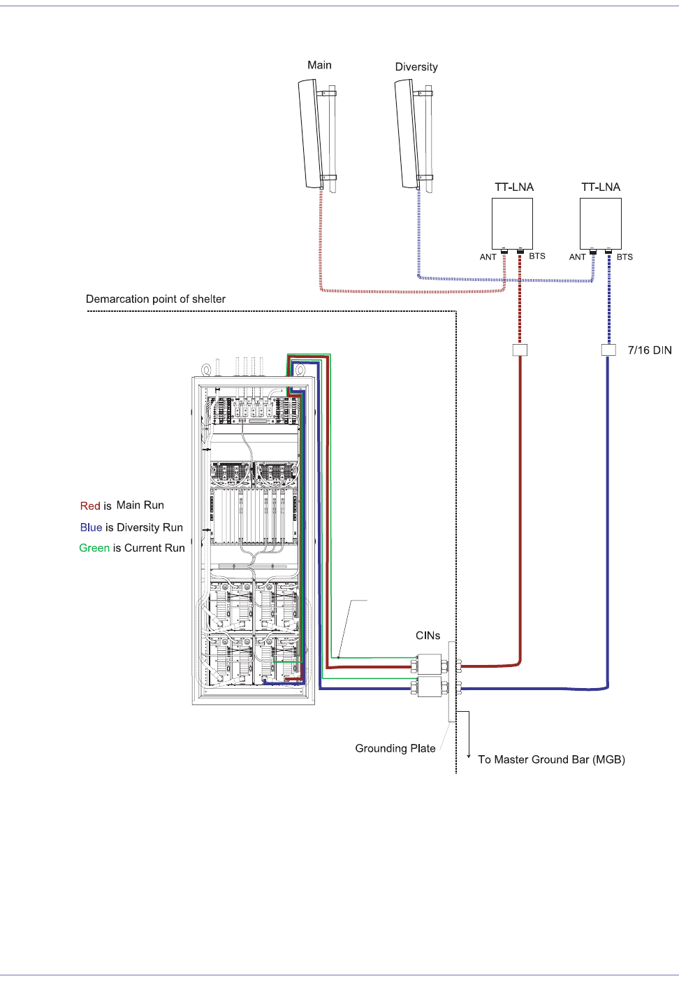
Figure 5.1 shows the main and diversity antenna cabling and connectors.
WARNING:Before proceeding with the installation of the antennas, consult the
applicable local code of wiring for requirements, including: clearance from power and
lightning conductors, proper mounting methods, and antenna grounding.
85 Part ####### revision 001 2006/8/3
Macro Base Station Installation Procedures (NPM2000)
Figure 5.1
Radio Module with TT-LNA Antenna Configuration
To install the main and diversity antennas
1Verify that you have the right type of antennas, both in terms of frequency and direction.
2Run the antenna cable from the rack to the intended location of each antenna.
1235791011121315161718192021
TT-LNA Power Cable
Antenna Installation Procedures
2006/8/3 Part ####### revision 001 86
NOTE:Ensure that the cable remains clear of any sources of potential interference,
such as transmitting equipment or power lines.
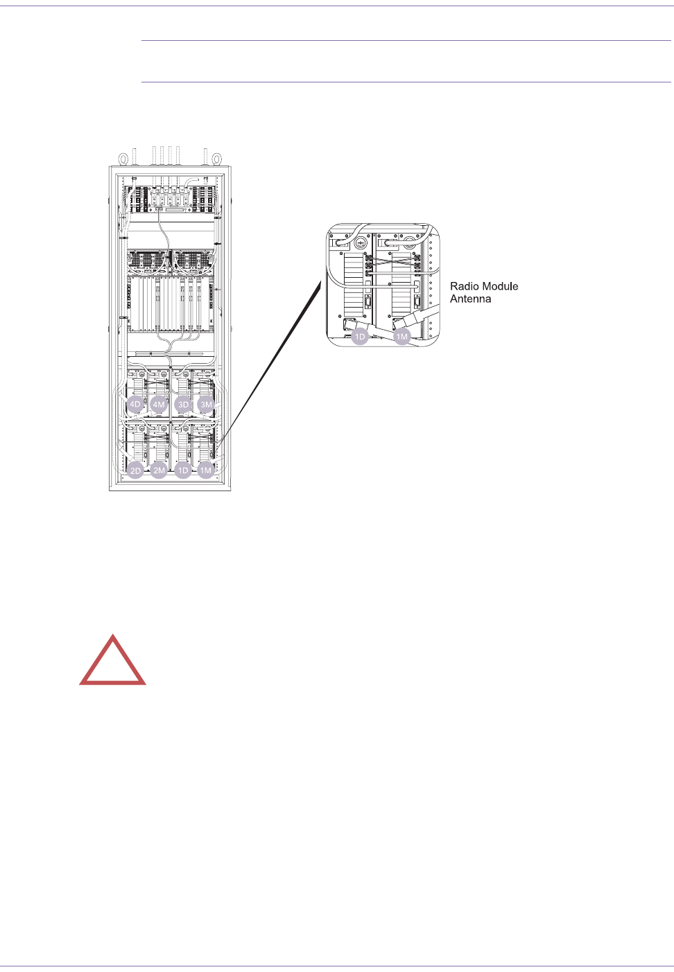
Figure 5.2 shows the radio module antenna connectors on the rack.
Figure 5.2
Radio Module Antenna Connections
3Attach each antenna to your tower or building using the required mounting hardware.
4Orient each antenna to the correct azimuth (direction) and tilt.
5Tighten and secure each antenna.
6Connect the antenna to the radio module:
iInstall each TT-LNA within 3 m (10 feet) of its antenna. The TT-LNAs should be installed as close to
the antennas as possible in order to ensure optimal base station performance. Consult the docu-
mentation that ships with the TT-LNAs for the correct mounting procedures.
!CAUTION:Failure to orient the antennas may seriously affect the performance
of your wireless network.
1235791011121315161718192021

87 Part ####### revision 001 2006/8/3
Macro Base Station Installation Procedures (NPM2000)
ii Connect the Antenna (ANT) port on each TT-LNA to its antenna using a suitable coaxial cable.
Torque each 7/16 DIN connector to 28.0 N•m (247.8 inch-pounds) and ensure each connector is
properly weatherproofed.
iii Install each CIN (also called a bias tee) inside or outside the base station building. Connect the ANT
port on each CIN to the Base Transfer Station (BTS) port on each TT-LNA. Torque each 7/16 DIN
connector to 28.0 N•m (247.8 inch-pounds) and ensure each connector is properly weatherproofed.
NOTE:Ensure that each CIN is installed within 10 m (32 feet) from the base station.
iv Connect the BTS on each CIN to the ANT port on each radio module. The ANT port is located on the
rear side of the radio module.
vConnect the DC port on each CIN to the EXT/LNA port on each radio module. The EXT/LNA port is
located on the rear side of the radio module.
!CAUTION:Do not over-tighten connectors. Overtightening the connectors may
damage the cable and degrade the RF signal.
!CAUTION:Do not over-tighten connectors. Overtightening the connectors may
damage the cable and degrade the RF signal.

Antenna Installation Procedures
2006/8/3 Part ####### revision 001 88
M
EASURING
VSWR
AND
R
ETURN
L
OSS
Voltage standing wave ratio (VSWR) is a ratio of the maximum to minimum voltage as measured
along the length of a mismatched RF transmission line. VSWR indicates the level of impedance
matching between RF equipment (such as amplifiers, cabling, and antennas).
When the impedances of the RF equipment are mismatched, some of the RF energy is reflected back
along the transmission line.
Reflected energy causes inefficiencies in the transmission power output. A VSWR of 1:1, as measured
from antenna cable to the antenna, indicates that 100% of the power output is being radiated by the
antenna.
During a cable sweep, RF equipment should show a VSWR of 1.5:1 or less, as measured from 2500-
2686 MHz. A VSWR greater than 1.5:1 indicates potential problems with the RF equipment.
A high VSWR may be caused by one or more of the following conditions:
Moisture in the external cables or connectors
Faulty equipment
Poor connections between components
Damaged cables or connectors
An open- or short-circuit in RF equipment or cables
Return Loss
Return loss is closely related to VSWR. Return loss is a measure in decibels (dB) of the ratio of forward
to reflected power. For example, if a load has a return loss of 10 dB, then 1/10 of the forward power is
reflected. The higher the return loss, the less energy is being reflected.
Table 5.1 shows the correlation between VSWR, return loss, and the percentage of reflected power.
To measure the VSWR of RF equipment
1Power on and calibrate your cable sweep analyzer.
2Power off the radio module connected to the RF equipment you want to test. See page 93 for a list of cir-
cuit breakers.
VSWR Return Loss (dB) Power Being Reflected (%)
1:1 N/A (infinite value) 0
1.25:1 19.1 1.2
1.5:1 14 4.0
1.75:1 11.3 7.4
2:1 9.5 11.1
5:1 3.5 44.7
N/A (infinite value) 0 100.0
Table 5.1
VSWR, Return Loss, and Reflected Power Conversions

89 Part ####### revision 001 2006/8/3
Macro Base Station Installation Procedures (NPM2000)
3Carefully disconnect the RF equipment and cables you want to test.
4Connect the cable sweep analyzer to the equipment and cables you want to test.
NOTE:Be careful not to damage any cables or connectors when connecting the
analyzer to the RF equipment. Due to the use of the tower-top low noise amplifier (TT-
LNA), all cable sweeps must measure the total length of the cable run (including all
connectors, jumpers, and CIN), using a DIN adapter (female-female) in place of the TT-
LNA.
5Perform the cable sweeps.
See the documentation that comes with your analyzer for information about performing the cable sweep
and interpreting the results.
6Record the results from the cable sweeps. Keeping records of periodic cable sweeps makes trouble-
shooting future problems easier.
7Carefully disconnect the analyzer from the RF equipment.
8Reconnect the RF equipment and cables back to the radio module.
9If any of the connectors are outdoors, ensure that they are resealed according to the procedures of your
site.
10 Reconnect the RF equipment to the radio module.
11 Power on the radio module. See page 93 for a list of circuit breakers.
!WARNING:Extreme care must be taken when connecting or disconnecting the
coaxial antenna cable to avoid damage to the center pins. Connectors should be
torqued to a maximum of 28.0 N•m (247.8 inch-pounds) and be free of dirt or moisture.
Do not over-torque the connectors as this can damage the center pin and cause cable
faults and other RF problems.

Antenna Installation Procedures
2006/8/3 Part ####### revision 001 90
M
EASURING
THE
D
ISTANCE
TO
A
F
AULT
Distance to fault (DTF) is a measurement of VSWR or return loss based on distance. A DTF test indi-
cates the distance to a short, open, or load. Perform a DTF test whenever a VSWR test reveals that the
antenna system is not operating within specifications.
To accurately interpret the results from a DTF cable sweep, you need to know the lengths of your
cables and the location of any devices or connectors attached to those cables. Comparing the results of
the test with the layout of your antenna system will help you to determine if problems are caused by
faulty devices, connectors, or cables.
To measure the distance to fault
1Power on and calibrate your cable sweep analyzer.
2Power off the radio module connected to the RF equipment you want to test. See page 93 for a list of cir-
cuit breakers.
3Carefully disconnect the RF equipment and cables you want to test.
4Connect the cable sweep analyzer to the equipment and cables you want to test.
NOTE:Be careful not to damage any cables or connectors when connecting the
analyzer to the RF equipment.
5Perform the cable sweeps.
See the documentation that comes with your analyzer for information about performing the cable sweep
and interpreting the results.
6Document the results from the cable sweeps.
Keeping records of periodic cable sweeps will make troubleshooting future problems easier.
7Carefully disconnect the analyzer from the RF equipment.
8Reconnect the RF equipment and cables back to the radio module.
If any of the connectors are outdoors, ensure that they are resealed according to the procedures of your
site.
9Power on the radio module. See page 93 for a list of circuit breakers.

2006/8/3 Part ####### revision 001 91
Chapter 6
Chapter 6
O
N
-S
ITE
C
ONFIGURATION
P
ROCEDURES
This chapter describes how to power on the base station and configure the cards.
Contents
Power On the Base Station ........................................................................................................................... 92
On-Site Configuration Procedures
2006/8/3 Part ####### revision 001 92
Power On the Base Station
The power for the NPM2000 base station is controlled by circuit breakers in the PDP, located at the
top of the rack. digital shelf has its own circuit breaker, whereas radio module has its own fuse.
To power on the base station
1Ensure that your main –48V DC power supply is powered on and is providing a power source that meets
the electrical requirements listed on page 23.
2Ensure that Power-A LED and Power-B LED on the front panel of PDP are lighted.
3Set all except those for non-installed radio modules and routers to the ON (up) position on the PDP.
4Power on the power supply in the digital shelf.
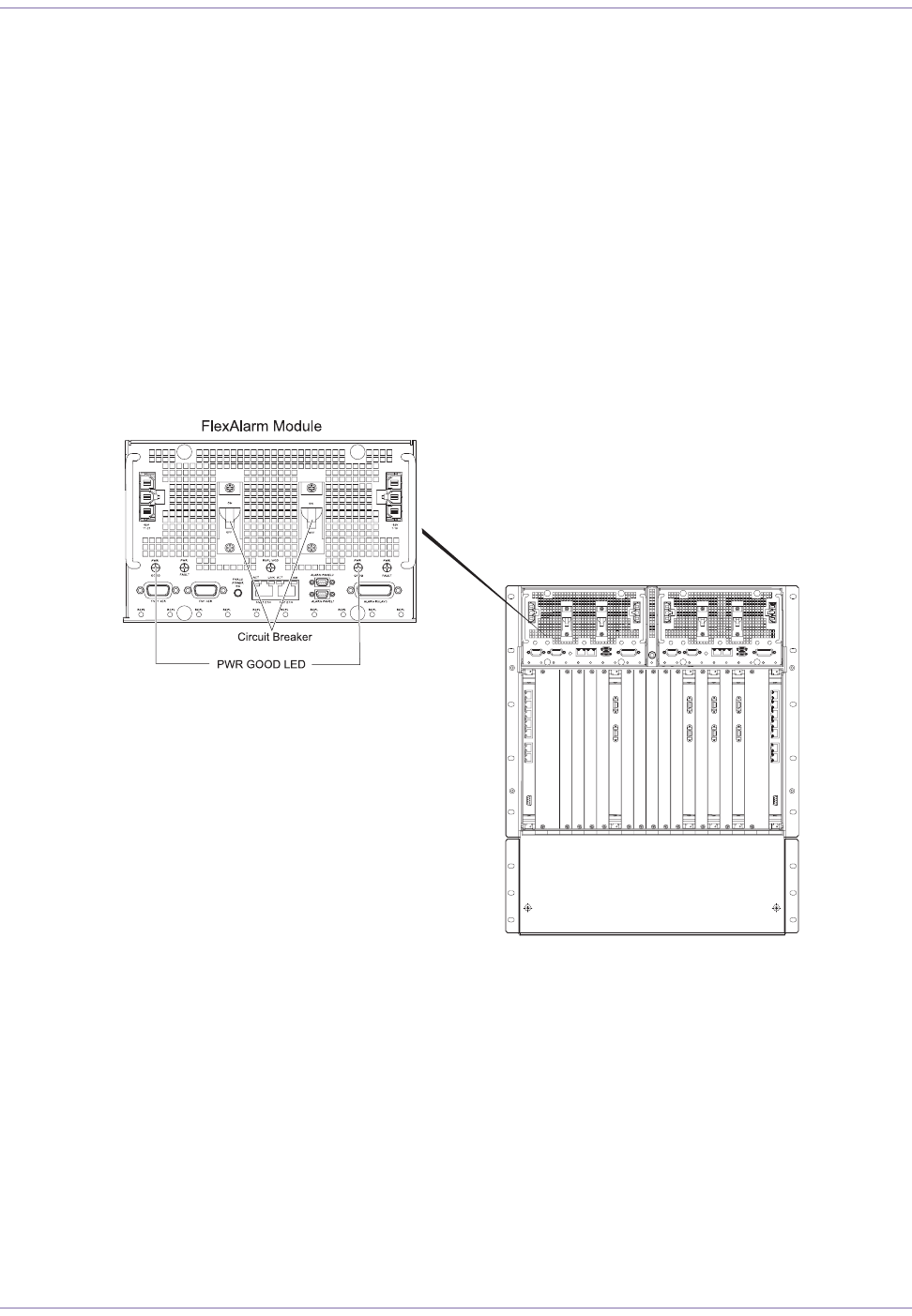
Figure 6.1 shows the circuit breakers on the digital shelf.
Figure 6.1
Circuit Breakers on the Digital Shelf
iThe PWR GOOD LED near each power connector should illuminates. This indicates that the power
source is providing voltage on that feed. If one of these LEDs is not illuminated, check the cabling
and the power source for that feed.
ii Switch all four circuit breakers to the ON position. It is suggested that you switch on both circuit
breakers on one FlexAlarm unit, and then switch on both circuit breakers on the other FlexAlarm
unit.
93 Part ####### revision 001 2006/8/3
Macro Base Station Installation Procedures (NPM2000)
The FlexCool fan units will begin cooling the chassis and the FlexManager cards will boot automatically.
Table 6.1 shows the circuit breakers for each power supply.
5Power on each radio module separately. Table 6.1 shows the circuit breakers for the radio module.
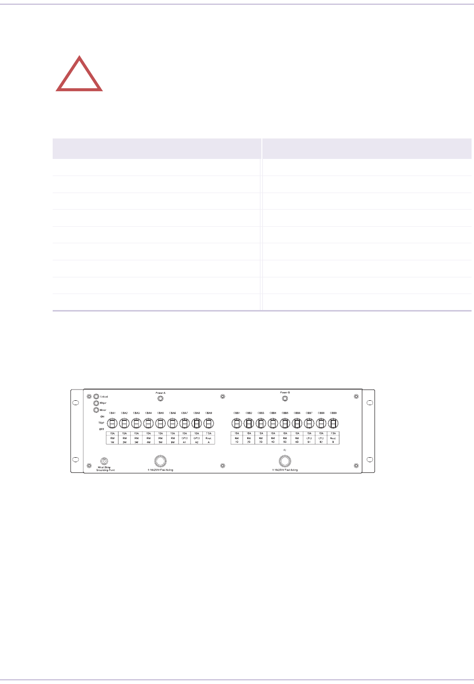
Figure 6.2 shows the circuit breakers on the PDP front panel.
Figure 6.2
Circuit Breakers on the PDP Front Panel
!CAUTION:After powering up the system, check the fan
status LEDs to make sure that the ventilating fans are opera-
tional.
Origin Termination Origin Termination
RM 1M (CBA1) Radio Module Shelf, RM 1-M
RM 1D (CBB1) Radio Module Shelf, RM 1-D
RM 2M (CBA2) Radio Module Shelf, RM 2-M
RM 2D (CBB2) Radio Module Shelf, RM 2-D CPCI A1 (CBA7) Digital Shelf FlexAlarm A 1-10
RM 3M (CBA3) Radio Module Shelf, RM 3-M CPCI A2 (CBA8) Digital Shelf FlexAlarm A 11-21
RM 3D (CBB3) Radio Module Shelf, RM 3-D CPCI B1 (CBB7) Digital Shelf FlexAlarm B 1-10
RM 4M (CBA4) Radio Module Shelf, RM 4-M CPCI B2 (CBB8) Digital Shelf FlexAlarm B 11-21
RM 4D (CBB4) Radio Module Shelf, RM 4-D RT A Option
RT B Option
Table 6.1
Circuit Breakers
F1

On-Site Configuration Procedures
2006/8/3 Part ####### revision 001 94

95 Part ####### revision 001 2006/8/3
Macro Base Station Installation Procedures (NPM2000)
Appendix A
Appendix A
D
ECOMMISSIONING
P
ROCEDURES
This appendi describes how to safely take an base station out of service.
Contents
Decommission a Base Station ............................................................................................................................

On-Site Configuration Procedures
2006/8/3 Part ####### revision 001 96
Decommission a Base Station
Decommissioning occurs whenever a base station is taken out of service or moved to a new location.
To decommission a base station
1Shutdown the sector controllers:
iEstablish an SSH session with each card, as described in the System Administration Reference.
ii Shutdown each card by typing:
shutdown now
↵
2Shutdown the digital shelf by setting all slots to off.
iSet all slots to off by typing the following command on the active FlexManager:
off
3Power off the base station by setting all breakers except those for non-installed radio modules and rout-
ers to the OFF (down) position.
4Power off the main power supply for the base station. With most power bays, circuit breakers control the
–48V DC feeds to the rack. Ensure that the main power is removed for the rack.
See the documentation that accompanies your main power supply for specific instructions on powering
off the –48V DC feeds to the base station.
After the main power supply is powered off, it is safe to prepare the rack for shipment or storage.
5Package the rack according to the procedures specific to your site. If you remove the cards from the dig-
ital shelf, ensure that the cards are stored in antistatic packaging and that the required documentation is
included.
WARNING:Ensure that the necessary requirements and procedures have been
reviewed prior to the start of any power-related activity. Refer to your cut-over MOP for
procedures specific to your site.

97 Part ####### revision 001 2006/8/3
Macro Base Station Installation Procedures (NPM2000)

On-Site Configuration Procedures
2006/8/3 Part ####### revision 001 98
Appendix B
Appendix B
A
DDING
A
DDITIONAL
S
ECTORS
This appendix describes how to add additional sectors to an base station to increase capacity.
Contents
Pre-Upgrade Preparation....................................................................................................................................
Adding Sectors to a Base Station
Performing the Cutover and Power-On
Acceptance Test Plan for Base Station Upgrade

99 Part ####### revision 001 2006/8/3
Macro Base Station Installation Procedures (NPM2000)
Pre-Upgrade Preparation
Before you begin upgrading the base station, ensure that the following preparations are performed.
These preparations are intended to minimize the interruption of service.
Site-Specific Documentation
Before upgrading the base station, ensure that the documentation described in Table B.1 is updated,
reviewed, and verified.
RF Planning
RF planners should develop a preliminary RF plot of the new sector configuration that accounts for
the location of existing and future users. A change in antenna sector layout may affect the RF planning
for the entire network.
After the RF plot is finalized, it shoud be added to the field engineering package.
Install Additional Antennas and Cabling
Install the new antennas and associated cabling. Each new sector requires two antennas (main and
diversity). See “Install the Main and Diversity Antennas" on page for information.
After installing the antennas and cabling, perform a cable sweep on each and ensure results are within
specifications.
HVAC Requirements
Ensure that the heating, ventilation, and air-conditioning (HVAC) system for the site has the capacity
to handle the additional heat produced by the additional sectors. See “Heat Output" on page for infor-
mation.
Main and Backup Power Supplies
Ensure that the power supplies for the site have the capacity to handle the additional sectors. See
"Electrical Requirements" on page for information. Additional rectifier must be installed and tested
prior to upgrading.
Document Description
Field engineering package Provides site-specific configuration about the base station, such as antenna orienta-
tion, cabling requirements, and inventory.
Method of Procedure (MOP) for
adding sectors Describes the sequence and timing of procedures required for the upgrade
Site-specific fall-back plan Describes any events or triggers that require that the technicians return the base
station to its original configuration.
Table B.1
Sector Upgrade Documentation Requirements

On-Site Configuration Procedures
2006/8/3 Part ####### revision 001 100
Backhaul Capacity
Verify that the backhaul connecting the base station to the network core has the capacity to handle the
additional traffic.
Edge and Core Router Capacity
If the backhaul is upgraded, the edge and core routers may require changes to their physical interface
cards (PIC). Any change must be implemented and tested prior to upgrading.

101 Part ####### revision 001 2006/8/3
Macro Base Station Installation Procedures (NPM2000)
Adding Sectors to a Base Station
This procedure describes how to add additional sectors to a base station. See your updated field engi-
neering package for site-specific information about the upgrade.
To add sectors to a base station
1Install any additional radio modules. See "To insert the radio modules in the rack" on page 62.
2Install any additional CompactPCI power supplies for the radio shelves See "To insert CompactPCI
power supplies" on page 67.
3Install the additional cards. See "To insert the cards into the digital shelf" on page 70.
4Cover any unused card slots with filler panels. See "To cover the unused slots with filler panels" on page
72.
5Install the power, Ethernet, signal, and RF cabling for the new sectors. See "Connecting the Cables" on
page 73.
6Perform a quality audit on the base station hardware as described in the field deployment (E1) package.
7Review the condition of the status lights to ensure correct operation. See the Macro Base Station Mainte-
nance Procedures for information.
8Add the new sectors to the base station network in the CM tool. See the Base Station Provisioning Pro-
cedures (NPM2000) for information.

On-Site Configuration Procedures
2006/8/3 Part ####### revision 001 102
Performing the Cutover and Power-On
Switching to the new antenna configuration will result in a service interruption. The cutover should
occur during a scheduled maintenance window.
To perform the cutover and power-on
1Power off the radio modules. See "Power On the Base Station" on page 92 for information about radio
module circuit breakers.
2Disconnect the antenna cables from the old antennas.
3Connect the new antennas.
4Power on the radio modules.
5Peform the acceptance test plan (ATP) to ensure correct operation and functionality. See
!CAUTION:Before performing this procedure, ensure that a quality audit has been
performed on the system, as described in "Adding Sectors to a Base Station" on page
101.
This procedure will cause a service interruption. During this procedure, all SOMAports
in the affected sectors will be forced to reacquire.
Estimated time of service interruption: 10 min
Estimated time to completion: 30 min

103 Part ####### revision 001 2006/8/3
Macro Base Station Installation Procedures (NPM2000)
Acceptance Test Plan for Base Station Upgrade
After completing the upgrade, review the acceptance test plan (ATP) to verify the functionality and
performance of the new configuration.
Site Coverage Verification
Immediately after performing the cutover and quality audit, verify the RF site coverage to identify pos-
sible problems with the antenna subsystem, such as antenna radiation patterns, azimuth, tilt, or
cabling errors.
Coverage verification includes performing a drive test on non-service-affecting channels, such as the
pilot channel (PICH). Service interrput may be required if adjustments to the antenna subsystem are
required.
Voice and Data Functionality and Performance
The ATP should include procedures that test the functionality and performance of the voice and data
services.
RF Network Coverage Optimization
RF network coverage optimization should be performed after the upgrade is completed for all planned
sites within the market area in order to secure high service quality and subscriber satisfaction.
Network optimization typically requires:
Monitoring network statistics to identify areas or users with service quality degradation
Drive testing (pilot channel scan) to identify areas with coverage problems
Collected data should be analyzed and, if necessary, appropriate site configuration changes imple-
mented (such as antenna orientation, down tilt, base station power setting, individual channel power
allocation, or parameter tuning).
In situations where a configuration change for a large number of sites is planned, sector upgrades
should occur in several phases. The entire network should be divided in clusters of sites and sectoriza-
tion performed for each cluster individually. Coverage optimization should be performed for each
cluster after sectorization is completed. Network wide optimization will be performed after entire net-
work is reconfigured.

2006/8/3 Part ####### revision 001 104
A
air interface
The standards governing radio transmission between two
elements of a wireless system, such as a base station and a
SOMAport.
The interface typically specifies the frequency band (for
example, PCS), multiple-access scheme (for example,
CDMA), modulation scheme and coding (for example,
QPSK and rate 1/2), power control mechanisms, and proto-
cols for setting up and managing communications.
attenumation
The reduction of signal magnitude over a medium. Attenua-
tion is usually measured in dB per unit of distance, or as a
ratio of input to output magnitude in dB. The less the atten-
uation, the more efficient the medium.
Attenuation is also called signal loss.
AWG (American wire gauge)
A standard for measuring wire thickness. The thicker the
wire, the smaller AWG it has and typically, the higher cur-
rent it can carry.
B
backhaul
The network or service that connects remote devices, such as
base stations, to the central office. In the SOMA Networks
implementation, backhaul refers to the wireline link between
the base station and the network core.
base station
Equipment deployed by service providers at the center of
each cell to communicate with wireless devices. In a SOMA
network, the base station communicates with wireless sub-
scriber terminals called SOMAports.
BIOS (basic input/output system)
Software, typically stored in nonvolatile memory, that pro-
vides a standardized interface between a computer’s hard-
ware and the operating system.
bus
An electrical pathway that connects several devices and pro-
vides addressing and data-transfer capabilities.
C
CDMA (code-division multiple access)
A cellular technology that divides a frequency into multiple
channels by assigning a pseudo-random digital seuence, or
code, to each. CDMA does not assign a specific frequency to
each user. Instead, every channel uses the full available spec-
trum.
cellular
A communications system, originally AMPS, that divides a
geographic area into cells, each of which has its own radio
transmitters and receivers. Competing digital cellular sys-
tems include GSM and CDMA.
CompactPCI
An open, industry-standard architecture based on the PCI
architecture. Electrically, CompactPCI is superset of PCI.
CompactPCI cards use Eurocard form factors and are typi-
cally available in 3U and 6U formats.
The CompactPCI standard is controlled the PCI
Industrial Computer Manufacturers Group (PICMG).
core network
Generically, the physical infrastructure at the center of a net-
work with a single administrative entity.
See also "network core".
D
dB (decibel)
A logarithmic expression of the ratio of two electrical equali-
ties. To calculate dB, use the formula: Sdb=10log (P2/P1).
E
E1 Package
A SOMA Networks document that provides installation and
operation instructions for a specific site.
Ethernet
A LAN protocol that uses CSMA/CD and a bus topology to
support data transfer at 10Mbits/s.
Chapter 0
G
LOSSARY

105 Part ######## revision 001 2006/8/3
Macro Base Station Installation Procedures (NPM2000)
A newer version, called Fast Ethernet or 100Base-T,
supports data transfer at 100 Mbits/s, and the IEEE has
developed a standard for so-called Gigabit Ethernet
(IEEE P802.3z).
Ethernet MAC address
A unique, 48-bit number programmed into every LAN card,
usually at the time of manufacture.
Destination and source MAC addresses are contained
in LAN packets and are used by bridges to filter and
forward packets.
G
gateway
A device that connects two networks together. For example,
gateways connect the network to the PSTN and the Internet.
H
host
A computer on which operating software resides.
I
IF (intermediate frequency)
A radio signal that will be converted to a new frequency prior
to transmission.
IP (Internet Protocol)
The packet-transfer protocol used on the Internet. IP speci-
fies the format of the basic unit of data, the datagram, and
defines the addressing scheme used for its transfer.
L
LAN (local area network)
A network of computers, workstations, printers, file servers,
and other devices that serves a particular group of users and
is usually confined to a small geographical area, such as a
building or campus.
latency
The amount of time it takes a packet to travel from source to
destination. Network latency refers to the delay introduced
when a packet is momentarily stored, analyzed, and then for-
warded.
LNA (low-noise amplifier)
A device that increases the amplitude of an RF signal with-
out introducing significant amounts of noise.
M
MAC (medium access control) layer
The network layer protocol that controls access to the physi-
cal transmission medium. The MAC layer, defined in IEEE
802, is sometimes called a sublayer because it is equivalent to
the lower half of the data link layer in the OSI reference
model. It mediates between the physical layer and the logical
link control sublayer.
MGB (master ground bar)
The MGB is a bus bar that provides an electrical interface
between the building’s integrated ground plane and an iso-
lated ground plane.
modem (modulator-demodulator)
A device that performs the conversion between digital data
and analog signals.
MOP (methods of procedure)
A SOMA Networks document that describes the work to be
done at a customer’s site.
N
network core
In a SOMA Networks context, the network core is the
switching fabric that interconnects all components and
transfers bearer traffic, signaling information, embedded
control messages, and network management traffic. The net-
work core could be implemented as a single IP router con-
necting all components in star topology or could be an
arbitrary meshed topology with several routers and routes
between systems.
O
OS (Operating system)
The master control program that runs a computer. The OS
is the first program loaded when a computer is turned on,
controls software access to resources such as the central pro-
cessing unit, memory, and peripherals, and runs all of the
computer’s programs.

Glossary
2006/8/3 Part ####### revision 001 106
P
PSTN (public switched telephone network)
The international telephone system for analog voice traffic.
The PSTN refers to the original copper wire telephone infra-
structure and services.
R
RF (radio frequency)
Any frequency in the electromagnetic spectrum that is used
for radio transmission (typically 1 MHz to 300 GHz).
RJ-45 (registered jack-45)
An 8-wire connector used to connect computers to an Ether-
net or a token-ring LAN.
router
A device that forwards packets of any type from one LAN or
WAN to another. Routers read the information in packet
headers and use routing tables an protocols to determine the
optimal route between hosts.
S
sector
A wedge of a radio cell used to increase the capacity of the
cell. Radio sectors use directional antennas instead of omni-
directional antennas.
The base station supports up to six sectors, each of
which is managed by a sector controller.
SOMAport
The SOMA Networks CPE. The SOMAport is the terminal
device that connects a subscriber’s telephones and personal
computers via a wireless link to the base station.
switch
In networks, a device that filters and forwards packets based
on the address in the packet header. Switches operate at the
data link layer of the OSI Reference Model.
T
TCP (Transmission Control Protocol)
A protocol that enables two hosts to establish a connection
and reliably exchange streams of data over IP-controlled net-
works. TCP operates at the transport layer of the OSI Refer-
ence Model.
TCP/IP (Transmission Control Protocol/Internet
Protocol)
The suite of communications protocols developed by the
United States Department of Defense to connect dissimilar
systems. TCP/IP is supported by many operating systems
and is the protocol of the Internet. It uses IP addressed to
route messages over multiple networks.
U
UPS (uninterruptable power supply)
A battery-powered device that provides power to a system in
the event of an interruption to the main power.
W
WAN (wide area network)
A physical or logical data network that spans a relatively large
geographical area and that typically connects two or more
LANs.

2006/8/3 Part ####### revision 001 107
AWG – American wire gauge
BTU – British thermal unit
CFM – cubic feet per minute
CSU – customer service unit
dB – decibel
DIV – diversity
ES – Ethernet switch
HVAC – heating, ventilation, air-conditioning
IP – Internet Protocol
MC – management controller
modem – modulator-demodulator
MOP – methods of procedure
NC – not connected
NEBS – network equipment-building system
NOC – network operations center
OAMP – operations, administration, maintenance,
and provisioning
PDP – power distribution panel
PIC – physical interface card
RF – radio frequency
RFSS – radio frequency subsystem
RS – radio shelf
RX – receive
SC – sector controllers
SCP – Secure Copy
SSH – Secure Shell
TX – transmit
UTC – universal time code
VSWR – voltage standing wave ratio
WCS – wireless communications services
Chapter 0
A
BBREVIATION

Abbreviations
2006/8/3 Part ####### revision 001 108