Sanyo Electric Co NPM-2000-C310 NPM-2000 Wireless Base Station User Manual NPM2 Installation Procedures 1600 mmds NPM2
Sanyo Electric Co Ltd NPM-2000 Wireless Base Station NPM2 Installation Procedures 1600 mmds NPM2
Contents
- 1. Users Manual Part I
- 2. Users Manual Part II
- 3. Users Manul Part III
Users Manual Part I

1
Macro Base Station Installation
Procedures (NPM-2000)
Release 2.1
Part ####### revision 001-Prelim
August 3, 2006
Copyright 2006 SOMA Networks, Inc.
SOMA Networks, Inc.
185 Berry Street
Suite 4600
San Francisco, CA 94107
U.S.A.
Phone +1.415.882.6500
Fax +1.415.882.6501
SOMA, SOMA Networks, SOMAport, SoftAir, and the star-and-circle design are trademarks or registered trademarks of SOMA
Networks, Inc in the United States and other countries. All SOMA Networks product names are trademarks of SOMA Networks, Inc.
All other company and product names may be trademarks or registered trademarks of their respective owners.
Products and services of SOMA Networks, Inc. may be protected by one or more pending or issued U.S. or foreign patents.
SOMA Networks, Inc. assumes no responsibility for the accuracy or completeness of the information presented or for any use of the
information contained in this document. SOMA Networks, Inc. reserves the right to, without notice, make changes to its products as
progress in engineering or manufacturing methods or circumstances may warrant.
FCC Warning
This equipment has been tested and found to comply with the limits for a Class A digital device, pursuant to Part 15 of the FCC Rules.
These limits are designed to provide reasonable protection against harmful interference when the equipment is operated in a
commercial environment. This equipment generates, uses, and can radiate radio frequency energy and, if not installed and used in
accordance with the instruction manual, may cause harmful interference to radio communications. Operation of this equipment in a
residential area is likely to cause harmful interference, in which case the user will be required to correct the interference at his or her
own expense.
Any unauthorized product changes or modifications will invalidate warranty and all applicable regulatory certifiations and approvals.

2006/8/3 Part ####### revision 001 3
Chapter 0
P
REFACE
This book explains how to install a SOMA NPM-2000 macro base station. Installation includes
installing the rack, connecting the base station to the network core, and powering on the system.
This book is intended for field technicians with experience installing and configuring telecommunica-
tions equipment at cellular base stations and network operations centers.
Related Documentation
SOMA Documentation Suite
Table 1 shows the guides in the SOMA service provider documentation suite.
Book Description
Alarms and Events Reference Comprehensive list of alarms and events
Core Server Installation Procedures Procedures for installing and maintaining a core server
Diagnostics Reference Description of the diagnostics
Macro Base Station Installation Procedures Procedures for installing a base station
Macro Base Station Maintenance Procedures Procedures for performing preventive and corrective maintenance on a
base station
Macro Base Station Provisioning Procedures Procedures for provisioning base station equipment after installation
Network Core Provisioning Procedures Procedures for provisioning core equipment after installation
SIG Installation and Configuration Proce-
dures Procedures for installing and configuring SOMA home agent and access
servers
System Administration Reference Description of utilities and administration activities
System Deployment Planning Guide Information required when deploying the system
System Overview Complete solution overview
Table 1
Customer Documentation Components

Preface
2006/8/3 Part ####### revision 001 4
Third-Party Documentation
Table 2 shows third-party documents that provide additional information which may be useful when
installing the base station.
Conventions
This section outlines the conventions used in this guide.
Measurement Conventions
Measurements in this guide are expressed according to the System International d’Unites (SI) stan-
dards for metric units and abbreviation. Equivalent Imperial measurement (used in the United States)
are provided in parentheses, except when Imperial is the international standard.
Bits and Bytes
For clarity, bits and bytes are not abbreviated in this document, but their prefixes are. SOMA Net-
works follows the common practice of using SI prefixes (base 10) with these terms. Thus, 1 kbit/s
(kilobit per second) is equivalent to 1000 bits/s; it should not be confused with 1 Kibit/s (kilobinary
bit per second) or 1 x 210 =1024 bits/s.
Unless otherwise specified, SI prefixes with bits and bytes in this document refer to a power of 10.
Typographical Conventions
Table 3 shows how different fonts are used throughout this guide.
Document Description
Central Office Environment Installation/Removal
Generic Requirements (GR-1275-CORE) Available from Telcordia Technologies, Inc. Provides generic installa-
tion requirements for telecommunication suppliers and carriers.
Flex21 System User Manual Available from Continuous Computing Corporation. Provides installa-
tion, configuration, and operational information about the digital shelf.
FlexCompute cPCI-OCM1113 User Manual Available from Continuous Computing Corporation. The manual
describes the processor cards in detail.
Table 2
Third-Party Documentation
Font Usage Example
Courier
System output and all things involving source code
(commands, samples, methods, functions, objects,
variables, types, constants, fields, properties, and
structures)
echo “NETWORKING=yes
HOSTNAME=soma
GATEWAY=10.110.0.1”
Courier bold
User-keyed commands
eject cdrom
Arial gray Interface objects: buttons, links, fields, and drop-down
list names Click OK.
Italics Anything that appears as part of the file system, such
as files, applications, paths, directories, libraries,
scripts, daemons, devices, and commands with
parameters when used as a noun
Data is in subscribers/billing
All devices use devfs.
Courier bold italic
Placeholders in commands
boot cdrom -install arg
Courier italic
Placeholders in code
n urn:soma:dialplan:domain
Table 3
Display Font Usage

5 Part ####### revision 001 2006/8/3
Macro Base Station Installation Procedures (NPM2000)
Table 4 shows the meaning of symbols used in procedures throughout this guide.
Special Information
Information of special importance is highlighted in the text using indentation and icons. The follow-
ing examples show the special information types used in the document. They are listed in ascending
order of importance.
NOTE:A note contains information of special interest.
Symbol Meaning Example
↵Indicates that you should press the Return, or Enter, key
su admin
↵
+ In a keystroke combination, indicates that you should
press the keys simultaneously Control+Alt+Delete
, In a keystroke combination, indicates that you should
press the keys consecutively Control, Shift, q
→Indicates that you should choose a menu option or a sub-
menu Choose File→Import→Formats
Table 4
Symbols Used in Procedures
!CAUTION:A general caution is shown when there is a risk of affecting service.
!WARNING:A general warning is shown when there is a risk of personal injury
from a nonelectrical hazard or a risk of irreversible damage to data, software, or the
operating system.
WARNING:An electrical warning is shown when there is danger of physical
harm to a person or damage to equipment due to electrical hazard.

Preface
2006/8/3 Part ####### revision 001 6
Document Change History
Table 5 shows the change history for this document.
Revision Date Change Summary
001-Draft July 14, 2006 R2.1 Initial release. Revision from R2.0
Added 700Mhz configuration and mechanical info.
001-Prelim August 3, 2006 Added FCC warning
Table 5
Document Change History

06/8/3 Part ####### revision 001 7
Chapter 1 Installation Overview ............................................................................................................ 13
Installation Process Summary ............................................................................................ 14
Requirements for Installation .............................................................................................. 15
Chapter 2 Site Preparation .................................................................................................................... 17
Physical Requirements ........................................................................................................ 18
Environmental Requirements .............................................................................................. 21
Electrical Requirements ....................................................................................................... 23
Network and Backhaul Requirements ................................................................................ 28
General Site Requirements .................................................................................................... 29
Chapter 3 Pre-Installation Procedures ................................................................................................. 31
Preparing for Installation ..................................................................................................... 32
Antistatic Precautions ............................................................................................................. 33
Equipment, Tools, and Supplies Checklists ............................................................................ 35
Unpack the Equipment ...........................................................................................................37
Review Site Deliverables List ................................................................................................. 38
Chapter 4 Base Station Installation Procedures ................................................................................. 39
Installing the Rack ................................................................................................................ 40
Removing the Rack’s Rear Panel ........................................................................................... 41
Prepare the Installation Location ............................................................................................ 44
Position the Rack .................................................................................................................... 46
Secure the Rack ..................................................................................................................... 48
Attaching Ground and Power Cables ................................................................................. 51
Ground the Rack ..................................................................................................................... 52
Attach the Main and Return Power Cables............................................................................. 54
Attaching the Shelves and Modules ................................................................................... 58
Rack Layout ............................................................................................................................ 59
Attach the Digital Shelf to the Rack ........................................................................................ 60
Attach the Radio Module to the Rack ..................................................................................... 62
Cover Empty Radio Module Slots ........................................................................................... 63
Populating the Digital Shelf ................................................................................................. 64
Shelf Layout ............................................................................................................................ 65
Insert CompactPCI Power Supplies ....................................................................................... 67
Test CompactPCI Power Supplies ......................................................................................... 68
Insert the Digital Shelf Cards .................................................................................................. 70
Cover Unused Card Slots ....................................................................................................... 72
Chapter 0
C
ONTENTS

Contents
06/8/3 Part ####### revision 001 8
Connecting the Cables ......................................................................................................... 73
Connect the PDP Power Cables ............................................................................................. 74
Connect the MDM Signal Cables............................................................................................ 77
Connect the Ethernet Cables (where applicable) ................................................................... 79
Connect the PDP Monitor Cable ............................................................................................. 80
Connect the LO Crossover Cables ......................................................................................... 81
Chapter 5 Antenna Installation Procedures......................................................................................... 83
Install the Main and Diversity Antennas............................................................................. 84
Before You Begin .................................................................................................................... 84
Measuring VSWR and Return Loss ..................................................................................... 88
Return Loss ............................................................................................................................ 88
Measuring the Distance to a Fault ...................................................................................... 90
Chapter 6 On-Site Configuration Procedures ......................................................................................91
Power On the Base Station .................................................................................................... 92
Appendix A Decommissioning Procedures ............................................................................................ 95
Decommission a Base Station ................................................................................................ 96
Appendix B Adding Additional Sectors ................................................................................................... 98
Pre-Upgrade Preparation ........................................................................................................99
Adding Sectors to a Base Station ......................................................................................... 101
Performing the Cutover and Power-On ................................................................................ 102
Acceptance Test Plan for Base Station Upgrade ................................................................. 103
Glossary ............................................................................................................................................... 104
Abbreviation ............................................................................................................................................... 107

9 Part ####### revision 001 06/8/3
Chapter1 Installation Overview ...................................................................................................................................13
Chapter 2 Site Preparation ...........................................................................................................................................17
Figure 2.1 Rack Dimensions 18
Figure 2.2 Power and Grounding Cabling .................................................................................. 23
Figure 2.3 Power Consumption 25
Chapter 3 Pre-Installation Procedures 31
Figure 3.1 Wrist-Strap Grounding Point ..................................................................................... 34
Chapter 4 Base Station Installation Procedures 39
Figure 4.1 NPM2000 Factory default status .............................................................................. 40
Figure 4.2 Removable Rear Panel of the Rack ......................................................................... 41
Figure 4.3 Removing the Frame Ground 42
Figure 4.4 Rack Status with Rear Panel Removed .................................................................... 43
Figure 4.5 NPM2000 Rack Outline ............................................................................................ 44
Figure 4.6 Anchor Hole Locations .............................................................................................. 45
Figure 4.7 Position of the Isolation Pads ................................................................................... 46
Figure 4.8 The Rack Position ..................................................................................................... 47
Figure 4.9 Support Bolt Hole Locations ..................................................................................... 48
Figure 4.10 Anchor Bolts ............................................................................................................. 48
Figure 4.11 Adjusting Bolts .......................................................................................................... 49
Figure 4.12 Ground Cables .......................................................................................................... 52
Figure 4.13 Compression Lug Dimensions .................................................................................. 53
Figure 4.14 Ground Terminals on the PDP .................................................................................. 53
Figure 4.15 Main and Return Power Terminals ........................................................................... 55
Figure 4.16 Power cable connector pinout .................................................................................. 56
Figure 4.17 Rack Layout .............................................................................................................. 59
Figure 4.18 Digital Shelf Mounting ............................................................................................... 60
Figure 4.19 Mount Screws ........................................................................................................... 61
Figure 4.20 Back of the Radio Module Shelf ............................................................................... 62
Figure 4.21 Digital Shelf Layout (Front View) .............................................................................. 65
Figure 4.22 Digital Shelf Layout (Rear View) ............................................................................... 66
Figure 4.23 3U and 6U Modules .................................................................................................. 67
Figure 4.24 FlexCool Module ....................................................................................................... 69
Figure 4.25 Card Insertion ........................................................................................................... 70
Figure 4.26 Rack Connector Layout ............................................................................................ 74
Figure 4.27 PDP Power Cable Connection .................................................................................. 76
Figure 4.28 MDM Signal Cables Connection ............................................................................... 78
Figure 4.29 Ethernet Cables Connection ..................................................................................... 79
Figure 4.30 PDP Monitor Cable Connection ................................................................................ 80
Figure 4.31 LO Cable Connection ............................................................................................... 81
Chapter 5 Antenna Installation Procedures.................................................................................................................83
Figure 5.1 Radio Module with TT-LNA Antenna Configuration .................................................. 85
Figure 5.2 Radio Module Antenna Connections ........................................................................ 86
Chapter 6 On-Site Configuration Procedures .............................................................................................................91
Figure 6.1 Circuit Breakers on the Digital Shelf ......................................................................... 92
Figure 6.2 Circuit Breakers on the PDP Front Panel ................................................................. 93
List of Figures

List of Figures
06/8/3 Part ####### revision 001 10

06/8/3 Part ####### revision 001 11
Chapter 1 Installation Overview ...................................................................................................................................13
Table 1.1 Installation Process Summary .................................................................................. 14
Chapter 2 Site Preparation ...........................................................................................................................................17
Table 2.1 Rack Dimensions ...................................................................................................... 18
Table 2.2 Weight of Base Station Components ........................................................................ 19
Table 2.3 Base Station Floor Loading ...................................................................................... 19
Table 2.4 Torque Values of Threaded Fasteners ..................................................................... 20
Table 2.5 Temperature Requirements ...................................................................................... 21
Table 2.6 Humidity Requirements ............................................................................................ 21
Table 2.7 Altitude Requirements .............................................................................................. 21
Table 2.8 Heat Output .............................................................................................................. 22
Table 2.9 Power Consumption Values without Routers ........................................................... 24
Table 2.10 Power Consumption Values without Routers (700MHz) ........................................... 24
Table 2.11 Required Ground and Voltage Levels ....................................................................... 25
Table 2.12 Circuit Breaker Current Loads .................................................................................. 26
Table 2.13 Grounding Requirements .......................................................................................... 26
Table 2.14 Compression Lug Color Codes ................................................................................. 27
Chapter 3 Pre-Installation Procedures ........................................................................................................................31
Table 3.1 Pre-Installation Requirement .................................................................................... 32
Table 3.2 Recommended Test Equipment ............................................................................... 36
Table 3.3 Recommended Software .......................................................................................... 36
Table 3.4 Inventory Checklists ..................................................................................................38
Chapter 4 Base Station Installation Procedures .........................................................................................................39
Table 4.1 Installing the Rack Procedure Summary .................................................................. 40
Table 4.2 Attaching Ground and Power Cables Procedure Summary ..................................... 51
Table 4.3 Cable Thickness .......................................................................................................55
Table 4.4 Attaching the Shelves and Modules Procedure Summary ....................................... 58
Table 4.5 Populating the Shelves Procedure Summary ........................................................... 64
Table 4.6 Digital Shelf Layout (Front-Facing Cards) ................................................................ 65
Table 4.7 Digital Shelf Layout (Rear-Facing Cards) ................................................................. 66
Table 4.8 Digital Shelf Power Supply Circuit Breaker Summary .............................................. 68
Table 4.9 Connecting the Cables Procedure Summary ........................................................... 73
Table 4.10 Rack Power Cable Summary .................................................................................... 75
Table 4.11 Radio Module - MDM Signal Cable Summary.......................................................... 77
Table 4.12 Ethernet Cable Summary Edge Router 1: Redundant Router ............................... 79
Table 4.13 PDP Monitor Cable Summary ................................................................................... 80
Table 4.14 Lo Cable Summary ................................................................................................... 81
List of Tables

List of Tables
06/8/3 Part ####### revision 001 12
Chapter 5 Antenna Installation Procedures ................................................................................................................83
Table 5.1 VSWR, Return Loss, and Reflected Power Conversions ......................................... 88
Chapter 6 On-Site Configuration Procedures .............................................................................................................91
Table 6.1 Circuit Breakers ........................................................................................................ 93
Table 6.2 Sector Upgrade Documentation Requirements ........................................................ 99

2006/8/3 Part ####### revision 001 13
Chapter 1
Chapter 1
I
NSTALLATION
O
VERVIEW
This chapter provides an overview of the installation process. Please familiarize yourself with the instal-
lation process in general before proceeding to the next chapter.
Contents
Installation Process Summary ...................................................................................................................... 14
Requirements for Installation ........................................................................................................................ 15

Installation Overview
2006/8/3 Part ####### revision 001 14
I
NSTALLATION
P
ROCESS
S
UMMARY
Installation of a NPM2000 base station should take approximately two to three days, assuming the site
already meets the requirements specified in Chapter 2, "Site Preparation".
Three people should be present during the installation, especially when moving the NPM2000 equip-
ment.
lists the procedures to install the base station.
Step Chapter Page Procedures
1Installation Overview 13 Ensure that the installation site is equipped to handle the
base station. Collect information and add additional infra-
structure if necessary.
2Site Preparation 17 Unpack the rack. Review checklists to ensure you have
the required equipment, software, and tools to perform an
installation.
3Base Station Installation
Procedures 39 Install the rack. Connect ground and power. Add compo-
nents to their respective shelves. Attach cables. Install the
main and diversity antennas.
4Antenna Installation Pro-
cedures 83 Install and test the required antennas, such as main and
diversity.
5Power On the Base Sta-
tion 92 Apply power to the base station. Perform basic system
verification tests.
6On-Site Configuration
Procedures 91 Configure software on the base station.
Table 1.1
Installation Process Summary

15 Part ####### revision 001 2006/8/3
Macro Base Station Installation Procedures (NPM2000)
R
EQUIREMENTS
FOR
I
NSTALLATION
The installation procedures in this manual assume that the following conditions have been met:
The core servers located at the network operations center (NOC) are operational and con-
nected to the backhaul.
The backhaul has been tested.
The management controllers and sector controller are separately configured in their BIOS to
boot from the correct source.
At least one of the hard disk drives on the management controllers contains a software image.
A power supply that meets the specifications listed in “Electrical Requirements” on Page 23
has been installed.
NOTE: If these conditions are not met, it is still possible to complete the physical
installation of the base station. However, you will not be able to boot the base station
and provide cell coverage until you satisfy these conditions.

Installation Overview
2006/8/3 Part ####### revision 001 16

2006/8/3 Part ####### revision 001 17
Chapter 2
Chapter 2
S
ITE
P
REPARATION
This chapter identifies the requirements that your site needs to meet before you proceed with the
installation of the NPM2000 base station. Please review these requirements before proceeding to the
next chapter.
Contents
Physical Requirements ................................................................................................................................. 18
Environmental Requirements ........................................................................................................................ 21
Electrical Requirements ................................................................................................................................ 23
Network and Backhaul Requirements ........................................................................................................... 28
General Site Requirements ........................................................................................................................... 29
Site Preparation
2006/8/3 Part ####### revision 001 18
P
HYSICAL
R
EQUIREMENTS
Before you begin installing the base station, read the following physical requirements. Ensure that each
requirement is met before proceeding with the installation.
Space
Three people should be present during the installation, especially when moving the NPM2000 equip-
ment.
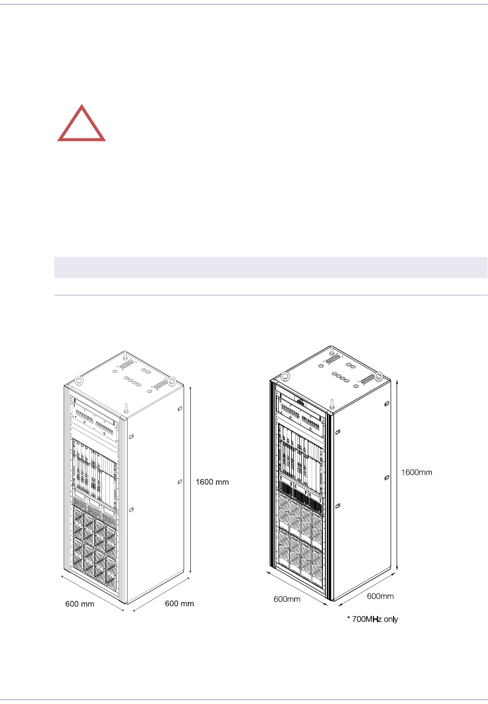
Table 2.1 and Figure 2.1 show the physical dimensions of the rack. These dimensions do not include
space for cabling, the insertion and removal of modules, or adequate airflow.
Figure 2.1
Rack Dimensions
!WARNING:Failure to meet the following requirements may result in personal
injury and cause damage to or destruction of the base station and surrounding equip-
ment.
Width Height Depth
Type-1 600 mm (23.6 inches) 1600 mm (63.0 inches) 600 mm (23 6 inches)
Table 2.1
Rack Dimensions

19 Part ####### revision 001 2006/8/3
Macro Base Station Installation Procedures (NPM2000)
Weight
The total weight of a full-sector base station is approximately 250 kg (560 pounds) (exclusive cables
and antennas). A dolly or crane is required to move the rack.
Table 2.2 shows the weight of the different base station components.
Floor Loading
Table 2.3 shows the floor loading for the base station.
NOTE:Floor-loading values are calculated as per Telcordia Technologies
GR-63-CORE.
Component Weight
Empty Rack 86 kg (189.6 pounds)
PDP 12 kg (26.5 pounds)
Digital Shelf (4 sector) 44 kg (97 pounds)
Radio Module Shelf (filled to capacity) 6.8 kg (15 pounds)
9.5 kg (20.9 pounds) … 700MHz only
Radio Module 11 kg (24.3 pounds)
12.4 kg (27.3 pounds) … 700MHz only
Table 2.2
Weight of Base Station Components
Version Floor Loading
MMDS 317.2 kg/m2 (64.6 pounds/foot2)
700MHz 338.8 kg/m2 (69.0 pounds/foot2)
1098 317.2 kg/m2 (64.6 pounds/foot2)
PCS TBD
WCS TBD
3.5GHz TBD
3.3GHz TBD
Table 2.3
Base Station Floor Loading

Site Preparation
2006/8/3 Part ####### revision 001 20
Torque Values
Table 2.4 shows the recommended torque values for the different sizes of fasteners used in the rack.
NOTE:Unless otherwise specified, torque tolerances are ±0.2 N•m (±1.8 inch-
pounds).
Fastener Size Recommended Torque
5/16 inch compression lug nuts on PDP 6.20 N•m (54.9 inch-pounds)
M5 screw 3.00 N•m (26.6 inch-pounds)
M4 screw 1.50 N•m ( 13.3 inch-pounds)
M3 screw 0.63 N•m (5.6 inch-pounds)
M2.5 screw 0.36 N•m (3.2 inch-pounds)
SMA connector 0.98 N•m (8.67 inch-pounds)
Type-N connector 0.98 N•m (8.67 inch-pounds) (hand-tightening)
2.45 N•m (21.7 inch-pounds) (hex-connector)
7/16 DIN connector 28.0 N•m (247.8 inch-pounds)
Radio Module thumb screws (M4 screw) 1.5 N•m (13.3 inch-pounds)
Power cable screws TBD N•m ( inch-pounds)
Table 2.4
Torque Values of Threaded Fasteners

21 Part ####### revision 001 2006/8/3
Macro Base Station Installation Procedures (NPM2000)
E
NVIRONMENTAL
R
EQUIREMENTS
Before you begin installing the base station, read the following environmental requirements. Ensure
that each requirement is met before proceeding with the installation and consult your MOPs
for procedures concerning building requirements, hazardous materials and waste,
and environmental systems.
Temperature
The base station is designed to be installed in a temperature-controlled environment.
Table 2.5 shows the ambient temperature requirements for the base station.
Humidity
The base station is designed to be installed in a humidity-controlled environment.
Table 2.6 shows the humidity requirements for the base station.
Altitude
Certain components in the base station are sensitive to altitude. Table 2.7 shows the altitude require-
ments for the base station.
!WARNING:Failure to meet the following requirements may result in personal
injury and cause damage to or destruction of the base station and surrounding equip-
ment.
Operational State Temperature Requirement
Operating +5°C to + 40°C (+41°F to +104°F)
Short-term operation (less than 96 hours / year) –5°C to + 50°C (+23°F to +122°F)
Storage –40°C to + 60°C (–40°F to +140°F)
Table 2.5
Temperature Requirements
Operational State Humidity Requirement
Operating 5% to 85%
Short-term operation (less than 96 hours / year9 5% to 90%
Storage 5% to 95%
Table 2.6
Humidity Requirements
Operational State Altitude Requirement
Operating –60 m to +1800 m (–197 feet to +5904 feet)
Table 2.7
Altitude Requirements

Site Preparation
2006/8/3 Part ####### revision 001 22
Airflow
The base station rack requires 600 mm of open space in front of and behind it to allow suitable airflow
for cooling.
Heat Output
Table 2.8 shows the amount of heat produced by the base station.
Configuration Heat Output (W) Heat Output (BTU / h)
1 sector 1392
1104 (700MHz)
4750
3767 (700MHz)
2 sector 2304
1728 (700MHz)
7862
5896 (700MHz)
3 sector 3216
2352 (700MHz)
10973
8025 (700MHz)
4 sector 4128
2976 (700MHz)
14085
10155 (700MHz)
Table 2.8
Heat Output

23 Part ####### revision 001 2006/8/3
Macro Base Station Installation Procedures (NPM2000)
E
LECTRICAL
R
EQUIREMENTS
Before you begin installing the base station, read the following requirements. Ensure that each require-
ment is met before proceeding with the installation.
Main Power
The base station requires a –48 V DC power supply.
The allowable DC input voltage at the PDP ranges from –46 V to –56 V. The input power noise level
should not exceed a maximum of 100 mV peak-to peak, DC to 20 MHz.
NOTE:The minimum gauge for the wires connecting the base station to the main
power source is #2 AWG. The maximum loop length of #2 AWG wire is 19.8 m. #2
AWG wire that is less than this length will not be damaged or overheat in the event of a
current overload or short-circuit condition.
Figure 2.2 shows the base satation’s power and grounding cabling.
Figure 2.2
Power and Grounding Cabling
!WARNING:Failure to meet the following requirements may result in personal
injury and cause damage to or destruction of the base station and surrounding equip-
ment

Site Preparation
2006/8/3 Part ####### revision 001 24
Table 2.9 and Table 2.10 shows the power consumption for the base station when receiving –48V DC
at the PDP.
Configuration Digital Shelf
(A) Fan Max Speed
(A) Radio Module
(A) Each Feed
(A) Total
(A) Total
(W)
1 sector FEED-A
FEED-B
83
9
9
20
20 29 1392
2 sector FEED-A
FEED-B 93 18
18
30
30 48 2304
3 sector FEED-A
FEED-B 10 3 27
27
40
40 67 3216
4 sector FEED-A
FEED-B 11 3 36
36
50
50 86 4128
Table 2.9
Power Consumption Values without Routers
Configuration Digital Shelf
(A) Fan Max Spped
(A) Radio Module
(A) Each Feed
(A) Total
(A) Total
(W)
1 sector FEED-A
FEED-B 83 6
6
17
17 23 1104
2 sector FEED-A
FEED-B 93 12
12
24
24 36 1728
3 sector FEED-A
FEED-B 10 3 18
18
31
31 49 2352
4 sector FEED-A
FEED-B 11 3 24
24
38
38 62 2976
Table 2.10
Power Consumption Values without Routers (700MHz)
NOTE:Each radio module draws 9A at –48V DC

25 Part ####### revision 001 2006/8/3
Macro Base Station Installation Procedures (NPM2000)
Figure 2.3
Power Consumption
Main Power Bay Circuit Breaker Size
The base station rack is connected to the main power bay by two power cables. The circuit breaker size
for the power supply should be 60A per feed to protect the power cables in the event of a current over-
load or short-circuit condition.Power Bay Ground and Voltage Levels
Table 2.11 shows the required electrical levels as measured at the PDP terminals.
RM-1M RM-1D
RM-2M RM-2D
RM-3M RM-3D
RM-4M RM-4D
FEED-A FEED-B
Digital Shelf
11A
9A
11A
9A
9A 9A
9A 9A
9A 9A
29A
48A
67A
86A
Unit Measurement Specification
Voltage –48V DC to return –48V DC nominal
(–46V DC to –56V DC)
Power –48V DC to return Dual Supply 2 kW maximum (each power supply)
Single Supply 5.3 kW maximum
Voltage Return to ground 0.5V DC maximum
Resistance Return to ground 0.1Ω maximum
Voltage –48V DC to ground –46 DC to –56V DC
Table 2.11
Required Ground and Voltage Levels

Site Preparation
2006/8/3 Part ####### revision 001 26
Base Station Circuit Breaker Current Loads
The rack contains a power distribution panel (PDP). The PDP has up to 18 circuit breakers (CBs).
Each breaker switch controls the power to a specific base station component. Individual base station
component can be powered off by setting the appropriate breaker switch to the OFF (down) position.
Table 2.12 shows the maximum current loading of the circuit breakers in the rack PDP.
Backup Power
The base station does not contain any internal battery backup systems. Ensure that your main power
source has a backup power system in case of a power failure.
Fuses
Each radio module contains one 30A, 250V, fast-blowing fuse to protect the RF components from
damage in the event of an electrical overload.
Rack Grounds
Table 2.13 shows the grounding requirements for each rack.
Circuit Breaker Circuit Breaker
CBA1 15A CBB1 15A
CBA2 15A CBB2 15A
CBA3 15A CBB3 15A
CBA4 15A CBB4 15A
CBA5 15A CBB5 15A
CBA6 15A CBB6 15A
CBA7 15A CBB7 15A
CBA8 15A CBB8 15A
CBA9 7.5A CBB9 7.5A
Table 2.12
Circuit Breaker Current Loads
Ground Type Requirement
Frame ground The rack requires one connection to its frame assembly for use as a frame ground. The
frame ground cable uses #6 AWG wire.
Main ground The rack requires one connection to the main building ground, such as the master
ground bar (MGB). The ground cable uses #6 AWG wire.
Table 2.13
Grounding Requirements

27 Part ####### revision 001 2006/8/3
Macro Base Station Installation Procedures (NPM2000)
Compression Lug Color Codes
Table 2.14 shows the compression lug color codes for common wire gauges.
Wire Gauge (AWG) Color Code
#6 (used for NPM2000 ground cables) Blue
#4 Gray
#2 (used for NPM2000 main and return power cables) Brown
#1 Green
1/0 Pink
2/0 Black
Table 2.14
Compression Lug Color Codes

Site Preparation
2006/8/3 Part ####### revision 001 28
N
ETWORK
AND
B
ACKHAUL
R
EQUIREMENTS
Before you begin installing the base station, read the following network requirements. See the follow-
ing documents for detailed information about network and backhaul requirements:
Network Deployment Planning Guide–describes site, network, and backhaul requirements.
System Overview–describes the role and function of equipment in the network core.
Edge Routers
The base station requires a 100-Mbit/s Ethernet connection to at least one edge router configured to
direct packets between the base station and the network core. Ensure that your base station site can
accommodate the electrical, environmental, and physical requirements of the edge routers.
Backhaul Circuits
Multiple T1, DS3/E3, or other interfaces connect the edge routers at the base station site to the net-
work core. See your field engineering package information about your site’s backhaul circuits and the
configuration of any necessary customer service units (CSUs).
NOTE:Backhaul circuits must be tested by qualified personnel before the base sta-
tion is placed into operation in order to ensure connectivity with the core servers
PSTN Gateway
The base station does not connect directly to the PSTN. A PSTN gateway located in the network core
connects the IP-based equipment to the circuit-switched PSTN.
NOTE:Ensure that any equipment connecting the base station to the PSTN is UL-
listed.

29 Part ####### revision 001 2006/8/3
Macro Base Station Installation Procedures (NPM2000)
General Site Requirements
Each site has unique requirements and characteristics. The field engineering package contains the site’s
floor plan, cabling routing and termination, and other site-specific.
Restricted Access
Access to the site must be controlled by the authority for that location and granted through the use of
special tools, locks and keys, or other means of security. Access should be limited to service personnel
who have been instructed about the reasons for the access restrictions and about any precautions that
must be taken while at the location.
Mounting Surface
The base station is suitable for mounting on concrete or other noncombustible surfaces only.
Equipment Entrance and Unloading Area
A route must be provided between the unloading area and the equipment room where no restrictions
will be encountered with a clearance less than 900 mm wide (side-to-side), and 2000 mm high (floor-
to-obstruction).
All turns along the route must allow sufficient clearance to turn or tilt an object 600 mm wide, 600
mm deep, and 1600 mm high.
AC Outlets
The site must have at least two duplex AC receptacles located within a convenient distance to facilitate
installation and maintenance of the base station.
Fire Protection System
It is recommended that a fire protection system is provided for the site.
Lighting
The site must have sufficient lighting to conduct work in a safe manner. Emergency lighting is recom-
mended. Lighting must meet local and other applicable regulations.
Tower Lights
Depending on its height and applicable regulations, the tower may require aviation safety lights. Con-
sult the aviation, environmental, and communication regulations applicable to your site for informa-
tion.
Antenna Mounting Locations
The base station uses two antennas (main and diversity) per sector.
Cabling Requirements
Ensure that your site has the necessary cable racks and ladders to accommodate the base station and
that your site has external cable access ports for the RF antenna cabling.

Site Preparation
2006/8/3 Part ####### revision 001 30
Isolated Ground Plane Environment
Ensure that the base station will be installed in an isolated ground plane environment as defined in
Telcordia Technologies GR-1275-CORE.
Master Ground Bar Requirements
The site’s master ground bar (MGB) must be connected to the building principal ground’s electrode
system. The building principal ground is the point where grounding conductors of the building (such
as air-conditioning, communication systems, and structure) are bonded together.
Ground Riser Cable
The ground riser cable (the cable connecting the MGB to the building principal ground) must have a
minimum conductor sizing of 2/0 AWG. If any equipment cables at the site are larger than 2/0 AWG
(such as to compensate for voltage drop), the size of the ground riser cable must be adjusted.
Ground Resistance
The resistance of the building principal ground shall be as low as possible. AN objective of 5Ω is a tele-
communications industry standard. In no case should resistance be allowed to exceed the local electri-
cal utility limits of 25Ω (NEC article 256-56).

2006/8/3 Part ####### revision 001 31
Chapter 3
Chapter 3
P
RE
-I
NSTALLATION
P
ROCEDURES
This chapter lists the tools and equipment required for installing and testing the equipment. It also
provides procedures for unpacking the rack and configuring individual cards and shelves.
Contents
Preparing for Installation ............................................................................................................................... 32
Antistatic Precautions ............................................................................................................................ 33
Equipment, Tools, and Supplies Checklists ........................................................................................... 35
Unpack the Equipment .......................................................................................................................... 37
Review Site Deliverables List ................................................................................................................ 38

Pre-Installation Procedures
2006/8/3 Part ####### revision 001 32
P
REPARING
FOR
I
NSTALLATION
This section describes precautions, equipment, and tasks that should be reviewed or performed prior
to beginning the NPM2000 base station installation.
Table 3.1 shows the topics described in this section.
Topics Page
Antistatic Precautions 33
Equipment, Tools, and Supplies Checklists 35
Unpack the Equipment 37
Review Site Deliverables List 38
Table 3.1
Pre-Installation Requirement

33 Part ####### revision 001 2006/8/3
Macro Base Station Installation Procedures (NPM2000)
Antistatic Precautions
To prevent damage to the base station components from static electricity:
Do not handle circuit boards unless you are using the appropriate antistatic protection, such
as wrist straps, boot straps, boots, or a conductive mat. Wrist straps must have snug but com-
fortable contact with your skin, and they must be connected to a grounding point on the
rack.
Handle circuit boards by the faceplate, handles, or edges. Do not touch any integrated cir-
cuits, connections, pins, or soldered surfaces.
WARNING:Components in the base station are highly sensitive to electrostatic
discharges (ESD). Follow the procedures described below to prevent unseen damage
from occurring.

Pre-Installation Procedures
2006/8/3 Part ####### revision 001 34
Wrist-Strap Grounding Point
The rack contains a wrist-strap grounding point in the bottom-left corner of the power distribution
panel (PDP). The grounding point is connected to the frame ground and provides antistatic protec-
tion when technicians work with circuit cards.
NOTE:The rack must be grounded for the wrist-strap grounding point to be effec-
tive.
Figure 3.1 shows the location of the Wrist-Strap grounding point to be connected to the frame
ground.
Figure 3.1
Wrist-Strap Grounding Point
F1

35 Part ####### revision 001 2006/8/3
Macro Base Station Installation Procedures (NPM2000)
Equipment, Tools, and Supplies Checklists
Tools
The following tools are recommended for a typical base station installation:
NOTE:Ensure that your torque wrenches are correctly calibrated according to the
methods and schedule specified by the manufacturer. The calibration date should be
indicated on each wrench.
Safety Equipment
The following safety equipment is recommended for a typical base station installation.
Allen key set Platform stepladder (6-feet)
Bolt cutter Plum bob
Cable ties Portable band saw kit
Chalk line Scissors
Drill bits (metal and masonry) Scratch awl
Electrical tape Shims (for leveling NPM2000)
Extension cord Socket sets (Imperial and metric)
Flat file Strap (with buckle)
Framing square Tape measures (linen and metal)
Hacksaw (with blades) Hammer drill
Torpedo level Heat gun (with heat shrink roll)
Torque wrenches Label maker
Wrench sets (imperial and metric) Marking pencil
Utility knife Oxide-inhibiting compound
Vacuum Cleaner with high-efficiency particulate air (HEPA) filter.
Ear plugs Flashlight
Electrical gloves Portable eye-wash station
ESD straps Safety glasses
First aid kit Safety shoes

Pre-Installation Procedures
2006/8/3 Part ####### revision 001 36
Test Equipment
Table 3.2 shows the equipment recommended for testing base station functionality.
NOTE:Ensure that your test equipment is correctly calibrated according to the meth-
ods and schedule specified by the manufacturer. The calibration date should be indi-
cated on each piece of test equipment.
Software
Table 3.3 shows the software recommended to be installed on your laptop or workstation.
Equipment
Digital multimeter Checking continuity and electrical characteristics.
Sunset OCx Testing SONET and T-carrier network and services.
Workstation, terminal, or laptop Installing, configuring, and verifying software.
Cable sweep generator Testing the electrical integrity of antenna and RF cables.
Spectrum analyzer Monitoring RF signal output.
Ethernet cable tester Testing the type and integrity of Ethernet cables
Oscilloscope Checking input power noise levels
Table 3.2
Recommended Test Equipment
Software Purpose
TCI/IP drivers Accessing the individual systems over TCP/IP
SSH, SCP Creating secure shell (SSH) sessions with the cards in the base station. For UNIX-like oper-
ating systems, you can type ssh at the command line. For Windows operating systems, use
putty.exe or another SSH client.
Secure copy (SCP) is required for transferring files securely across the network.
Telnet, FTP Establishing sessions and transferring files with devices in the network.
Serial terminal Communicating with management controllers, sector controllers.
Text editor Viewing and editing text and configuration files. Must support UNIX-style text files.
Web browser Displaying the Configuration Management (CM) tool and other Web-based tools
Table 3.3
Recommended Software

37 Part ####### revision 001 2006/8/3
Macro Base Station Installation Procedures (NPM2000)
Unpack the Equipment
The rack is delivered on shipping pallets. The rack is secured in an upright position and is bolted to
the pallet. Additional equipment is delivered in separate shipping boxes.
To unpack the base station equipment
1Transport the shipping boxes to the installation area using a dolly or pallet jack.
2Inspect the exterior packaging for any noticeable damage that may have occurred during shipment.
3Verify that the shipment is complete by checking the contents of each box against the bill of materials
(BOM) or shipping invoice that arrives with each box. The BOM for each box may be located on the out-
side or inside of the box.
4Report any missing or damaged components to the field support coordinator as soon as possible.
5Cut the packaging tape on each box using scissors or a utility knife.
6Remove the cardboard packaging from the rack:
iRemove the top of the cardboard packaging.
ii Remove the cardboard sides. The cardboard sides are bolted to the shipping pallet and pull off with
minimal effort.
7Remove the protective bags covering the rack.
8Check the rack for extra mounting hardware or invoices. If there are additional items, remove them and
keep them for future use.
9Verify the contents of the other boxes by examining their BOMs.
NOTE:Do not remove any items from their antistatic bags until you are ready to
install them.
10 Save the packaging material and the BOMs in case any of the equipment needs to be returned or moved
in the future.

Pre-Installation Procedures
2006/8/3 Part ####### revision 001 38
Review Site Deliverables List
Table 3.4 shows the paperwork that ships with each base station.
To check the inventory
1Perform an inventory check using the site deliverables list provided with the TBD package and BOMs.
2Ensure that all equipment and accessories have been shipped.
3Document any shortages and report them to the field support coordinator so that any missing equipment
may be produced and delivered to the site as soon as possible.
4Ensure that the serial number for each piece of equipment is recorded in the base station’s on-site docu-
mentation.
Document Description
Anchor kit Lists installation kit contents
BOM Lists every component in the base station
Shelf inspection checklist Factory inspection of each utility and radio shelf
Table 3.4
Inventory Checklists