Sanyo Electric Co PBS-CS102 PHS Cell Station User Manual
Sanyo Electric Co Ltd PHS Cell Station
manual

SANYO
PHS Cell Station
March 19, 2004
- User’s Manual -

1
Table of Contents
Installation conditions ............................................................................................................ 2,3
Fixing antenna for PBS-CS102 ................................................................................................. 4
Condition of the antenna cable (PBS-CS102) .......................................................................... 5
Terminal block appearance ...................................................................................................... 6
Notes at the time of lid opening and closing ............................................................................ 7
Connection of the power cable ......................................................................................... 8,9,10
Connection of the line cable .......................................................................................... 11,12,13
Concerning the installation of cable ....................................................................................... 14
Warning ................................................................................................................................... 15
Appendix (1), (2) ................................................................................................................. 16,17

2
Installation conditions
]Place
\CS shall be installed in the place where the public can not easily access.
\Installation place shall have the structure which can support the weight of CS
and its fixing facilities.
\Installation place shall be flat with no inclination.
\If CS is installed in the place where it may drop down, it shall be provided
with protective measure against the drop.
\There shall be no object around 2m of CS.
\For the maintenance use, there shall be the space in about 500mm around the
stand.
\CS shall be installed in the direction that the logo plate appears upwards. CS
can be placed in vertical direction with arranging the fixing metal.

3
Installation conditions
]Antenna
\With fixing antennas, there shall be enough viewing angle from CS. (Target
angle: vertical: 30 degree or more, horizontal: 330 degree or more)
]ISDN Line
\Interconnection box for ISDN line shall be available near the CS.
\ISDN line length from the exchange to CS and its quality shall comply with
the technical standard (ANSI T1.601-1992).
]Power supply
\AC120V shall be available with easy wiring connection work.
4
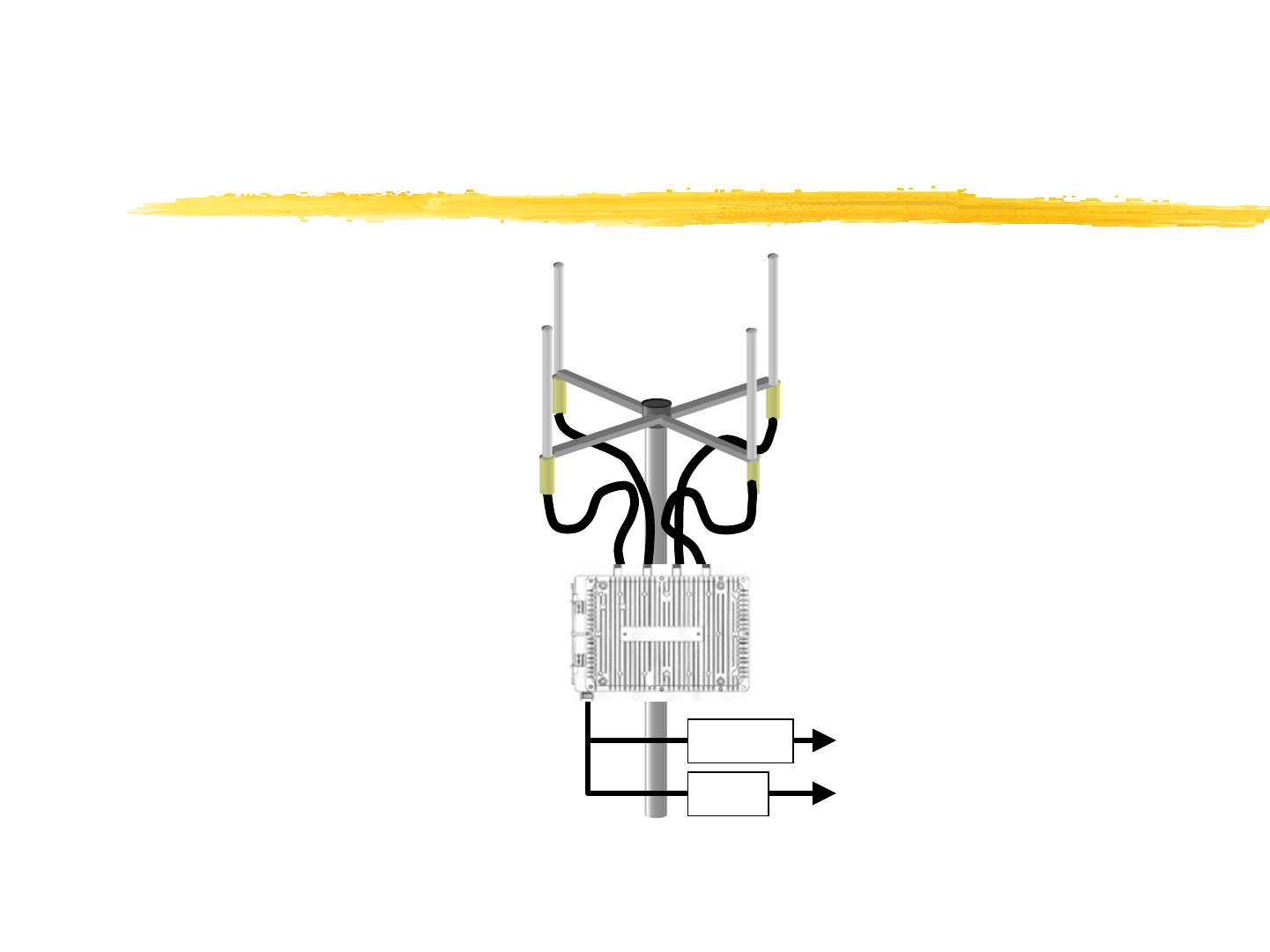
Fixing antenna
for PBS-CS102
To ISDN Line
AC120V
MDF
Breaker
PBS-CS102
5
Condition of the antenna cable
(PBS-CS102)
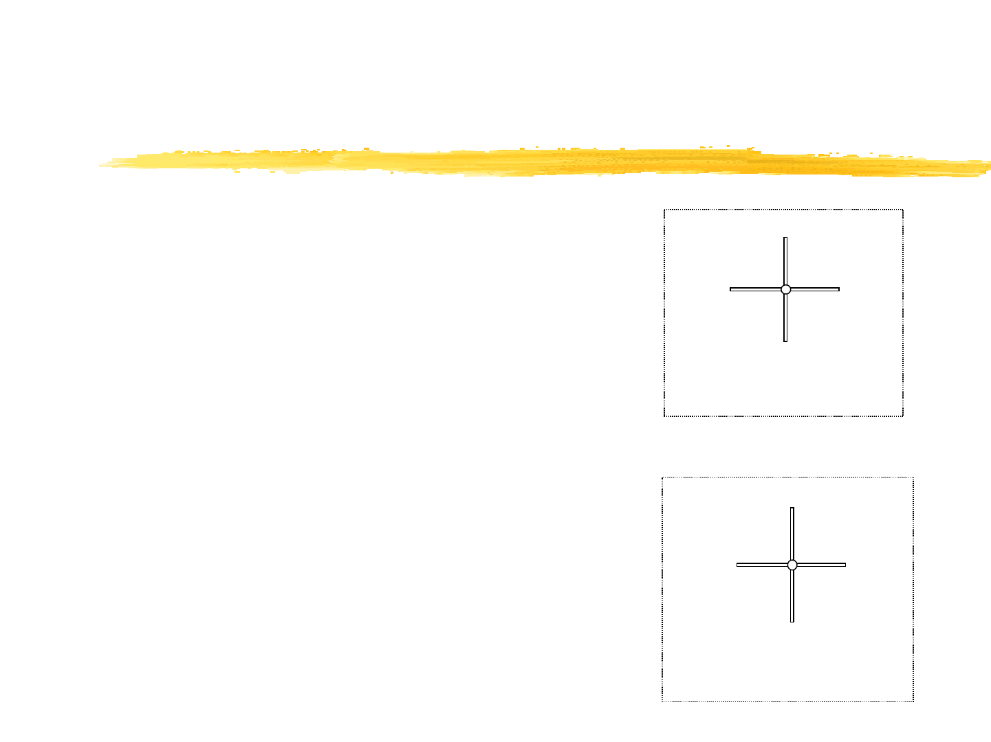
]Numbering arrangement
\Numbering arrangement of 1 - 4 shall be made
clockwise or counterclockwise.
]Tightening torque of the antenna cable:
7 - 12 Kgf-cm.
]Wind the self-bonding tape between the
antenna connector and the end of cable.
1
2
3
4
1
2
3
4
Case of Clockwise
Case of Counterclockwise
6
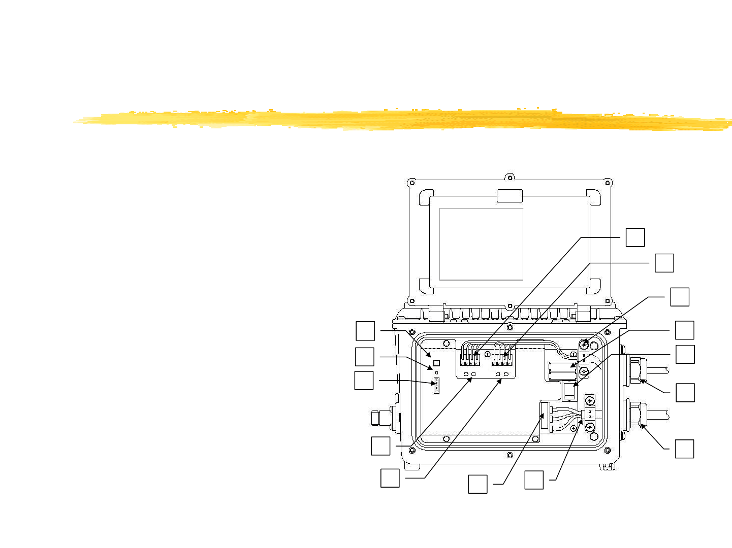
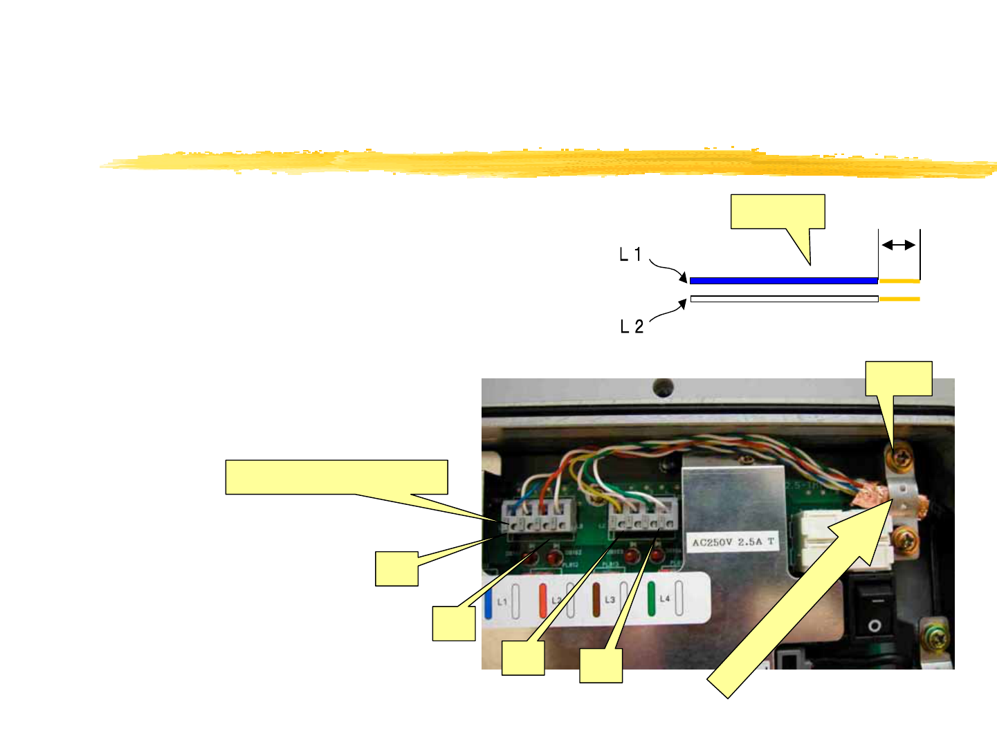
Terminal block appearance(PBS-CS102)
]Terminal block of the power supply and line’s connections are shown below
1: Status indications LED
2: Reset Switch
3: Maintenance terminal connector
4,5: Line Status LED
6: Power supply Terminal
7: Earth clamp for Power cable
8: Cable gland for power cable
9: Cable gland for Line cable
10: Power supply switch
11: Fuse
12: Earth clamp for Line cable
13,14: Line terminal connector
1
2
3
4
567
8
9
10
11
12
13
14
7
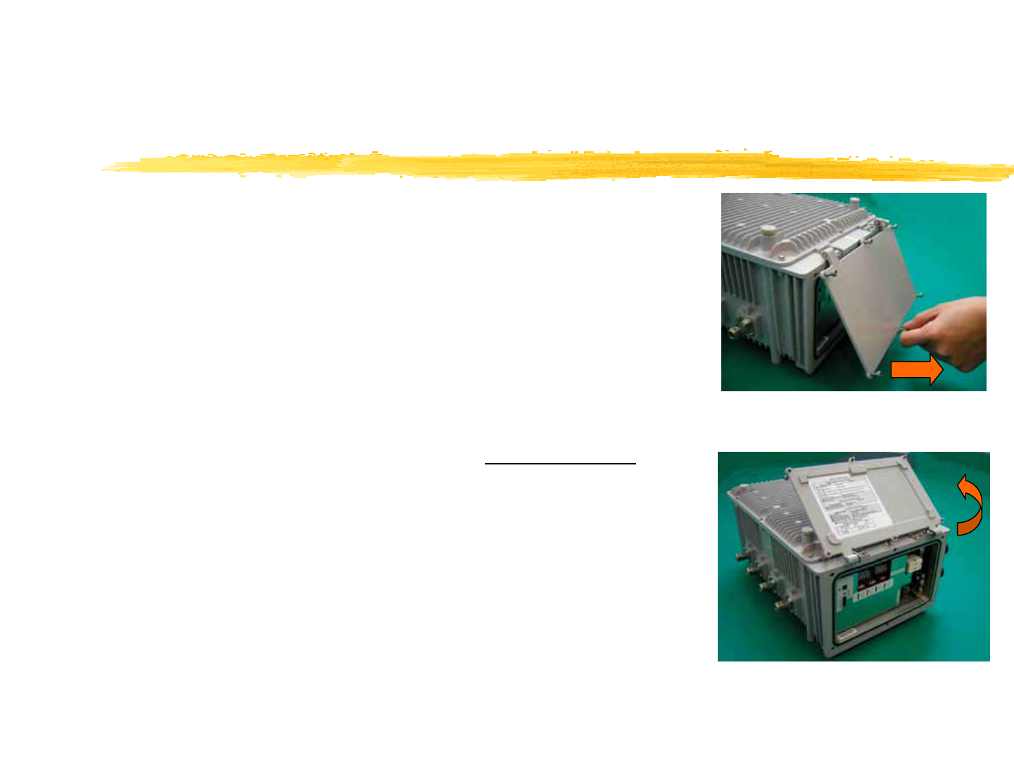
Notes at the time of
lid opening and closing
]Opening
\After loosening all lid’s fixation screws completely, pull
lower part and central screw of the lid, and slide. (Photo1)
\Confirm that all screws are free completely and two pins of
the lid is at the right edge of two metal fittings ,therefore
rotate the lid while pulling in the direction”an arrow” like
below . (Photo2)
]Closing
\Tightening torque of Cap screw: 10 - 15 Kgf-cm
\Tighten with M4 hexagon Socket Cap screws. (Cap screw).
\Tighten 6 screws equally and well balanced, after confirming
that the waterproof packing is nonexistent between the lid
and the CS.
[Caution1] If the clamp face or waterproof packing is scarred
by screw’s cusp, the waterproof performance may not be
obtained.
(Photo1)
(Photo2)
8
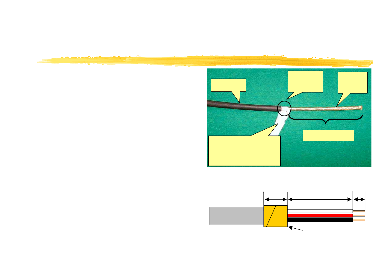
Connection of the power cable (1)
1) Reeve the cable from the cable gland nut
into the lid.
2) Pull the cable out to enough length that
the tip of the cable can be processed.
3) Peel the covering of the cable. (Photo 3)
4) Peeling off core line.
5) Loosen the copper shield and wind it
onto the core wire’s tip 4 turns or more.
(Photo3)
Copper
shield
Covering
end
Covering
70 - 90mm
interposition material:
Cut it at
the covering’ root.
(figure)
8 - 9mm
60 - 80mm
15mm
Copper shield
*The cable color is generally used in Japan, and it
used in U.S.A. shall comply with the local
specifications.
9
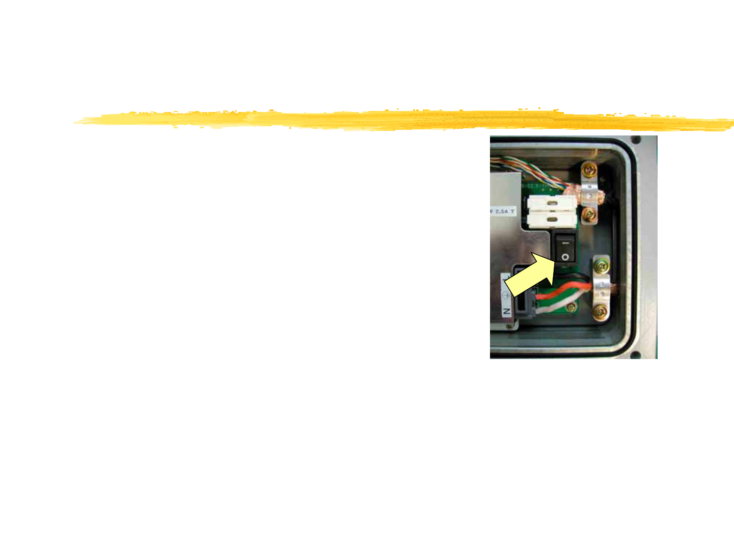
Connection of the power cable (2)
6) Turn the Power supply switch off.(Photo4)
\Push the power supply switch at "○"side to turn it
off.
\[Caution] When pushing the power switch at "-"
side, CS is turned on.
(photo4)
Push
10
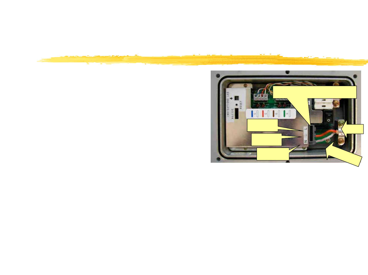
Connection of the power cable (3)
7) Feazings processing of the core line.
\Pressing the black portion of the connector
with a minus screwdriver(φ6) or a plus
screwdriver(φ4) , insert a core wire.
\L (Loading), N (Neutral), FG (Frame Ground).
8) Combine the copper shield to the position
“FIX” of Photo 5. And tighten the cable
gland firmly.
\[Caution]If the fixation of the terminal
block’s lid is imperfect, it is feared that this
CS gives hindrance to other electric devices.
N:White
FG:Red
L:Black
Forming
(photo5)
9) Form core wires that are inserted into the power supply terminal.
10) The tightening of the dome nut must be done by hand without fail and
tighten it strongly.
11) Wind the self-bonding tape between the surface of dome nut and the end of
cable.
Fix
Press with a screwdriver
11
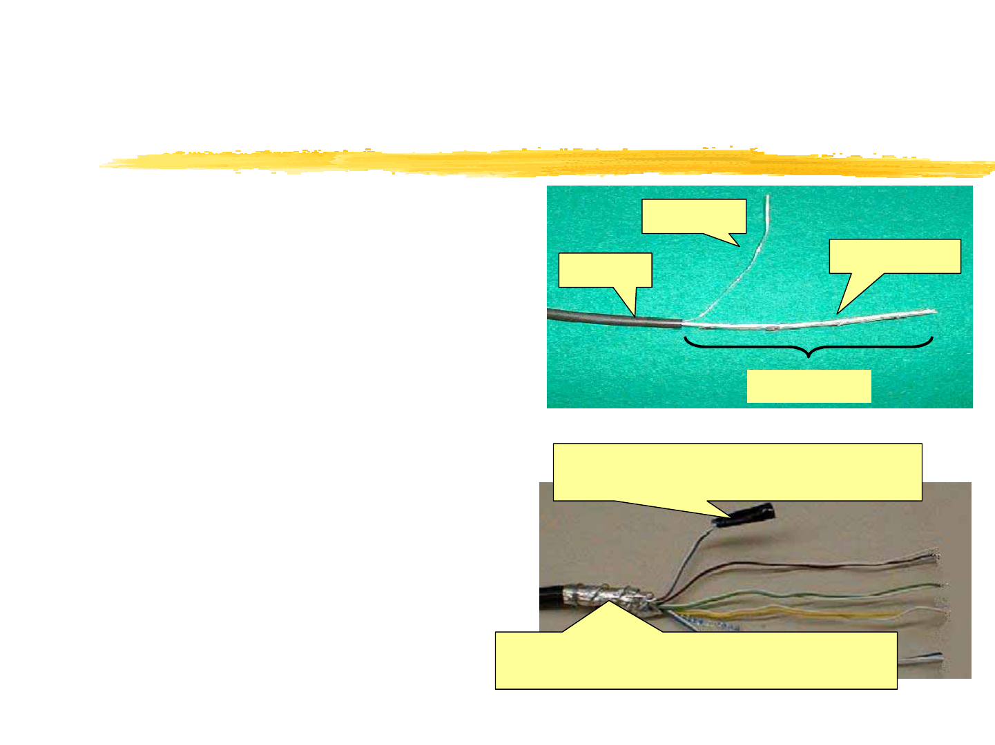
Connection of the line cable (1)
1) Reeve the cable from the dome nut into
the lid.
2) Pull the line cable out to enough length
that the tip of the cable can be
processed.
3) Peeling off the line cable covering.
(Photo 6)
\Peel off the covering of the line cable. The
length of the line cable is 100 - 120 mm.
(Photo 6)
4) Loosen the shield and wind it on the
heart line of covering 4 turns or more.
(Photo 7)
(photo6)
(photo7)
Shield tape
Drain wire
Covering
130 - 140mm
Wind the aluminum shield, and
furthermore wind drain wire here too.
Process the end of the line wire, which are
not used, with the suiting tape.
12
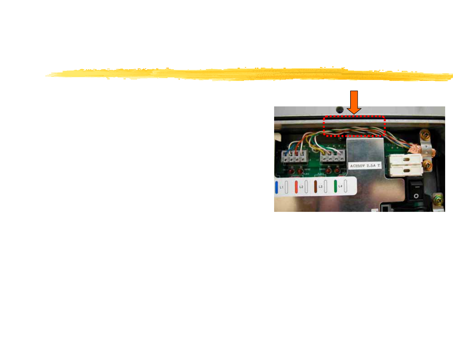
Connection of the line cable (2)
5) Loosen these four pair lines, peel off
core lines.(Figure)
6) Feazings processing of the core line.
\Pressing the button of the connector
with a minus screwdriver(φ3), insert a
core wire. (Photo8)
(Figure)
(photo8)
Pair lines
screw
L1
L2
L3 L4
Ground clamp for the Line
8mm
Press with a screwdriver
13
Connection of the line cable (3)
7) Form core wires that are inserted into
the line connector.
\Form the line cable as not touching on the
block. (Photo 9)
\Pay attention that the line cable does not
touch on the packing .
8) Tighten the dome nut.
9) Wind the self-bonding tape between the
surface of dome nut and the end of
cable.
(photo9)

14
Concerning the installation of cables
]Ground earth terminal of the power cable securely
In case that ground does not executed, there is the possibility that destroys the CS.
Because the surge protection by the ground wire can not perform.
]The earthing less than 10ohm (Class A) is desirable.
There is the possibility that the obstacle occurs to sounds and pictures of other radio
devices, when the earthing resistance becomes high.
]Separation distance between cables
Distance (generally 20 cm or more) shall be kept between the line cable and the power
cable for secure installation.
]The shield processing of the cable (maintenance box & breaker box)
Earthing must be executed as for the breaker box.
]Installation of lightening facility
Specifications of the CS do not specify the requirement for the installation of lightning
conductor. Don't connect the lightning cable to FG of the power supply.

15
WARNING!
FCC RF EXPOSURE COMPLIENCE
]To satisfy the FCC RF exposure requirement, a minimum
separation distance of 0.65m must be maintained between
the nearby person and radiating elements.
]Unauthorized alteration, modifications or attachments could
impair its quality, damage the cell station, or result in
violation of FCC regulations.

16
Appendix1:Installation materials (for example)
]Materials Quantity
PBS-CS102
Antenna 4
Coaxial cable 4
Power supply cable 1
Line cable 2pair
Stand 1set
Antenna pole 1
Antenna Arm 4
Arm fixing block 1
Self-bonding tape as adequate
Tie band as adequate
17
Appendix2:Cable specifications
Kinds Usage Specifications Remarks
Coaxial cable Antenna -
PHS cell
station
8D-SFA (connector with one-side N style (P))
MAX: 6m
Accessory of
the antenna
Power cable PHS cell
station -
power
supply
b
reaker box
With the 2.0mm2 , 3 cores with the copper shield
tape
Outsize diameter : 8.5 – 13.5 Ø
Frameresisting: PE cable
The color is designated.
(black, white, green and red)
Power cable
the equivalent
to the existing
cell station
Line cable Cell station -
Maintenance
box
Single line: Ø 1.0mm-4 pairs
A category 4 or more with aluminum or copper
shield tape
(Shield material 0.05t over)
Outsize diameter : 5 – 10 Ø
Flame resisting: PE cable
Line cable
The equivalent
to the existing
cell station