Sanyo Electric Co PBS-CS82 Radio Cell Station for the PHS WLL System User Manual
Sanyo Electric Co Ltd Radio Cell Station for the PHS WLL System
UserManual.wiki
>
Sanyo Electric Co
>
PBS CS82 User Manual
User Manual
Navigation menu
Upload a User Manual
Namespaces
Wiki Guide
HTML
PDF
Info
Views
User Manual
Discussion / Help
Navigation
![2Installation conditions]Place\CS shall be installed in the place where the public can not easily access.\Installation place shall have the structure which can support the weight of CSand its fixing facilities.\Installation place shall be flat with no inclination.\If CS is installed in the place where it may drop down, it shall be providedwith protective measure against the drop.\There shall be no object around 2m of CS.\For the maintenance use, there shall be the space in about 500mm around thestand.\CS shall be installed in the direction that the logo plate appears upwards. CScan be placed in vertical direction with arranging the fixing metal.](https://usermanual.wiki/Sanyo-Electric-Co/PBS-CS82/User-Guide-424554-Page-3.png)
![3Installation conditions]Antenna\With fixing antennas, there shall be enough viewing angle from CS. (Targetangle: vertical: 30 degree or more, horizontal: 330 degree or more)]ISDN Line\Interconnection box for ISDN line shall be available near the CS.\ISDN line length from the exchange to CS and its quality shall comply withthe technical standard (ANSI T1.601-1992).]Power supply\AC120V shall be available with easy wiring connection work.](https://usermanual.wiki/Sanyo-Electric-Co/PBS-CS82/User-Guide-424554-Page-4.png)
![4Fixing antenna for PBS-CS82 (case 1)To ISDN LineAC120VMDFBreaker]In case of vertical separate distance betweenantennas: 15cm or moreAngle between arms : 0 degreeVertical separate distancebetween antennasAngle between arms:0 degreeTop view](https://usermanual.wiki/Sanyo-Electric-Co/PBS-CS82/User-Guide-424554-Page-5.png)
![5Fixing antenna for PBS-CS82 (case 2)]In case of vertical separate distance betweenantennas: less than 15cmAngle between arms : 45 degreeHorizontal separate distance betweenantennas: 40cm or more.Angle between arms:45 degreeTop viewHorizontal separate distance > 40cmTo ISDN LineAC120VMDFBreaker* If horizontal separate distance is less than 40cm,the performance is reduced](https://usermanual.wiki/Sanyo-Electric-Co/PBS-CS82/User-Guide-424554-Page-6.png)
![6Connection of the antenna cable(PBS-CS82)]Order of cable connection\Antenna connector 1 - 4 : upper side\Antenna connector 5 - 8 : lower side]Numbering arrangement\Numbering arrangement of 1 - 4 and 5 - 8shall be made clockwise orcounterclockwise.]Tightening torque of the antenna cable:7 - 12 Kgf-cm.]Wind the self-bonding tape between theantenna connector and the end of cable.1234Upper sideantenna5678Lower sideantenna12345678Upper sideantenna Lower sideantennaCase of Clockwise(Case1)Case of Counterclockwise(Case2)](https://usermanual.wiki/Sanyo-Electric-Co/PBS-CS82/User-Guide-424554-Page-7.png)
![7Terminal block appearance(PBS-CS82)]Terminal block of the power supply and line’s connections are shown below1:Cable gland for power cable2:Cable gland for Line cable3:Earth clamp for Power cable4:Power supply Terminal(L)5:GND Terminal(FG)6:Power supply Terminal(N)7:Earth clamp for Line cable8,13,14,19:Line check terminal connector9,11,16,17:Line Status LED10,12,15,18:Line terminal connector20:Status indications LED21:Maintenance terminal connector22:Reset Switch23:Status indications LED Label24:GPS indications label for GPS model](https://usermanual.wiki/Sanyo-Electric-Co/PBS-CS82/User-Guide-424554-Page-8.png)
![8Notes at the time oflid opening and closing]Opening\After loosening all lid’s fixation screws completely, pullupper part and central screw of the lid, and slide. (Photo1)\Confirm that all screws are free completely and two pins ofthe lid is at the right edge of two metal fittings ,thereforerotate the lid while pulling in the direction”an arrow” likebelow . (Photo2)]Closing\Tightening torque of Cap screw: 10 - 15 Kgf-cm\Tighten with M4 hexagon Socket Cap screws. (Cap screw).\Tighten 6 screws equally and well balanced, after confirmingthat the waterproof packing is nonexistent between the lidand the CS.[Caution] If the clamp face or waterproof packing is scarred byscrew’s cusp, the waterproof performance may not beobtained.(Photo1)(Photo2)](https://usermanual.wiki/Sanyo-Electric-Co/PBS-CS82/User-Guide-424554-Page-9.png)
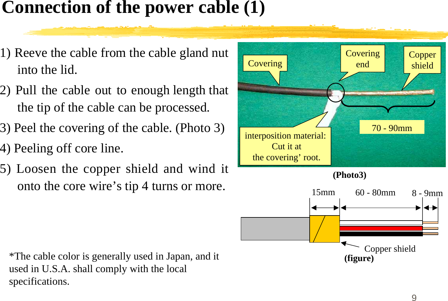
![10Connection of the power cable (2)6) Feazings processing of the core line.\Push the upper part of the connector with afinger, and insert a core wire. (figure)\L (Loading), N (Neutral), FG (Frame Ground).7) Combine the copper shield to the position“FIX” of Photo 5. And tighten the cablegland firmly.\[Caution]When the fixation of the terminalblock’s lid is imperfect, it is feared that thisCS gives hindrance to other electric devices.8) Form core wires that are inserted into thepower supply terminal.9) The tightening of the dome nut must bedone by hand without fail and tighten itstrongly.10) Wind the self-bonding tape between thesurface of dome nut and the end of cable.(figure)N:White FG:Red L:BlackFixForming(photo5)](https://usermanual.wiki/Sanyo-Electric-Co/PBS-CS82/User-Guide-424554-Page-11.png)
![14Concerning the installation of cables]Ground earth terminal of the power cable securelyIn case that ground does not executed, there is the possibility that destroys the CS.Because the surge protection by the ground wire can not perform.]The earthing less than 10ohm (Class A) is desirable.There is the possibility that the obstacle occurs to sounds and pictures of otherradio devices, when the earthing resistance becomes high.]Separation distance between cablesDistance (generally 20 cm or more) shall be kept between the line cable and thepower cable for secure installation.]The shield processing of the cable (maintenance box & breaker box)Earthing must be executed as for the breaker box.]Installation of lightening facilitySpecifications of the CS do not specify the requirement for the installation oflightning conductor. Don't connect the lightning cable to FG of the powersupply.](https://usermanual.wiki/Sanyo-Electric-Co/PBS-CS82/User-Guide-424554-Page-15.png)
![15WARNING!RF exposure installation instruction]To satisfy the FCC RF exposure requirement, aminimum separation distance of 4 feet must bemaintained between the nearby person and radiatingelements.]Unauthorized alteration, modifications orattachments could impair its quality, damage the cellstation, or result in violation of FCC regulations.](https://usermanual.wiki/Sanyo-Electric-Co/PBS-CS82/User-Guide-424554-Page-16.png)
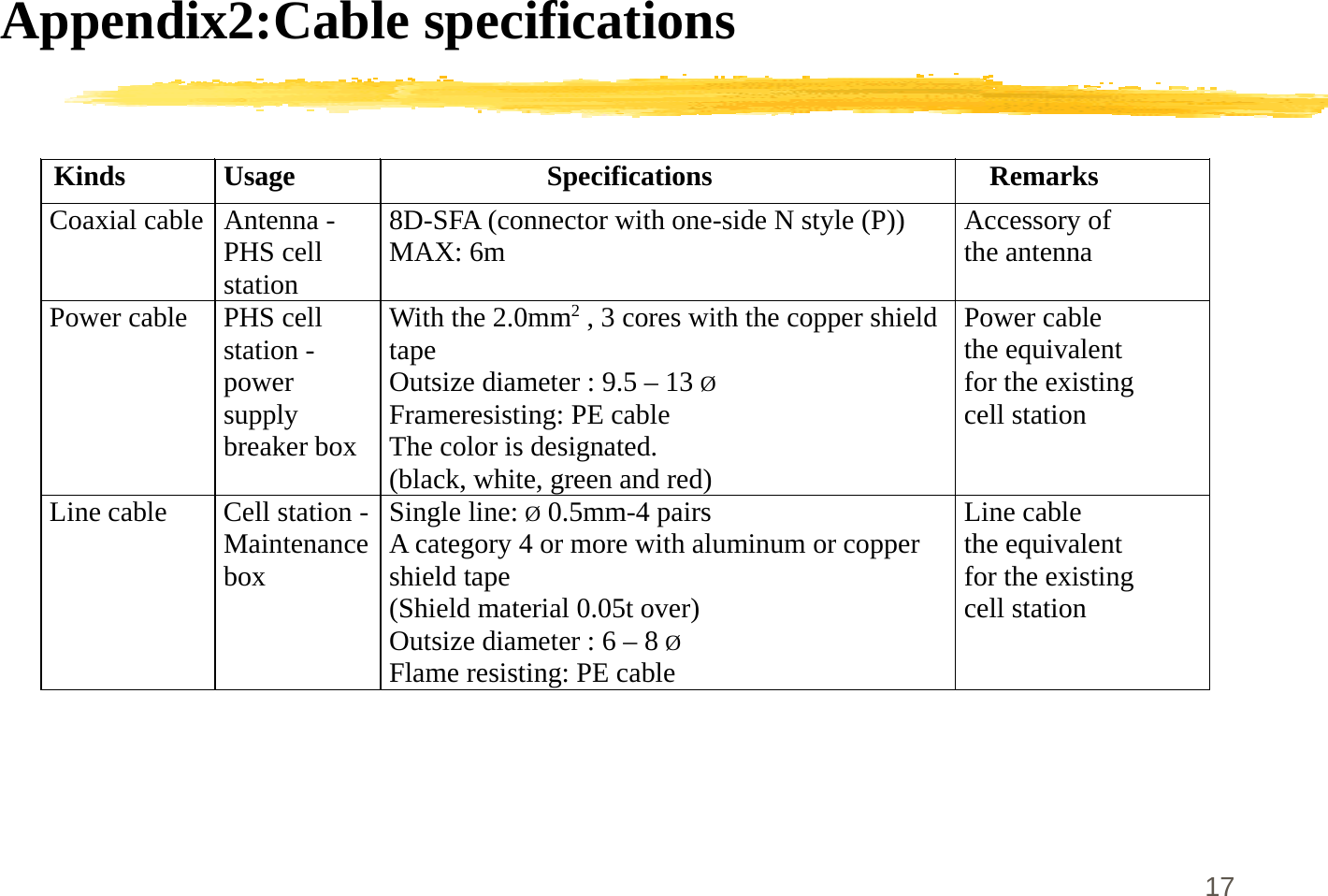
![16Appendix1:Installation materials (for example)]Materials Quantity PBS-CS82Antenna 8Coaxial cable (upper) 4Coaxial cable (lower) 4Power supply cable 1Line cable 4pairLine connector 4Stand 1setAntenna pole 1Antenna Arm 8Arm fixing block(upper) 1Arm fixing block(lower) 1Self-bonding tape as adequateTie band as adequate](https://usermanual.wiki/Sanyo-Electric-Co/PBS-CS82/User-Guide-424554-Page-17.png)