Sanyo EM C120 1 User Manual To The 2f2658e7 B806 4657 B241 8c6004f85999
User Manual: Sanyo EM-C120 to the manual
Open the PDF directly: View PDF ![]() .
.
Page Count: 20

FORM # EM-C120 (02/05)
SERVICE MANUAL SUPPLEMENT
for Model EM-C120
Microwave Oven
CAUTION
WARNING TO SERVICE
TECHNICIANS
PRECAUTIONS TO BE OBSERVED BEFORE AND DURING
SERVICING TO AVOID POSSIBLE EXPOSURE TO
EXCESSIVE MICROWAVE ENERGY
(a) Do not operate or allow the oven to be operated with the door open.
(b) Make the following safety checks on all ovens to be serviced before activating the magnetron or other
microwave source, and make repairs as necessary:
(1)Interlock operation, (2) proper door closing, (3) seal and sealing surfaces (arcing, wear, and other
damage), (4) damage to or loosening of hinges and latches, (5) evidence of dropping or abuse.
(c) Before turning on microwave power for any service test or inspection within the microwave generating
compartments, check the magnetron, wave guide or transmission line, and cavity for proper alignment,
integrity, and connections.
(d) Any defective or misadjusted components in the interlock, monitor, door seal, and microwave generation
and transmission systems shall be repaired, replaced, or adjusted by procedures described in this manual
before the oven is released to the owner.
(e)(i) A microwave leakage check to verify compliance with the Federal performance standard should be
performed on each oven prior to release to the owner. (For U.S.A)
(e)(ii) A microwave leakage check to verify compliance with the Canadian Regulation, HEALTH AND WELFARE,
SOR/79-920 should be performed on each oven prior to release to the owner. (For CANADA)
SUPPLEMENT OF
SERVICE MANUAL Microwave Oven EM-C160US
REFERENCE NO.SM-640180
See the Service Manual of EM-C180US(SM-640179)
except the items described in this Service Manual.
PRODUCT CODE NO. 437-453-00
CAUTION
For microwave energy emission
On every service call. A check for micro-
wave energy emission must be made
according to the following manner.
Measurement of energy emission
Measurement must be made with the microwave oven
operating at its maximum output and containing a load
of 275±15 milliliters of tap water initially at 20°±5°
celsius (68±9°F) placed within the cavity at the center.
NOTE:The water container must be a 600 milliliter bea-
ker and made of an electrically none conduc-
tive material such as glass or plastic.
The cook tray must be in place when measuring
emission.
A properly operating door and seal assembly will nor-
mally register emission no greater than 4 mW/cm2 to
allow for measurement uncertainty with the cooking
shelf or tray in place.
All repairs must be performed in such a
manner that microwave energy emission
is minimal.
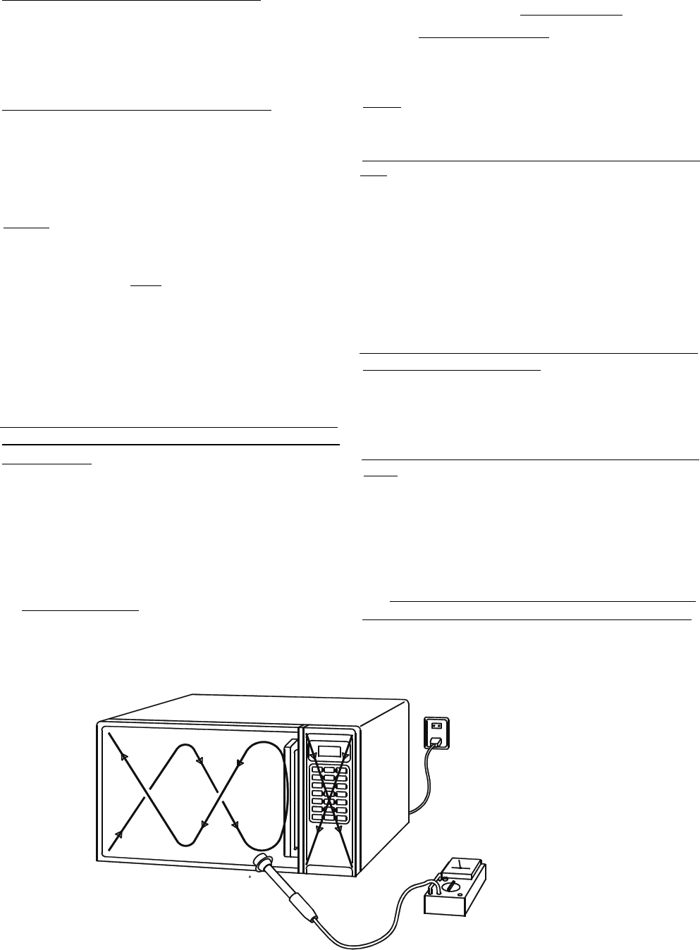
Follow the instructions supplied with the detector be-
ing used and perform an R.F. emission test around the
door front, and all edges and vent of the outer case.
The cabinet (wrapper) must be in place and the oven
fully assembled.
When performing an emission survey, with the meter
on FAST RESPONCE, the movemtnt of detector probe
shall not exceed one (1) inch per second.
In the area emitting the highest reading, switch the
meter to SLOW RESPONSE and take a reading for
minimum of three (3) seconds. We recommended the
pattern outline shown below when the door surface is
surveyed.
NOTE: Periodically check to be sure that the probe tip
is not worn or dirty.
The following U.S. standard applies to microwave ov-
ens:
21 CFR 1030.10, Performance Standard for Microwave
Ovens.
It requires that the power density of the microwave
radiation emitted by a microwave oven shall not ex-
ceed five (5) milliwatts per square centimeter at any
point 5 centimeters (about 2 inches) or more from the
external surface of the oven.
All microwave ovens exceeding the emission level of 4
mW/cm2 must be reported to Dept. of Service for mi-
crowave ovens and the manufacturer immediately .
The owner should be told not to use the microwave
oven until it has been repaired completely.
If a microwave oven is found to operate with the door
open, report to Dept. of Service, the manufacturer and
CDRH* immediately. Also tell the owner not to use the
oven.
*CDRH: Center for Device and Radiological Health.
The interlock monitor switch acts as the final safety
switch protecting the customer from microwave radia-
tion. If the interlock monitor switch operates properly
and the door interlocs switch fails, the fuse will blow.
If this happens, all interlock switches must be replaced.
The contacts of the interlock switches may be welded
together.

- 1 -
1. SPECIFICATIONS
Microwave output ................1,200W to 120W
Frequency ........................... 2,450MHz
Power supply ....................... 120V, 60Hz
Rated current ......................15 Amp.
Safety Device ......................
Thermal protector(Magnetron)
150°C(270°F) Open
(Thermostat) 80°C(144°F)Close
Thermistor (Magnetron) 200°C(360°F) Open
108°C(194°F)Close
Thermistor(Duct)................120°C(216°F) Open
Fuse (Cartridge Type) ................. 250V 10A
Micro switch, Relay
Interlock Switch
Interlock monitor Switch
Door sensing Switch and
Relay RL-3 and RL-4
Max. input time....................Electronic Digital, up to
Manual
10min./Memory 30min.
Overall Dimensions........422(W)x540(D)x335(H) mm
Oven cavity size ............330(W)x330(D)x230(H) mm
Effective Capacity of Oven Cavity.........19.1liters
Net weight ........................... 29Kg
NOTE: The power output specification, 1200W on this
model is measured with IEC measurement. The power
output is measured with two(2) liters water is equiva-
lent to 1200W in measurement with IEC, when mea-
sured with the following power output.
(1)1. Fill two beakers, one liter of tap water respec-
tively
2. Use an accurate thermometer and measure each
water temperature respectively.
(2) Place beakers side by side in center of the
ceramic tray.
(3) Close the door,set the “TIME” for two minutes.
Touch the “START” key and heat the water for
exactly two minutes.
(4)Take the beakers out, immediately stir the water
and measure the water temperatures respectively.
(5) Calculate the temperatures rise of water in each
beaker. Then calculate the average value of the two
temperature rises.(Ģt)
(6) The teperature rise shall be in the following range;
Average Temp. Rise
Minimum 15.4°C
Maximum 18.8°C
Power output is affected by the line voltage under load.
(7) For correct Power output measurement, the line
voltage under load must be 120±2 Volts.
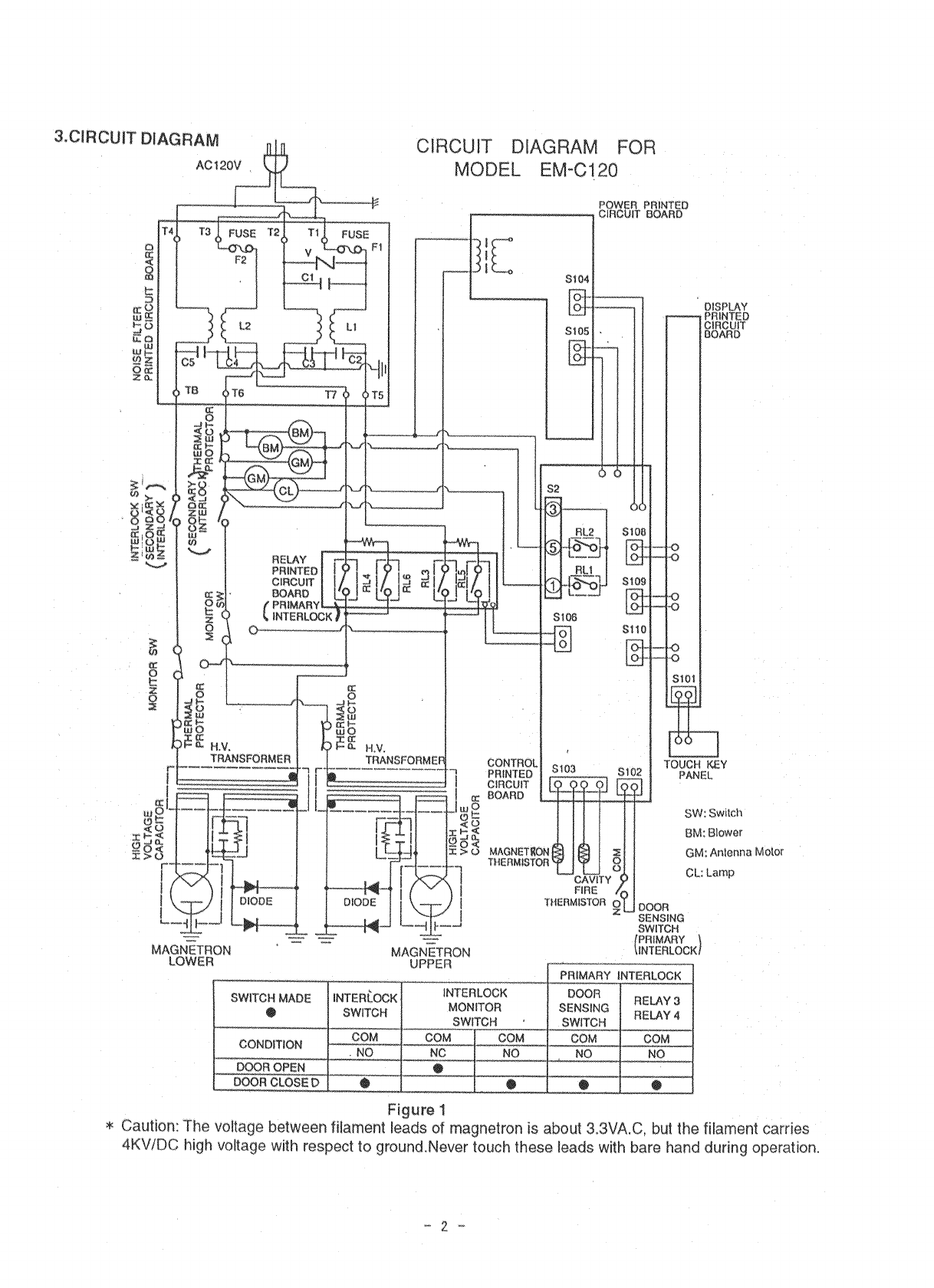
2. POWER OUTPUT MEASUREMENT
Power output Measurement ...................................... 1
Precautions and Repair Service Tips ....................... 1
Circuit Diagram ......................................................... 2
Test Procedures ............................................3
Disassembly Instructions............................... 3 •`4
Exploded View and Parts List......................... 5 •`12
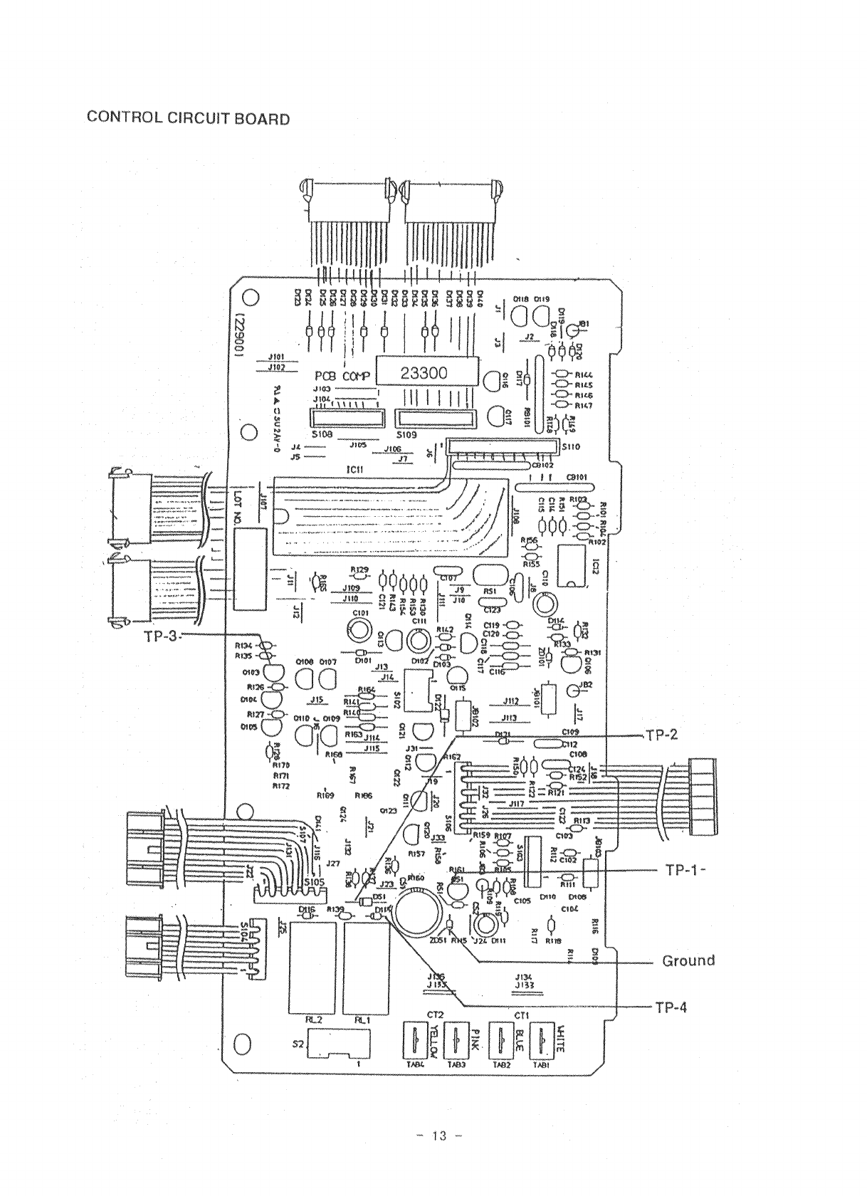
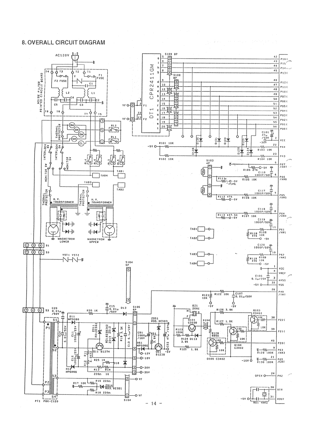
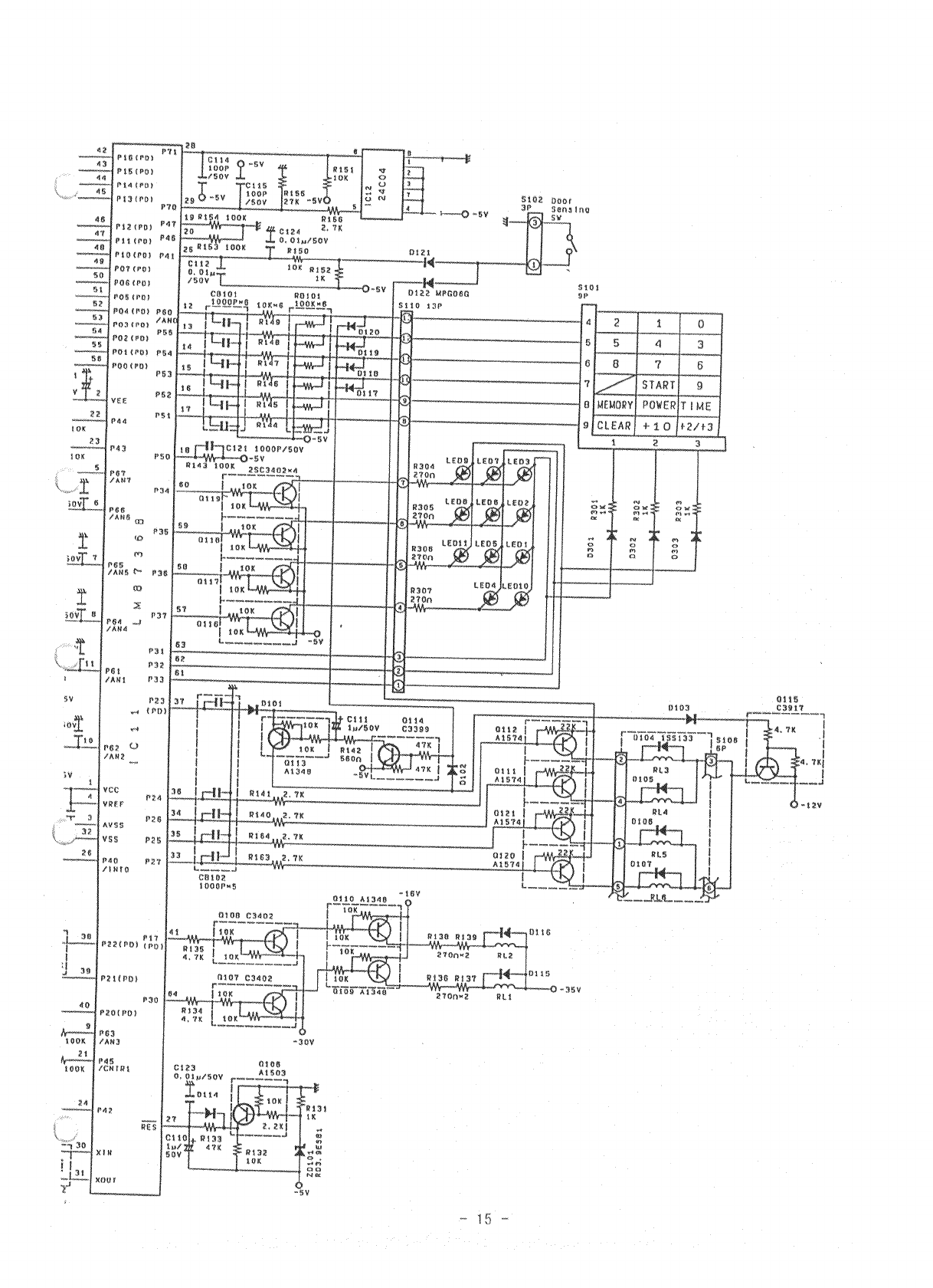
Overall Circuit Diagram.................................13 •`16
- 3 -
4. TEST PROCEDURES AND TROUBLESHOOTING
CAUTION
-DISCONNECT THE POWER SUPPLY CORD FROM THE WALL
OUTLET WHENEVER REMOVING THE CABINET FROM THE UNIT.
PROCEED WITH TESTS ONLY AFTER DISCHARGING THE HIGH
VOLTAGE CAPACITORS AND REMOVING THE LEAD WIRES ON
THE PRIMARY WINDING OF THE HIGH VOLTAGE TRANSFORM-
ERS FOR LOWER AND UPPER MAGNETRONS.
(SEE FIGURE 3)
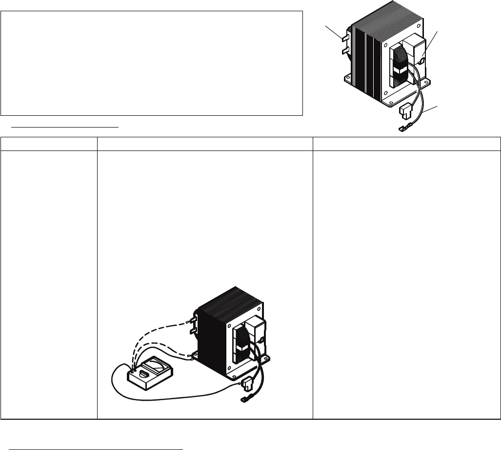
COMPONENT
HIGH-VOLTAGE
TRANSFORMER
1) Measure the resistance:
With an ohm-meter on R x1 scale.
a. Primary winding;
b. Filament winding;
c. Secondary winding;
2) Measure the resistance:
with an ohm-meter on highest scale.
a. Primary winding to ground;
b. Filament winding to ground;
CHECKOUT PROCEDURE RESULT
Normal reading:
Approximately 1.0 ohms
Less than 1 ohm.
Approximately 83 ohms
Normal reading:
Infinite ohms.
Infinite ohms.
Note: Remove varnish of measured point.
PRIMARY
WINDINGS
Secondary
Windings
Filament
Windings
Figure 2
Figure 3
A. TEST PROCEDURES
F. CHANGING POWER SUPPLY CORD
(See exploded view on page 5)
(1) Unfasten 1 screw for ground and pull out the
2 wires of the power cord from the terminal plate.
(2) Remove 1 screw for the bottom bracket of the
cord bushing.
(3) Install the new power supply cord with the
reverse procedure of above (1) to (2).
WARNING:
For changing the power supply cord, never use
other than the following.
Key No. Order No. Parts Name
5 617 140 1561 Power cord Ass’y
6 617 140 1332 Cord bush
7 617 140 1349 Bottom bracket
5. DISASSEMBY INSTRUCTIONS
- 4 -
Maintenance:
The microwave ovens are designed, manufactured, and tested for years of dependable operation. However, the
oven may require service from time to time if the consumable components listed below are not replaced at the
appropriate time. For protection from unexpected service calls and undue inconvenience, we recommend that
the user has the listed parts replaced at the intervals below, (at customer cost).
This will avoid the trouble of repeated service calls after the expiration of the warranty period.
Consumable components:
When more than 1,250 hours of accumulative cooking time or more than 200,000 cycles of door opening/closing
is observed by key operations, the following consumable components will be replaced.
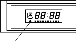
(Maintenance light in window display indicates when accumulative cooking time reaches 1,250 hours.)
Light
1. Magnetron Tube, Part No. 415 002 7702
2. Printed Circuit Board-Relay, Part No. 617 137 3844
3. Switch base Assembly, Part No. 617 205 1208
4. Door Latch, part No. 617 068 1087
When more than 2,000 hours of accumulative cooking time is observed, the following consumable compo-
nents should be replaced.
5. Blower motor, Part No. 617 140 1585
When slow rotating of blower motor is observed after removing dust from blower motor, blower motor must
be replaced.
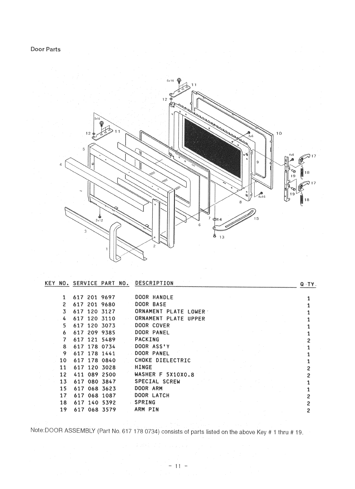
6. Door hinge, Part No. 617 120 3028
When a worn door hinge is observed and proper door adjustments can not be made, the door hinge must
be replaced.
7. Door Assembly, Part No. 617 178 0734
When a worn door pin is observed and proper door adjustments can not be made, the door assembly must
be replaced.
- 5 -
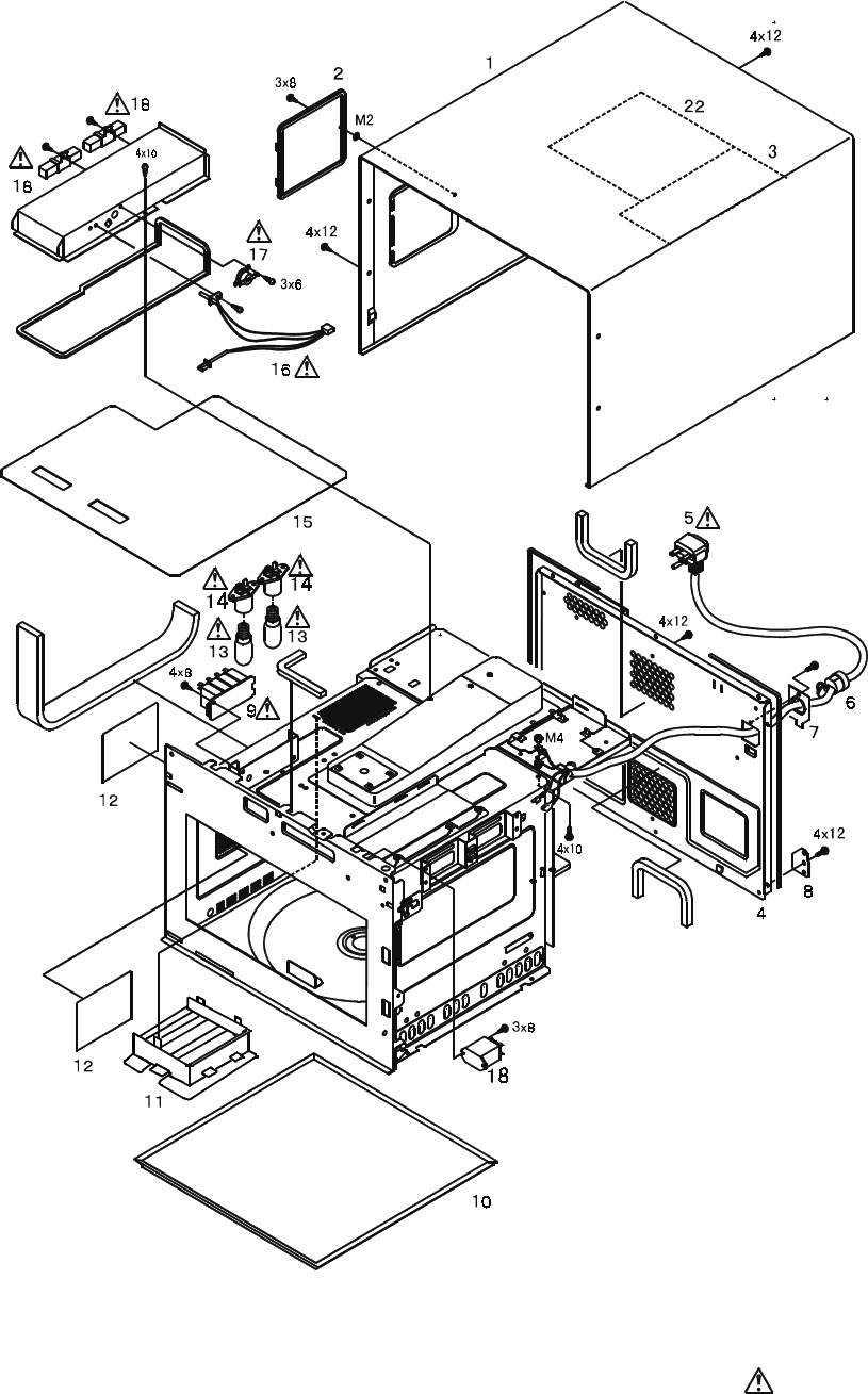
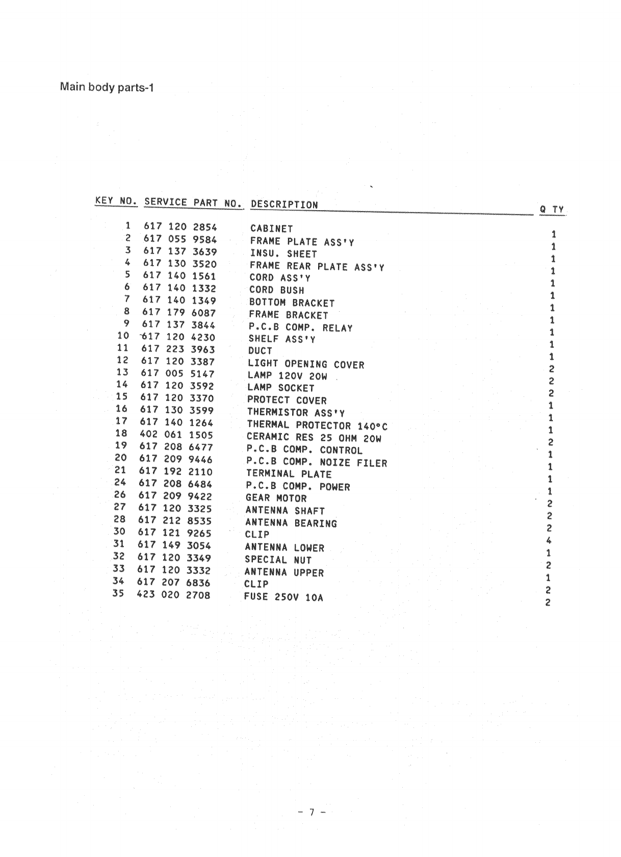
6. EXPLODED VIEW AND PARTS LIST
Main body Parts-1
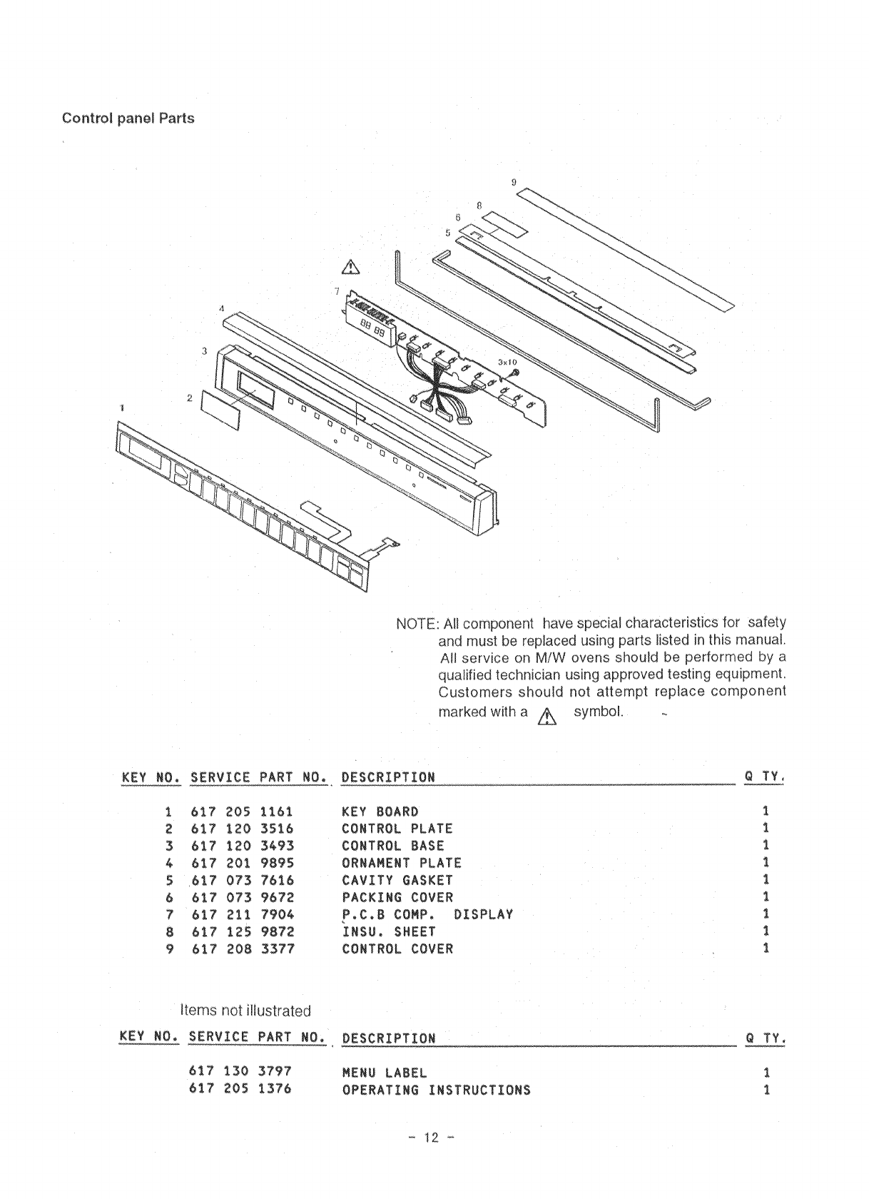
NOTE: All component have special characteristics for safety and must be replaced using parts listed in
this manual.
All service on M/W ovens should be performed by a qualified technician using approved testing
equipment. Customers should not attempt replace component marked with a symbol.
- 6 -
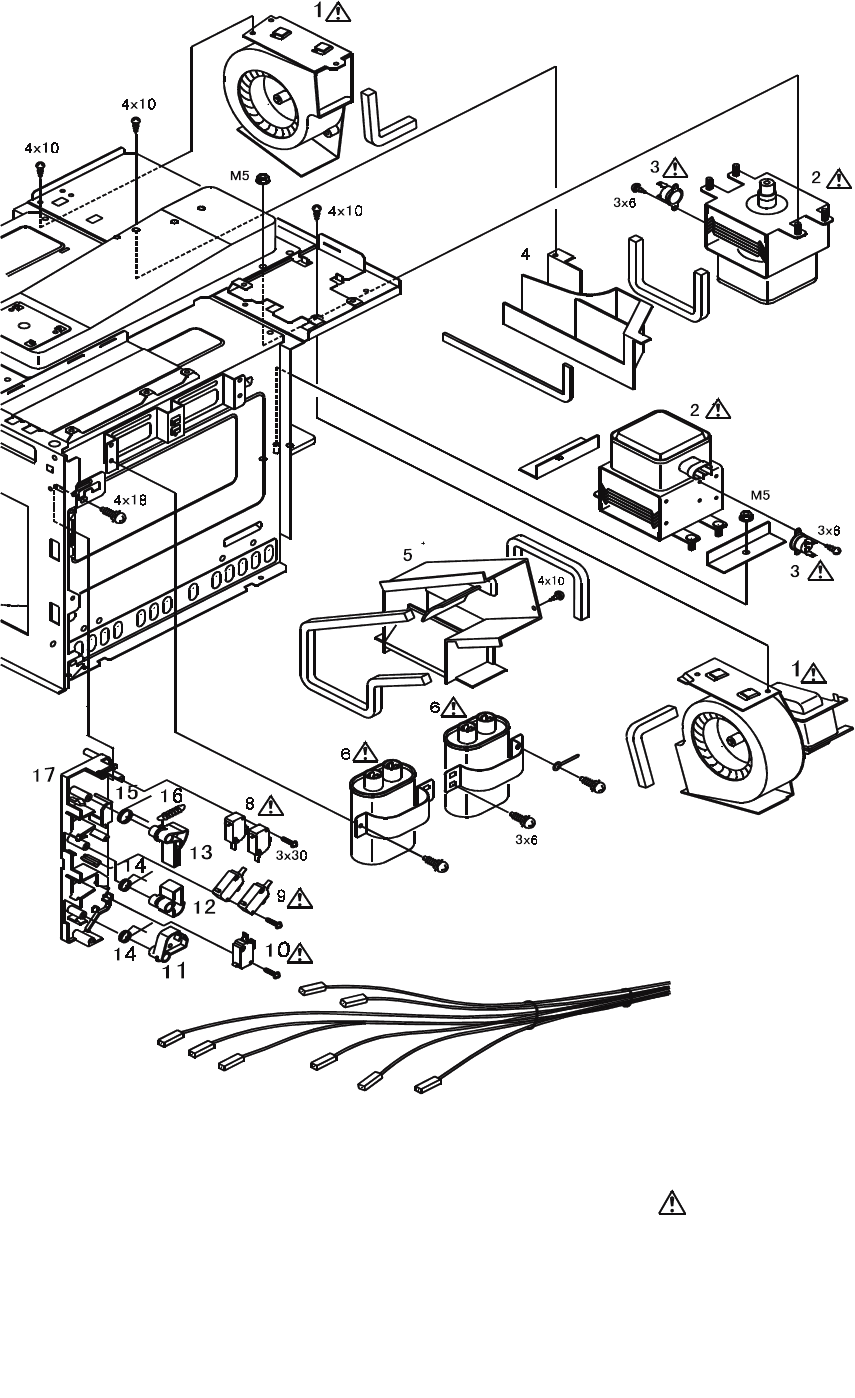
NOTE: All component have special characteristics for safety and must be replaced using parts listed
in this manual.
All service on M/W ovens should be performed by a qualified technician using approved testing
equipment. Customers should not attempt replace component marked with a symbol.
- 8 -
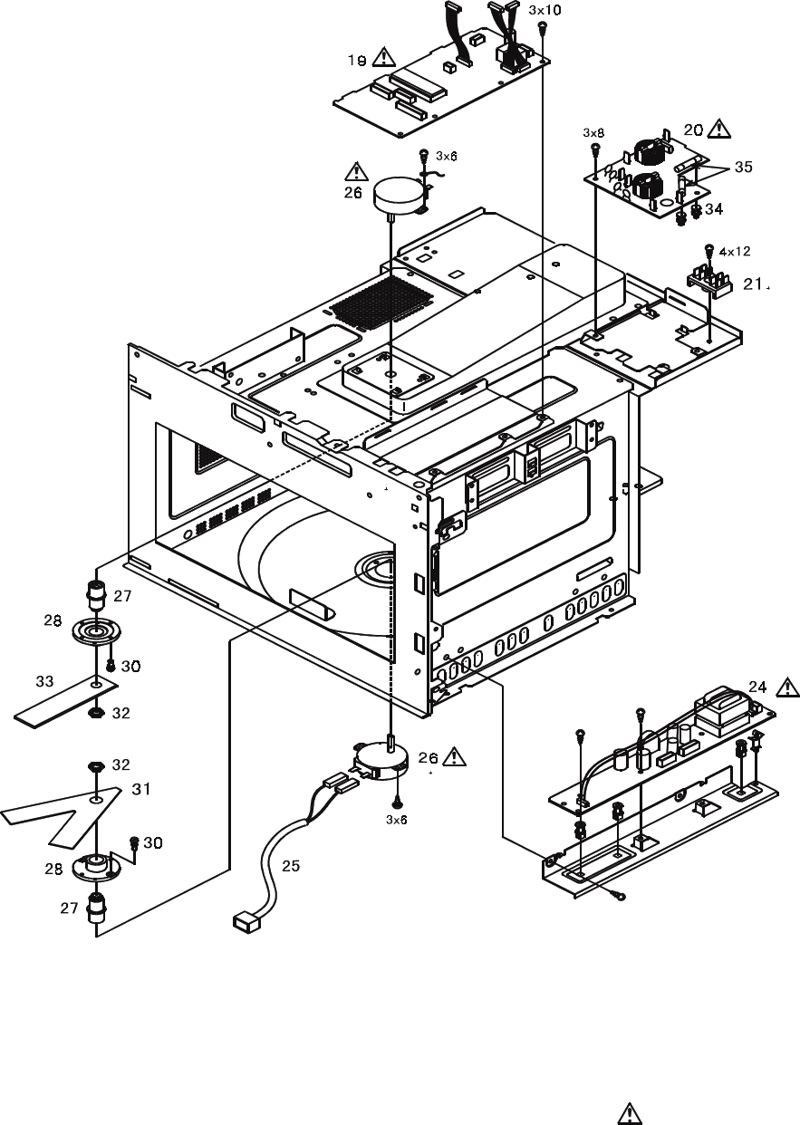
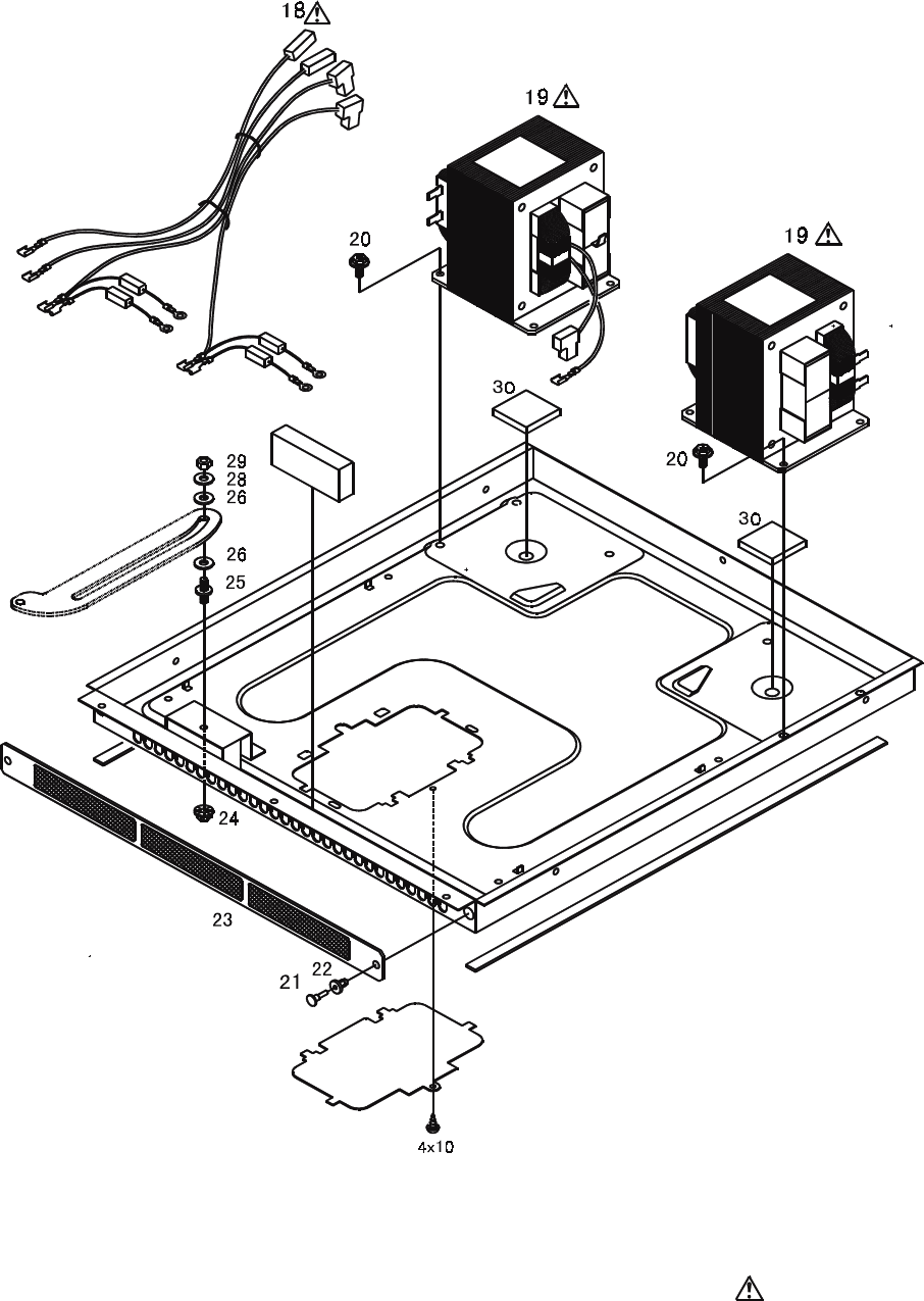
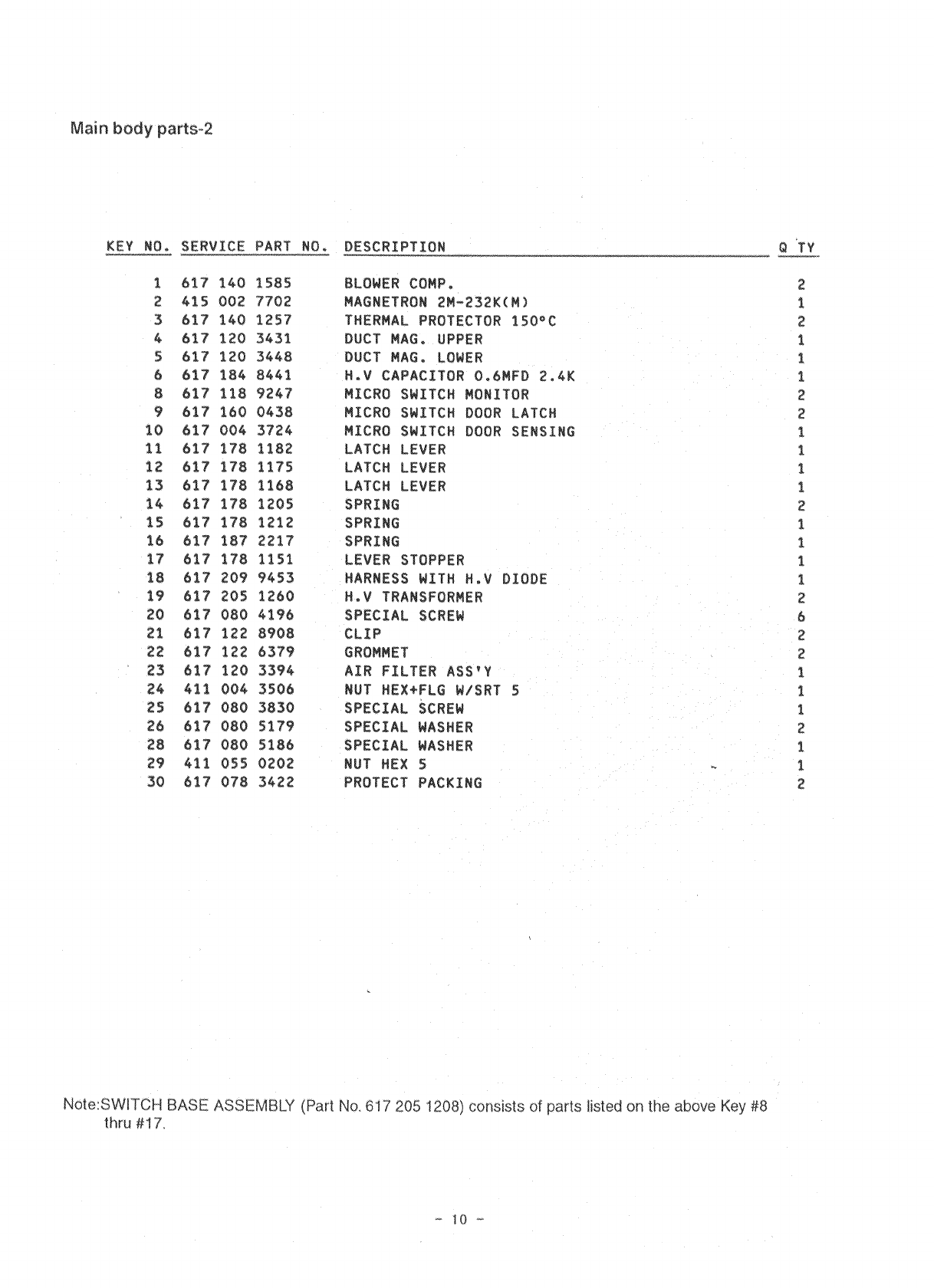
Main body Parts-2
NOTE: All component have special characteristics for safety and must be replaced using parts listed
in this manual.
All service on M/W ovens should be performed by a qualified technician using approved testing
equipment. Customers should not attempt replace component marked with a symbol.
- 9 -
NOTE: All component have special characteristics for safety and must be replaced using parts listed
in this manual.
All service on M/W ovens should be performed by a qualified technician using approved testing
equipment. Customers should not attempt replace component marked with a symbol.
- 16 -
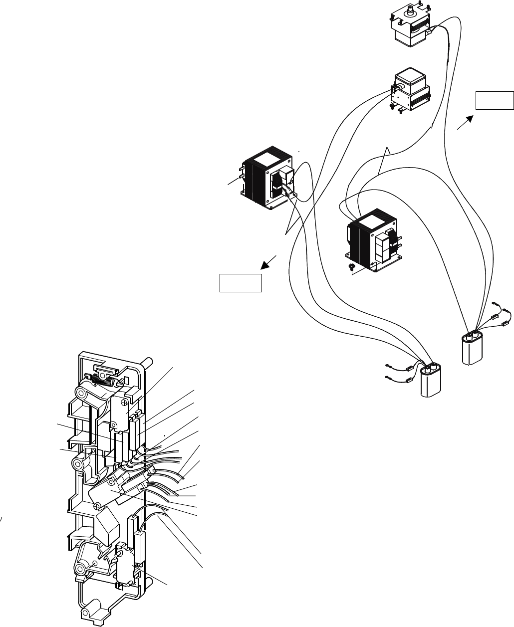
Wiring of High voltage Circuit
Door sensing switch
Viewed from back
Brown(C Inside)
Orange(C)
Brown
White/
Wiring of Switches
Purple
Purple
Monitor switch
Blue(NC Inside)
Light
Blue
Interlock switch
Orange
White
Pink(NO Insde)
Red wire
Transformer
Transformer
Red wire
Red wire
Red wire
Filament Winding
Filament Winding
Lower
Magnetron
Magnetron
Upper
Upper
Capacitor
Capacitor
Lower
Lower
Upper
Pink/Light Blue
Black
Brown
Blue/Blue
(NO)
(NC)
Yellow
Black
FRONTFRONT
FRONTFRONT
FRONT
BACKBACK
BACKBACK
BACK