Sanyo C0971 Users Manual SM655_05_I_KS0971_BA
CL1271 to the manual ba7b9fbb-fb28-4166-b33c-1e49deac1ecc
2015-01-26
: Sanyo Sanyo-C0971-Users-Manual-336368 sanyo-c0971-users-manual-336368 sanyo pdf
Open the PDF directly: View PDF ![]() .
.
Page Count: 108 [warning: Documents this large are best viewed by clicking the View PDF Link!]
IMPORTANT
These air conditioners employ new
refrigerant R410A.
Pay special attention when
servicing the unit.
TECHNICAL & SERVICE MANUAL
KS0971+C0971
+CL0971
KS1271+C1271
+CL1271
DC INVERTER SPLIT SYSTEM AIR CONDITIONER
Indoor Unit
Destination: North America
Outdoor Model No.
C0971
C1271
CL0971
CL1271
Product Code No.
1 852 330 23
1 852 330 24
1 852 330 25
1 852 330 26
Outdoor Unit
KS0971
KS1271
C0971
C1271
CL0971
CL1271
REFERENCE NO. SM700655-05
Indoor Model No.
KS0971
KS1271
Product Code No.
1 852 099 81
1 852 099 82
FILE NO.
When Wiring
ELECTRICAL SHOCK CAN CAUSE
SEVERE PERSONAL INJURY OR DEATH.
ONLY A QUALIFIED, EXPERIENCED
ELECTRICIAN SHOULD ATTEMPT TO
WIRE THIS SYSTEM.
SPECIAL PRECAUTIONS
This symbol refers to a hazard or
unsafe practice which can result
in severe personal injury or death.
This symbol refers to a hazard
or unsafe practice which can
result in personal injury or
product or property damage.
CAUTION
CAUTION
WARNING
WARNING
Important!
Please Read Before Starting
This air conditioning system meets strict safety and operating
standards. As the installer or service person, it is an
important part of your job to install or service the system so it
operates safely and efficiently.
For safe installation and trouble-free operation, you must:
Carefully read this instruction booklet before beginning.
Follow each installation or repair step exactly as shown.
Observe all local, state, and national electrical codes.
Pay close attention to all warning and caution notices given
in this manual.
If Necessary, Get Help
These instructions are all you need for most installation
sites and maintenance conditions. If you require help for
a special problem, contact our sales/service outlet or
your certified dealer for additional instructions.
In Case of Improper Installation
The manufacturer shall in no way be responsible for
improper installation or maintenance service, including
failure to follow the instructions in this document.
Do not supply power to the unit until all wiring and tubing
are completed or reconnected and checked.
Highly dangerous electrical voltages are used in this
system. Carefully refer to the wiring diagram and these
instructions when wiring. Improper connections and
inadequate grounding can cause accidental injury or death.
Ground the unit following local electrical codes.
Connect all wiring tightly. Loose wiring may cause
overheating at connection points and a possible fire
hazard.
When Transporting
Be careful when picking up and moving the indoor and
outdoor units. Get a partner to help, and bend your knees
when lifting to reduce strain on your back. Sharp edges or thin
aluminum fins on the air conditioner can cut your fingers.
When Installing
In a Ceiling or Wall
Make sure the ceiling/wall is strong enough to hold the unit’s
weight. It may be necessary to construct a strong wood or
metal frame to provide added support.
In a Room
Properly insulate any tubing run inside a room to prevent
"sweating" that can cause dripping and water damage to walls
and floors.
In Moist or Uneven Locations
Use a raised concrete pad or concrete blocks to provide a
solid, level foundation for the outdoor unit. This prevents
water damage and abnormal vibration.
In an Area with High Winds
Securely anchor the outdoor unit down with bolts and a metal
frame. Provide a suitable air baffle.
In a Snowy Area (for Heat Pump-type Systems)
Install the outdoor unit on a raised platform that is higher than
drifting snow. Provide snow vents.
When Connecting Refrigerant Tubing
Use the flare method for connecting tubing.
Apply refrigerant lubricant to the matching surfaces of the
flare and union tubes before connecting them, then tighten
the nut with a torque wrench for a leak-free connection.
Check carefully for leaks before starting the test run.
When Servicing
Turn the power off at the main power box (mains) before
opening the unit to check or repair electrical parts and
wiring.
Keep your fingers and clothing away from any moving parts.
Clean up the site after you finish, remembering to check
that no metal scraps or bits of wiring have been left inside
the unit being serviced.
Others
Ventilate any enclosed areas when installing or testing the
refrigeration system. Escaped refrigerant gas, on contact
with fire or heat, can produce dangerously toxic gas.
Confirm upon completing installation that no refrigerant gas
is leaking. If escaped gas comes in contact with a stove,
gas water heater, electric room heater or other heat source,
it can produce dangerously toxic gas.
•
•
•
•
•
•
•
•
•
•
•
•
2
Table of Contents
1. OPERATING RANGE
2. SPECIFICATIONS
2-1.Unit Specifications
2-2.Major Component Specifications
2-3.Other Component Specifications
3. DIMENSIONAL DATA
4. REFRIGERANT FLOW DIAGRAM
4-1.Refrigerant Flow Diagram
5. PERFORMANCE DATA
5-1.Temperature Charts
5-2.Cooling Capacity
5-3.Cooling Capacity (Low Ambient)
5-4.Air Throw Distance Charts
6. ELECTRICAL DATA
6-1. Electrical Characteristics
6-2. Electric Wiring Diagrams
7. MAINTENANCE
7-1.Address Setting of the Remote Control Unit
7-2.Disconnecting and Connecting Positive Connector for Outdoor Unit
8. FUNCTIONS
8-1.Operation Functions
8-2.Protective Functions
9. TROUBLESHOOTING
9-1.Precautions before Performing Inspection or Repair
9-2.Method of Self-Diagnostics
9-3.Checking the Indoor and Outdoor Units
9-4.Trouble Diagnosis of Fan Motor
9-5.Noise Malfunction and Electromagnetic Interference
5
6
10
16
17
19
20
24
26
28
30
32
35
36
37
39
40
40
42
46
47
...................................................................................................................
.............................................................................................................
.......................................................................................
.......................................................................................
.....................................................................................................................
...................................................................................................
............................................................................................................
.................................................................................................................
........................................................................................
.................................................................................................
....................................................................................................
....................................................................................................
.......................................................................
..................................
...........................................................................................................
...........................................................................................................
...........................................................
.................................................................................................
..............................................................................
..........................................................................................
..........................................................
Page
3

10. CHECKING ELECTRICAL COMPONENTS
10-1.Measurement of Insulation Resistance
10-2.Checking Continuity of Fuse on PCB Ass'y
11. REFRIGERANT R410A:
SPECIAL PRECAUTIONS WHEN SERVICING UNIT
11-1.Characteristics of New Refrigerant R410A
11-2.Checklist before Servicing
11-3.Tools Specifically for R410A
11-4.Tubing Installation Procedures
11-5.In Case of Compressor Malfunction
11-6.In Case Refrigerant is Leaking
11-7.Charging Additional Refrigerant
11-8.Retro-Fitting Existing Systems
APPENDIX A INSTRUCTION MANUAL
APPENDIX B INSTALLATION INSTRUCTIONS
48
49
50
51
52
52
53
55
56
56
A-1
A-2
...............................................................................
.........................................................................
.........................................................................
...................................................................................................
................................................................................................
............................................................................................
....................................................................................
............................................................................................
..........................................................................................
............................................................................................
..........................................................................................
.............................................................................
Page
4

95 °F D.B. / 71 °F W.B.
67 °F D.B. / 57 °F W.B.
1. OPERATING RANGE
Maximum
Minimum
115 °F D.B.
67 °F D.B.
Temperature Indoor Air Intake Temp. Outdoor Air Intake Temp.
Cooling
95 °F D.B. / 71 °F W.B.
67 °F D.B. / 57 °F W.B.
Maximum
Minimum
115 °F D.B.
0 °F D.B.
Temperature Indoor Air Intake Temp. Outdoor Air Intake Temp.
Cooling
Models:KS0971 + C0971
KS1271 + C1271
Models:KS0971 + CL0971
KS1271 + CL1271
5

2. SPECIFICATIONS
2-1. Unit Specifications
Indoor Unit KS0971
Outdoor Unit C0971
Remarks: Rating conditions are:
Cooling: Indoor air temperature 80°F D.B. / 67°F W.B.
Outdoor air temperature 95°F D.B. / 75°F W.B.
DATA SUBJECT TO CHANGE WITHOUT NOTICE.
Vertical
dB-A
dB-A
Indoor : Hi/Me/Lo/Qt*
Outdoor : Hi
Air Filter
Compressor
Refrigerant / Amount charged at shipment Ibs (g)
Refrigerant Control
7.6
750
( 2.5 to 7.6 )
( 250 to 750 )
9,000
2.65
( 3,000 to 9,000 )
( 0.9 to 2.65 )
Shipping Volume
Cooling
7,650
1,350
Net
Shipping
Package Dimensions
Weight
Height × Width × Depth
Height × Width × Depth
Ibs (kg)
Ibs (kg)
cu.ft (m3)
(mm)
inch
(mm)
115V Single-Phase 60Hz
inch
104 to 126
Dimensions & Weight
(*Qt = Quiet mode)
Refrigerant Tubing Connections
Unit Dimensions
Operation Sound
Electrical Rating
Sensible Capacity
Latent Capacity
WPower Input
V
A
Available Voltage Range
Running Amperes
Refrigerant Tube Kit / Accessories
Narrow tube
Wide tube
Refrigerant inch (mm)
Tube Diameter inch (mm)
19.8
24.3
2.82
(9.0)
(11.0)
(0.08)
72.8
79.4
6.35
(33.0)
(36.0)
(0.18)
23-5/8 × 33-11/16 × 14-1/4
(600 × 856 × 362)
(285 × 825 × 189) (548 × 720 × 265)
10-1/32 × 35-7/16 × 13-25/32
(255 × 900 × 350)
Outdoor UnitIndoor Unit
11-7/32 × 32-15/32 × 7-7/16 21-9/16 × 28-11/32 × 10-7/16
1/4 (6.35)
3/8 (9.52)
ft (m)Max. allowable tubing length at shipment
Flare Type
25 (7.5)
34 / 31 / 28 / 23
46
R410A / 2.09 (950)
Electric Expansion Valve
Washable, Anti-Mold
DC Rotary (Inverter)
Manual
Auto
Timer
Indoor / OutdoorFan Speeds
24-Hour ON or OFF Timer, 1-Hour OFF Timer
Auto and 3 steps / Auto (Hi, Me, Lo)
Airflow Direction (Indoor) Horizontal
Controls / Temperature Control
Control Unit
Microprocessor / I.C. Thermister
Wireless Remote Control Unit
Features
Compressor Locked Rotor Amperes
Optional / Air Clean Filter
BTU/h
Performance
%Power Factor 86
A20
Voltage Rating
BTU/h
kW
Total Capacity
BTU/h
SEER BTU/Wh 16
282 (480)Air Circulation (High) ft3/min (m3/h)
3.4Moisture Removal (High) Pints/h
EER BTU/h/W 12
Fuse or Circuit Breaker Capacity A20
6

Indoor Unit KS1271
Outdoor Unit C1271
DATA SUBJECT TO CHANGE WITHOUT NOTICE.
Vertical
dB-A
dB-A
Indoor : Hi/Me/Lo/Qt*
Outdoor : Hi
Air Filter
Compressor
Refrigerant / Amount charged at shipment Ibs (g)
Refrigerant Control
10.9
1,090
( 2.5 to 10.9 )
( 250 to 1,090 )
11,900
3.5
( 3,000 to 11,900 )
( 0.9 to 3.5 )
Shipping Volume
Cooling
9,100
2,800
Net
Shipping
Package Dimensions
Weight
Height × Width × Depth
Height × Width × Depth
Ibs (kg)
Ibs (kg)
cu.ft (m3)
(mm)
inch
(mm)
115V Single-Phase 60Hz
inch
104 to 126
Dimensions & Weight
(*Qt = Quiet mode)
Refrigerant Tubing Connections
Unit Dimensions
Operation Sound
Electrical Rating
Sensible Capacity
Latent Capacity
WPower Input
V
A
Available Voltage Range
Running Amperes
Refrigerant Tube Kit / Accessories
Narrow tube
Wide tube
Refrigerant inch (mm)
Tube Diameter inch (mm)
19.8
24.3
2.82
(9.0)
(11.0)
(0.08)
75.0
81.6
6.35
(34.0)
(37.0)
(0.18)
23-5/8 × 33-11/16 × 14-1/4
(600 × 856 × 362)
(285 × 825 × 189) (548 × 720 × 265)
10-1/32 × 35-7/16 × 13-25/32
(255 × 900 × 350)
Outdoor UnitIndoor Unit
11-7/32 × 32-15/32 × 7-7/16 21-9/16 × 28-11/32 × 10-7/16
1/4 (6.35)
3/8 (9.52)
ft (m)Max. allowable tubing length at shipment
Flare Type
25 (7.5)
36 / 33 / 29 / 25
47
R410A / 2.43 (1,100)
Electric Expansion Valve
Washable, Anti-Mold
DC Rotary (Inverter)
Manual
Auto
Timer
Indoor / OutdoorFan Speeds
24-Hour ON or OFF Timer, 1-Hour OFF Timer
Auto and 3 steps / Auto (Hi, Me, Lo)
Airflow Direction (Indoor) Horizontal
Controls / Temperature Control
Control Unit
Microprocessor / I.C. Thermister
Wireless Remote Control Unit
Features
Compressor Locked Rotor Amperes
Optional / Air Clean Filter
BTU/h
Performance
%Power Factor 87
A20
Voltage Rating
BTU/h
kW
Total Capacity
BTU/h
SEER BTU/Wh 17
294 (500)Air Circulation (High) ft3/min (m3/h)
4.26Moisture Removal (High) Pints/h
EER BTU/h/W 10.9
Fuse or Circuit Breaker Capacity A20
Remarks: Rating conditions are:
Cooling: Indoor air temperature 80°F D.B. / 67°F W.B.
Outdoor air temperature 95°F D.B. / 75°F W.B.
7

Indoor Unit KS0971
Outdoor Unit CL0971
Remarks: Rating conditions are:
Cooling: Indoor air temperature 80°F D.B. / 67°F W.B.
Outdoor air temperature 95°F D.B. / 75°F W.B.
DATA SUBJECT TO CHANGE WITHOUT NOTICE.
Vertical
dB-A
dB-A
Indoor : Hi/Me/Lo/Qt*
Outdoor : Hi
Air Filter
Compressor
Refrigerant / Amount charged at shipment Ibs (g)
Refrigerant Control
7.6
750
( 2.5 to 7.6 )
( 250 to 750 )
9,000
2.65
( 3,000 to 9,000 )
( 0.9 to 2.65 )
Shipping Volume
Cooling
7,650
1,350
Net
Shipping
Package Dimensions
Weight
Height × Width × Depth
Height × Width × Depth
Ibs (kg)
Ibs (kg)
cu.ft (m3)
(mm)
inch
(mm)
115V Single-Phase 60Hz
inch
104 to 126
Dimensions & Weight
(*Qt = Quiet mode)
Refrigerant Tubing Connections
Unit Dimensions
Operation Sound
Electrical Rating
Sensible Capacity
Latent Capacity
WPower Input
V
A
Available Voltage Range
Running Amperes
Refrigerant Tube Kit / Accessories
Narrow tube
Wide tube
Refrigerant inch (mm)
Tube Diameter inch (mm)
19.8
24.3
2.82
(9.0)
(11.0)
(0.08)
72.8
79.4
6.35
(33.0)
(36.0)
(0.18)
23-5/8 × 33-11/16 × 14-1/4
(600 × 856 × 362)
(285 × 825 × 189) (548 × 720 × 265)
10-1/32 × 35-7/16 × 13-25/32
(255 × 900 × 350)
Outdoor UnitIndoor Unit
11-7/32 × 32-15/32 × 7-7/16 21-9/16 × 28-11/32 × 10-7/16
1/4 (6.35)
3/8 (9.52)
ft (m)Max. allowable tubing length at shipment
Flare Type
25 (7.5)
34 / 31 / 28 / 23
46
R410A / 2.09 (950)
Electric Expansion Valve
Washable, Anti-Mold
DC Rotary (Inverter)
Manual
Auto
Timer
Indoor / OutdoorFan Speeds
24-Hour ON or OFF Timer, 1-Hour OFF Timer
Auto and 3 steps / Auto (Hi, Me, Lo)
Airflow Direction (Indoor) Horizontal
Controls / Temperature Control
Control Unit
Microprocessor / I.C. Thermister
Wireless Remote Control Unit
Features
Compressor Locked Rotor Amperes
Optional / Air Clean Filter
BTU/h
Performance
%Power Factor 86
A20
Voltage Rating
BTU/h
kW
Total Capacity
BTU/h
SEER BTU/Wh 16
282 (480)Air Circulation (High) ft3/min (m3/h)
3.4Moisture Removal (High) Pints/h
EER BTU/h/W 12
Fuse or Circuit Breaker Capacity A20
8

Indoor Unit KS1271
Outdoor Unit CL1271
DATA SUBJECT TO CHANGE WITHOUT NOTICE.
Vertical
dB-A
dB-A
Indoor : Hi/Me/Lo/Qt*
Outdoor : Hi
Air Filter
Compressor
Refrigerant / Amount charged at shipment Ibs (g)
Refrigerant Control
10.9
1,090
( 2.5 to 10.9 )
( 250 to 1,090 )
11,900
3.5
( 3,000 to 11,900 )
( 0.9 to 3.5 )
Shipping Volume
Cooling
9,100
2,800
Net
Shipping
Package Dimensions
Weight
Height × Width × Depth
Height × Width × Depth
Ibs (kg)
Ibs (kg)
cu.ft (m3)
(mm)
inch
(mm)
115V Single-Phase 60Hz
inch
104 to 126
Dimensions & Weight
(*Qt = Quiet mode)
Refrigerant Tubing Connections
Unit Dimensions
Operation Sound
Electrical Rating
Sensible Capacity
Latent Capacity
WPower Input
V
A
Available Voltage Range
Running Amperes
Refrigerant Tube Kit / Accessories
Narrow tube
Wide tube
Refrigerant inch (mm)
Tube Diameter inch (mm)
19.8
24.3
2.82
(9.0)
(11.0)
(0.08)
75.0
81.6
6.35
(34.0)
(37.0)
(0.18)
23-5/8 × 33-11/16 × 14-1/4
(600 × 856 × 362)
(285 × 825 × 189) (548 × 720 × 265)
10-1/32 × 35-7/16 × 13-25/32
(255 × 900 × 350)
Outdoor UnitIndoor Unit
11-7/32 × 32-15/32 × 7-7/16 21-9/16 × 28-11/32 × 10-7/16
1/4 (6.35)
3/8 (9.52)
ft (m)Max. allowable tubing length at shipment
Flare Type
25 (7.5)
36 / 33 / 29 / 25
47
R410A / 2.43 (1,100)
Electric Expansion Valve
Washable, Anti-Mold
DC Rotary (Inverter)
Manual
Auto
Timer
Indoor / OutdoorFan Speeds
24-Hour ON or OFF Timer, 1-Hour OFF Timer
Auto and 3 steps / Auto (Hi, Me, Lo)
Airflow Direction (Indoor) Horizontal
Controls / Temperature Control
Control Unit
Microprocessor / I.C. Thermister
Wireless Remote Control Unit
Features
Compressor Locked Rotor Amperes
Optional / Air Clean Filter
BTU/h
Performance
%Power Factor 87
A20
Voltage Rating
BTU/h
kW
Total Capacity
BTU/h
SEER BTU/Wh 17
294 (500)Air Circulation (High) ft3/min (m3/h)
4.26Moisture Removal (High) Pints/h
EER BTU/h/W 10.9
Fuse or Circuit Breaker Capacity A20
Remarks: Rating conditions are:
Cooling: Indoor air temperature 80°F D.B. / 67°F W.B.
Outdoor air temperature 95°F D.B. / 75°F W.B.
9

Indoor Unit KS0971
MP24Z3
Flap Motor
Type Stepping Motor
Rating
Model
Coil Resistance Ohm
(Ambient Temp. 77 °F (25 °C))
Each Pair of Terminal : 400 +/- 7%
DC 12V
Aluminum Plate Fin / Copper Tube
2
19.5
2.02 (0.188) Face Area
Coil
Rows
Fins per inch
Heat Exchanger Coil
ft2 (m2)
DATA SUBJECT TO CHANGE WITHOUT NOTICE.
-
Control PCB
Control Circuit Fuse
Controls
Part No.
Microprocessor
250V 3A
CB-KS0971
1 ... D3-11/16 / L24-31/32 (D94/L634)
RCS-4VPIS4U
Cross-Flow
AC Motor
IBH-884-076 ... 1
4
BRN-WHT : 57.9
RED-WHT : 55.2
16
1,200
Thermal Fuse
266 (130)
4.5
250
Fan
Remote Control Unit
Q'ty ... Dia. and Length
Type
inch (mm)
Fan Motor
Nominal Output
Coil Resistance
Rough Measure RPM (Cool)
Type
Model ... Q'ty
No. of Poles
Safety Device
Type
Operating Temp.
Close °F (°C)
Open °F (°C)
(Ambient Temp. 68 °F (20 °C))
Run Capacitor Micro F
VAC
W
Ohm
2-2. Major Component Specifications
2-2-1. Indoor Unit
10

Indoor Unit KS1271
MP24Z3
Flap Motor
Type Stepping Motor
Rating
Model
Coil Resistance Ohm
(Ambient Temp. 77 °F (25 °C))
Each Pair of Terminal : 400 +/- 7%
DC 12V
Aluminum Plate Fin / Copper Tube
2
19.5
2.02 (0.188) Face Area
Coil
Rows
Fins per inch
Heat Exchanger Coil
ft2 (m2)
DATA SUBJECT TO CHANGE WITHOUT NOTICE.
-
Control PCB
Control Circuit Fuse
Controls
Part No.
Microprocessor
250V 3A
CB-KS1271
1 ... D3-11/16 / L24-31/32 (D94/L634)
RCS-4VPIS4U
Cross-Flow
AC Motor
IBH-884-076 ... 1
4
BRN-WHT : 57.9
RED-WHT : 55.2
16
1,250
Thermal Fuse
266 (130)
4.5
250
Fan
Remote Control Unit
Q'ty ... Dia. and Length
Type
inch (mm)
Fan Motor
Nominal Output
Coil Resistance
Rough Measure RPM (Cool)
Type
Model ... Q'ty
No. of Poles
Safety Device
Type
Operating Temp.
Close °F (°C)
Open °F (°C)
(Ambient Temp. 68 °F (20 °C))
Run Capacitor Micro F
VAC
W
Ohm
11

Outdoor Unit C0971
2-2-2. Outdoor Unit
Control PCB
Control Circuit Fuse
Controls
Part No.
Microprocessor
125V 25A
CB-C0971
DATA SUBJECT TO CHANGE WITHOUT NOTICE.
Pints (cc)
WHT - BLU :
BLU - RED :
RED - WHT :
77.5
77.5
77.5
Micro F
VAC
External Finish Acrylic baked-on enamel finish
FV50S ... 0.68 (320)
-
-
Internal Controller
Yes
Aluminum Plate Fin / Copper Tube
2
18.1
Face Area ft2 (m2)3.10 (0.288)
Coil
Rows
Fins per inch
Heat Exchanger Coil
DAJ12-55J71-CU ... 1
Compressor Oil ... Amount
8
50
750
Ohm
DC Motor
Type
Compressor Model / Nominal Output
Compressor
Coil Resistance (Ambient Temp. 68 °F (20 °C)) Ohm
DC Rotary (Hermetic)
G4C090LU1ER / 900W
U - V :
V - W :
W - U :
0.81
0.81
0.81
CT (Peak current cut-off control)
Compressor Discharge Temp. Control
Operation cut-off control in abnormal ambient Temp.
Safety Device
Micro F
VAC
Run Capacitor
Crankcase Heater
Yes
Yes
Yes
Overload Relay CS-7L115
Model
Operation Temp. Open : 239 °F (115 °C), Close : 203 °F (95 °C)
-
-
-
1 ... D15-3/4 (D400)
Fan
Propeller
Q'ty ... Dia. inch (mm)
Type
Type
Over- Current Protection
(Ambient Temp. 68 °F (20 °C))
Fan Motor
Nominal Output
Coil Resistance
Safety Device
Rough Measure RPM (Cool)
Run Capacitor
Type
Model ... Q'ty
No. of Poles
W
12

Outdoor Unit C1271
Control PCB
Control Circuit Fuse
Controls
Part No.
Microprocessor
125V 25A
CB-C1271
DATA SUBJECT TO CHANGE WITHOUT NOTICE.
Pints (cc)
WHT - BLU :
BLU - RED :
RED - WHT :
77.5
77.5
77.5
Micro F
VAC
External Finish Acrylic baked-on enamel finish
FV50S ... 0.68 (320)
-
-
Internal Controller
Yes
Aluminum Plate Fin / Copper Tube
2
18.1
Face Area ft2 (m2)3.95 (0.367)
Coil
Rows
Fins per inch
Heat Exchanger Coil
DAJ12-55J71-CU ... 1
Compressor Oil ... Amount
8
50
750
Ohm
DC Motor
Type
Compressor Model / Nominal Output
Compressor
Coil Resistance (Ambient Temp. 68 °F (20 °C)) Ohm
DC Rotary (Hermetic)
G4C090LU1ER / 900W
U - V :
V - W :
W - U :
0.81
0.81
0.81
CT (Peak current cut-off control)
Compressor Discharge Temp. Control
Operation cut-off control in abnormal ambient Temp.
Safety Device
Micro F
VAC
Run Capacitor
Crankcase Heater
Yes
Yes
Yes
Overload Relay CS-7L115
Model
Operation Temp. Open : 239 °F (115 °C), Close : 203 °F (95 °C)
-
-
-
1 ... D15-3/4 (D400)
Fan
Propeller
Q'ty ... Dia. inch (mm)
Type
Type
Over- Current Protection
(Ambient Temp. 68 °F (20 °C))
Fan Motor
Nominal Output
Coil Resistance
Safety Device
Rough Measure RPM (Cool)
Run Capacitor
Type
Model ... Q'ty
No. of Poles
W
13

Outdoor Unit CL0971
Control PCB
Control Circuit Fuse
Controls
Part No.
Microprocessor
125V 25A
CB-CL0971
DATA SUBJECT TO CHANGE WITHOUT NOTICE.
Pints (cc)
WHT - BLU :
BLU - RED :
RED - WHT :
77.5
77.5
77.5
Micro F
VAC
External Finish Acrylic baked-on enamel finish
FV50S ... 0.68 (320)
-
-
Internal Controller
Yes
Aluminum Plate Fin / Copper Tube
2
18.1
Face Area ft2 (m2)3.10 (0.288)
Coil
Rows
Fins per inch
Heat Exchanger Coil
DAJ12-55J71-CU ... 1
Compressor Oil ... Amount
8
50
750
Ohm
DC Motor
Type
Compressor Model / Nominal Output
Compressor
Coil Resistance (Ambient Temp. 68 °F (20 °C)) Ohm
DC Rotary (Hermetic)
G4C090LU1ER / 900W
U - V :
V - W :
W - U :
0.81
0.81
0.81
CT (Peak current cut-off control)
Compressor Discharge Temp. Control
Operation cut-off control in abnormal ambient Temp.
Safety Device
Micro F
VAC
Run Capacitor
Crankcase Heater
Yes
Yes
Yes
Overload Relay CS-7L115
Model
Operation Temp. Open : 239 °F (115 °C), Close : 203 °F (95 °C)
-
-
115V 20W
1 ... D15-3/4 (D400)
Fan
Propeller
Q'ty ... Dia. inch (mm)
Type
Type
Over- Current Protection
(Ambient Temp. 68 °F (20 °C))
Fan Motor
Nominal Output
Coil Resistance
Safety Device
Rough Measure RPM (Cool)
Run Capacitor
Type
Model ... Q'ty
No. of Poles
W
14

Outdoor Unit CL1271
Control PCB
Control Circuit Fuse
Controls
Part No.
Microprocessor
125V 25A
CB-CL1271
DATA SUBJECT TO CHANGE WITHOUT NOTICE.
Pints (cc)
WHT - BLU :
BLU - RED :
RED - WHT :
77.5
77.5
77.5
Micro F
VAC
External Finish Acrylic baked-on enamel finish
FV50S ... 0.68 (320)
-
-
Internal Controller
Yes
Aluminum Plate Fin / Copper Tube
2
18.1
Face Area ft2 (m2)3.95 (0.367)
Coil
Rows
Fins per inch
Heat Exchanger Coil
DAJ12-55J71-CU ... 1
Compressor Oil ... Amount
8
50
750
Ohm
DC Motor
Type
Compressor Model / Nominal Output
Compressor
Coil Resistance (Ambient Temp. 68 °F (20 °C)) Ohm
DC Rotary (Hermetic)
G4C090LU1ER / 900W
U - V :
V - W :
W - U :
0.81
0.81
0.81
CT (Peak current cut-off control)
Compressor Discharge Temp. Control
Operation cut-off control in abnormal ambient Temp.
Safety Device
Micro F
VAC
Run Capacitor
Crankcase Heater
Yes
Yes
Yes
Overload Relay CS-7L115
Model
Operation Temp. Open : 239 °F (115 °C), Close : 203 °F (95 °C)
-
-
115V 20W
1 ... D15-3/4 (D400)
Fan
Propeller
Q'ty ... Dia. inch (mm)
Type
Type
Over- Current Protection
(Ambient Temp. 68 °F (20 °C))
Fan Motor
Nominal Output
Coil Resistance
Safety Device
Rough Measure RPM (Cool)
Run Capacitor
Type
Model ... Q'ty
No. of Poles
W
15
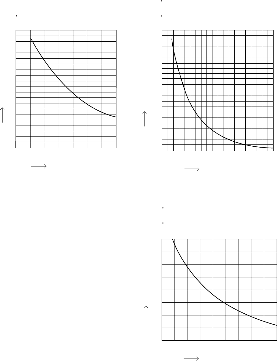
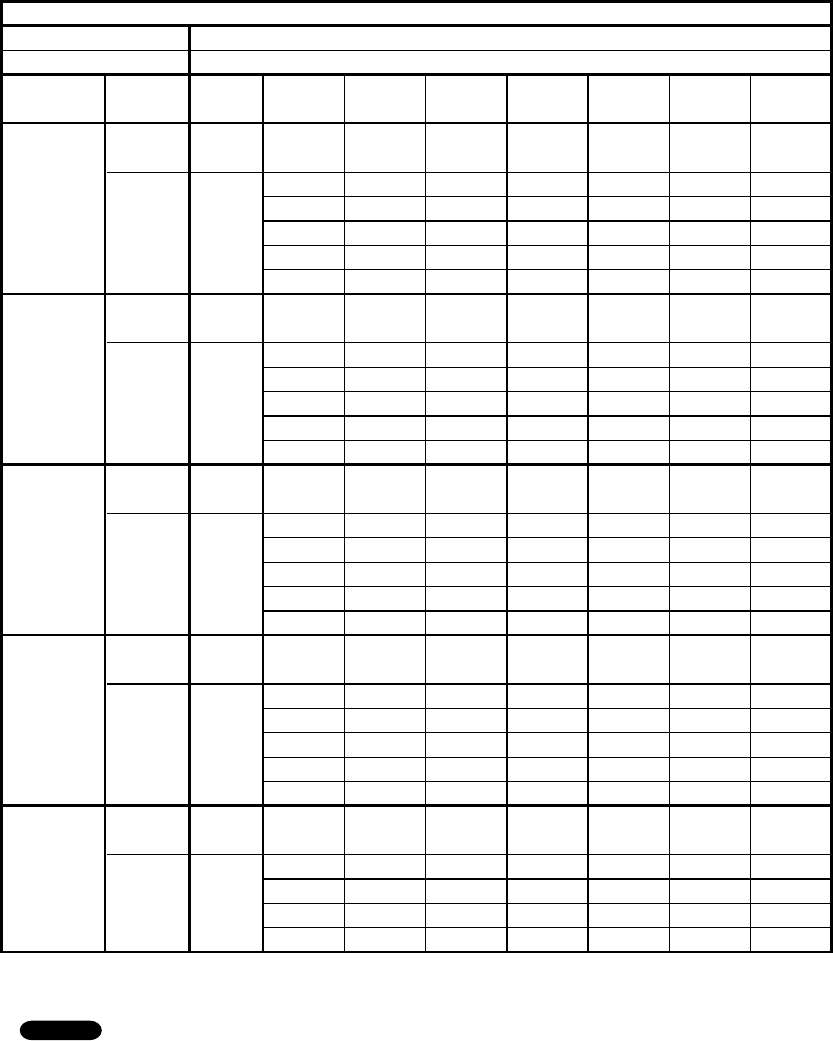
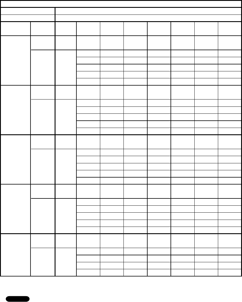
2-3. Other Component Specifications
Indoor UnitKS0971
KS1271
Outdoor UnitC0971C1271
CL0971CL1271
032 50 68 86 104 122 140 158 176 194
(0) (10) (20) (30) (40) (50) (60) (70) (80) (90)
40
60
80
100
120
140
160
180
200
20
50
1
0
2
3
4
5
6
7
8
9
10
59 68 77 86 95 104
(10) (15) (20) (25) (30) (35) (40)
Indoor air temp sensor
(Model:PTM-D51H-S3 TH2)
Indoor heat exchanger sensor
(Model:PTM-D51H-S3 TH1)
Compressor temp sensor
(Model:DTN-TKS274Y TH2)
Resistance (k ohm)
Resistance (k ohm)
Temperature °F (°C)
Outdoor air temp sensor
(Model:DTN-TKS269B)
Outdoor heat exchanger sensor
(Model:DTN-TKS274Y TH1)
40
35
30
25
20
15
10
5
0
-
4514 23 32 41 50 59 68
(
-
20)(
-
15)(
-
10) (
-
5) (0) (5) (10) (15) (20)
Resistance (k ohm)
Temperature °F (°C)
Temperature °F (°C)
16
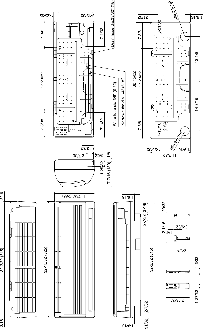
3. DIMENSIONAL DATA
Indoor Unit KS0971
KS1271
Unit: inch(mm)
17
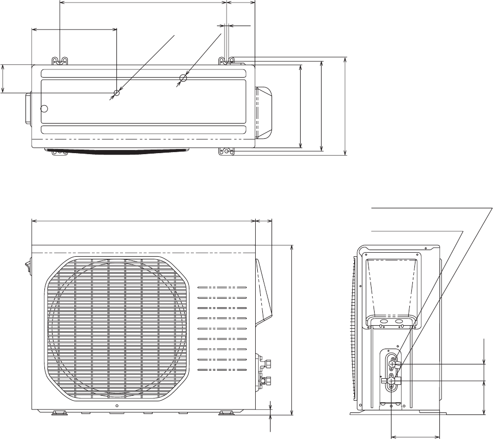
10-13/16
3-19/32
ID:23/32
2-ID:15/16
21-3/16
6-3/32
4-9/32 2-5/32
Narrow tube service valve
dia.1/4" (6.35)
Wide tube service valve
dia.3/8" (9.52)
3-19/32
15/32
10-7/16(265)
11-13/32
12-7/16
Unit: inch(mm)
28-11/32 (720) 2-1/8
21-9/16 (548)
5/8
Outdoor UnitC0971C1271
CL0971CL1271
18
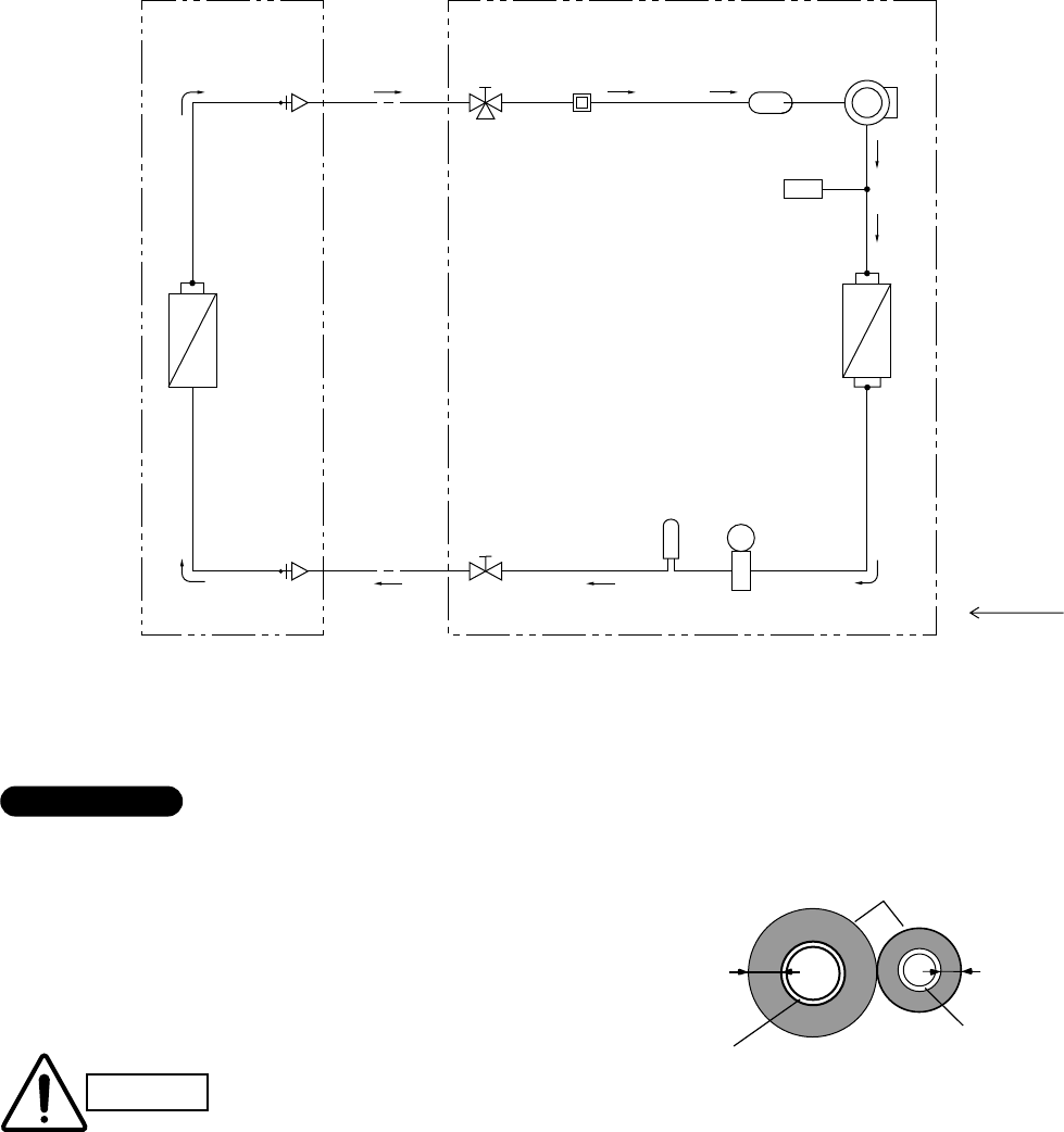
Compressor
Accumulator
Wide tube
service
valve
Wide tube
Narrow
tube
service
valve
Narrow tube
Heat exchanger
Heat exchanger
Muffler
Cooling cycle
Indoor unit Outdoor unit
Electric
expansion
valve
M
Muffler
*1
*1: 0nly for C1271/CL1271
O.D.
3/8"
(9.52 mm)
O.D.
1/4"
(6.35 mm)
H.P.
High pressure
switch
4. REFRIGERANT FLOW DIAGRAM
4-1. Refrigerant Flow Diagram
Indoor UnitKS0971
KS1271
Outdoor UnitC0971C1271
CL0971CL1271
Insulation of Refrigerant Tubing
Because capillary tubing is used in the outdoor unit, both the
wide and narrow tubes of this air conditioner become cold. To
prevent heat loss and wet floors due to dripping of
condensation, both tubes must be well insulated with a
proper insulation material. The thickness of the insulation
should be a min. 5/16"(8 mm).
After a tube has been insulated,
never try to bend it into a narrow
curve because it can cause the tube
to break or crack.
Wide tube
Thickness:
Min. 5/16"(8 mm)
Insulation
Narrow tube
Thickness:
Min. 5/16"(8 mm)
IMPORTANT
CAUTION
19
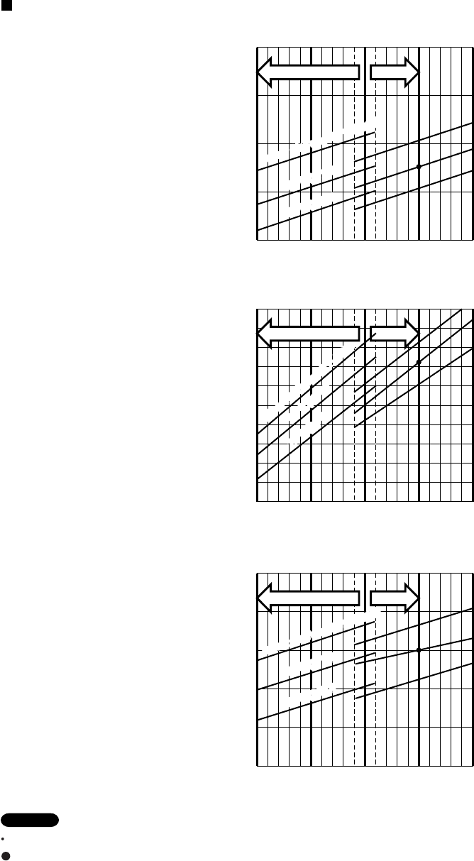
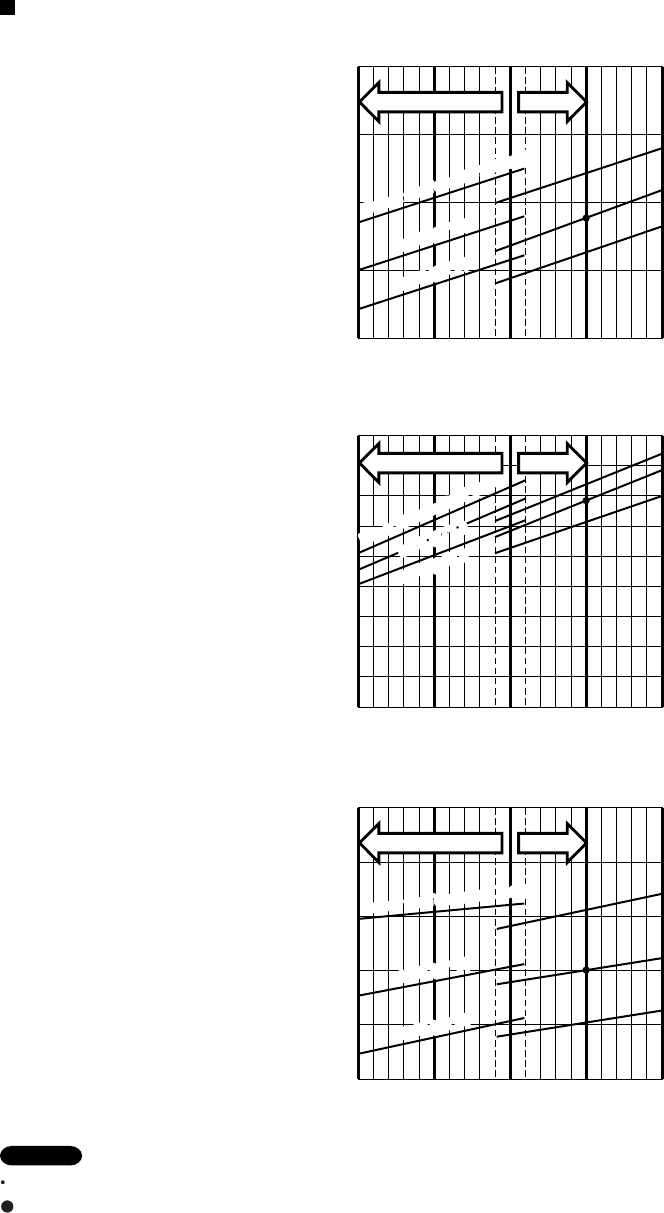
5. PERFORMANCE DATA
5-1. Temperature Charts
Indoor UnitKS0971 Outdoor UnitC0971
Check each performance value in test-run mode. Electrical performance values represent a combined indoor/outdoor value.
:Points of rating condition
Black dots in above charts indicate the following rating conditions.
NOTE
Cooling: Indoor air temperature 80 °F D.B. / 67 °F W.B. Outdoor air temperature 95 °F D.B.
Cooling Characteristics (RH : 46%, Indoor fan speed : High fan) (60Hz, 115V)
(1) Low pressure performance chart
(2) Operating current performance chart
(3) Indoor discharge air performance chart
68
(20)
77
(25)
86
(30)
95
(35)
104
(40)
60.8 (16)
64.4 (18)
57.2 (14)
53.6 (12)
50.0 (10)
46.4 (8)
Outdoor inlet air D.B. temp.°F(°C)
Outdoor inlet air D.B. temp.°F(°C)
Outdoor inlet air D.B. temp.°F(°C)
Operating current (A)
Indoor discharge air temperature °F(°C)
8
9
6
5
7
4
145
(1.0)
159
(1.1)
173
(1.2)
131
(0.9)
117
(0.8)
Low pressure at wide tube service valve
psig(MPaG)
Hi FanLo fan
68
(20)
77
(25)
86
(30)
95
(35)
104
(40)
80
°F (
27
°C)
75°F (24
°C)
Indoor Air Temp.86°F (30°C)
80
°F (
27
°C)
75°F (24
°C)
Indoor Air Temp.86°F (30°C)
68
(20)
77
(25)
86
(30)
95
(35)
104
(40)
80
°F (
27
°C)
75°F (24°C)
Indoor Air Temp.86°F (30°C)
80
°F (
27
°C)
75°F (24°C)
Indoor Air Temp.86°F (30°C)
80
°F (
27
°C)
75°F (24
°C)
Indoor Air Temp.86°F (30°C)
80
°F (
27
°C)
75°F (24
°C)
Indoor Air Temp.86°F (30°C)
Hi FanLo fan
Hi FanLo fan
20
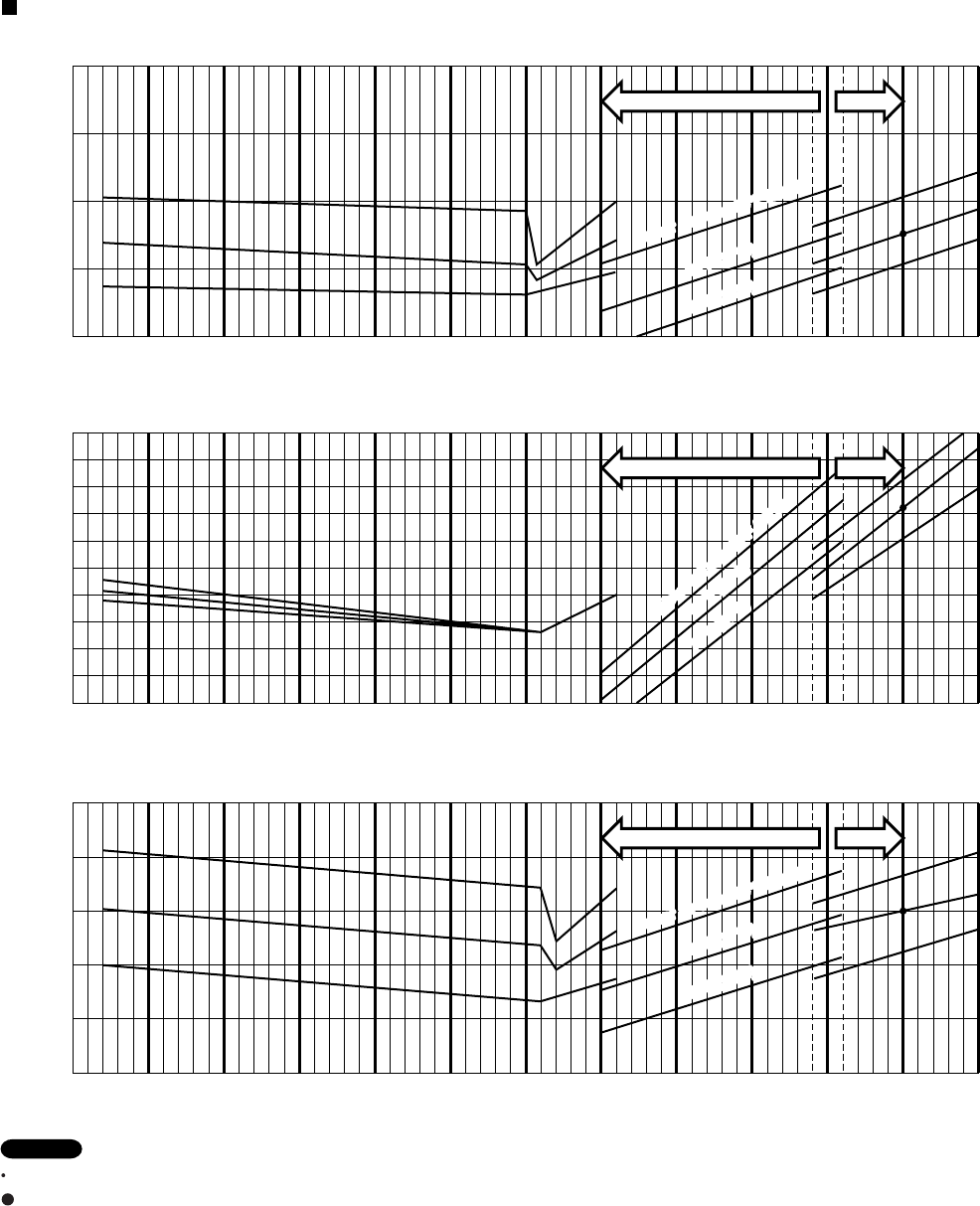
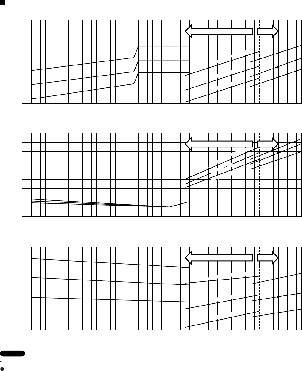
Indoor UnitKS0971 Outdoor UnitCL0971
Check each performance value in test-run mode. Electrical performance values represent a combined indoor/outdoor value.
:Points of rating condition
Black dots in above charts indicate the following rating conditions.
NOTE
Cooling: Indoor air temperature 80 °F D.B. / 67 °F W.B. Outdoor air temperature 95 °F D.B.
Cooling Characteristics (RH : 46%, Indoor fan speed : High fan) (60Hz, 115V)
(1) Low pressure performance chart
(2) Operating current performance chart
(3) Indoor discharge air performance chart
-4
(-20)
5
(-15)
14
(-10)
23
(-5)
32
(0)
41
(5)
50
(10)
59
(15)
68
(20)
77
(25)
86
(30)
95
(35)
104
(40)
60.8 (16)
64.4 (18)
57.2 (14)
53.6 (12)
50.0 (10)
46.4 (8)
Outdoor inlet air D.B. temp.°F(°C)
Outdoor inlet air D.B. temp.°F(°C)
Outdoor inlet air D.B. temp.°F(°C)
Operating current (A)
Indoor discharge air temperature °F(°C)
8
9
6
5
7
4
145
(1.0)
159
(1.1)
173
(1.2)
131
(0.9)
117
(0.8)
Low pressure at wide tube service valve
psig(MPaG)
Hi FanLo fan
-4
(-20)
5
(-15)
14
(-10)
23
(-5)
32
(0)
41
(5)
50
(10)
59
(15)
68
(20)
77
(25)
86
(30)
95
(35)
104
(40)
80
°F (
27
°C)
75°F (24
°C)
Indoor Air Temp.86°F (30°C)
80
°F (
27
°C)
75°F (24
°C)
Indoor Air Temp.86°F (30°C)
-4
(-20)
5
(-15)
14
(-10)
23
(-5)
32
(0)
41
(5)
50
(10)
59
(15)
68
(20)
77
(25)
86
(30)
95
(35)
104
(40)
Hi FanLo fan
Hi FanLo fan
80
°F (
27
°C)
75°F (24°C)
Indoor Air Temp.86°F (30°C)
80
°F (
27
°C)
75°F (24°C)
Indoor Air Temp.86°F (30°C)
80
°F (
27
°C)
75°F (24
°C)
Indoor Air Temp.86°F (30°C)
80
°F (
27
°C)
75°F (24
°C)
Indoor Air Temp.86°F (30°C)
21
Indoor UnitKS1271 Outdoor UnitC1271
Cooling Characteristics (RH : 46%, Indoor fan speed : High fan) (60Hz, 115V)
(1) Low pressure performance chart
(2) Operating current performance chart
(3) Indoor discharge air performance chart
68
(20)
77
(25)
86
(30)
95
(35)
104
(40)
60.8 (16)
64.4 (18)
57.2 (14)
53.6 (12)
50.0 (10)
46.4 (8)
Outdoor inlet air D.B. temp.°F(°C)
Outdoor inlet air D.B. temp.°F(°C)
Outdoor inlet air D.B. temp.°F(°C)
Operating current (A)
Indoor discharge air temperature °F(°C)
12
8
6
10
11
13
7
5
9
4
145
(1.0)
159
(1.1)
173
(1.2)
131
(0.9)
117
(0.8)
Low pressure at wide tube service valve
psig(MPaG)
Hi FanLo fan
68
(20)
77
(25)
86
(30)
95
(35)
104
(40)
80
°F (
27
°C)
75°F (24
°C)
Indoor Air Temp.86°F (30°C)
68
(20)
77
(25)
86
(30)
95
(35)
104
(40)
80
°F (
27
°C)
75°F (24
°C)
Indoor Air Temp.86°F (30°C)
Check each performance value in test-run mode. Electrical performance values represent a combined indoor/outdoor value.
:Points of rating condition
Black dots in above charts indicate the following rating conditions.
NOTE
Cooling: Indoor air temperature 80 °F D.B. / 67 °F W.B. Outdoor air temperature 95 °F D.B.
80°F (27°C)
75°F (24°C)
Indoor Air Temp.86°F (30°C)
Hi FanLo fan
Hi FanLo fan
22
Indoor UnitKS1271 Outdoor UnitCL1271
Cooling Characteristics (RH : 46%, Indoor fan speed : High fan) (60Hz, 115V)
(1) Low pressure performance chart
(2) Operating current performance chart
(3) Indoor discharge air performance chart
-4
(-20)
5
(-15)
14
(-10)
23
(-5)
32
(0)
41
(5)
50
(10)
59
(15)
68
(20)
77
(25)
86
(30)
95
(35)
104
(40)
60.8 (16)
64.4 (18)
57.2 (14)
53.6 (12)
50.0 (10)
46.4 (8)
Outdoor inlet air D.B. temp.°F(°C)
Outdoor inlet air D.B. temp.°F(°C)
Outdoor inlet air D.B. temp.°F(°C)
Operating current (A)
Indoor discharge air temperature °F(°C)
12
8
6
10
11
13
7
5
9
4
145
(1.0)
159
(1.1)
173
(1.2)
131
(0.9)
117
(0.8)
Low pressure at wide tube service valve
psig(MPaG)
Hi FanLo fan
-4
(-20)
5
(-15)
14
(-10)
23
(-5)
32
(0)
41
(5)
50
(10)
59
(15)
68
(20)
77
(25)
86
(30)
95
(35)
104
(40)
80
°F (
27
°C)
75°F (24
°C)
Indoor Air Temp.86°F (30°C)
-4
(-20)
5
(-15)
14
(-10)
23
(-5)
32
(0)
41
(5)
50
(10)
59
(15)
68
(20)
77
(25)
86
(30)
95
(35)
104
(40)
Hi FanLo fan
Hi FanLo fan
80°F (27°C)
75°F (24°C)
Indoor Air Temp.86°F (30°C)
80
°F (
27
°C)
75°F (24
°C)
Indoor Air Temp.86°F (30°C)
Check each performance value in test-run mode. Electrical performance values represent a combined indoor/outdoor value.
:Points of rating condition
Black dots in above charts indicate the following rating conditions.
NOTE
Cooling: Indoor air temperature 80 °F D.B. / 67 °F W.B. Outdoor air temperature 95 °F D.B.
23
Indoor Unit:KS0971
Outdoor Unit:C0971 / CL0971
Power Supply:115V Single Phase 60Hz
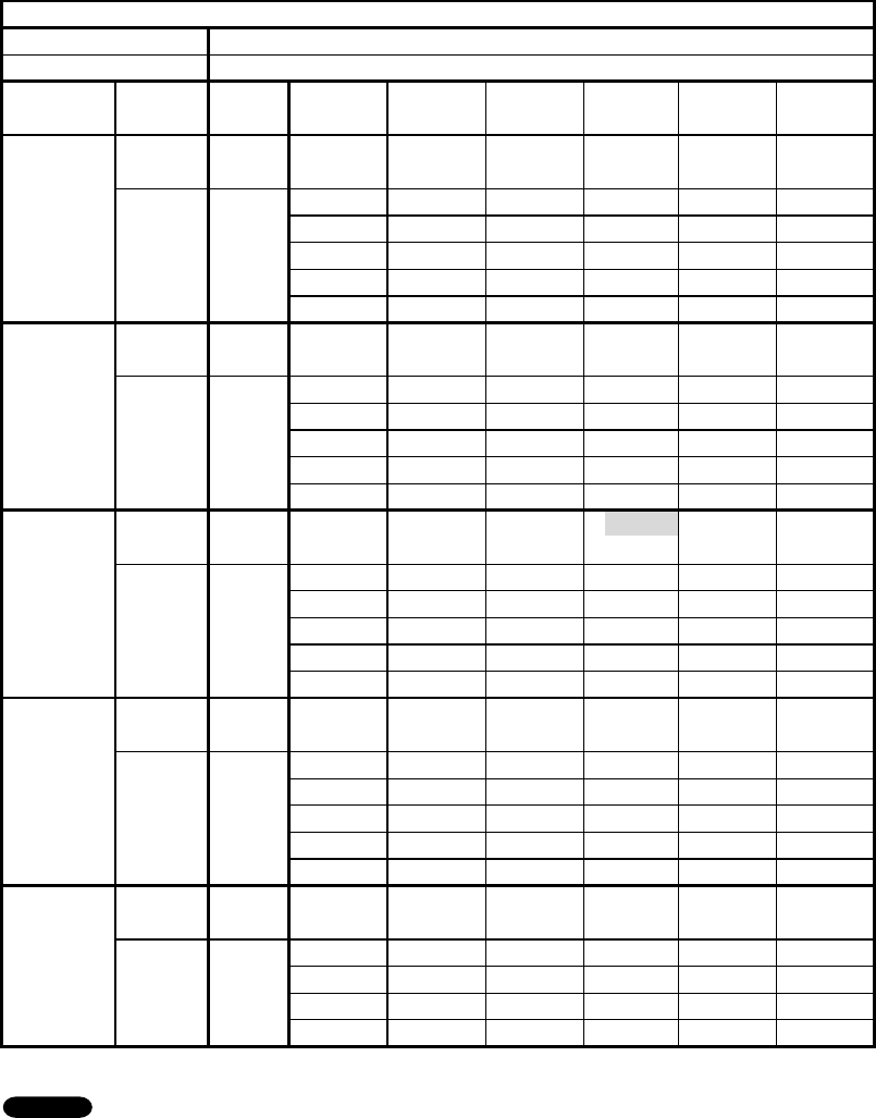
< Cooling Capacity >
5-2. Cooling Capacity
TC : Total Cooling Capacity (BTU/h) SHC : Sensible Heat Capacity (BTU/h)
1. Rating conditions (#) : Indoor Unit Entering Air Temp. 80 °F (26.7 °C) D.B. / 67 °F (19.4 °C) W.B.
: Outdoor Ambient Temp. 95 °F (35 °C) D.B.
2.
3. Above data represents the value when the operation frequency of a compressor is fixed.
Above data does not take Freeze Prevention Protection during cooling operation into account.
For this reason, the value may vary from the actual cooling characteristics.
NOTE
RATING CAPACITY: 9,000 BTU/h AIR FLOW RATE: 282 CFM
INDOOR OUTDOOR
ENT. TEMP. oF (oC) AMBIENT TEMP. oF (oC)
W.B. D.B. 65 75 85 95 105 115
(18.3) (23.9) (29.4) (35.0) (40.6) (46.1)
TC 9,080 8,800 8,500 8,260 7,890 6,400
72 (22.2) SHC 6,870 6,760 6,590 6,480 6,320 5,610
59 76 (24.4) SHC 7,860 7,690 7,580 7,470 7,250 6,400
(15.0) 80 (26.7) SHC 8,840 8,730 8,500 8,260 7,890 6,400
84 (28.9) SHC 9,080 8,800 8,500 8,260 7,890 6,400
88 (31.1) SHC 9,080 8,800 8,500 8,260 7,890 6,400
TC 9,440 9,160 8,860 8,630 8,250 6,580
72 (22.2) SHC 5,770 5,610 5,500 5,390 5,220 4,510
63 76 (24.4) SHC 6,700 6,590 6,430 6,370 6,160 5,500
(17.2) 80 (26.7) SHC 7,690 7,580 7,470 7,360 7,200 6,480
84 (28.9) SHC 8,680 8,570 8,400 8,300 8,130 6,580
88 (31.1) SHC 9,440 9,160 8,860 8,630 8,250 6,580
TC 9,790 9,520 9,220 # 9,000 8,620 6,740
72 (22.2) SHC 4,620 4,450 4,350 4,290 4,130 3,410
67 76 (24.4) SHC 5,550 5,440 5,330 5,220 5,060 4,350
(19.4) 80 (26.7) SHC 6,540 6,430 6,320 6,210 6,100 5,330
84 (28.9) SHC 7,530 7,420 7,310 7,200 7,030 6,320
88 (31.1) SHC 8,460 8,350 8,240 8,190 8,020 6,740
TC 10,120 9,860 9,560 9,360 8,980 6,890
72 (22.2) SHC 3,360 3,250 3,140 3,080 2,920 2,210
71 76 (24.4) SHC 4,350 4,240 4,130 4,020 3,910 3,190
(21.7) 80 (26.7) SHC 5,330 5,220 5,110 5,060 4,890 4,180
84 (28.9) SHC 6,270 6,210 6,100 5,990 5,880 5,110
88 (31.1) SHC 7,250 7,140 7,030 6,980 6,810 6,100
TC 10,400 10,140 9,840 9,680 9,300 7,010
75 76 (24.4) SHC 3,140 3,030 2,920 2,860 2,750 2,040
(23.9) 80 (26.7) SHC 4,130 4,070 3,960 3,910 3,800 3,030
84 (28.9) SHC 5,110 5,000 4,890 4,840 4,730 4,020
88 (31.1) SHC 6,050 5,990 5,880 5,830 5,720 4,950
24
Indoor Unit:KS1271
Outdoor Unit:C1271 / CL1271
Power Supply:115V Single Phase 60Hz
< Cooling Capacity >
TC : Total Cooling Capacity (BTU/h) SHC : Sensible Heat Capacity (BTU/h)
1. Rating conditions (#) : Indoor Unit Entering Air Temp. 80 °F (26.7 °C) D.B. / 67 °F (19.4 °C) W.B.
: Outdoor Ambient Temp. 95 °F (35 °C) D.B.
2.
3. Above data represents the value when the operation frequency of a compressor is fixed.
Above data does not take Freeze Prevention Protection during cooling operation into account.
For this reason, the value may vary from the actual cooling characteristics.
NOTE
RATING CAPACITY: 11,900 BTU/h AIR FLOW RATE: 294 CFM
INDOOR OUTDOOR
ENT. TEMP. oF (oC) AMBIENT TEMP. oF (oC)
W.B. D.B. 65 75 85 95 105 115
(18.3) (23.9) (29.4) (35.0) (40.6) (46.1)
TC 11,970 11,660 11,310 11,050 10,620 8,860
72 (22.2) SHC 8,480 8,300 8,130 7,960 7,730 6,880
59 76 (24.4) SHC 9,450 9,280 9,100 8,990 8,760 7,850
(15.0) 80 (26.7) SHC 10,530 10,360 10,130 10,020 9,790 8,860
84 (28.9) SHC 11,500 11,330 11,160 10,990 10,620 8,860
88 (31.1) SHC 11,970 11,660 11,310 11,050 10,620 8,860
TC 12,370 12,070 11,730 11,480 11,050 9,020
72 (22.2) SHC 7,220 7,050 6,880 6,760 6,530 5,620
63 76 (24.4) SHC 8,190 8,020 7,850 7,730 7,560 6,590
(17.2) 80 (26.7) SHC 9,220 9,100 8,930 8,820 8,590 7,680
84 (28.9) SHC 10,250 10,080 9,900 9,790 9,560 8,650
88 (31.1) SHC 11,220 11,050 10,880 10,760 10,590 9,020
TC 12,740 12,450 12,120 # 11,900 11,470 9,160
72 (22.2) SHC 5,900 5,730 5,620 5,500 5,330 4,360
67 76 (24.4) SHC 6,880 6,760 6,590 6,530 6,300 5,330
(19.4) 80 (26.7) SHC 7,900 7,790 7,620 7,560 7,330 6,420
84 (28.9) SHC 8,930 8,760 8,650 8,530 8,360 7,390
88 (31.1) SHC 9,900 9,790 9,620 9,560 9,330 8,360
TC 13,080 12,800 12,470 12,290 11,870 9,270
72 (22.2) SHC 4,480 4,360 4,250 4,190 4,020 3,050
71 76 (24.4) SHC 5,500 5,390 5,220 5,160 4,990 4,020
(21.7) 80 (26.7) SHC 6,530 6,420 6,300 6,190 6,080 5,050
84 (28.9) SHC 7,500 7,390 7,280 7,220 7,050 6,080
88 (31.1) SHC 8,530 8,420 8,300 8,190 8,020 7,050
TC 13,320 13,060 12,750 12,610 12,210 9,330
75 76 (24.4) SHC 4,130 4,020 3,960 3,900 3,730 2,760
(23.9) 80 (26.7) SHC 5,160 5,100 4,990 4,930 4,760 3,790
84 (28.9) SHC 6,190 6,080 5,960 5,900 5,790 4,820
88 (31.1) SHC 7,160 7,100 6,990 6,930 6,760 5,790
25
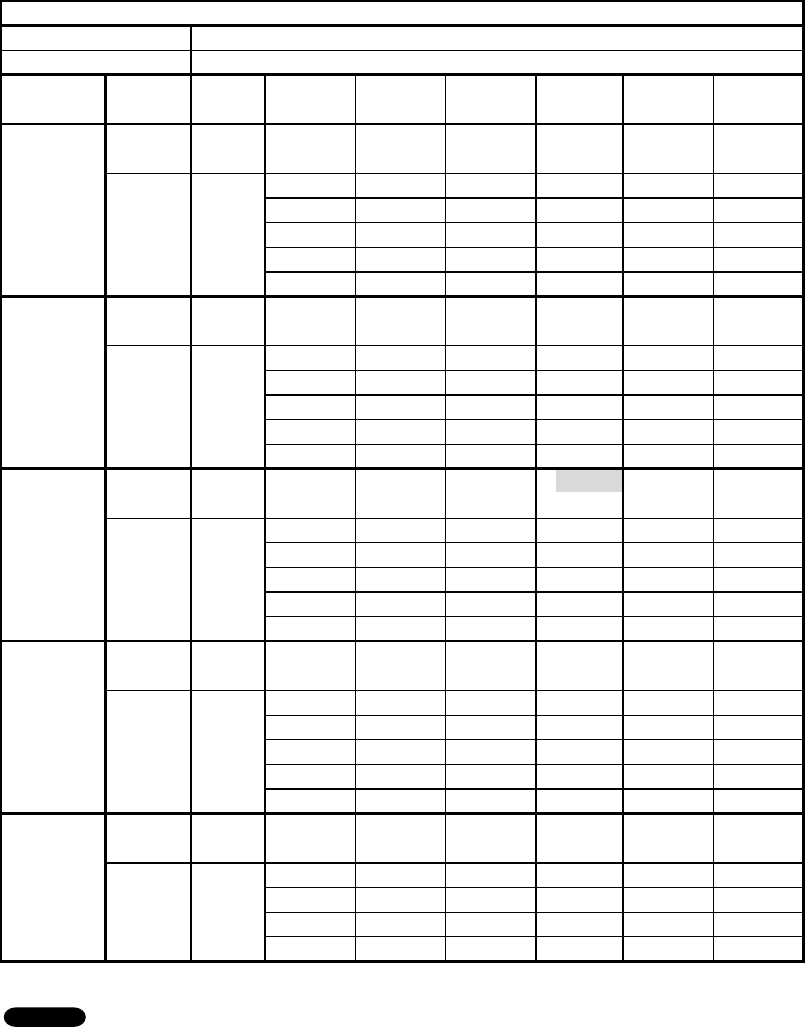
Indoor Unit:KS0971
Outdoor Unit:CL0971
Power Supply:115V Single Phase 60Hz
< Cooling Capacity (Low Ambient) >
5-3. Cooling Capacity (Low Ambient)
TC : Total Cooling Capacity (BTU/h) SHC : Sensible Heat Capacity (BTU/h)
1.
2. Above data represents the value when the operation frequency of a compressor is fixed.
Above data does not take Freeze Prevention Protection during cooling operation into account.
For this reason, the value may vary from the actual cooling characteristics.
NOTE
RATING CAPACITY: 9,000 BTU/h AIR FLOW RATE: 282 CFM
INDOOR OUTDOOR
ENT. TEMP. oF (oC) AMBIENT TEMP. oF (oC)
W.B. D.B. 0515 25 35 45 55
(-17.8) (-15.0) (-9.4) (-3.9) (1.7) (7.2) (12.8)
TC 9,770 9,790 9,760 9,800 9,840 9,850 9,780
72 (22.2) SHC 7,250 7,250 7,250 7,250 7,250 7,310 7,250
59 76 (24.4) SHC 8,190 8,240 8,190 8,240 8,240 8,240 8,190
(15.0) 80 (26.7) SHC 9,230 9,230 9,230 9,230 9,230 9,230 9,230
84 (28.9) SHC 9,770 9,790 9,760 9,800 9,840 9,850 9,780
88 (31.1) SHC 9,770 9,790 9,760 9,800 9,840 9,850 9,780
TC 9,670 9,700 9,760 9,860 9,960 10,010 9,980
72 (22.2) SHC 5,880 5,880 5,880 5,940 5,990 5,990 5,990
63 76 (24.4) SHC 6,810 6,810 6,870 6,920 6,980 6,980 6,980
(17.2) 80 (26.7) SHC 7,800 7,860 7,860 7,910 7,970 7,970 7,970
84 (28.9) SHC 8,790 8,790 8,840 8,900 8,900 8,950 8,950
88 (31.1) SHC 9,670 9,700 9,760 9,830 9,890 9,890 9,890
TC 9,460 9,510 9,660 9,840 10,010 10,120 10,120
72 (22.2) SHC 4,450 4,450 4,560 4,620 4,670 4,730 4,730
67 76 (24.4) SHC 5,440 5,440 5,500 5,550 5,660 5,720 5,720
(19.4) 80 (26.7) SHC 6,430 6,430 6,480 6,590 6,650 6,700 6,700
84 (28.9) SHC 7,360 7,420 7,470 7,530 7,640 7,640 7,640
88 (31.1) SHC 8,350 8,350 8,400 8,510 8,570 8,620 8,620
TC 9,100 9,170 9,440 9,730 9,980 10,160 10,210
72 (22.2) SHC 2,970 3,030 3,080 3,190 3,300 3,360 3,410
71 76 (24.4) SHC 3,960 3,960 4,070 4,180 4,290 4,350 4,350
(21.7) 80 (26.7) SHC 4,950 5,000 5,060 5,170 5,280 5,330 5,390
84 (28.9) SHC 5,940 5,940 6,050 6,160 6,210 6,320 6,320
88 (31.1) SHC 6,870 6,920 6,980 7,090 7,200 7,250 7,310
TC 8,630 8,720 9,130 9,530 9,880 10,120 10,220
75 76 (24.4) SHC 2,530 2,590 2,700 2,860 2,970 3,030 3,080
(23.9) 80 (26.7) SHC 3,580 3,580 3,740 3,850 3,960 4,020 4,070
84 (28.9) SHC 4,510 4,560 4,670 4,780 4,950 5,000 5,060
88 (31.1) SHC 5,500 5,500 5,660 5,770 5,880 5,990 5,990
26
Indoor Unit:KS1271
Outdoor Unit:CL1271
Power Supply:115V Single Phase 60Hz
< Cooling Capacity (Low Ambient) >
TC : Total Cooling Capacity (BTU/h) SHC : Sensible Heat Capacity (BTU/h)
1.
2. Above data represents the value when the operation frequency of a compressor is fixed.
Above data does not take Freeze Prevention Protection during cooling operation into account.
For this reason, the value may vary from the actual cooling characteristics.
NOTE
RATING CAPACITY: 11,900 BTU/h AIR FLOW RATE: 294 CFM
INDOOR OUTDOOR
ENT. TEMP. oF (oC) AMBIENT TEMP. oF (oC)
W.B. D.B. 0515 25 35 45 55
(-17.8) (-15.0) (-9.4) (-3.9) (1.7) (7.2) (12.8)
TC 9,660 9,670 9,680 9,710 9,730 9,720 9,670
72 (22.2) SHC 7,280 7,280 7,280 7,280 7,280 7,280 7,280
59 76 (24.4) SHC 8,250 8,250 8,250 8,300 8,300 8,300 8,250
(15.0) 80 (26.7) SHC 9,280 9,280 9,330 9,330 9,330 9,330 9,280
84 (28.9) SHC 9,660 9,670 9,680 9,710 9,730 9,720 9,670
88 (31.1) SHC 9,660 9,670 9,680 9,710 9,730 9,720 9,670
TC 9,610 9,620 9,700 9,780 9,840 9,870 9,840
72 (22.2) SHC 5,900 5,900 5,900 5,960 5,960 6,020 5,960
63 76 (24.4) SHC 6,880 6,880 6,930 6,930 6,990 6,990 6,990
(17.2) 80 (26.7) SHC 7,900 7,900 7,960 8,020 8,020 8,020 8,020
84 (28.9) SHC 8,930 8,930 8,930 8,990 8,990 9,050 8,990
88 (31.1) SHC 9,610 9,620 9,700 9,780 9,840 9,870 9,840
TC 9,460 9,490 9,640 9,770 9,890 9,960 9,970
72 (22.2) SHC 4,480 4,480 4,530 4,590 4,650 4,700 4,700
67 76 (24.4) SHC 5,450 5,500 5,560 5,620 5,680 5,680 5,680
(19.4) 80 (26.7) SHC 6,530 6,530 6,590 6,650 6,700 6,700 6,700
84 (28.9) SHC 7,500 7,500 7,560 7,620 7,680 7,730 7,730
88 (31.1) SHC 8,480 8,530 8,590 8,650 8,700 8,700 8,700
TC 9,190 9,240 9,480 9,680 9,860 9,980 10,030
72 (22.2) SHC 2,990 3,050 3,100 3,160 3,280 3,280 3,330
71 76 (24.4) SHC 4,020 4,020 4,130 4,190 4,250 4,300 4,300
(21.7) 80 (26.7) SHC 5,050 5,050 5,160 5,220 5,280 5,330 5,330
84 (28.9) SHC 6,020 6,080 6,130 6,190 6,300 6,300 6,360
88 (31.1) SHC 7,050 7,050 7,160 7,220 7,280 7,330 7,330
TC 8,840 8,900 9,240 9,520 9,760 9,940 10,020
75 76 (24.4) SHC 2,590 2,650 2,760 2,820 2,930 2,990 2,990
(23.9) 80 (26.7) SHC 3,680 3,680 3,790 3,850 3,960 4,020 4,020
84 (28.9) SHC 4,650 4,650 4,760 4,880 4,930 4,990 5,050
88 (31.1) SHC 5,620 5,680 5,790 5,850 5,960 6,020 6,020
27
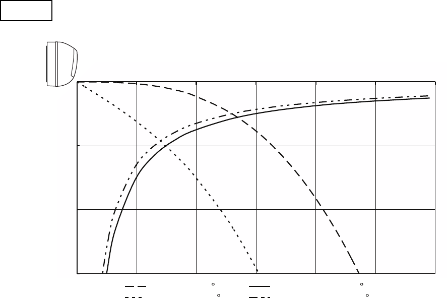
Horizontal distance (ft.)
Axis air velocity (ft./sec.)
Vertical distance (ft.)
Room air temp. : 80°F (26.7°C)
Fan speed : High
Cooling
: Flap angle 0 , : Axis air velocity 0
: Flap angle 30 , : Axis air velocity 30
5-4. Air Throw Distance Charts
Indoor UnitKS0971
0
5
10
15
0 5 10 15 20 25 30
: Flap angle 0 , : Axis air velocity 0
: Flap angle 30, : Axis air velocity 30
28
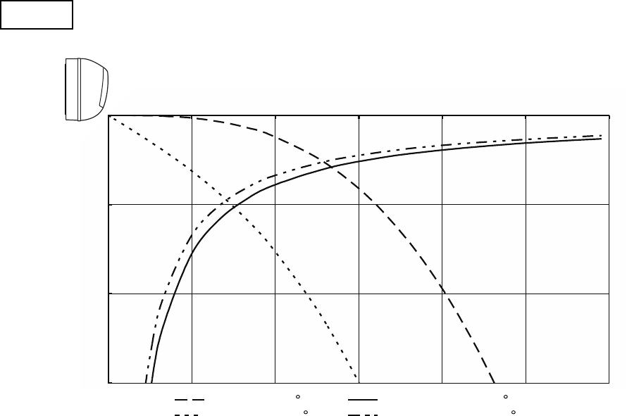
Horizontal distance (ft.)
Axis air velocity (ft./sec.)
Vertical distance (ft.)
Room air temp. :80°F (26.7°C)
Fan speed : High
Cooling
: Flap angle 0 , : Axis air velocity 0
: Flap angle 30 , : Axis air velocity 30
Indoor UnitKS1271
0
5
10
15
0 5 10 15 20 25 30
: Flap angle 0 , : Axis air velocity 0
: Flap angle 30, : Axis air velocity 30
29
6. ELECTRICAL DATA
6-1. Electrical Characteristics
Indoor UnitKS0971
Outdoor UnitC0971
Indoor Unit Outdoor Unit Complete Unit
Fan Motor Fan Motor + Compressor
Performance at 115V Single-phase 60Hz
Rating conditions Running amp. A 0.45
Power input W
A
W
45
7.15
705
Rating conditions:Indoor air temperature:80°F (26.7°C) D.B. / 67°F (19.4°C) W.B.
Outdoor air temperature:95°F (35°C) D.B.
Cooling
7.6
750
Indoor Unit KS0971
Outdoor Unit CL0971
Indoor Unit Outdoor Unit Complete Unit
Fan Motor Fan Motor + Compressor
Performance at 115V Single-phase 60Hz
Rating conditions Running amp. 0.45
Power input 45
7.15
705
Cooling
7.6
750
Rating conditions:Indoor air temperature:80°F (26.7°C) D.B. / 67°F (19.4°C) W.B.
Outdoor air temperature:95°F (35°C) D.B.
30

Indoor UnitKS1271
Outdoor UnitC1271
Indoor Unit Outdoor Unit Complete Unit
Fan Motor Fan Motor + Compressor
Performance at 115V Single-phase 60Hz
Rating conditions Running amp. 0.45
Power input 45
10.45
1,045
Rating conditions:Indoor air temperature:80°F (26.7°C) D.B. / 67°F (19.4°C) W.B.
Outdoor air temperature:95°F (35°C) D.B.
Cooling
10.9
1,090
Indoor Unit KS1271
Outdoor Unit CL1271
Indoor Unit Outdoor Unit Complete Unit
Fan Motor Fan Motor + Compressor
Performance at 115V Single-phase 60Hz
Rating conditions Running amp. 0.45
Power input 45
10.45
1,045
Cooling
10.9
1,090
Rating conditions:Indoor air temperature:80°F (26.7°C) D.B. / 67°F (19.4°C) W.B.
Outdoor air temperature:95°F (35°C) D.B.
A
W
A
W
31
EVAPORATOR TERMINAL BASE
TO OUTDOOR UNIT
GRN/YEL
LAMP
10P(WHT)
FLAP
5P (WHT)
FLAP
CONNECTOR
FLAP MOTOR
RED
PNK
BLU
BRN
YEL
1
2
3
4
5
1
2
3
4
5
1
2
3
4
5
1
2
3
4
5
AC
5P (BLU)
WHT
RED
WHT
WHT
WHT
WHT
WHT
WHT
WHT
WHT
1
2
3
4
5
6
7
8
9
10
1
2
3
4
5
6
7
8
9
10
1
2
3
4
5
6
7
8
9
10
1
2
3
4
5
6
7
8
9
10
IND LAMP ASSY
ROOM/COIL
4P(WHT)
FAN
5P (WHT)
HALL IC
3P (WHT)
FMC
3P (WHT)
CONTROLLER
FM
GRN/YEL
FAN MOTOR
CAPACITOR
FAN MOTOR
1
3
5
1
2
3
1
3
5
1
2
3
ROOM THERMISTOR
BLK
BLK
BLK
WHT
RED
BLK
BLK
1
2
3
4
1
2
3
4
COIL THERMISTOR
ION
3P (WHT)
HA
JEM-A
1
2
3
1
2
3
1
2
3
1
2
3
4P (WHT)
1 2 4
BLK
3
BLK
BLK
RED
WHT
1 2 3 4
1 2 3 4
ION ASSY
ION
TERMINAL
1 3 5
1 3 5
1
2
3
WHT
BLK
RED
1
3
1
3
BRN
PNK
(RED)
WHT
BLK
RED
YEL
BRN
PNK CONNECTOR
8FA2-5257-71600-0
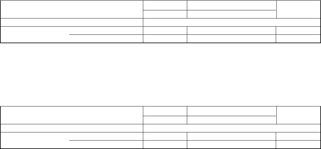
6-2. Electric Wiring Diagrams
Indoor UnitKS0971KS1271
WARNING
To avoid electrical shock hazard, be sure to
disconnect power before checking, servicing
and/or cleaning any electrical parts.
32
8FA2-5257-69000-2
REACTANCE
NL
GND
1
2
3
4
5
6
POWER
SUPPLY
321
1 2 3
CM
COMPRESSOR
MOTOR
RED (PNK)
WHT
BLU
RED
(PNK)
WHT
BLU
FERRITE
CORE 3P
-
CONNECTOR (WHT)
S/UC/W
R/V
W W
W
W
W
W
CONTROLLER
1 2 3 4
1 2 3 4
5
5
6
6
1 2 3 4
1 2 3 4
5
5
6
6
1 2 3 4
1 2 3 4
1 2
1 2
L2
W
L1 E
25A ACIN1
W
ACIN2
W
SI
MV
DCFM
OUTDOOR
COIL/COMP
U
W
V
2P-CONNECTOR (BLK)
YEL
ORG
YEL
ORG
GRN/YEL
1
1
2
2
FERRITE
CORE TERMINAL
PLATE
GND
TO INDOOR UNIT
POWER RELAY
61
4
5
BLK
WHT
RED
BLK
BLK
BLK
WHT
1 2 3 4 5 6 7
FM
GRN/YEL
FAN MOTOR
1 2 3 4 5 6 7
1 2 3 4 5 6 7 BLK
BLK
YEL
YEL
YEL
BLK
BLK
BLU
RED
BLK
BLK
BLK
WHT
YEL
BLU
RED
BLK
BLK
YEL
WHT
GRY
RED
ORG
WHT
OUT DOOR
THERMISTOR
OVERLOAD RELAY
(OLR)
COIL
THERMISTOR
COMPRESSOR
THERMISTOR
7P-CONNECTOR (WHT)
MV
MAGNETIC COIL
2P-CONNECTOR (BLK)
2P-CONNECTOR (WHT)
HIGH PRESSURE
SWITCH
1 1
2 2
WHT
WHT
WHT
WHT
1 1
2 2
WHT
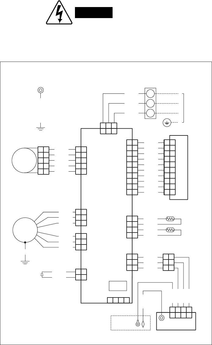
Outdoor UnitC0971C1271
WARNING
To avoid electrical shock hazard, be sure to
disconnect power before checking, servicing
and/or cleaning any electrical parts.
33
8FA2-5257-69300-2
REACTANCE
NL
GND
1
2
3
4
5
6
POWER
SUPPLY
321
1 2 3
CM
COMPRESSOR
MOTOR
RED (PNK)
WHT
BLU
RED
(PNK)
WHT
BLU
FERRITE
CORE 3P
-
CONNECTOR (WHT)
S/UC/W
R/V
W W
W
W
W
W
CONTROLLER
1 2 3 4
1 2 3 4
5
5
6
6
1 2 3 4
1 2 3 4
5
5
6
6
1 2 3 4
1 2 3 4
1 2
1 2
L2
W
L1 E
25A ACIN1
W
ACIN2
W
SI
MV
DCFM
OUTDOOR
COIL/COMP
U
W
V
2P-CONNECTOR (BLK)
YEL
ORG
YEL
ORG
GRN/YEL
1
1
2
2
FERRITE
CORE TERMINAL
PLATE
GND
TO INDOOR UNIT
POWER RELAY
61
4
5
BLK
WHT
RED
BLK
BLK
BLK
WHT
1 2 3 4 5 6 7
FM
GRN/YEL
FAN MOTOR
1 2 3 4 5 6 7
1 2 3 4 5 6 7 BLK
BLK
YEL
YEL
YEL
BLK
BLK
BLU
RED
BLK
BLK
BLK
WHT
YEL
BLU
RED
BLK
BLK
YEL
WHT
GRY
RED
ORG
WHT
OUT DOOR
THERMISTOR
OVERLOAD RELAY
(OLR)
COIL
THERMISTOR
COMPRESSOR
THERMISTOR
7P-CONNECTOR (WHT)
MV
MAGNETIC COIL
2P-CONNECTOR (BLK)
2P-CONNECTOR (WHT)
HIGH PRESSURE
SWITCH
1 1
2 2
WHT
WHT
WHT
WHT
1 1
2 2
WHT
W W
C-HEATER1C-HEATER2
1P-CONNECTOR (WHT)
1P-CONNECTOR (WHT)
WHT
WHT
WHT
WHT
1 1
1 1
CRANKCASE
HEATER
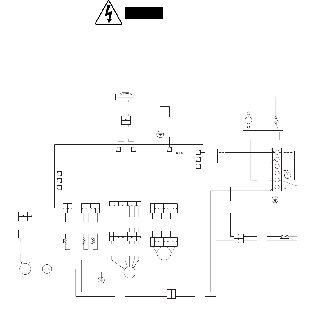
Outdoor UnitCL0971CL1271
WARNING
To avoid electrical shock hazard, be sure to
disconnect power before checking, servicing
and/or cleaning any electrical parts.
34
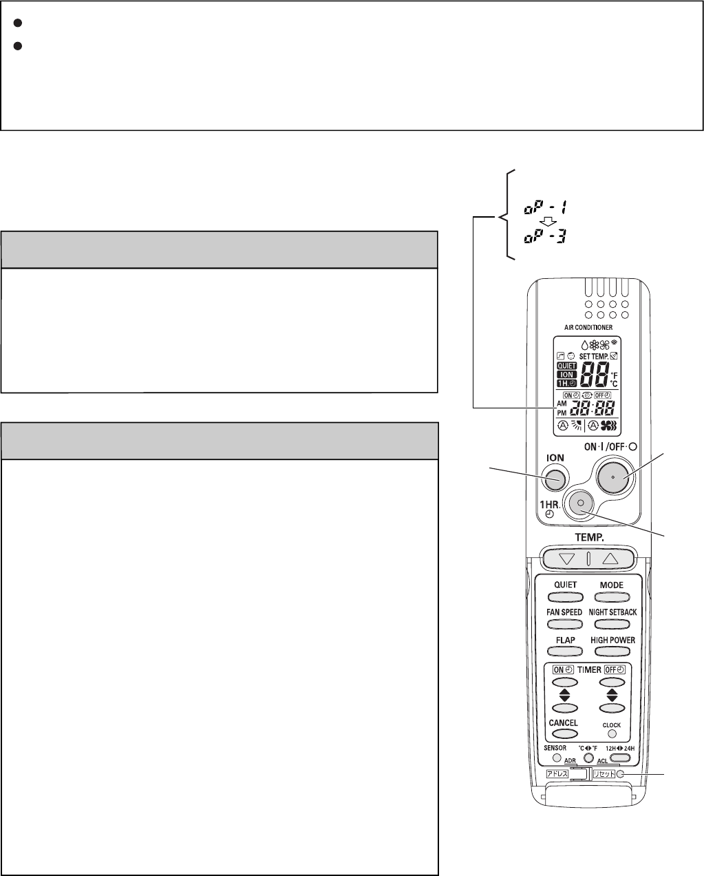
1HR.
TIMER
button
ON/OFF
operation
button
ACL
(Reset)
button
ION
button
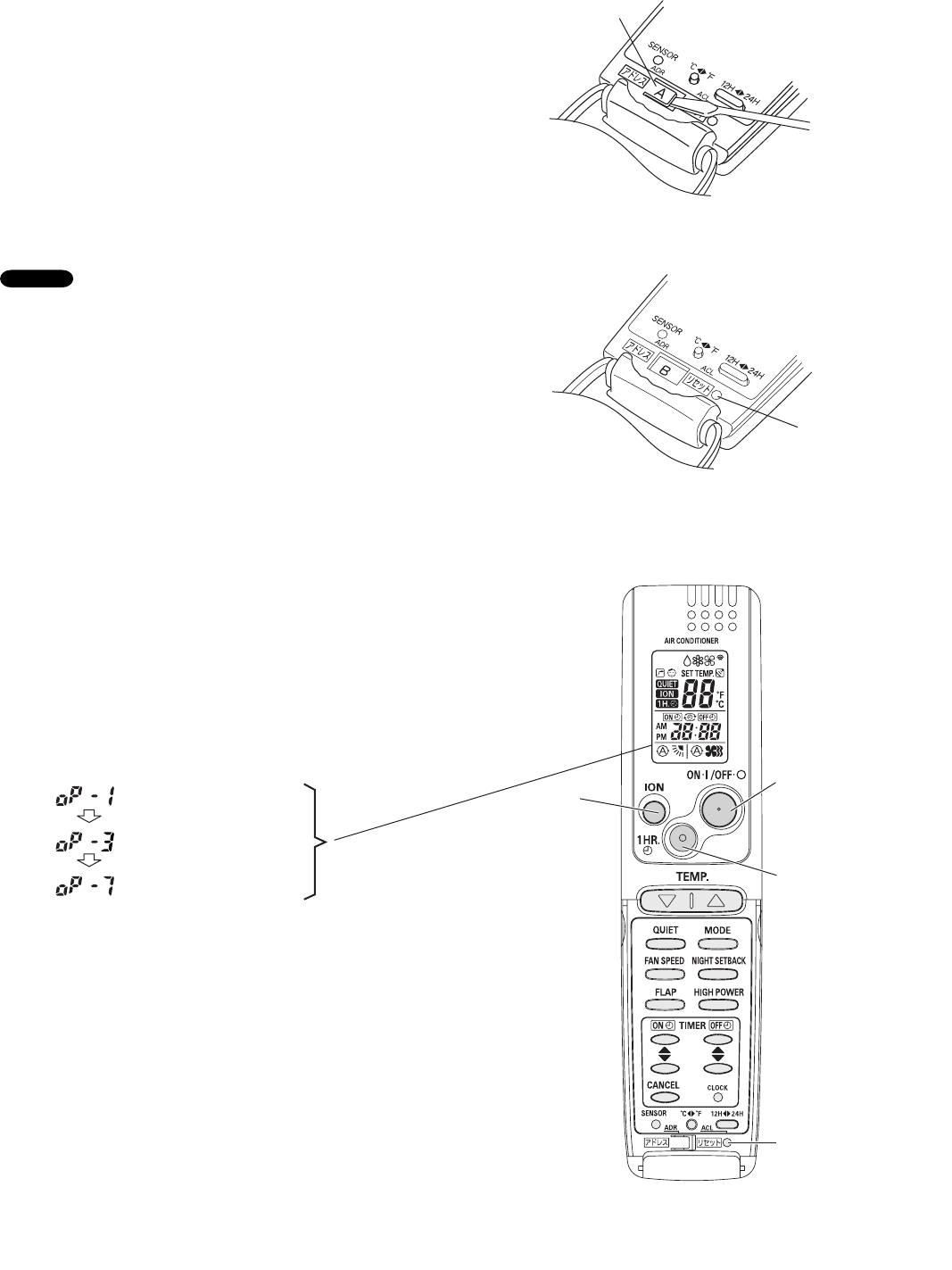
7. MAINTENANCE
7-1. Address Setting of the Remote
Control Unit
The address can be set in order to prevent
interference between remote controllers when two
Sanyo indoor units are installed near each other. The
address is normally set to "A." To set a different
address, it is necessary to change the address on the
second remote controller.
Once changed, you cannot restore the original
address setting of the air conditioner.
(1) Switch on the power source.
(2) Break the address-setting tab marked "A" on the
second remote controller to change the address
(Fig. 13). When the tab is removed, the address is
automatically set to B (Fig. 14).
(3) Press and hold the remote controller ION button
and 1 HR TIMER button. Then, press and hold
the ACL (reset) button with a pointed object such
as the tip of a pen. After 5 seconds, release ACL
button first, then release ION and 1 HR TIMER
buttons, "oP-1" (test run) appears, blinking in the
remote controller clock display area.
(4) Each time the 1 HR TIMER button is pressed, the
display changes as shown below. Press this
button 2 times to change the display to "oP-7"
(address setting). (Fig. 15)
(5) "oP-7" has now been selected for address setting.
(6) Press the ON/OFF operation button on the remote
controller. (Fig. 15) Check that the "beep"signal-
received sound is heard from the second indoor
unit (approximately 5 times). The sound you hear
is the signal that the remote controller address
has been changed.
(7) Finally press the remote controller ACL (reset)
button to cancel the blinking "oP-7" display. (Fig.
15)
Changing of the second remote controller address is
now completed.
NOTE
Fig. 13
Fig. 14
Fig. 15
Tab
ACL button
Test run mode
Self-diagnostic mode
Address setting mode
35
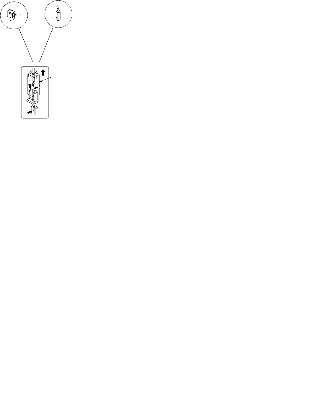
One of the two types of connectors illustrated at left is used. Their
basic structure is the same for each.
How to Disconnect
Hold the resin connector cover, and pull the connector off.
You cannot disconnect the connector by pulling the wire since
it is locked inside. Always hold the cover to disconnect. (See
illustration at left.) For the connector without the resin cover,
push the lock in the direction of "2" while pulling it off.
How to Connect
In order to connect, hold the resin cover of the connector and
push it in. Confirm the click sound for the inside lock.
Pull the cover upward
When the cover is pulled upward, the lock is
released with the sequence of 1 and 2.
7-2. Disconnecting and Connecting Positive Connector for Outdoor Unit
36
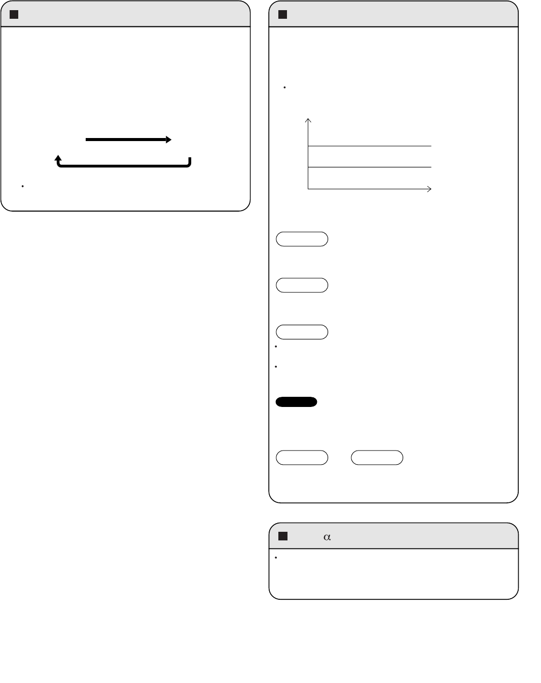
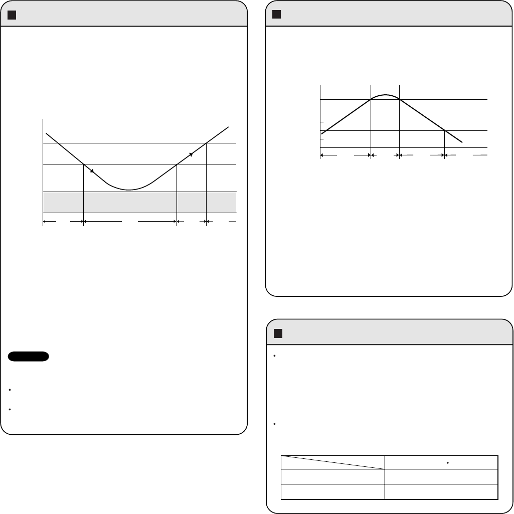
Emergency operation SENSOR DRY
During DRY operation, the system adjusts the room
temperature and fan speed according to the conditions in the
room, in order to maintain a comfortable room environment.
SENSOR DRY operation
DRY operation is as shown in the figure below.
PAM- control
In order to further improve inverter performance, control is
switched between PWM control at low operation speeds, and
PAM control at high operation speeds, making the most
effective use of power.
The compressor operation frequency varies.
The indoor fan operates with 1/f fluctuation.
The compressor operates at a low operating frequency.
The indoor fan operates with 1/f fluctuation.
Monitoring operation takes place when the room temperature
is below 59°F(15°C), or more than 5°F(3°C) below the set
temperature.
When the monitoring range is entered, the compressor stops,
and the indoor fan operates with 1/f fluctuation.
DRY A
DRY B
Monitor
Conditions are monitored at all
times when the room temperature
is below 59°F(15°C).
Load
COOL zone
A zone
B zone
Emergency operation is available when the remote
controller malfunctions, has been lost, or otherwise
cannot be used.
The set temperature is 4°F(2°C) below the detected room
temperature in the case of cooling operation.
(GREEN) (Lamp Off)
COOL STOP
To operate the system, press the OPERATION button,
which is also used as the receiver, below the unit display.
Each time this button is pressed, the OPERATION lamp
changes color to indicate the type of operation. Select the
desired type of operation.
The Sensor Dry operation during the Low Ambient Cooling
Mode (outside air temperature:59°F(15°C) or lower) is as
follows.
The compressor operates a cycle of 3 minutes ON and 6
minutes OFF repeatedly.
NOTE
DRY ADRY Band
8. FUNCTIONS
8-1. Operation Functions
(CLxx models only)
37
HIGH POWER NIGHT SETBACK
Lamp colors
Timer backup
This function acts to raise the power but keeps the AC system in
the same operating mode.
This function is set with the HIGH POWER button on the remote
controller.
(It can be set regardless of the temperature and fan speed
settings.)
HIGH POWER operation from remote controller
The unit operates at maximum output for 30 minutes,
regardless of the desired temperature.
The fan speed is 1 step above "High."
OPERATION lamp
When HIGH POWER operation ends, the unit operates at low
Hz for 5 minutes, regardless of the thermostat OFF conditions.
When in DRY mode, operation is in the cooling zone.
Operation stops if there are no operator controls for 25 hours or
longer after unit operation switched from OFF to ON by use of
ON timer operation.
Frequency
MAX
0
Start End
Time
30 min. 5 min.
Setting
temperature
Press the NIGHT
SETBACK button
When NIGHT SETBACK operation is set, the temperature and
fan speed settings will be adjusted automatically to allow
comfortable sleep.
When NIGHT SETBACK operation is set, " mark" appears on
the remote controller. The main unit display lamp also becomes
dimmer.
COOL and DRY modes
When the night setback mode is selected, the air conditioner
automatically raises the temperature setting 2°F(1°C) when 30
minutes have passed after the selection was made, and then
another 2°F(1°C) after another 30 minutes have passed,
regardless of the indoor temperature when night setback was
selected. This enables you to save energy without sacrificing
comfort. This function is convenient when gentle cooling is
needed.
TIMER lampGreen
QUIET lampGreen
ION lampGreen
DRY operationOrange
COOL operationGreen
FAN operationGreen
NOTE
30 min. 30 min. Time
2°F(1°C)
2°F(1°C)
38
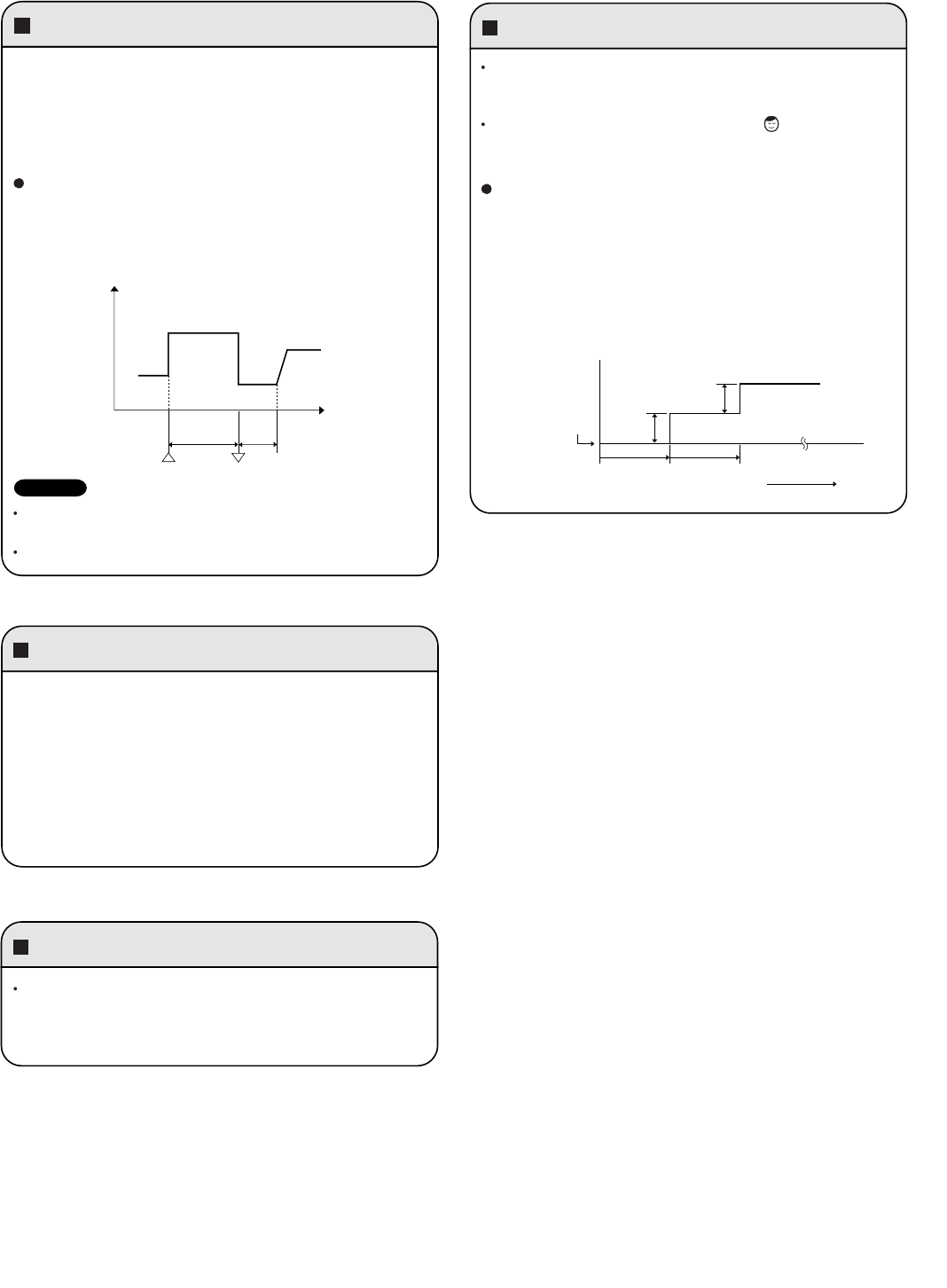
a.
Area: Automatic capacity control
b.
When the temperature drops below Point A, the operation
frequency is reduced by a certain proportion.
c.
Area: Frequency increase is prohibited.
d.
When the temperature reaches Point C or above, freezing
prevention is ended and control is the same as in the
a
area.
*When the temperature drops to below 36°F(2°C)
(continuously for 2 minutes or longer), the compressor stops.
Once the freeze condition is detected, the air conditioner will
work less than the maximum frequency until it is turned off.
The Freeze Prevention Control during the Low Ambient Cooling
Mode (outside air temperature:59
°F(
15
°C)
or lower) is as follows.
The compressor stops when the temperature of indoor heat
exchanger becomes less than 36°F(2°C).
The compressor restarts when the temperature of indoor heat
exchanger becomes 46°F(8°C) or higher.
NOTE
Compressor discharge temperature control
Freeze prevention
During COOL or DRY operation, freezing is detected and
operation is stopped when the temperature of the indoor heat
exchanger matches the conditions below.
1.
Freeze-prevention operation is engaged when the
temperature of the indoor heat exchanger is below 43°F(6°C).
2.
Restart after freeze-prevention operation occurs when the
temperature of the indoor heat exchanger reaches 46°F(8°C)
or above.
A
*
B
C
abcd
Indoor heat exchanger
temperature °F(°C)
36
(2)
43
(6)
46
(8)
This function controls the operation frequency to prevent the
compressor discharge temperature from rising more than a
specified temperature.
a.
Area: Automatic capacity control.
b.
When the temperature rises above Point A, the operation
frequency is reduced at a specified rate.
c.
Area: Further frequency increase is prohibited.
d.
When the temperature falls below Point B, prevention of a rise
in frequency is released and the air conditioner operates as in
a
area.
*The compressor will stop if the temperature of the compressor
discharge exceeds 248°F(120°C) due to shortage of gas or
other reason.
Approx.
214
(101)
A
B
abcd
Compressor discharge temperature °F(°C)
Approx.
201
(94)
8-2. Protective Functions
This function prevents the circuit breaker or fuse from operating
to open the circuit. This function works when electrical current
has increased due to an increase in the cooling load,
or to a decrease in the power supply voltage. In these cases,
operation frequency is reduced or operation is interrupted auto-
matically to control the electrical current for operation.
When the cause of the increase in electrical current is rectified,
the system will resume operation in the original mode.
Peak current cut-off trips 22.5
Hz down 14.0
(A)
CT (Peak current cut-off control)
Cooling Dry
(CLxx models only)
39
1HR.
TIMER
button
ON/OFF
operation
button
ACL
(Reset)
button
ION
button
< Clock display >
Test run mode
Self-diagnostics mode
9. TROUBLESHOOTING
9-1. Precautions before Performing Inspection or Repair
NOTE
After checking the self-diagnostics monitor, turn the power OFF before starting inspection or repair.
High-capacity electrolytic capacitors are used inside the outdoor unit controller (inverter). They retain an electrical charge
(charging voltage DC 310V) even after the power is turned OFF, and some time is required for the charge to dissipate. Be
careful not to touch any electrified parts before the controller LED (red) turns OFF.
If the outdoor controller is normal, approximately 30 seconds will be required for the charge to dissipate. However, allow
at least 5 minutes for the charge to dissipate if there is thought to be any trouble with the outdoor controller.
1:If the operation lamp blinks every 0.5 seconds immediately when the
power is turned ON, there is an external ROM (OTP data) failure on the
indoor circuit board, or a ROM socket insertion problem, or the ROM
has not been installed.
2:The failure mode is stored in memory even when the power is not ON.
Follow the procedure below to perform diagnostics.
9-2. Method of Self-Diagnostics
Follow the procedure below to perform detailed trouble diagnostics.
PROCEDURE
Step 1: Press and hold the remote controller ION button and 1 HR TIMER
button. Then, press and hold the ACL (reset) button with a pointed
object such as the tip of a pen. After 5 seconds, release ACL
button first, then release ION and 1 HR TIMER buttons, "oP-1"
(test run) appears, blinking in the remote controller clock display
area.
Step 2: Next, press the 1 HR TIMER button once to change the display
from "oP-1" to "oP-3" (self-diagnostics). (The display continues to
blink.)
Step 3: Finally press the ON/OFF button to engage self-diagnostics mode.
• The self-diagnostics function utilizes the 3 indicator lamps on the main
unit, in combinations of ON lamps, blinking lamps, and OFF lamps, to
report the existence of sensor trouble or a protective operation. (The
lamps blink or remain ON for 5 seconds, then turn OFF for 2 seconds.)
Self-diagnostics is completed when the buzzer sounds 3 short beeps.
• A maximum of 3 self-diagnostics reports are displayed, for 5 seconds
each, beginning with the most recent report. Following this display the
lamps turn OFF. In order to view the self-diagnostics results again,
press the ON/OFF button again.
• The 3 lamps remain OFF if no trouble has occurred.
<IMPORTANT> After self-diagnostics is completed, be sure to press the
ACL (reset) button to return to normal mode. The air
conditioner will not operate if this is not done.
After turning on power to the air conditioner, use the remote controller and
follow the steps below to execute self-diagnostics.
40
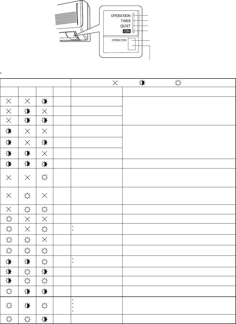
Since the indications cover various units, the corresponding parts listed below may not be present in some models.
REMOTE CONTROL receiver
(1) OPERATION lamp
(2) TIMER lamp
(3) QUIET lamp
ION lamp
OPERATION button
INDOOR UNIT
(1) Self-diagnostics Lamps
Indication on indoor unit .... OFF
Timer Operation Code Diagnostics itemsDiagnostics contents
S01
Room temperature sensor failure
Indoor heat exchanger sensor failure
Humidity sensor failure
Compressor temperature sensor failure
Outdoor heat exchanger sensor failure
Outdoor air temperature sensor failure
Indoor/outdoor communications failure
(serial communications)
Outdoor unit external ROM (OTP data)
failure
Peak current cut-off
• HIC circuit failure
• Power Tr (transistor) circuit failure
PAM circuit failure
Active circuit failure
Outdoor system communications failure
OLR operation
Outdoor power supply open phase
Outdoor coil freezing
Compressor discharge overheat
prevention activated.
Indoor fan operating failure
No-refrigerant protection
DC compressor drive circuit failure
Outdoor fan operating failure
Freeze-prevention operation activated.
4-way valve switching failure
Indoor zero-cross failure
Outdoor electrical current detection
failure
S02
S03
S04
S05
S06
S07
E01
E02
E03
E04
E05
E06
E07
E08
E09
E10
E11
E12
E13
.... Blinking .... ON (Illuminated)
Quiet
(3)(2) (1)
(1)Sensor open circuit or short circuit
(2)Contact failure at connector or open circuit at terminal crimping location
(short-circuit detection only for the humidity sensor)
(3)Indoor/outdoor PCboard failure
(1)Sensor open circuit or short circuit
(2)Contact failure at connector or open circuit at terminal crimping location
(3)Outdoor PCboard failure
Outdoor PCboard failure
(1) Mis-wiring (2) AC power failure (3) Blown fuse (4) Power Relay failure
(5) Indoor or outdoor PCboard failure (6) Outdoor Fan Motor failure (7) Reactor failure
(8) High-Pressure Switch failure (9) Overload Relay failure (10) Magnetic Coil failure
* See detailed flowchart in this section.
(1) HIC or power Tr failure (2) Outdoor fan does not turn. (3) Instantaneous power outage
(4) Service valve not opened. (5) Outdoor fan blocked. (6) Continuous overload operation
(7) Compressor failure (8) Outdoor PCboard failure
(1) External ROM data failure (2) Outdoor PCboard failure
(1) Instantaneous power outage (2) HIC or power transistor failure
(3) Outdoor PCboard failure
(1) Outdoor PCboard failure (2) Outdoor power supply voltage failure
(1) Electric expansion valve failure (2) Capillaries choked (3) Shortage of refrigerant
(4) Continuous overload operation (5) Outdoor fan does not rotate (6) Outdoor
PCboard
failure
(1) Fan motor failure (2) Contact failure at connector (3) Indoor PCboard failure
(1) 4-way valve failure (heat pump model only)
(2) Outdoor PCboard failure
(1) Service valve not opened. (2) Shortage of refrigerant
(1) Open phase (2) Outdoor PCboard failure
(1) Fan motor failure (2) Contact failure at connector (3) Outdoor PCboard failure
(1) Mis-wiring (2) Blown fuse (3) Power Relay failure (4) Outdoor PCboard failure
(5) Compressor failure
* See detailed flowchart in this section.
(1) Indoor fan system failure (2) Shortage of refrigerant (3) Low-temperature operation
41
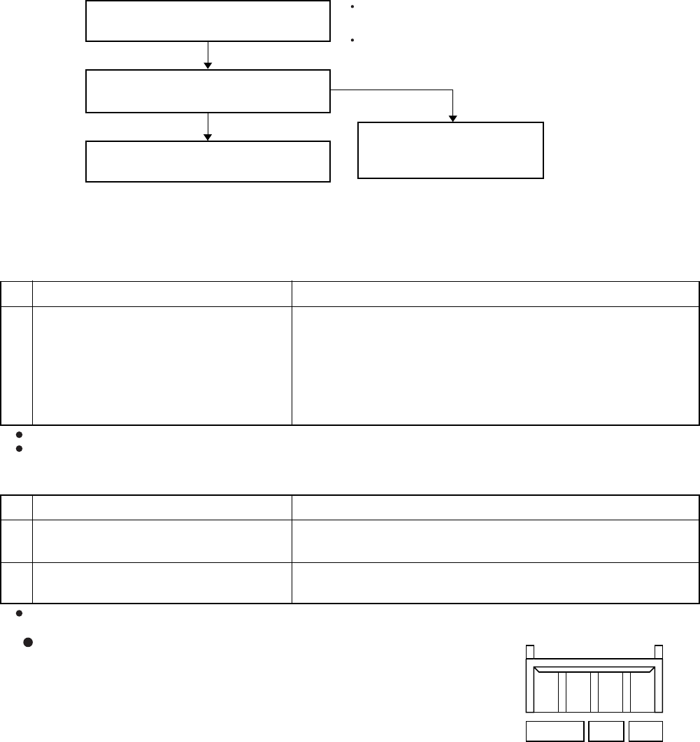
(2) If the self-diagnostics function fails to operate
Check the indoor unit.
Is the fuse blown?
Replace the controller.
Replace the circuit
board or the fuse.
No indicators illuminate and the
indoor fan does not rotate.
Check the power voltage.
Normal
Blown
9-3. Checking the Indoor and Outdoor Units
(1) Checking the indoor unit
(2) Checking the outdoor unit
Using the TEST/T-RUN terminals
ControlNo. Check items (unit operation)
T-RUN :Test run (compressor and fan motor turn ON).
TEST/MV : Compresses time to 1/60th (accelerates
operation by 60 times faster than normal).
Use the remote controller to operate the
unit in "TEST run" mode. To determine
whether the mode is currently in
"TEST run" mode, check the 4 indicator
lamps on the unit. If all 4 are blinking,
the current mode is "TEST run."
If there are no problems with the above, then check the outdoor unit.
1The rated voltage must be present between inter-unit wirings 1 and 2.
Connect a 5 k ohm resistor between inter-unit wirings 2 and 3. When the
voltage at both ends is measured, approximately 12 to 15V DC must
be output and the multimeter pointer must bounce once every 8
seconds.
Or instead of measuring the voltage, you can insert an LED jig and
check that the LED flickers once every 8 seconds.
•
•
ControlNo. Check items (unit operation)
Apply the rated voltage between outdoor
unit terminals L and N.
If there are no problems with the above, then check the indoor unit.
1 The control panel LED (red) must illuminate.
Short-circuit the outdoor unit COM terminal
to the T-RUN terminal.
2 The compressor and fan motor must all turn on.
•
•
TEST/T-RUN terminals
(TEST)/MV T-RUN COM
For the "Test run" procedure, refer to the Appendix B "Installation Instructions".
42
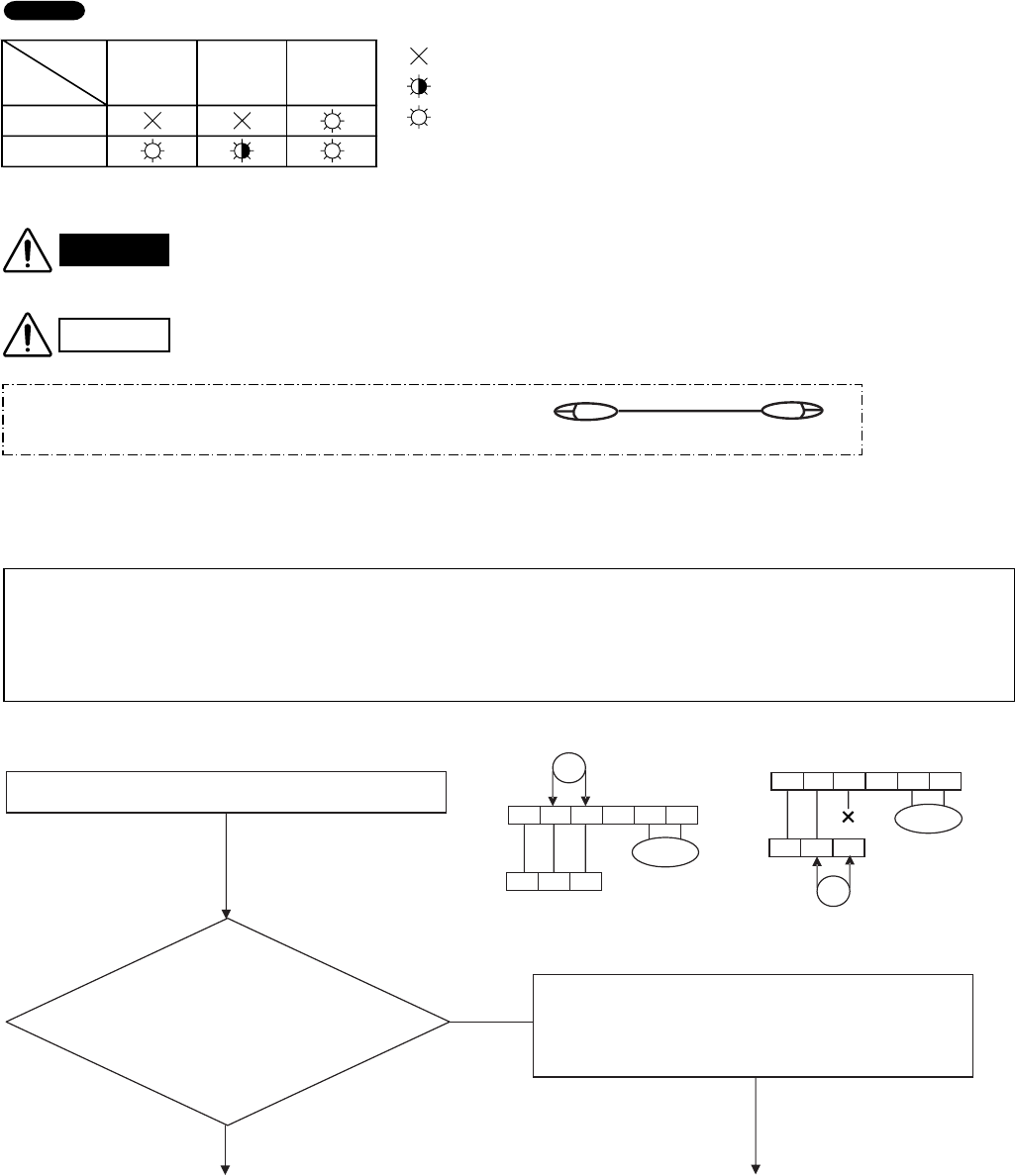
(3) Serial Communication Error Identification Procedure
Refer to "Method of Self-Diagnostics" for the self-diagnostics procedure.
(3-1) Condition: E01
< Before the Operation >
If the lamps on the main body show the following conditions after the completion of self-diagnostics,
a communication error between the indoor unit and outdoor unit might be considered.
In such a case, identify the breakdown section by using the following procedure.
Troubleshooting Serial Communication
Is the voltage of about DC12V
or more given between the terminals
2 and 3 on the outdoor unit terminal strip
(Serial Communication Line) ?
(Fig. 1)
No
Yes
1.Turn OFF the power and wait until the power lamp (LED)
of the outdoor unit controller is turned OFF.
2.Disconnect the cable from the terminal 3 on the indoor unit
terminal strip. (Fig. 2)
3.Turn ON the power.
< Convenient Tool for Short-Circuit Work ( for example ) >
Alligator Clip
Alligator Clip Cable
A
( Continued to the next page A. )
B
( Continued to the next page B. )
For terminal strip short circuit work or inter-unit wiring removal, turn off the power to
avoid an electric shock.
Release the terminal strip short circuit after the completion of self-diagnostics.
Do not perform the short-circuit work between any other terminals except for
specified ones on the specified terminal strip. If such work is performed between
the incorrect terminals, the unit might be broken.
Fig. 1
Outdoor Unit
Power
1 2 43 5 6
1 2 3
V
+-
Indoor Unit
Outdoor Unit
1 2 43 5 6
1 2 3
V
+
-
Power
Indoor Unit
Fig. 2
NOTE
Lamp
Quiet
Timer Operation :Off
: Blinking
Condition (3) (2) (1)
: Illuminated
E01
E12
CAUTION
WARNING
< Check Items before Troubleshooting Serial Communication Start >
After confirming that the following errors do not exist, start the "Troubleshooting Serial Communication"
in "Condition: E01 and E12".
1.Mis -wiring (inter-unit cable, etc.)
2.AC power failure
3.Blown fuse
4.Power Relay failure
5.Outdoor Fan Motor failure (defective insulation, etc.)
6.Reactor failure (defective insulation, etc.)
7.High-Pressure Switch failure
8.Overload Relay failure
9.Magnetic Coil failure (defective insulation, short-circuit, etc.)
10.Compressor failure (defective insulation, etc.)
43
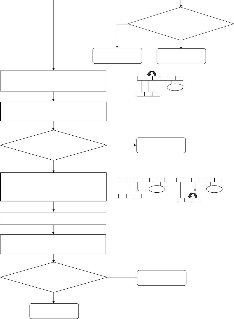
What is the latest self-diagnosis result ?
Condition: E12 Defect in the outdoor unit
P. C. board.
Condition: E01
Defect or connection error
in the inter-unit cable
Defect in the indoor unit
P.C. board
( Continued from the previous page A. )
A
( Continued from the previous page B. )
B
1 2 43 5 6
1 2 3
Outdoor Unit
Power
Fig. 3
Indoor Unit
1 2 43 5 6
1 2 3
Outdoor Unit
Power
Fig. 4
Indoor Unit
1 2 43 5 6
1 2 3
Outdoor Unit
Power
Fig. 5
Indoor Unit
Condition: E12
Condition: E01
1.Turn OFF the power and wait until the power lamp (LED)
of the outdoor unit controller is turned OFF.
2.Short-circuit between the terminals 2 and 3 on the outdoor
unit terminal strip. (Fig. 3)
1.Turn ON the power and operate the system using the
remote controller or the operation button on the indoor unit.
2.Perform the self-diagnosis five seconds after the operation
start.
1.Turn off the power and wait until the power lamp (LED)
of the outdoor unit controller is turned OFF.
2.Remove the short-circuit between the terminals 2 and 3 on
the outdoor unit terminal strip.
3.Disconnect the cable from the terminal 3 on the indoor unit
terminal strip. (Fig. 4)
Short-circuit between the terminals 2 and 3 on the indoor unit
terminal board. (Fig. 5)
1.Turn ON the power and operate the system using the
remote controller or the operation button on the indoor unit.
2.Perform the self-diagnosis five seconds after the operation
start.
What is the latest self-diagnosis result ?
Defect in the indoor unit
P.C. board
Is the voltage of about DC22V to
24V given between the terminals
2 and 3 on the indoor unit terminal strip
(Serial Communication Line) ?
(Fig. 2)
No
Defect or connection error
in the inter-unit cable
Yes
44
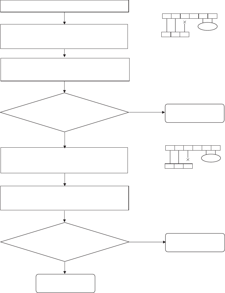
(3-2) Condition: E12
Troubleshooting Serial Communication
1.Turn off the power and wait until the power lamp (LED)
of the outdoor unit controller is turned OFF.
2.Disconnect the cable from the terminal 3 on the indoor
unit terminal strip. (Fig. 7)
Defect in the indoor unit
P.C. board
Defect in the outdoor unit
P.C. board
1.Turn ON the power and operate the system using the
remote controller or the operation button on the indoor unit.
2.Perform the self-diagnosis five seconds after the operation
start.
1.Turn off the power and wait until the power lamp (LED)
of the outdoor unit controller is turned OFF.
2.Disconnect the cable from the terminal 3 on the Outdoor
unit terminal strip. (Fig. 6)
Defect in the inter-unit
cable
1.Turn ON the power and operate the system using the
remote controller or the operation button on the indoor unit.
2.Perform the self-diagnosis five seconds after the operation
start.
Condition: E12
Condition: E01
Condition: E01
Condition: E12
What is the latest self-diagnosis result ?
What is the latest self-diagnosis result ?
1 2 43 5 6
1 2 3
Outdoor Unit
Fig. 6
Power
Indoor Unit
1 2 43 5 6
123
Power
Fig. 7
Outdoor Unit
Indoor Unit
45
9-4. Trouble Diagnosis of Fan Motor
9-4-1. Outdoor Fan Motor
This outdoor DC fan motor contains an internal control PCB. Therefore, it is not possible to measure the coil
resistance, and the following procedure should be used to check the motor.
Perform the trouble diagnosis by Test Run mode described on Installation Instructions.
[Trouble symptom 1]The fan does not stop when the outdoor unit stops. Outdoor unit controller trouble
[Trouble symptom 2]The fan motor does not rotate when the outdoor unit is operating.
(Diagnostic procedure)
* Disconnect the motor connectors and measure the voltage at the DC motor connectors on the outdoor
unit controller (3 locations).
(Diagnostic results)
All of the above measured values are normal. Fan motor trouble (Replace the motor.)
Any one of the above measured values is not normal. Outdoor unit controller trouble
(Replace the controller .)
(Reference)DC motor connector pin arrangement
Pin 1: Vs (white)
Pin 2: Not used
Pin 3: Not used
Pin 4: Gnd (black)
Pin 5: Vcc (red)
Pin 6: FG (blue)
Pin 7: Vsp (yellow)
[Trouble symptom 3]Motor rotates for some time (several seconds), but then quickly stops, when the outdoor
unit operates.
(There is trouble in the system that provides feedback of motor rotation speed from the
motor to the outdoor unit controller.)
[Trouble symptom 4]Fan motor rotation speed does not change during outdoor unit operation.
[Trouble symptom 5]Fan motor rotation speed varies excessively during outdoor unit operation.
(Remedy for symptom 3 to 5)
It is not possible to identify whether the trouble is outdoor unit controller trouble or motor trouble.
Therefore, first replace the outdoor unit controller, then (if necessary) replace the DC motor.
Important: (A) Turn OFF the power before connecting or disconnecting the motor connectors.
(B) When performing voltage measurement at the outdoor controller connector for (3) in the table
below, the DC motor will trip and voltage output will stop approximately 10 seconds after
operation is started. For this reason, to measure the voltage again, first turn OFF the outdoor
unit power, then, measure the voltage in Test Run mode.
(1) Vs-Gnd: Between pin 1 and pin 4
(2) Vcc-Gnd: Between pin 5 and pin 4
(3) Vsp-Gnd: Between pin 7 and pin 4
Measurement location
DC 110V or more
DC 14V or more
After fluctuating 4 times between DC 1.0 to 4.3V
(1 sec. ON) and DC 0 V (1 sec. OFF), the DC
motor trips.
Normal value
46

9-5. Noise Malfunction and Electromagnetic Interference
An inverter A/C operates using pulse signal control and high frequencies. Therefore, it is susceptible to the effects of external
noise, and is likely to cause electromagnetic interference with nearby wireless devices.
A noise filter is installed for ordinary use, preventing these problems. However, depending on the installation conditions, these
effects may still occur. Please pay attention to the points listed below.
(1) Noise malfunction
This refers to the application of high-frequency noise to the signal wires, resulting in abnormal signal pulses and malfunction.
Locations most susceptible to noise
1.Locations near broadcast stations where
there are strong electromagnetic waves
2.Locations near amateur radio (short wave)
stations
3.Locations near electronic sewing machines
and arc-welding machines
Correction
(The fundamental concept is to make the
system less susceptible to noise.)
- Insulate for noise or
distance from the noise source. -
1.Use shielded wires.
2.Move unit away from the noise source.
Trouble
Either of the following trouble may occur.
1.The unit may stop suddenly during
operation.
2.Indicator lamps may flicker.
(2) Electromagnetic interference
This refers to noise generated by high-speed switching of the microcomputer and compressor. This noise radiates through
space and returns to the electric wiring, affecting any wireless devices (televisions, radios, etc.) located nearby.
Locations most susceptible to noise
1.A television or radio is located near the
A/C and A/C wiring.
2.The antenna cable for a television or
radio is located close to the A/C and A/C
wiring.
3.Locations where television and radio
signals are weak.
Correction
1.Select a separate power source.
2.Keep the A/C and A/C wiring at least 1 meter
away from wireless devices and antenna cables.
3.Change the wireless device’s antenna to a high-
sensitivity antenna.
4.Change the antenna cable to a BS coaxial cable.
5.Use a noise filter (for the wireless device).
6.Use a signal booster.
Trouble
1.Noise appears in the television picture,
or the picture is distorted.
2.Static occurs in the radio sound.
47
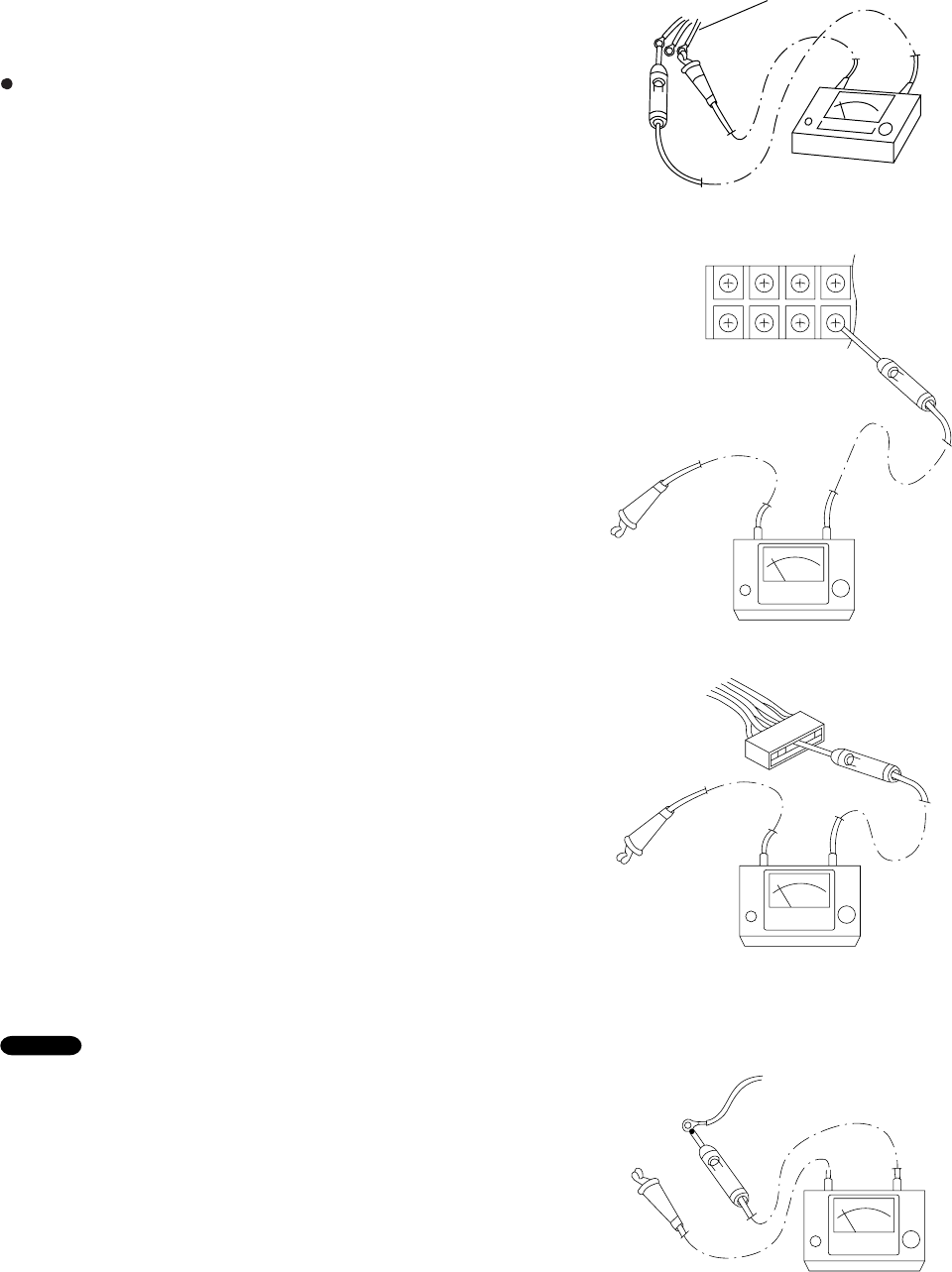
Insulation
tester
Probe
Clip
Ground wire
Terminal plate
Copper
tube or
metallic part
Clip
Insulation
tester
Probe
Fig. 1
Fig. 2
Fig. 3
Fig. 4
Copper
tube or
metallic part
Clip
Insulation
tester
Probe
Clip
Insulation
tester
Probe
Metallic
part
From fan motor,
compressor and
other parts
10. CHECKING ELECTRICAL COMPONENTS
10-1. Measurement of Insulation
Resistance
The insulation is in good condition if the resistance
exceeds 1M ohm.
10-1-1. Power Supply Cord
Clamp the grounding wire of power cord with the lead
clip of the insulation resistance tester and measure the
resistance by placing a probe on either of the two
power wires. (Fig. 1)
Then also measure the resistance between the
grounding and other power terminals. (Fig. 1)
10-1-2. Indoor Unit
Clamp an aluminum plate fin or copper tube with the
lead clip of the insulation resistance tester and
measure the resistance by placing a probe on each
terminal screw on the terminal plate. (Fig. 2)
Note that the ground line terminal should be skipped
for the check.
10-1-3. Outdoor Unit
Clamp a metallic part of the unit with the lead clip of
the insulation resistance tester and measure the
resistance by placing a probe on each terminal screw
where power supply lines are connected on the
terminal plate. (Fig. 2)
10-1-4. Measurement of Insulation
Resistance for Electrical Parts
Disconnect the lead wires of the desired electric part
from terminal plate, capacitor, etc. Similarly disconnect
the connector. Then measure the insulation resistance.
(Figs. 3 and 4)
Refer to Electric Wiring Diagram.
If the probe cannot enter the poles because the hole is
too narrow then use a probe with a thinner pin.
NOTE
48
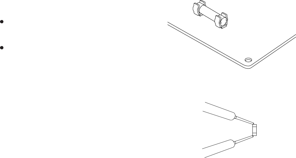
Fuse
PCB Ass'y
Fig. 5
Fig. 6
Fuse
10-2. Checking Continuity of Fuse
on PCB Ass'y
Remove the PCB Ass'y from the electrical
component box. Then pull out the fuse from the PCB
Ass'y. (Fig. 5)
Check for continuity using a multimeter as shown in
Fig. 6.
49

11. REFRIGERANT R410A:
SPECIAL PRECAUTIONS WHEN SERVICING UNIT
11-1. Characteristics of New Refrigerant R410A
11-1-1. What is New Refrigerant R410A?
R410A is a new refrigerant that contains two types of pseudo-non-azeotropic refrigerant mixture. Its
refrigeration capacity and energy efficiency are about the same level as the conventional refrigerant, R22.
11-1-2. Components (mixing proportions)
HFC32 (50%) / HFC125 (50%)
11-1-3. Characteristics
Less toxic, more chemically stable refrigerant
The composition of refrigerant R410A changes whether it is in a gaseous phase or liquid phase. Thus, when
there is a refrigerant leak the basic performance of the air conditioner may be degraded because of a change in
composition of the remaining refrigerant. Therefore, do not add new refrigerant. Instead, recover the
remaining refrigerant with the refrigerant recovery unit. Then, after evacuation, totally recharge the specified
amount of refrigerant with the new refrigerant at its normal mixed composition state (in liquid phase).
When refrigerant R410A is used, the composition will differ depending on whether it is in gaseous or liquid
phase, and the basic performance of the air conditioner will be degraded if it is charged while the refrigerant is in
gaseous state. Thus, always charge the refrigerant while it is in liquid phase.
Ether-type oil is used for compressor oil for R410A-type units, which is different
from the mineral oil used for R22. Thus more attention to moisture prevention and
faster replacement work compared with conventional models are required.
CAUTION
50
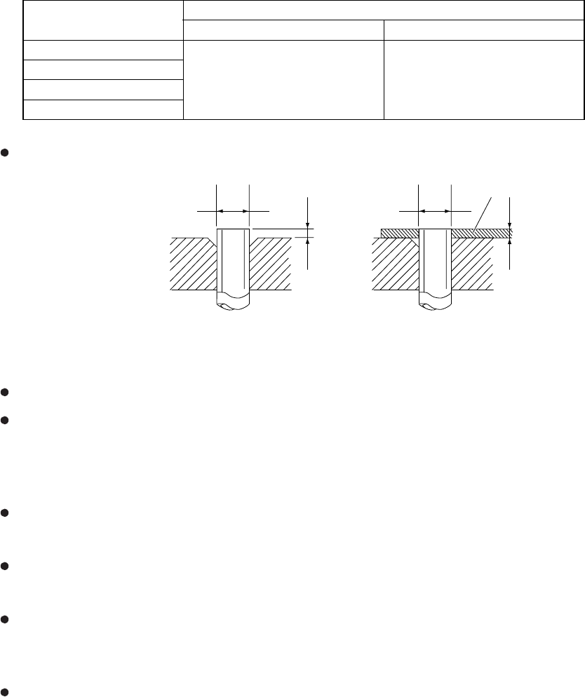
Tubing precautions
Refrigerant R410A is more easily affected by dust or moisture compared with R22, thus be sure to temporarily
cover the ends of the tubing with caps or tape prior to installation.
Never use 0.0276" (0.7 mm)-thick copper tubing or tubing which is less than 0.0315" (0.8 mm) in thickness, since
air conditioners with R410A are subject to higher pressure than those using R22 and R407C.
No addition of compressor oil for R410A
No additional charge of compressor oil is permitted.
No use of refrigerant other than R410A
Never use a refrigerant other than R410A.
If refrigerant R410A is exposed to fire
Through welding, etc., toxic gas may be released when R410A refrigerant is exposed to fire. Therefore, be sure
to provide ample ventilation during installation work.
Caution in case of R410A leak
Check for possible leak points with the special leak detector for R410A. If a leak occurs inside the room,
immediately provide thorough ventilation.
A
D
Flare tool for R410A
A
D
Conventional flare tool (R22)
Spacer
11-2. Checklist before Servicing
Use a clutch-type flare tool for R410A or the conventional flare tool. Note that sizes of the resultant flares differ
between these two tools. Where a conventional flare tool is used, make sure to observe A Specification (amount of
extrusion) by using the flare spacer.
Size of flare
Specification A
Diameter of tube D
Dia.1/4" (6.35 mm)
Dia.3/8" (9.52 mm)
Dia.1/2" (12.7 mm)
Dia.5/8" (15.88 mm)
Flare tool for R410A Conventional flare tool (for R22)
0 to 0.0196"
(0 to 0.5 mm)
0.0472"
(1.2 mm)
51
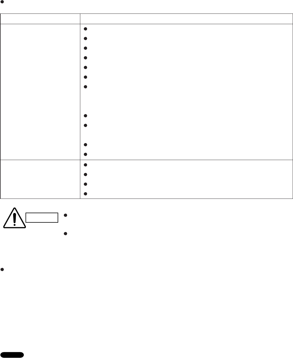
11-3. Tools Specifically for R410A
For servicing, use the following tools for R410A
Gauge manifold
Charging hose
Gas leak detector
Refrigerant cylinder
Charging cylinder
Refrigerant recovery unit
Vacuum pump with anti-reverse flow (*1)
(Solenoid valve-installed type, which prevents oil from flowing back into the
unit when the power is off, is recommended.)
Vacuum pump (*2)...can be used if the following adapter is attached.
Vacuum pump adapter (reverse-flow prevention adapter) (*3).
(Solenoid valve-installed adapter attached to a conventional vacuum pump.)
Electronic scale for charging refrigerant
Flare tool
Bender
Torque wrench
Cutter, reamer
Welding tool, nitrogen gas cylinder
Tools specifically for R410A
Tool Distinction Tool Name
Tools which can be com-
monly used for R22,
R407C, and R410A
CAUTION The above tools specifically for R410A must not be used for R22 and R407C.
Doing so will cause malfunction of the unit.
For the above vacuum pump (*1, *2) and vacuum pump adapter (*3), those for
R22-type units can be used for R410A-type. However, they must be used
exclusively for R410A and never alternately with R22 and R407C.
For details on tubing installation procedures, refer to the installation manuals attached to the indoor
unit and outdoor unit.
To prevent other refrigerants (R22, R407C) from being mistakenly charged to this unit, shape and external
diameter of the service port screw has been altered.
<External diameter of service port> R410A : 5/16"
R22, R407C : 1/4"
11-4. Tubing Installation Procedures
When the tubes are connected, always apply HAB oil on the flare portions to improve the sealing of tubing.
The following is the HAB oil generally used:
Esso: ZERICE S32
NOTE
52
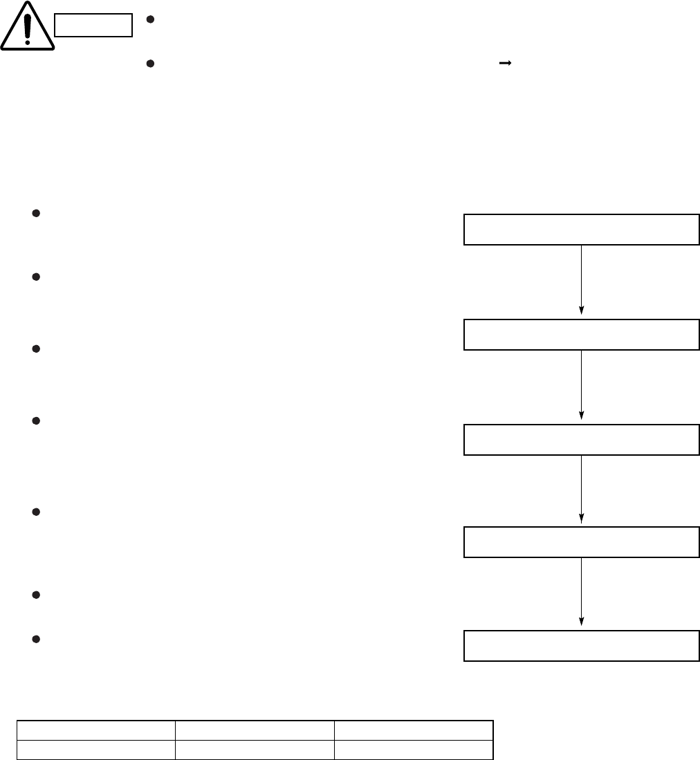
11-5. In Case of Compressor Malfunction
CAUTION Should the compressor malfunction, be sure to make the switch to a replacement
compressor as quickly as possible.
Use only the tools indicated exclusively for R410A. See "11-3. Tools
Specifically for R410A."
11-5-1. Procedure for Replacing Compressor
(1) Recovering refrigerant
Any remaining refrigerant inside the unit should not be
released to the atmosphere, but recovered using the
refrigerant recovery unit for R410A.
Do not reuse the recovered refrigerant, since it will contain
impurities.
(2) Replacing Compressor
Soon after removing seals of both discharge and suction
tubes of the new compressor, replace it quickly.
(3) Checking for sealing
Use nitrogen gas for the pressurized gas, and never use a
refrigerant other than R410A. Also do not use oxygen or
any flammable gas.
(4) Evacuation
Use a solenoid valve-installed vacuum pump so that
even if power is cut off in the middle of evacuation of air
due to a power interruption, the valve will prevent the
pump oil from flowing back.
The equipment may be damaged if moisture remains in
the tubing, thus carry out the evacuation thoroughly.
When using a vacuum pump with exhaust air volume more
than 0.883 cu.ft./min. and ultimate vacuum pressure rate
of 50 micron Hg.
Standard time for evacuation
(1) Recover refrigerant
OK
(2) Replace compressor
OK
(3) Check for sealing
OK
(4) Evacuation
OK
(5) Recharge
Length of tubing
Evacuation time
Less than 33 ft. (10 m)
More than 10 minutes
More than 33 ft. (10 m)
More than 15 minutes
53
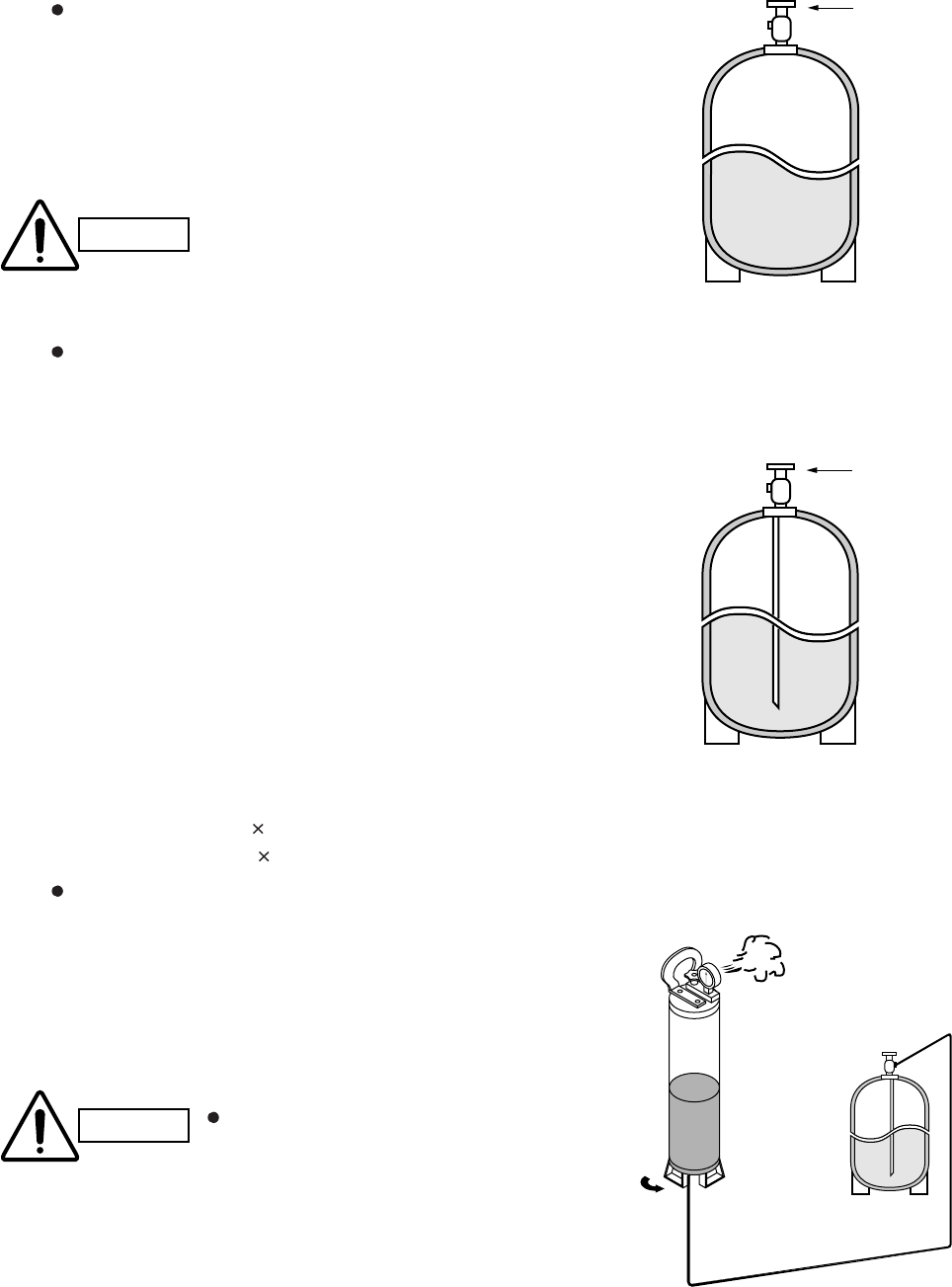
Valve
Single valve
Charge liquid refrigerant with
cylinder in up-side-down position.
Single valve (with siphon tube)
Charge with cylinder in normal position.
Liquid
Valve
Liquid
Charging
cylinder
Open Refrigerant
cylinder
Liquid
NO!
CAUTION Never charge a large amount
of liquid refrigerant at once to
the unit. This may cause
damage to the compressor.
CAUTION To prevent the composition
of R410A from changing,
never bleed the refrigerant
gas into the atmosphere
while transferring the
refrigerant. (Fig. 3)
(5) Recharging
Be sure to charge the specified amount of
refrigerant in liquid state using the service port
of the wide tube service valve. The proper
amount is listed on the unit's nameplate.
When the entire amount cannot be charged all at
once, charge gradually while operating the unit in
Cooling Operation.
When charging with a refrigerant cylinder, use an
electronic scale for charging refrigerant. In this
case, if the volume of refrigerant in the cylinder
becomes less than 20% of the fully-charged
amount, the composition of the refrigerant starts
to change. Thus, do not use the refrigerant if
the amount in the charging cylinder is less
than 20%.
Also, charge the minimum necessary amount to
the charging cylinder before using it to charge
the air conditioning unit.
Example:
In case of charging refrigerant to a unit requiring
1.68 lb. (0.76 Kg) using a capacity of a 22 lb. (10
Kg) cylinder, the minimum necessary amount for
the cylinder is:
1.68 + 22 0.20 = 6.08 lb.
(0.76 + 10 0.20 = 2.76 Kg)
For the remaining refrigerant, refer to the
instructions of the refrigerant manufacturer.
If using a charging cylinder, transfer the specified
amount of liquid refrigerant from the refrigerant
cylinder to the charging cylinder.
Prepare an evacuated charging cylinder
beforehand.
Do not use the refrigerant if the amount in the
charging cylinder is less than 20%.
Configuration and characteristics of cylinders
Fig. 1
Fig. 2
Fig. 3
54
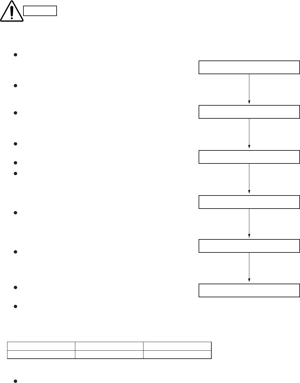
Length of tubing
Evacuation time
Less than 33 ft. (10 m)
More than 10 minutes
More than 33 ft. (10 m)
More than 15 minutes
11-6. In Case Refrigerant is Leaking
CAUTION Never attempt to charge additional refrigerant when refrigerant has been leaking
from the unit. Follow the procedure described below to locate points of leaks and
carry out repairs, then recharge the refrigerant.
(1) Detecting Leaks
Use the detector for R410A to locate refrigerant leak
points.
(2) Recovering refrigerant
Never release the gas to the atmosphere; recover
residual refrigerant using the refrigerant recovery unit for
R410A, instead.
Do not reuse the recovered refrigerant because its
composition will have been altered.
(3) Welding leaking points
Confirm again that no residual refrigerant exists in the unit
before starting welding.
Weld securely using flux and wax for R410A.
Prevent oxide film from forming inside the tubes utilizing
substitution with nitrogen (N2) in the refrigerant circuit of
the unit. Leave ends of tubes open during welding.
(4) Checking for sealing
Use nitrogen gas for the pressurized gas, and never use
a refrigerant other than R410A. Also do not use oxygen or
any flammable gas.
(5) Evacuation
Use a solenoid valve-installed vacuum pump so that
even if power is cut off in the middle of evacuation of air
due to a power interruption, the valve will prevent the
pump oil from flowing back.
The equipment may be damaged if moisture remains in
the tubing, thus carry out the evacuation thoroughly.
When using a vacuum pump with exhaust air volume
more than 0.883 cu.ft./min. and ultimate vacuum pressure
rate of 50 micron Hg.
Standard time for evacuation
(6) Recharging
Recharge unit in the same manner explained on the
previous page "(5) Recharging."
(2) Recover refrigerant
OK
(3) Weld leaking points
OK
(4) Check for sealing
OK
(5) Evacuation
OK
(6) Recharge
(1) Detect leaks
OK
55

11-7. Charging Additional Refrigerant
11-7-1. When Tubes are Extended
Observe the proper amount of refrigerant as stated in this service manual or the installation manual that came
with the indoor unit. Charge additional refrigerant in liquid state only.
11-8. Retro-Fitting Existing Systems
11-8-1. Use of Existing Units
Never use new refrigerant R410A for existing units which use R22. This will cause the air conditioner to
operate improperly and may result in a hazardous condition.
11-8-2. Use of Existing Tubing
If replacing an older unit that used refrigerant R22 with a R410A unit, do not use its existing tubing. Instead,
completely new tubing must be used.
CAUTION Never charge additional refrigerant if refrigerant is leaking from the unit. Follow
instructions given in "11-6. In Case Refrigerant is Leaking" and completely carry
out repairs. Only then should you recharge the refrigerant.
56

INSTRUCTION MANUAL
KS0971+C0971
+CL0971
KS1271+C1271
+CL1271
(OI-852-6-4180-803-00-2)
APPENDIX A
A-1

2
Features
This air conditioner is an inverter type unit that automatically adjusts capacity as appropriate. Details on these functions
are provided below; refer to these descriptions when using the air conditioner.
• Microprocessor Controlled Operation
The interior compartment of the remote control unit
contains several features to facilitate automatic
operation, easy logically displayed for easy use.
• Simple One-touch Wireless Remote Control
The remote control unit has several features to
facilitate automatic operation.
• 24-Hour ON or OFF Timer
This timer can be set to automatically turn the unit
on or off at any time within a 24 hour period.
• 1-Hour OFF Timer
This timer can be set to automatically turn off the
unit at any time after one hour.
• Night Setback
Pressing this button changes the setting of the
room temperature thermostat, allowing you to set
the temperature at whatever level that you find
comfortable.
• Automatic and 3-step Fan Speed
Auto/High/Medium/Low
• Air Sweep Control
This function moves a flap up and down in the air
outlet, directing air in a sweeping motion around the
room and providing comfort in every corner.
• Auto. Flap Control
This automatically sets the flap to the optimum
position during cooling and drying operation.
• Automatic Restart Function for Power Failure
Even when power failure occurs, preset
programmed operation can be reactivated once
power resumes.
• High Power Operation
The unit operates at maximum output for 30
minutes, regardless of the desired temperature.
The fan speed is 1 step above “High”.
• Quiet Operation
The fan rotates slower than the fan speed setting to
provide a quieter operating sound.
• ION Operation
While it is operating, the unit generates negative
ions that freshen up the air in the room.
• Anti-Mold Filter
This unit is equipped with an anti-mold filter that
inhibits the growth of mold and bacteria.
• Air Clean Filter
An air filter that eliminates unpleasant odors and
cleans the air is available.
Purchase a replacement filter at your local dealer.
(model STK-FDXB)
OI-803-2-EG
01_KS0971_En.fm Page 2 Monday, July 9, 2007 3:28 PM
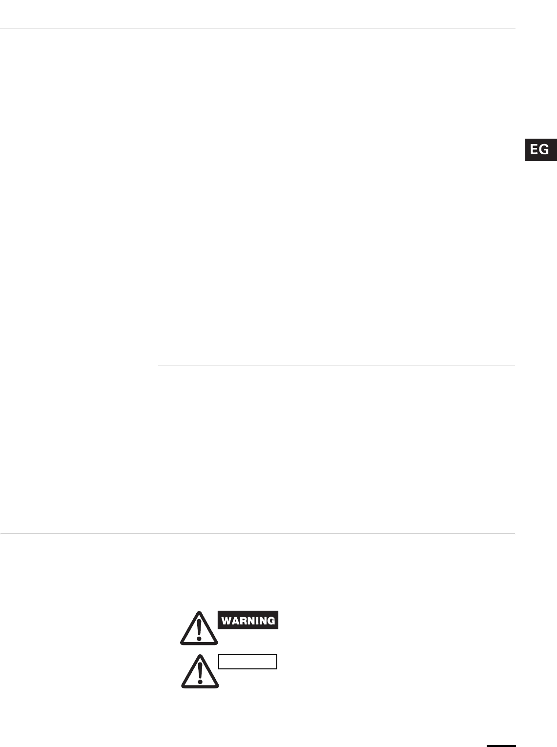
3
Contents
Page
Features............................................................................................................ 2
Product Information........................................................................................... 3
Alert Symbols.................................................................................................... 3
Installation Location .......................................................................................... 4
Electrical Requirements.................................................................................... 4
Safety Instructions............................................................................................. 4
Names of Parts ................................................................................................. 5
Using the Remote Control Unit ....................................................................... 10
Operation with the Remote Control Unit ........................................................ 12
1. Operation ............................................................................................... 12
2. Adjusting the Fan Speed........................................................................ 13
3. Fan Only................................................................................................. 13
4. Night Setback Mode............................................................................... 14
5. QUIET Mode.......................................................................................... 15
6. HIGH POWER Mode ............................................................................. 15
7. ION Mode............................................................................................... 15
Special Remarks............................................................................................. 16
Setting the Timer............................................................................................. 17
Using the 1-Hour OFF Timer .......................................................................... 19
Tips for Energy Saving.................................................................................... 19
Adjusting the Airflow Direction ........................................................................ 20
Operation without the Remote Control Unit .................................................... 21
Care and Cleaning .......................................................................................... 21
Troubleshooting............................................................................................... 24
Operating Range............................................................................................. 24
Product Information
If you have problems or questions concerning your Air Conditioner, you will need
the following information. Model and serial numbers are on the nameplate on the
bottom of the cabinet.
Model No. ______________________ Serial No. ____________________
Date of purchase ________________________________________________
Dealer’s address ________________________________________________
Phone number ________________
Alert Symbols
The following symbols used in this manual, alert you to potentially
dangerous conditions to users, service personnel or the appliance:
This symbol refers to a hazard or unsafe
practice which can result in severe
personal injury or death.
This symbol refers to a hazard or unsafe
practice which can result in personal injury
or product or property damage.
CAUTION
OI-803-3-EG
01_KS0971_En.fm Page 3 Monday, July 9, 2007 3:28 PM
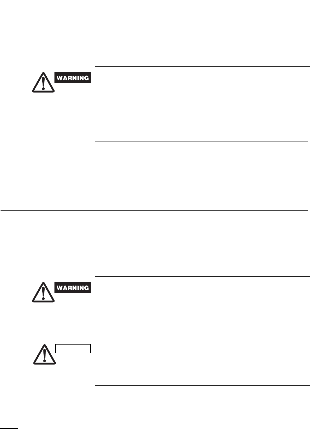
4
Installation Location
• We recommend that this air conditioner be installed properly by qualified
installation technicians in accordance with the Installation Instructions
provided with the unit.
• Before installation, check that the voltage of the electric supply in your home or
office is the same as the voltage shown on the nameplate.
Electrical Requirements
1. All wiring must conform to the local electrical codes. Consult your dealer or a
qualified electrician for details.
2. Each unit must be properly grounded with a ground (or earth) wire or through
the supply wiring.
3. Wiring must be done by a qualified electrician.
Safety Instructions
• Read this Instruction Manual carefully before using this air conditioner. If
you still have any difficulties or problems, consult your dealer for help.
• This air conditioner is designed to give you comfortable room conditions.
Use this only for its intended purpose as described in this Instruction
Manual.
• Do not install this air conditioner where there are fumes or flammable
gases, or in an extremely humid space such as a greenhouse.
• Do not install the air conditioner where excessively high heat-generating
objects are placed.
Avoid: To protect the air conditioner from heavy corrosion, avoid installing the outdoor
unit where salty sea water can splash directly onto it or in sulphurous air near a
spa.
• Never use or store gasoline or other flammable vapor or liquid near the
air conditioner — it is very dangerous.
• This air conditioner has no ventilator for intaking fresh air from
outdoors. You must open doors or windows frequently when you use
gas or oil heating appliances in the same room, which consume a lot of
oxygen from the air. Otherwise there is a risk of suffocation in an
extreme case.
• Do not turn the air conditioner on and off from the power mains switch.
Use the ON/OFF operation button.
• Do not stick anything into the air outlet of the outdoor unit. This is
dangerous because the fan is rotating at high speed.
• Do not let children play with the air conditioner.
• Do not cool the room too much if babies or invalids are present.
CAUTION
OI-803-4-EG
01_KS0971_En.fm Page 4 Monday, July 9, 2007 3:28 PM
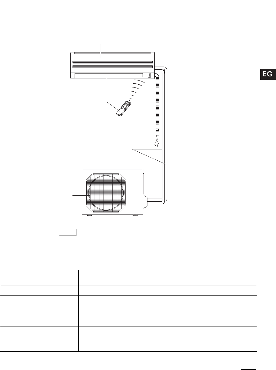
5
Names of Parts
This illustration is based on the external view of a standard model.
Consequently, the shape may differ from that of the air conditioner which you
have selected.
This air conditioner consists of an indoor unit and an outdoor unit. You can control
the air conditioner with the remote control unit.
Air Intake Air from the room is drawn into this section and passes through air filters which
remove dust.
Air Outlet Conditioned air is blown out of the air conditioner through the air outlet.
Remote Control Unit The wireless remote control unit controls power ON/OFF, operation mode
selection, temperature, fan speed, timer setting, and air sweeping.
Refrigerant Tubes The indoor and outdoor units are connected by copper tubes through which
refrigerant gas flows.
Drain Hose Moisture in the room condenses and drains off through this hose.
Outdoor (Condensing) Unit The outdoor unit contains the compressor, fan motor, heat exchanger coil, and
other electrical components.
INDOOR UNIT
Air intakes
Remote control unit
Air outlet
Refrigerant tubes
Drain hose
OUTDOOR UNIT
Air outlet
NOTE
OI-803-5-EG
01_KS0971_En.fm Page 5 Monday, July 9, 2007 3:28 PM
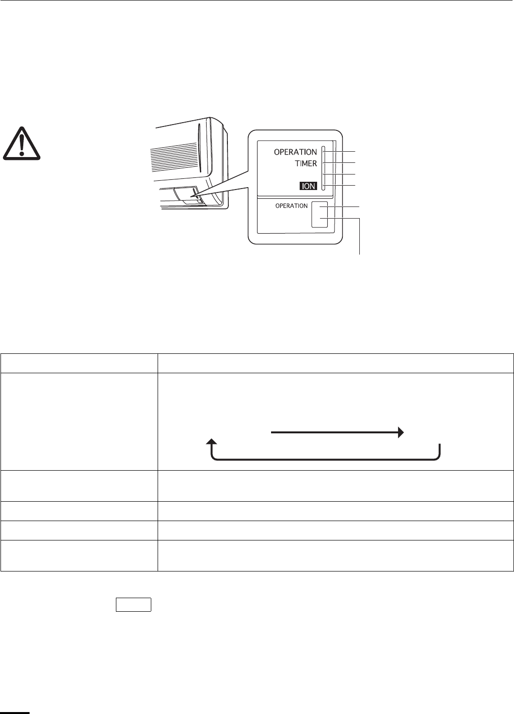
6
Unit Display and Operation Button
REMOTE CONTROL receiver This section picks up infrared signals from the remote control unit (transmitter).
OPERATION button When the remote control cannot be used, pressing this button enables cooling
operation.
Each time this button is pressed, the operation mode changes cyclically.
OPERATION lamp This lamp lights when the system is in the continuous DRY (orange), COOL
(green) and FAN (green) mode.
TIMER lamp This lamp lights when the system is being controlled by the timer.
QUIET lamp This lamp lights during operation in the QUIET mode.
ION lamp This lamp lights during operation in the ION mode while the indoor unit is
operating.
The unit’s display lamps are dimmed during operation in the NIGHT SETBACK
mode.
QUIET
REMOTE CONTROL receiver
Avoid using radio equipment
such as mobile phone near
(within 4 ft.) the remote
control receiver. Some radio
equipment may cause
malfunction of the unit.
If the trouble happens,
disconnect power and restart
the air conditioner after a few
minutes.
IMPORTANT
OPERATION lamp
TIMER lamp
QUIET lamp
OPERATION button
INDOOR UNIT
ION lamp
Cooling operation Stop
NOTE
OI-803-6-EG
01_KS0971_En.fm Page 6 Monday, July 9, 2007 3:28 PM
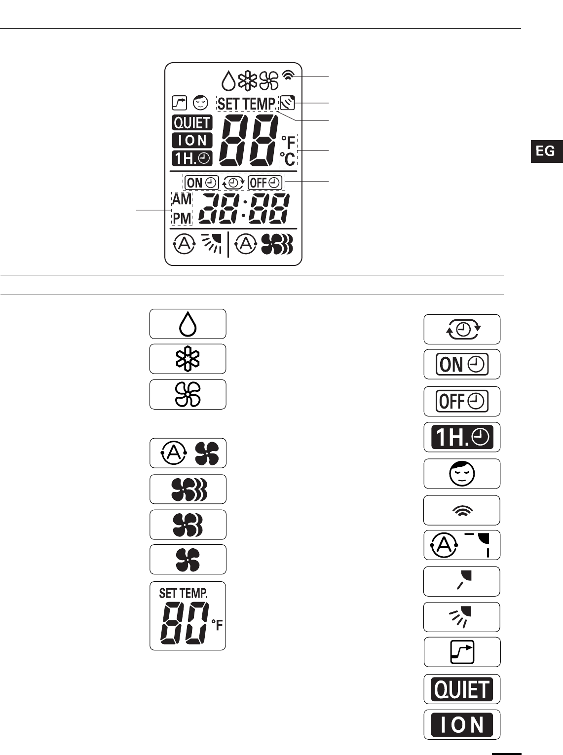
7
Remote Control Unit (Display)
(1) Operation mode
MILD DRY ..............................
COOL.....................................
FAN ........................................
(2) Fan speed
Automatic operation ...............
HIGH .....................................
MEDIUM.................................
LOW .......................................
(3) Temperature setting
60–86°F
When set to 80 °F
temperature indication............
(4) Timer
24-hour clock with ON/OFF
program Timer........................
ON Timer................................
OFF Timer..............................
1-hour OFF Timer...................
(5) NIGHT SETBACK ..................
(6) Confirmation of
transmission...........................
(7) Auto. fla.dication.....................
Flap angle indication ..............
Sweep indication ....................
(8) High power operation .............
(9) Quiet operation.......................
(10) ION operation.......................
Displayed when setting timer
Displayed when transmitting data
Displayed when indoor unit sensor
is in use
Displayed when setting
temperature
Displayed when temperature is
shown
Displayed when the
time display is set to
12-hour time.
Symbols
OI-803-7-EG
01_KS0971_En.fm Page 7 Monday, July 9, 2007 3:28 PM
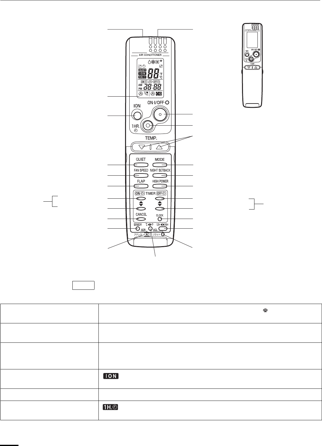
8
Remote Control Unit
The illustration above pictures the remote control unit after the cover has been
opened.
Transmitter When you press the buttons on the remote control unit, the mark appears in
the display to transmit the setting changes to the receiver in the air conditioner.
Sensor A temperature sensor inside the remote control unit senses the room
temperature.
Display Information on the operating conditions is displayed while the remote control unit
is switched on. If the unit is turned off, FLAP setting and FAN SPEED setting are
not displayed.
ION button : This button is for turning the negative ions generated during operation on
and off.
ON/OFF operation button This button is for turning the air conditioner on and off.
1 HR. TIMER button
(1-HOUR OFF TIMER)
: When you press this button, regardless of whether the unit is operating or
stopping, the unit operates for one hour and then shuts down.
Transmitter Sensor
(Cover closed)
Display
FAN SPEED selector button
FLAP button
ON TIME
setting
buttons Return button
Advance button
CANCEL button
SENSOR button
CLOCK button
ACL button
ON/OFF operation button
1 HR. TIMER button
Temperature setting buttons (TEMP.)
MODE selector button
Advance button
NIGHT SETBACK button
HIGH POWER button
OFF TIME
setting
buttons
Return button
ION button
ADDRESS switch
Temperature display
selector button
Time display selector button
QUIET button
NOTE
OI-803-8-EG
01_KS0971_En.fm Page 8 Monday, July 9, 2007 3:28 PM
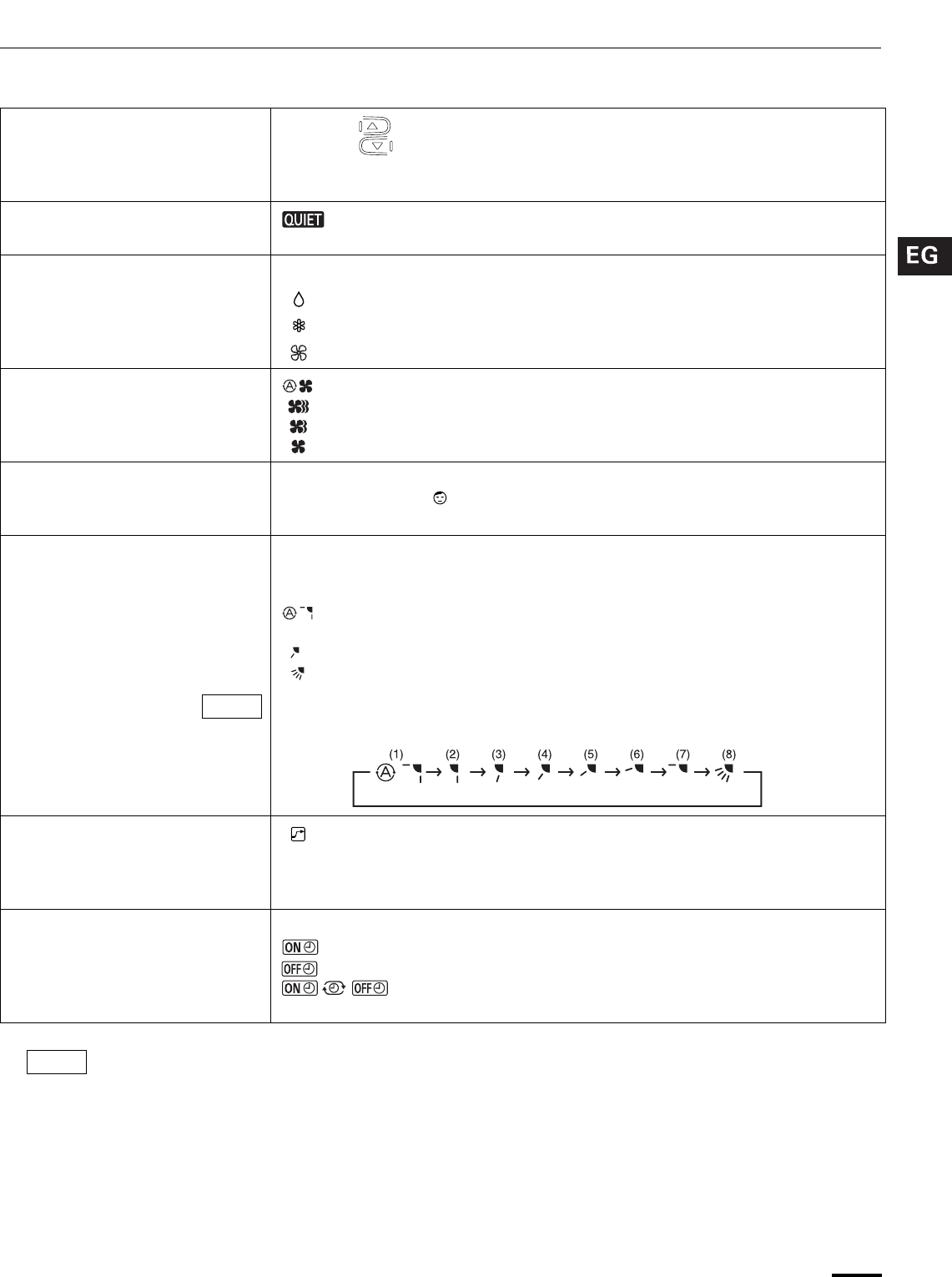
9
Remote Control Unit (continued)
Temperature setting buttons
(TEMP.)
Press the button to increase the set temperature.
Press the button to reduce the set temperature.
The temperature setting changes by 1 °C or 2 °F each time one of the TEMP.
buttons is pressed.
QUIET button : When you press this button, the fan rotates slower than the fan speed
setting to provide a quieter operating sound.
MODE selector button Use this button to select DRY, COOL or FAN mode.
(DRY) : The air conditioner reduces the humidity in the room.
(COOL) : The air conditioner makes the room cooler.
(FAN) : The air conditioner works only as a circulation fan.
FAN SPEED selector button : The air conditioner automatically decides the fan speeds.
: High fan speed
: Medium fan speed
: Low fan speed
NIGHT SETBACK button For details, see “4. Night Setback Mode”. When you press this button in the DRY
or COOL mode, the mark appears in the display, and the remote control unit
will automatically adjust the set temperature to save energy.
FLAP button Press this button either to select the setting of the airflow direction to the auto.
flap in each mode or one of the six possible positions manually or to select the
sweep function which moves the flap up and down automatically.
: Auto flap setting: If selected in a cooling or dry operation, the flap is set at
position (7) in the following chart.
: The airflow direction can be set manually. (six positions)
: The flap moves up and down automatically.
When you press the FLAP button, the air flow direction will be changed one by
one as follows.
HIGH POWER button : If this button is pressed during DRY, COOL or FAN operation, the unit
operates at maximum output for 30 minutes, regardless of the desired
temperature.
The fan speed is 1 step above “High”.
ON TIME/OFF TIME setting
buttons
No display: The timer does not operate.
: The air conditioner starts at the set time.
: The air conditioner stops at the set time.
: The air conditioner stops and starts, or starts and stops, at the
set times every day. For details, see “Setting the Timer”.
The indoor fan runs continuously when the system is in normal operation. It does not turn off when the
desired room temperature is reached. If Night Set Back mode is selected, the fan will turn off
intermittently during cooling operation in order to control air flow.
NOTE
SWEEP
NOTE
OI-803-9-EG
01_KS0971_En.fm Page 9 Monday, July 9, 2007 3:28 PM
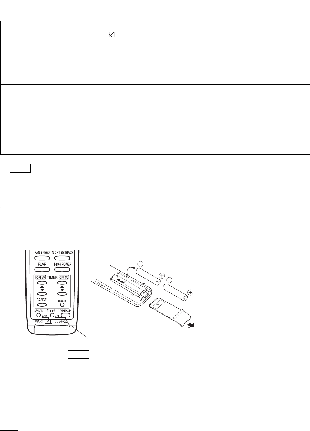
10
Remote Control Unit (continued)
Using the Remote Control Unit
SENSOR button When you press this button (use a small-tipped object such as a ballpoint pen),
the mark will appear at the display. And the room temperature is detected by
the sensor which is built into the indoor unit and the air conditioner is controlled
accordingly.
If the remote control is located near a heat source, such as a space heater or in direct
sunlight, press the SENSOR button to switch to the sensor on the indoor unit.
Temperature Display Selector button
This switches the temperature display between °C and °F.
Time Display Selector button This switches the time display between 24-hour time and 12-hour time.
ACL button (ALL CLEAR) Puts the remote control unit into pre-operation status. Always press this button
after replacing the batteries.
ADDRESS switch • The address switch changes to prevent mixing of signals from remote control
units when two air conditioners are installed next to each other. Normally, the
address switch is set to A. For more information, please contact the dealer
where you made the purchase.
• Normally, the tabs on the remote control unit should not be bent.
The remote control unit sends the temperature signal to the air conditioner regularly at five minute
intervals. If the signal from the remote control unit stops for more than 15 minutes due to the loss of the
remote control unit or other trouble, the air conditioner will switch to the temperature sensor which is built
into the indoor unit and control the room temperature. In these cases, the temperature around the remote
control unit may differ from the temperature detected at the air conditioner’s position.
How to Install Batteries
• The batteries last about six months, depending on how much you use
the remote control unit. Replace the batteries when the remote control
unit’s display fails to light, or when the remote control cannot be used to
change the air conditioner’s settings.
• Use two fresh leak-proof type-AAA alkaline batteries.
• In replacing batteries, follow the instructions as mentioned in the sub-
section “How to Install Batteries”.
• If you do not use the remote control unit more than 1 month, take out the
batteries.
NOTE
NOTE
1. Slide the cover in the direction
indicated by the arrow and remove it.
2. Install two AAA alkaline batteries.
Make sure the batteries point in the
direction marked in the battery
compartment.
3. Use a thin object such as the tip of a
pen to press the ACL button.
ACL button
NOTE
OI-803-10-EG
01_KS0971_En.fm Page 10 Monday, July 9, 2007 3:28 PM
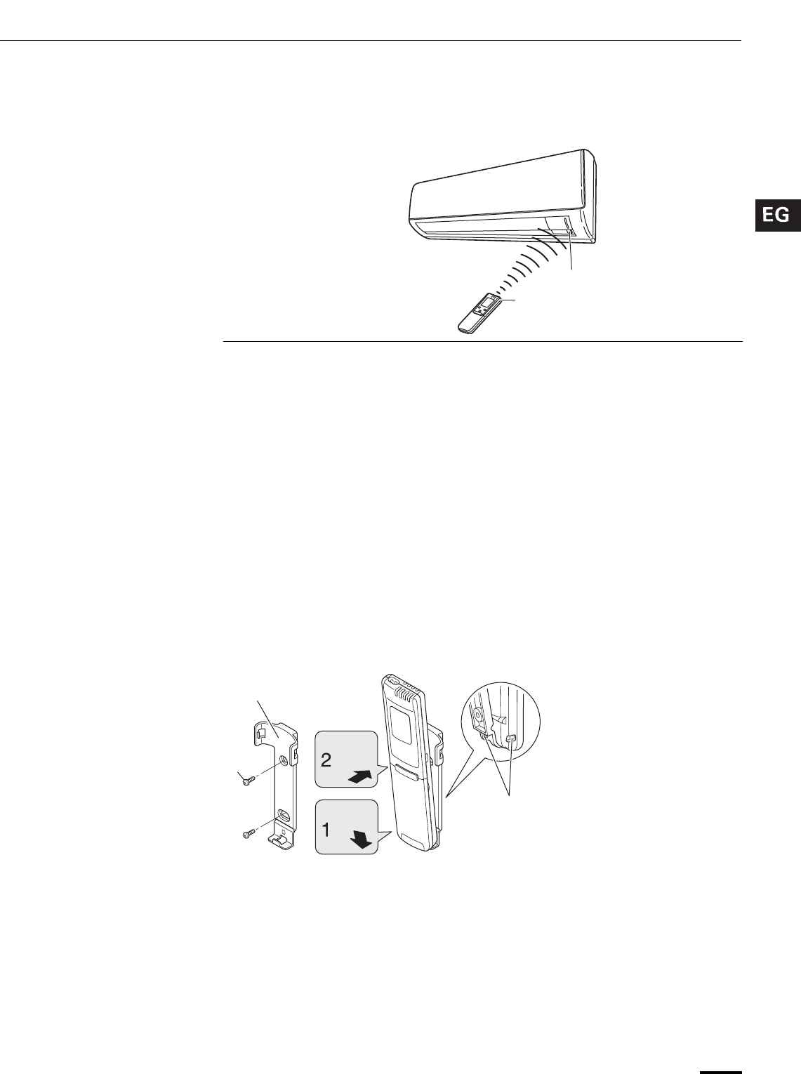
11
Using the Remote Control Unit (continued)
How to Use the Remote
Control Unit
When using the remote control unit, always point the unit’s transmitter head
directly at the air conditioner’s receiver.
Remote Control Unit
Installation Position
The remote control unit may be operated either from a non-fixed position or from
a wall-mounted position. To ensure that the air conditioner operates correctly, DO
NOT install the remote control unit in the following places:
DO NOT • In direct sunlight
• Behind a curtain or other places where it is covered
• More than 26 feet (8 m) away from the air conditioner
• In the path of the air conditioner’s airstream
• Where it may become extremely hot or cold
• Where it may be subject to electrical or magnetic noise
• Where there is an obstacle between the remote control unit and air conditioner
(since a check signal is sent from the remote control unit every 5 minutes)
Mounting the Remote Control
Unit
Before mounting the remote control unit, press the ON/OFF operation button at
the mounting location to make sure that the air conditioner operates from that
location. The indoor unit should make a beeping sound to indicate that it has
received the signal.
To take out the remote control unit, pull it forward.
When Holding the Remote
Control Unit
• When using the remote control unit and during air conditioner operation, the
transmitter on the remote control unit should be pointed toward the receiver on
the indoor unit.
• Make sure that there are no objects between the remote control unit and
receiver which could block the signal.
Air conditioner
(Indoor unit)
Receiver
Remote control
unit
(Transmitter head)
Remote control
unit mount
Mounting screws
5/32 x 5/8" (4 x 16 mm)
(included)
Rear side
Hole
• To prevent loss of the remote control unit,
you can connect the remote control unit to
the mount by passing a string through the
remote control unit and attachment hole.
Press
Set in
place
OI-803-11-EG
01_KS0971_En.fm Page 11 Monday, July 9, 2007 3:28 PM
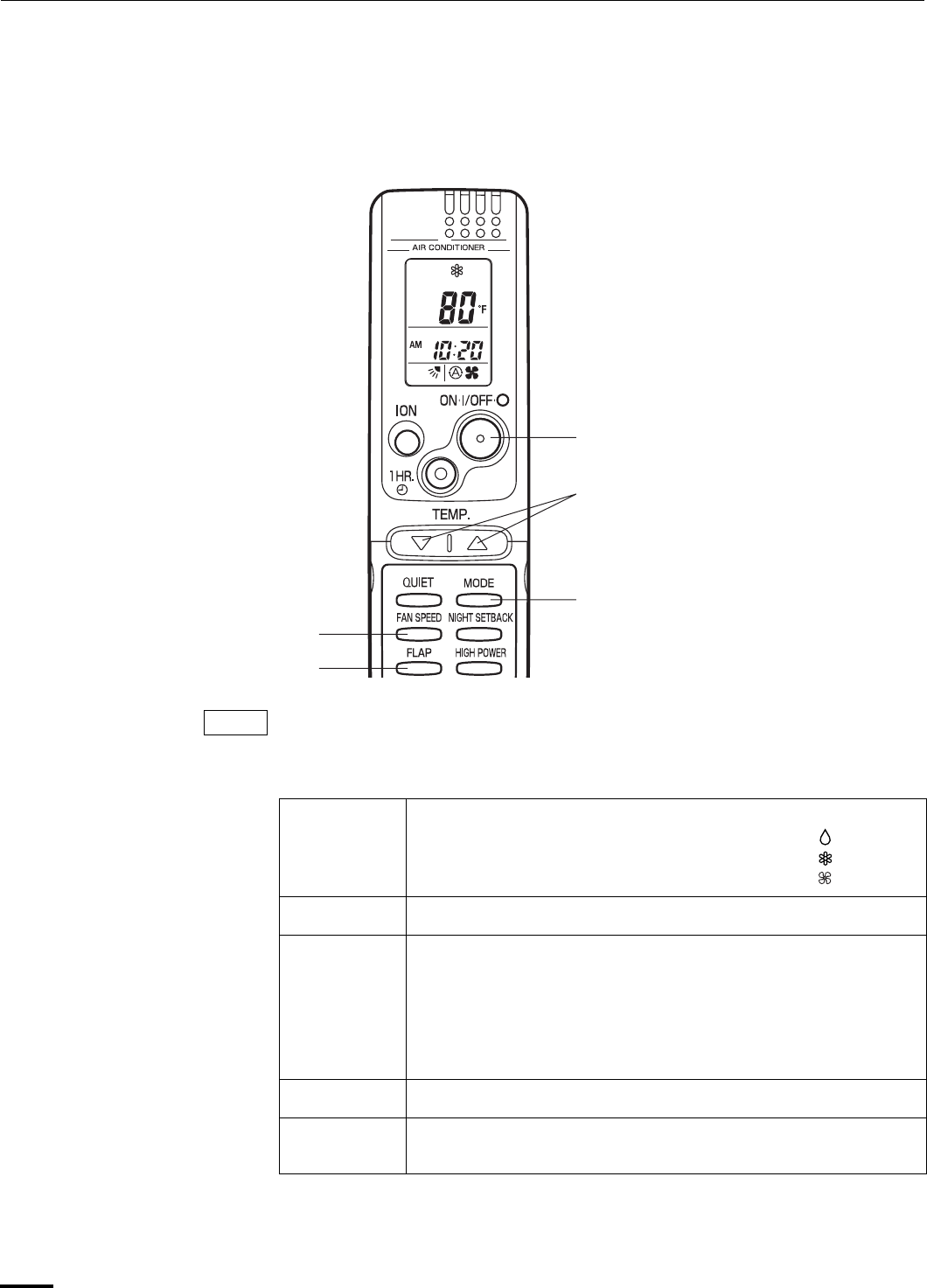
12
Operation with the Remote Control
Unit
1. Operation
Check that the circuit breaker on the power panel is turned on.
Press the setting buttons as described below and change the settings as desired.
STEP 1 Press the MODE selector button and select the desired mode.
For dehumidifying operation →
For cooling operation →
For fan only operation →
STEP 2 To start the air conditioner, press the ON/OFF operation button.
STEP 3 Press the TEMP. setting buttons to change the temperature
setting to the desired temperature.
Adjustable temperature range:
STEP 4 Set the FAN SPEED selector button to the setting you want.
STEP 5 Press the FLAP button and set the airflow direction as desired.
(Refer to “Adjusting the Airflow Direction” on page 20.)
To stop the air conditioner, press the ON/OFF operation button again.
STEP 2
STEP 1
STEP 3
STEP 4
STEP 5
NOTE
30 °C max.
16 °C min.
or 86 °F max.
60 °F min.
OI-803-12-EG
01_KS0971_En.fm Page 12 Monday, July 9, 2007 3:28 PM
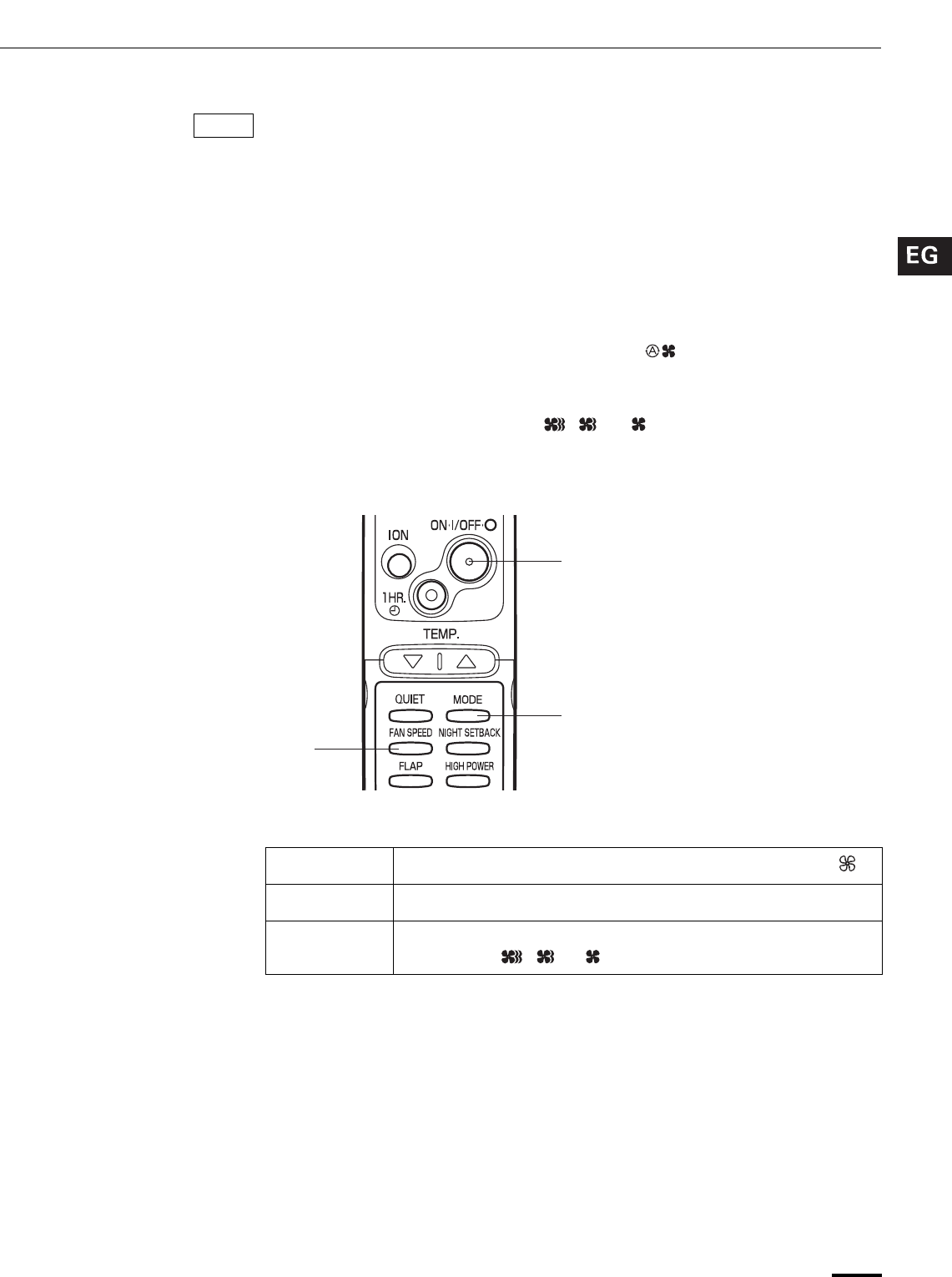
13
Operation with the Remote Control Unit (continued)
• Choose the best position in the room for the remote control unit, which also
acts as the sensor for room comfort and transmits the operating instructions.
Once you’ve found this best position, always keep the remote control unit
there.
• This appliance has a built-in 5-minute time delay circuit to ensure reliable
operation. When the operation button is pressed, the compressor will start
running within three minutes. In the event of power failure, the unit will stop.
2. Adjusting the Fan Speed
A. Automatic fan speed Simply set the FAN SPEED selector button to the position.
This automatically sets the best fan speed for the room temperature.
B. Manual fan speed If you want to adjust fan speed manually during operation, just set the FAN
SPEED selector button as desired. [ , , or ]
3. Fan Only
If you want to circulate air without any temperature control, follow these steps:
STEP 1 Press the MODE selector button to switch to the fan mode .
STEP 2 Press the ON/OFF operation button.
STEP 3 Press the FAN SPEED selector button to select the fan speed of
your choice ( , or ).
NOTE
STEP 2
STEP 1
STEP 3
OI-803-13-EG
01_KS0971_En.fm Page 13 Monday, July 9, 2007 3:28 PM
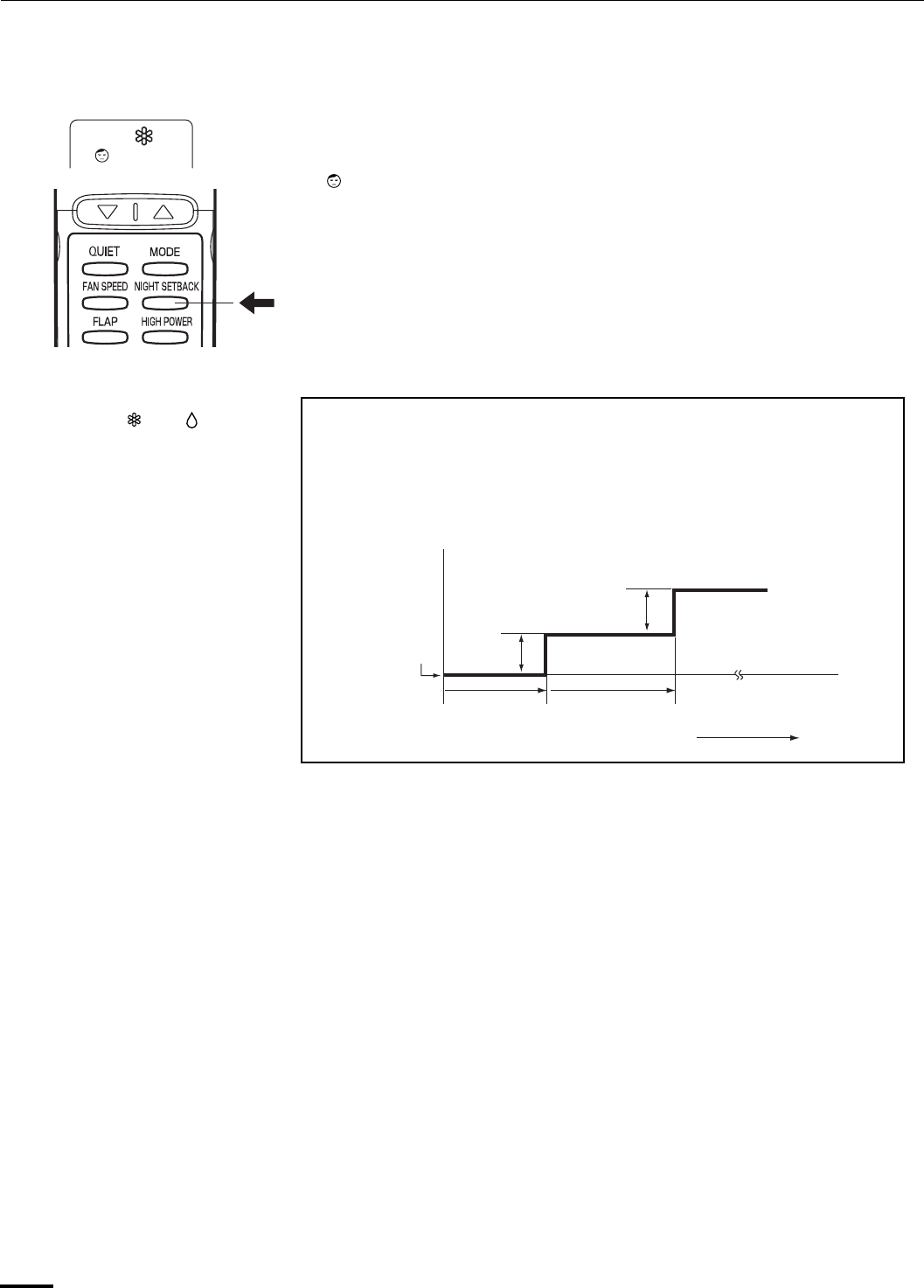
14
Operation with the Remote Control Unit (continued)
4. Night Setback Mode
Night Setback Mode is used for saving energy.
Press the NIGHT SETBACK button while operation.
The mark appears in the display.
To release the night setback function, press the NIGHT SETBACK button again.
In Cooling and DRY
Mode: ( and ) When the night setback mode is selected, the air conditioner automatically
raises the temperature setting 2 °F when 30 minutes have passed after the
selection was made, and then another 2 °F after another 30 minutes have
passed, regardless of the indoor temperature when night setback was
selected. This enables you to save energy without sacrificing comfort. This
function is convenient when gentle cooling is needed.
Setting
temperature
Press the NIGHT
SETBACK button
30 min. 30 min. Time
2°F
2°F
OI-803-14-EG
01_KS0971_En.fm Page 14 Monday, July 9, 2007 3:28 PM
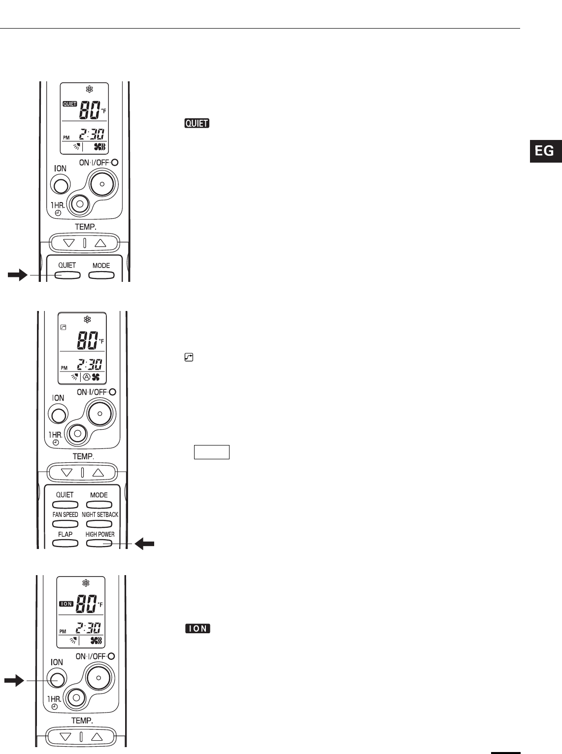
15
Operation with the Remote Control Unit (continued)
5. QUIET Mode
QUIET Mode is used to reduce the fan sound of the indoor unit.
Press the QUIET button.
The mark appears in the display.
To cancel, press QUIET button again.
• In QUIET Mode, the fan rotates at a slower speed than the fan speed setting.
• If the unit is already operating with a very low airflow, the fan sound may not
change even if the QUIET button is pressed.
6. HIGH POWER Mode
HIGH POWER mode can be used to increase the output of the indoor unit for all
operation modes.
Press the HIGH POWER button.
The mark appears in the display.
To cancel, press HIGH POWER button again.
• When the HIGH POWER button is pressed, the unit operates at maximum
output for 30 minutes, regardless of the desired temperature. The fan speed is
1 step above “High”.
• QUIET Mode and HIGH POWER Mode cannot be used at the same time.
7. ION Mode
The ION mode is used during operation to generate negative ions that freshen up
the air in the room.
Press the ION button.
The mark appears in the display.
To cancel, press ION button again.
• The indoor unit’s ION lamp lights up while negative ions are being generated.
• ION “on” is the remote control unit’s initial setting.
• The negative ions are generated from the negative ion generator.
• Depending on the operating conditions, the fan speed may be
increased by a small amount only.
NOTE
OI-803-15-EG
01_KS0971_En.fm Page 15 Monday, July 9, 2007 3:28 PM
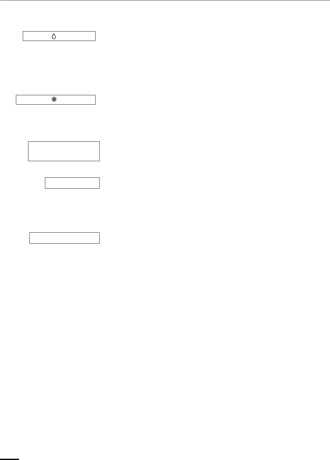
16
Special Remarks
How it works? • Once the room temperature reaches the level that was set, the unit’s operation
frequency is changed automatically.
• During DRY operation, the fan speed automatically runs at lower speed for
providing a comfortable breeze.
• ‘‘DRY’’ operation is not possible if the indoor temperature is 59 °F or less.
• Sometimes the indoor unit may not get to the set fan speed such as LOW and
QUIET under cool operation at very low outdoor temperatures due to the
indoor unit being protected from ice or frost when combined with the outdoor
unit for Low Ambient Cooling models.
• In the event of power failure, the unit will stop. When the power is resumed,
the unit will restart automatically within five minutes by the remote control unit.
Clicking sound is heard from
the air conditioner
• In cooling operation, any plastic parts may shrink due to a sudden
temperature change. In this event, a clicking sound may occur. This is normal,
and the sound will soon disappear.
• The remote control unit sends the setting condition to the air conditioner
regularly at five minute intervals.
‘‘DRY’’ ( ) Operation
Cooling ( ) Operation
Power failure during
operation
Clicking Sound
Remote Control Unit
OI-803-16-EG
01_KS0971_En.fm Page 16 Monday, July 9, 2007 3:28 PM
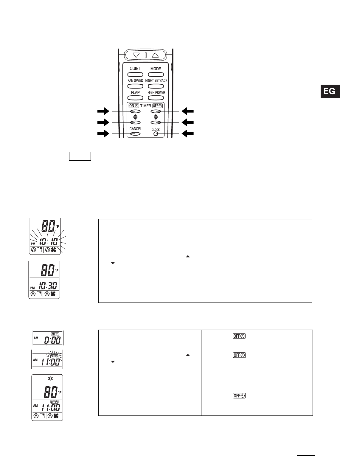
17
Setting the Timer
In the descriptions below, the following settings are used for the temperature and
time indicator selector button on the bottom front section of the remote control.
• Temperature: °F
• Time: AM, PM
1. How to set the present
time
(Example) To set to 10:30 pm.
2. How to set the OFF time (Example) To stop the air conditioner at 11:00 am.
NOTE
Operation Indication
1. Press the CLOCK button once if
the time indicator is not flashing.
The time indication alone flashes.
2. Press the Advance, Return ( ,
) button until PM 10:30 is
displayed.
The time can be set in 1-minute
increments. Holding down the button
advances the time rapidly in 10-minute
increments.
3. Press the CLOCK button again. This completes the setting of the
current time.
1. Press the OFF TIME setting
button once.
The timer indication is displayed,
and the present OFF time is shown.
2. Press the Advance, Return ( ,
) button until AM 11:00 is
displayed.
The timer indication blinks.
The time can be set in 10-minute
increments. Holding down the button
advances the time rapidly in 10-minute
increments.
3. Wait a few seconds, and then the
setting is complete.
The timer indication stops
blinking and the present time is
displayed.
OI-803-17-EG
01_KS0971_En.fm Page 17 Monday, July 9, 2007 3:28 PM
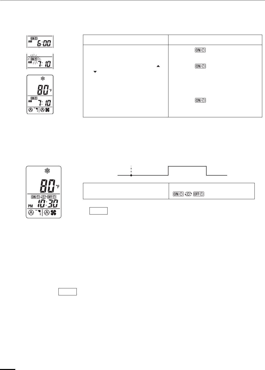
18
Setting the Timer (continued)
3. How to set the ON time (Example) To start operation at 7:10 am.
4. How to set DAILY ON/OFF
REPEAT timer
(Example) To start operation at 7:10 am. and stop the air conditioner at 11:00 am.
To cancel a timer program • Press the CANCEL button.
• When either an ON or OFF timer is to be canceled, press the button
corresponding to the timer whose program is to be canceled, and then press
the CANCEL button.
• The airflow direction, fan speed and temperature setting can be changed after
a timer program has been set even when the unit is stopped. Even when
operation is stopped during an ON timer program, the unit will start operating
when the set time is reached provided that the program is not canceled.
• When the ON timer and OFF timer are set to the same time, the timer
operates as if it is turned off.
Operation Indication
1. Press the ON TIME setting
button once.
The timer indication is displayed,
and the present ON time is shown.
2. Press the Advance, Return ( ,
) button until AM 7:10 is
displayed.
The timer indication blinks.
The time can be set in 10-minute
increments. Holding down the button
advances the time rapidly in 10-minute
increments.
3. Wait a few seconds, and then
the setting is complete.
The timer indication stops
blinking and the present time is
displayed.
7:10 am.
ON
11:00 am.
OFF
10:30 pm.
Present time
1. Set the timer ON/OFF times as
shown in 2-1, 2, 3 and 3-1, 2, 3.
The present time 10:30 pm. and
are displayed.
• The ON/OFF combination timer uses the current time as the
reference, and it is activated starting from whichever set time
comes first.
• With the ON/OFF combination timer, the settings are repeated
every day.
• You can check the timer ON/OFF times after you have set them
by pressing the ON TIME and OFF TIME setting buttons.
NOTE
NOTE
OI-803-18-EG
01_KS0971_En.fm Page 18 Monday, July 9, 2007 3:28 PM
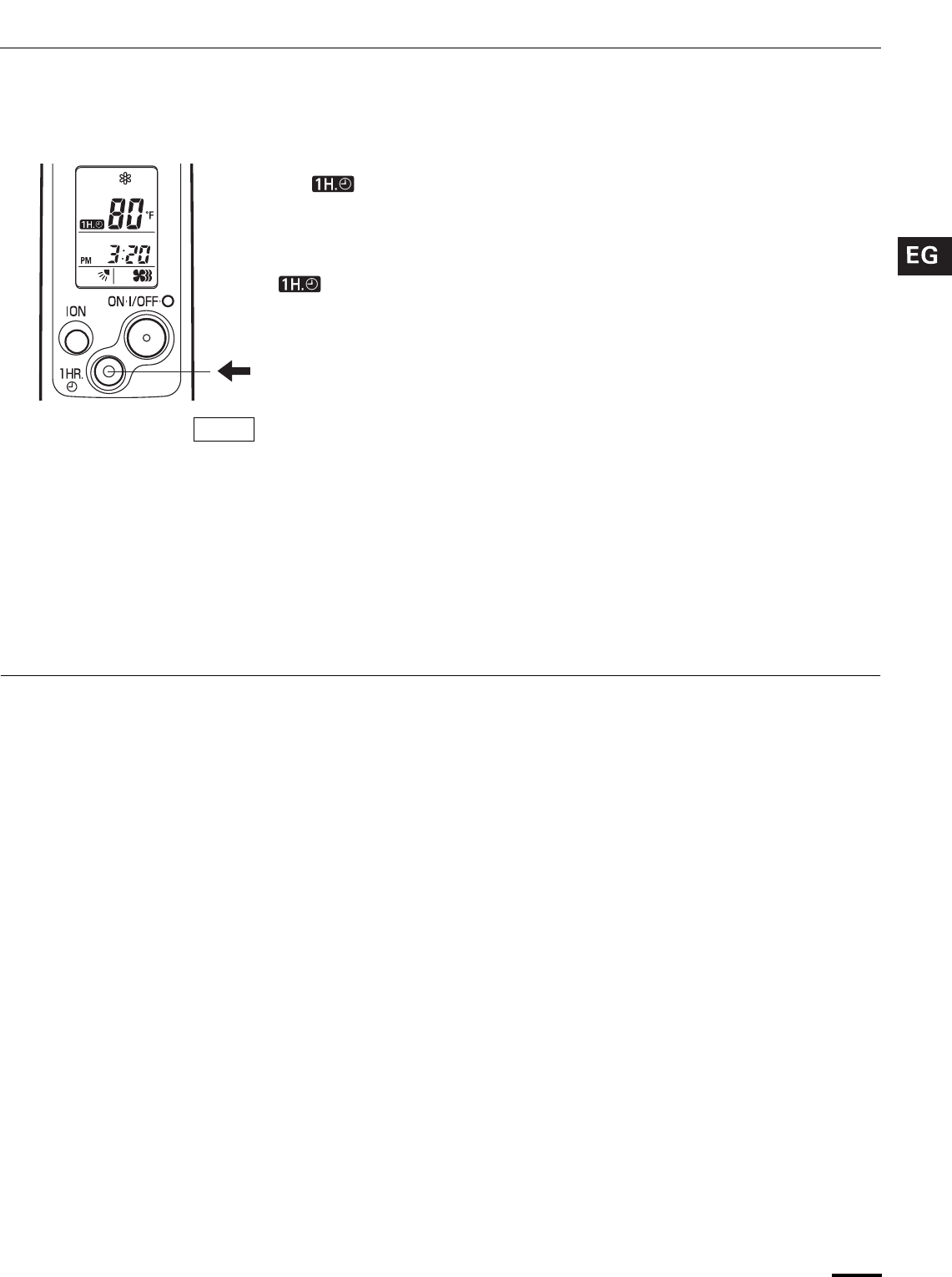
19
Using the 1-Hour OFF Timer
Tips for Energy Saving
1. 1-Hour OFF Timer This function causes the unit to operate for one hour and then stop,
regardless of whether the unit is on or off when this button is pressed.
The indicator in the display indicates that this function is operating.
Setting procedure:
Regardless of whether the unit is operating or stopped, press the 1 HR. TIMER
button.
appears in the display.
Cancellation procedure:
Press the ON/OFF operation button to turn the unit off, wait for the unit to stop
operating, and then press the ON/OFF operation button again.
The 1-Hour Timer function is now cancelled and the unit operates normally.
• If, while the 1-Hour Timer function is operating, the 1HR. TIMER button is
pressed once to cancel the function and then again, the unit continues to
operate for one hour from that point in time and then stops.
• It is not possible to use the OFF Timer and 1-Hour OFF Timer together.
Whichever function is set last takes precedence. If the 1 HR. TIMER button is
pressed while the TIMER OFF function operates, the OFF Timer is cancelled
and the unit will stop operating one hour later.
2. Operation together with the
DAILY ON/OFF REPEAT Timer
The 1-Hour OFF Timer setting is given priority over the DAILY ON/OFF REPEAT
setting.
Do not • Block the air intake and outlet of the unit. If they are obstructed, the unit
will not work well, and may be damaged.
• Let direct sunlight into the room. Use sunshades, blinds or curtains. If the walls
and ceiling of the room are warmed by the sun, it will take longer to cool the
room.
Do • Always try to keep the air filter clean. (Refer to “Care and Cleaning”.) A
clogged filter will impair the performance of the unit.
• To prevent conditioned air from escaping, keep windows, doors and any other
openings closed.
NOTE
OI-803-19-EG
01_KS0971_En.fm Page 19 Monday, July 9, 2007 3:28 PM
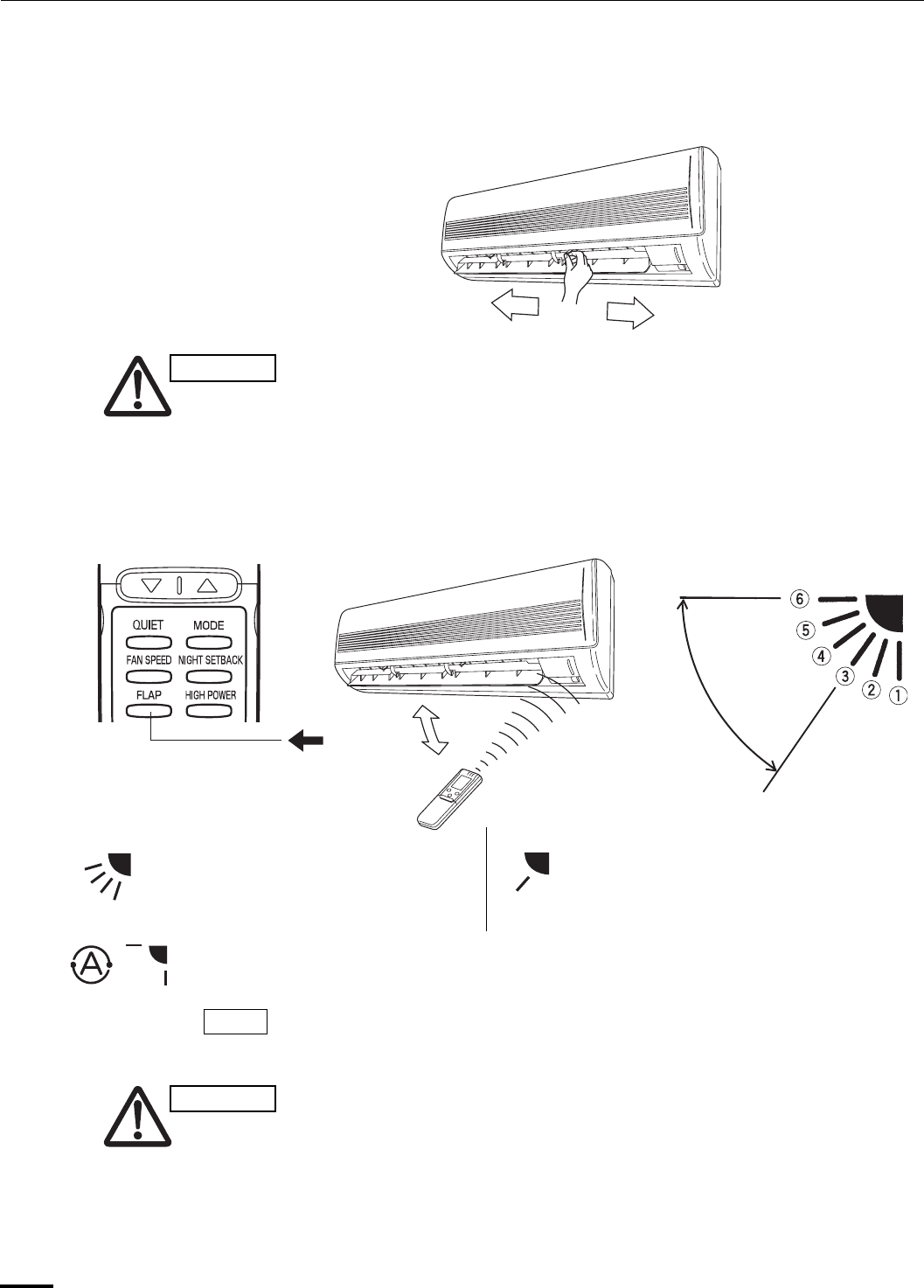
20
Adjusting the Airflow Direction
1. Horizontal The horizontal airflow can be adjusted by moving the vertical vanes with your
hands to the left or right.
When the humidity is high, the vertical vanes should be in the front
position during the cooling or dehumidifying operation. If the vertical
vanes are positioned all of the way to the right or left, condensation may
begin to form around the air vent and drip down.
2. Vertical The vertical airflow can be adjusted by moving the flap with the remote control
unit. Do not move the flap with your hands. Confirm that the remote control unit
has been turned on. Use the FLAP button to set either the sweep function or one
of the six airflow direction settings.
• The flap automatically closes when the unit is off.
• Use the FLAP button on the remote control to adjust the position of the
flap. If you move the flap by hand, the flap position according to the
remote control and the actual flap position may no longer match. If this
should happen, shut off the unit, wait for the flap to close, and then turn
on the unit again; the flap position will now be normal again.
• Do not have the flap pointed down during cooling operation.
Condensation may begin to form around the air vent and drip down.
CAUTION
A. Sweep function
The flap starts moving up and down to
deliver air over the sweep range.
C. Auto flap function
The flap is set to the recommended
position.
B. Setting the airflow manually
Referring to the above illustration, use the
FLAP button to set the airflow direction
within the range used during the cooling or
dehumidifying operation.
COOL
DRY
FAN
SWEEP
NOTE
CAUTION
OI-803-20-EG
01_KS0971_En.fm Page 20 Monday, July 9, 2007 3:28 PM
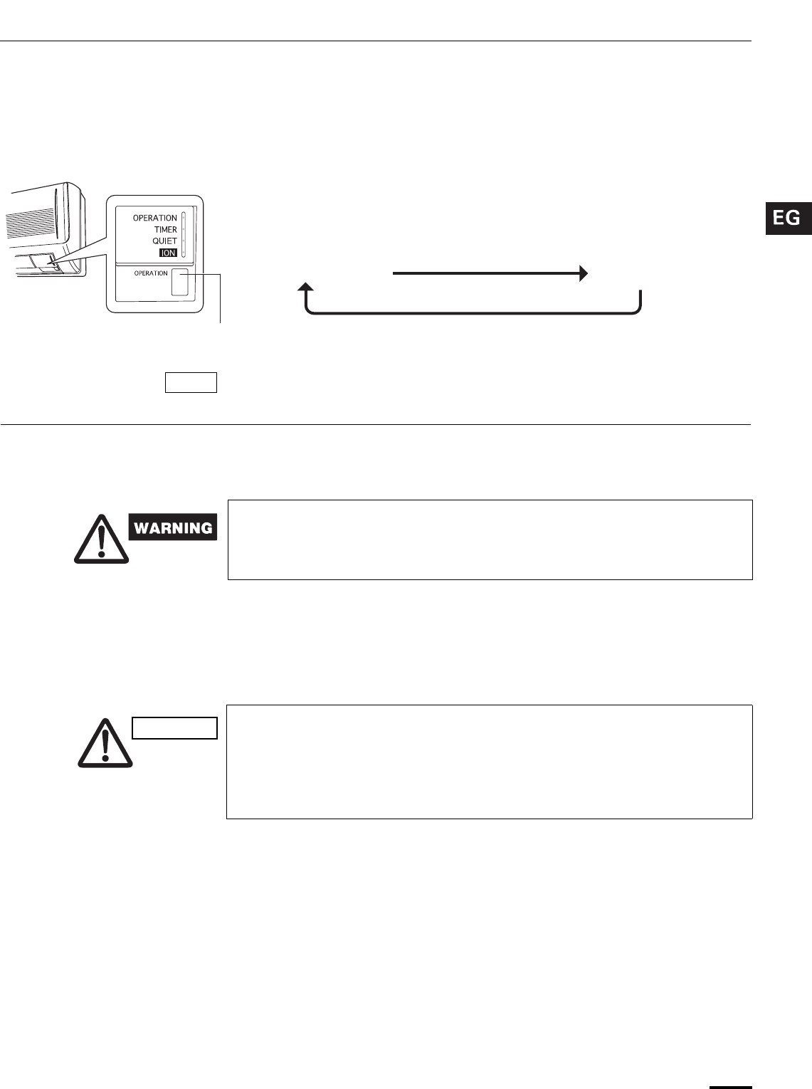
21
Operation without the Remote
Control Unit
Care and Cleaning
INDOOR UNIT If you have lost the remote control unit or it has trouble, follow the steps
below.
When the air conditioner is not running
Each time the OPERATION button is pressed, the operation mode changes
cyclically.
The temperature is set to the room temperature minus 4 °F during the cooling
operation, and the fan speed and flap are set to Auto.
1. For safety, be sure to turn the air conditioner off and also to disconnect
the power before cleaning.
2. Do not pour water on the indoor unit to clean it. This will damage the
internal components and cause an electric shock hazard.
Casing and Grille (Indoor Unit) Clean the casing and grille of the indoor unit with a vacuum cleaner brush, or
wipe them with a clean, soft cloth.
If these parts are stained, use a clean cloth moistened with a mild liquid
detergent. When cleaning the grille, be careful not to force the vanes out of place.
1. Never use solvents, or harsh chemicals when cleaning the indoor unit.
Do not wipe the plastic casing using very hot water.
2. Some metal edges and the fins are sharp and may cause injury if
handled improperly; be especially careful when you clean these parts.
3. The internal coil and other components of the outdoor unit must be
cleaned every year. Consult your dealer or service center.
OPERATION button
Cooling operation Stop
NOTE
CAUTION
OI-803-21-EG
01_KS0971_En.fm Page 21 Monday, July 9, 2007 3:28 PM
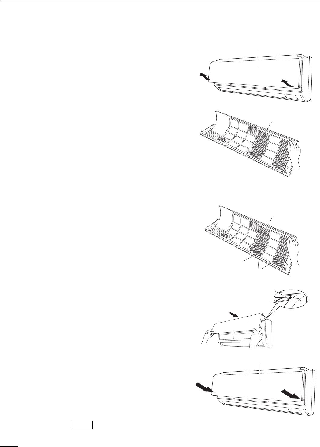
22
Care and Cleaning (continued)
Anti-Mold Filter The anti-mold filter behind the air intake grille should be checked and cleaned at
least once every two weeks.
How to remove the anti-mold
filter
1. Grasp both ends of the air
intake grille, and remove it by
opening towards the front and
pulling towards you.
2. Remove the anti-mold filter
attached to the rear of the air
intake grille.
Cleaning Use a vacuum cleaner to remove light dust. If there is sticky dust on the filter,
wash the filter in lukewarm, soapy water, rinse it in clean water, and dry it.
How to replace the anti-mold
filter
1. With the FRONT mark of the
anti-mold filter at the front,
align the two indentions near
the mark with the hooks at the
rear of the air intake grille, and
then mount the anti-mold filter.
2. Allow the edge of the air intake
grille to slide into the top of the
indoor unit, and then insert it
all the way inside.
3. Press in the bottom right and
left corners of the air intake
grille to attach the indoor unit.
Attach so that the round pins at the top right and left corners of the air intake grille
are inserted into the grooves at the top right and left of the indoor unit.
Air intake grille
Anti-mold filter
Anti-mold filter
FRONT mark
Hook
Air intake grille
Groove
Pin
Air intake grille
NOTE
OI-803-22-EG
01_KS0971_En.fm Page 22 Monday, July 9, 2007 3:28 PM
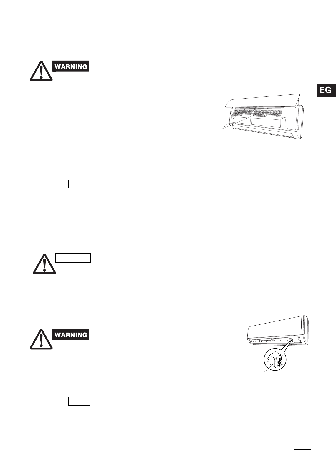
23
Care and Cleaning (continued)
Air Clean Filter The air clean filter removes dust and dirt from the air, and reduces odors and
smoke from tobacco.
This air clean filter cannot remove harmful gases or vapors nor ventilate air in
the room. You must open doors or windows frequently when you use gas or oil
heating appliances. Otherwise there is a risk of suffocation in extreme cases.
How to install the air clean
filter
The air clean filter needs to be installed behind the air intake grille.
1. Remove the air intake grille.
2. Install the air clean filter in the
position shown in the figure.
3. Remount the air intake grille.
How to clean the air clean filter • In general, the filter should be sucked to remove dust in low fan speed of a
vacuum cleaner once every three months.
• If there is heavily grime on the filter, soak the filter in lukewarm water with
neutral detergent diluted 1:500 for 1 to 2 minutes then wash it.
• Rinse the filter in clean water, then let it dry on the towel in room temperature.
• Do not bend nor give excessive force onto the air clean filter.
• If the filter surface is heavily blocked with dirt or damaged, replace it with new
one. Purchase a replacement filter at your local dealer. (model STK-FDXB)
Cleaning the main unit and
remote control unit
• Wipe clean using a soft, dry cloth.
• To remove stubborn dirt, moisten a cloth in warm water no hotter than 104 °F,
wring thoroughly, and then wipe.
• The air intake grille can be removed in order to wash it with water.
Removing and remounting the
air intake grille
Refer to “How to remove the anti-mold filter” and “How to replace the anti-mold
filter” on page 22.
When using a footstool or the like, be careful not to let it tip over.
Washing the grille with water • Clean the grille gently using a soft sponge, or the like. Then wipe away any
remaining moisture.
• Neutral detergent may be used to remove stubborn dirt. Then rinse thoroughly
with water and wipe away any remaining moisture.
Cleaning the negative ion
generator
Follow the steps below when the
generator has become dirty.
For safety, be sure to turn the air
conditioner off and also to disconnect
the power before cleaning.
Remove the dust on the negative ion
generator.
• Use a toothbrush, etc. to dust off the end.
• Use a cotton swab, etc., to clean around
the generator inside the plastic case,
taking care not to touch the electrodes.
• During use, the negative ion generator and other metal parts may become
discolored: this is normal and not indicative of malfunctioning.
• If the dirt on and around the negative ion generator is left to build up, a puffing or
sputtering sound will eventually be heard. In this case, clean the generator
immediately.
• Do not apply excessive force while performing maintenance.
Air clean filter
NOTE
CAUTION
Negative ion generator
(metal electrodes inside
plastic case)
NOTE
OI-803-23-EG
01_KS0971_En.fm Page 23 Monday, July 9, 2007 3:28 PM

24
Troubleshooting
If your air conditioner does not work properly, first check the following points before requesting service. If it still does not
work properly, contact your dealer or service center.
Operating Range
The air conditioner is operable within the temperature ranges as listed below:
For Cooling Only Models : C0971, C1271
For Low Ambient Cooling Models : CL0971, CL1271
Trouble Possible Cause Remedy
Air conditioner does not run at all. 1. Power failure. 1. Restore power.
2. Leakage circuit breaker tripped. 2. Contact service center.
3. Line voltage is too low. 3. Consult your electrician or dealer.
4. Batteries in remote control unit have
run down.
4. Replace batteries.
OPERATION lamp blinks and air
conditioner does not operate.
Trouble in system. Contact service center.
Compressor runs but soon stops. Obstruction in front of condenser coil. Remove obstruction.
Poor cooling performance. 1. Dirty or clogged air filter. 1. Clean air filter to improve airflow.
2. Heat source or many people in room. 2. Eliminate heat source if possible.
3. Doors and/or windows are open. 3. Shut them to keep the heat out.
4. Obstacle near air intake or air
discharge port.
4. Remove it to ensure good airflow.
5. Thermostat is set too high for cooling. 5. Set the temperature lower.
Clicking sound is heard from the air
conditioner.
In cooling operation, any plastic parts
may shrink due to a sudden
temperature change. In this event, a
clicking sound may occur.
This is normal, and the sound will soon
disappear.
OPERATION lamp lights but outdoor
unit will not run.
1. The use of cellular phones near the
air conditioner may cause
disturbance to its normal operation.
1. Turn off the power then restart the
air conditioner after a while.
2. Consult your dealer.
Temperature Indoor air temperature Outdoor air temperature
COOLING Max. 95 °F DB / 71 °F WB 115 °F DB
Min. 67 °F DB / 57 °F WB 67 °F DB
Temperature Indoor air temperature Outdoor air temperature
COOLING Max. 95 °F DB / 71 °F WB 115 °F DB
Min. 67 °F DB / 57 °F WB 0 °F DB
OI-803-24-EG
01_KS0971_En.fm Page 24 Monday, July 9, 2007 3:28 PM

INSTALLATION INSTRUCTIONS
KS0971+C0971
+CL0971
KS1271+C1271
+CL1271
(II-852-6-4189-991-00-6)
APPENDIX B
A-2
85264189991006 © SANYO 2007
Contents
Page
IMPORTANT!
Please Read Before Starting .................................. 2
1. GENERAL .......................................................... 3
1-1. Tools Required for Installation (not supplied)
1-2. Accessories Supplied with Unit
1-3. Optional Copper Tubing Kit
1-4. Type of Copper Tube and Insulation Material
1-5. Additional Materials Required for Installation
2. INSTALLATION SITE SELECTION ................... 4
2-1. Indoor Unit
2-2. Outdoor Unit
2-3. Baffle Plate for the Outdoor Unit
3. HOW TO INSTALL THE INDOOR UNIT ............. 8
3-1. Remove the Rear Panel from the Unit
3-2. Make a Hole
3-3. Install the Rear Panel on the Wall
3-4. Remove the Grille to Install the Indoor Unit
3-5. Shape the Indoor Side Tubing
3-6. Wiring Instructions
3-7. Recommended Wire Length and Diameter
3-8. Wiring Instructions for Inter-unit Connections
3-9. Mounting
3-10. Drain Hose
4. HOW TO INSTALL THE OUTDOOR UNIT ....... 18
4-1. Wiring Instructions for the Outdoor Unit
5. REFRIGERANT TUBING .................................. 19
5-1. Use of the Flaring Method
5-2. Flaring Procedure with a Flare Tool
5-3. Caution before Connecting Tubes Tightly
5-4. Connecting Tubing between Indoor and
Outdoor Units
5-5. Insulation of Refrigerant Tubing
5-6. Taping the Tubes
5-7. Finishing the Installation
6. AIR PURGING................................................... 21
IAir Purging with a Vacuum Pump (for Test Run)
IBasic Functions of the Service Valves
IPump Down
INSTALLATION INSTRUCTIONS
Model Combinations
Combine indoor and outdoor units only as listed
below.
Indoor Unit Outdoor Unit
KS0971 C0971
CL0971
KS1271 C1271
CL1271
Power Source:
60 Hz, single-phase, 115 V
– Inverter Split System Air Conditioner – COOL/ DRY Model
This air conditioner uses the new refrigerant R410A.
Be sure to read the yellow instruction sheet
attached to the outdoor unit for models using the
new refrigerant R410A.
The illustrations are based on the typical appearance of
a standard model. Consequently, the shape may differ
from that of the air conditioner that you are installing.
NOTE
7. REMOTE CONTROL UNIT INSTALLATION
POSITION ......................................................... 25
7-1. Mounting on a Wall
8. ADDRESS SWITCH .......................................... 26
8-1. Address Setting of the Remote
Control Unit
SANYO Commercial Solutions In Canada
A Division of SANYO North America Corporation SANYO Canada Inc.
Cornerstone Business Park, 1-300 Applewood Crescent, Concord
1062 Thorndale Avenue, Ontario, L4K 5C7, Canada
Bensenville, IL 60106, U.S.A.
W
Refrigerant service valve size = 5/16"
NOTE
07-105 KS0971-1271 5/10/07 9:17 AM Page a
2
IMPORTANT!
Please Read Before Starting
This air conditioning system meets strict safety and operating
standards. As the installer or service person, it is an important
part of your job to install or service the system so it operates
safely and efficiently.
For safe installation and trouble-free operation, you
must:
GCarefully read this instruction booklet before beginning.
GFollow each installation or repair step exactly as shown.
GObserve all local, state, and national electrical codes.
GPay close attention to all warning and caution notices
given in this manual.
This symbol refers to a hazard
or unsafe practice which can
result in severe personal injury
or death.
This symbol refers to a hazard
or unsafe practice which can
result in personal injury or prod-
uct or property damage.
If Necessary, Get Help
These instructions are all you need for most installation
sites and maintenance conditions. If you require help for a
special problem, contact our sales/service outlet or your
certified dealer for additional instructions.
In Case of Improper Installation
The manufacturer shall in no way be responsible for improp-
er installation or maintenance service, including failure to
follow the instructions in this document.
SPECIAL PRECAUTIONS
When Wiring
ELECTRICAL SHOCK CAN CAUSE SEVERE
PERSONAL INJURY OR DEATH. ONLY A
QUALIFIED, EXPERIENCED ELECTRICIAN
SHOULD ATTEMPT TO WIRE THIS SYSTEM.
• Do not supply power to the unit until all wiring and tubing
are completed or reconnected and checked.
• Highly dangerous electrical voltages are used in this
system. Carefully refer to the wiring diagram and these
instructions when wiring. Improper connections and
inadequate grounding can cause accidental injury or
death.
• Ground the unit following local electrical codes.
• Connect all wiring tightly. Loose wiring may cause over-
heating at connection points and a possible fire hazard.
When Transporting
Be careful when picking up and moving the indoor and out-
door units. Get a partner to help, and bend your knees when
lifting to reduce strain on your back. Sharp edges or thin alu-
minum fins on the air conditioner can cut your fingers.
When Installing…
…In a Ceiling or Wall
Make sure the ceiling/wall is strong enough to hold the
unit’s weight. It may be necessary to construct a strong
wood or metal frame to provide added support.
…In a Room
Properly insulate any tubing run inside a room to prevent
“sweating” that can cause dripping and water damage to
walls and floors.
…In Moist or Uneven Locations
Use a raised concrete pad or concrete blocks to provide a
solid, level foundation for the outdoor unit. This prevents
water damage and abnormal vibration.
…In an Area with High Winds
Securely anchor the outdoor unit down with bolts and a
metal frame. Provide a suitable air baffle.
…In a Snowy Area (for Heat Pump-type Systems)
Install the outdoor unit on a raised platform that is higher
than drifting snow. Provide snow vents.
When Connecting Refrigerant Tubing
• Use the flare method for connecting tubing.
• Apply refrigerant lubricant to the matching surfaces of
the flare and union tubes before connecting them, then
tighten the nut with a torque wrench for a leak-free
connection.
• Check carefully for leaks before starting the test run.
When Servicing
• Turn the power OFF at the main power box (mains) before
opening the unit to check or repair electrical parts and
wiring.
• Keep your fingers and clothing away from any moving
parts.
• Clean up the site after you finish, remembering to check
that no metal scraps or bits of wiring have been left inside
the unit being serviced.
Others
• Ventilate any enclosed areas when installing or testing
the refrigeration system. Escaped refrigerant gas, on
contact with fire or heat, can produce dangerously
toxic gas.
• Confirm upon completing installation that no refrigerant
gas is leaking. If escaped gas comes in contact with a
stove, gas water heater, electric room heater or other heat
source, it can produce dangerously toxic gas.
WARNING
WARNING
CAUTION
CAUTION
07-105 KS0971-1271 5/10/07 9:17 AM Page 2
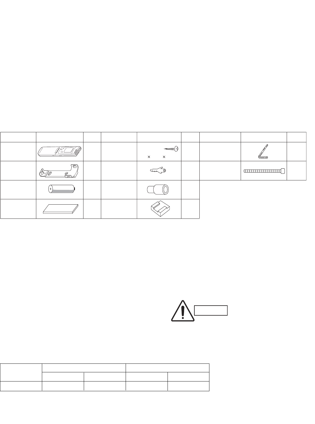
3
1. General
This booklet briefly outlines where and how to install the
air conditioning system. Please read over the entire set
of instructions for the indoor and outdoor units and make
sure all accessory parts listed are with the system before
beginning.
1-1. Tools Required for Installation (not supplied)
1. Standard screwdriver
2. Phillips head screwdriver
3. Knife or wire stripper
4. Tape measure
5. Carpenter’s level
6. Sabre saw or key hole saw
7. Hacksaw
8. Core bits
9. Hammer
10. Drill
11. Tube cutter
12. Tube flaring tool
13. Torque wrench
14. Adjustable wrench
15. Reamer (for deburring)
1-2. Accessories Supplied with Unit
Table 1
1-3. Optional Copper Tubing Kit
Copper tubing for connecting the outdoor unit to the
indoor unit is available in kits which contain the narrow
and wide tubing, fittings and insulation. Consult your
nearest sales outlet or A/C workshop.
1-4. Type of Copper Tube and Insulation Material
If you wish to purchase these materials separately from
a local source, you will need:
1. Deoxidized annealed copper tube for refrigerant tub-
ing as detailed in Table 2.
Cut each tube to the appropriate lengths 1' to 1'4"
(30 cm to 40 cm) to dampen vibration between units.
Table 2
2. Foamed polyethylene insulation for the specified
copper tubes as required to precise length of tubing.
Wall thickness of the insulation should be not less
than 5/16" (8 mm).
3. Use insulated copper wire for field wiring. Wire size
varies with the total length of wiring. Refer to 3-6.
Wiring Instructions for details.
PartsFigure Q’ty PartsFigure Q’ty
1
1
2
Rawl plug
Tapping screw Hex wrench*
Tr uss-head
Phillips
5/325/8" (4 16 mm)
1
2
AAA alkaline
battery
10
8
1
PartsFigure Q’ty
Remote
control unit
Remote control
unit holder
Air clean filter
1
*Packed in the outdoor unit.
Clamp
Drain hose
adapter
Cushion
rubber*4
CAUTION Check local electrical codes
and regulations before
obtaining wire. Also, check
any specified instructions or
limitations.
Model
Narrow Tube Wide Tube
Outer Dia. Thickness Outer Dia. Thickness
KS0971/1271 1/4" (6.35 mm) 0.0314" (0.8 mm) 3/8" (9.52 mm) 0.0314" (0.8 mm)
07-105 KS0971-1271 5/10/07 9:17 AM Page 3
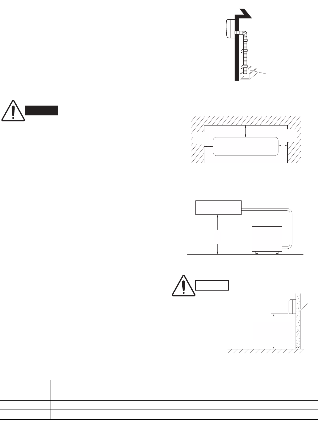
4
1-5. Additional Materials Required for Installation
1. Refrigeration (armored) tape
2. Insulated staples or clamps for connecting wire
(See local codes)
3. Putty
4. Refrigeration lubricant
5. Clamps or saddles to secure refrigerant tubing
2. Installation Site Selection
2-1. Indoor Unit
AVOID:
Gdirect sunlight.
Gnearby heat sources that may affect performance of the unit.
Gareas where leakage of flammable gas may be expected.
Gplaces where large amounts of oil mist exist.
DO:
Gselect an appropriate position from which every corner of
the room can be uniformly cooled. (High on a wall is best.)
Gselect a location that will hold the weight of the unit.
Gselect a location where tubing and drain hose have the
shortest run to the outside. (Fig. 1)
Gallow room for operation and maintenance as well as unre-
stricted air flow around the unit. (Fig. 2)
Ginstall the unit within the maximum elevation difference (H)
above or below the outdoor unit and within a total tubing length
(L) from the outdoor unit as detailed in Table 3 and Fig. 3a.
GInstall the indoor unit more than 3.3' (1 m) away from any
antenna or power lines or connecting wires used for television,
radio, telephone, security system, or intercom. Electrical noise
from any of these sources may affect operation.
Drain hose
Indoor unit
Outside drainage
Fig. 1
2" (5 cm)
min.
6" (15 cm)
min.
Front View
2" (5 cm)
min.
Fig. 2
INDOOR
UNIT
Tubing length (L)
OUTDOOR
UNIT
Elevation
difference (H)
Fig. 3a
WARNING To prevent abnormal heat genera-
tion and the possibility of fire, do
not place obstacles, enclosures
and grilles in front of or surround-
ing the air conditioner in a way
that may block air flow.
*If total tubing length becomes 25 to 50 ft. (Max.) or 25 to 65 ft. (Max.), charge additional refrigerant (R410A) by 0.16 oz./ft.
No additional charge of compressor oil is necessary. For more detailed charging information, refer to the Technical & Service Manual.
Indoor unit
Floor level
Wall
Minimum height
from floor level
5' (1.5 m)
Fig. 3b
For stable operation of the
air conditioner, do not
install wall-mounted type
indoor units less than 5'
(1.5 m) from floor level.
CAUTION
Max. Allowable Tubing Limit of Tubing Limit of Elevation Required Amount of
Model Length at Shipment Length (L) Difference (H) Additional Refrigerant
(ft.) (ft.) (ft.) (oz./ft.)*
KS0971 25 50 23 0.16
KS1271 25 65 23 0.16
Table 3
07-105 KS0971-1271 5/10/07 9:17 AM Page 4
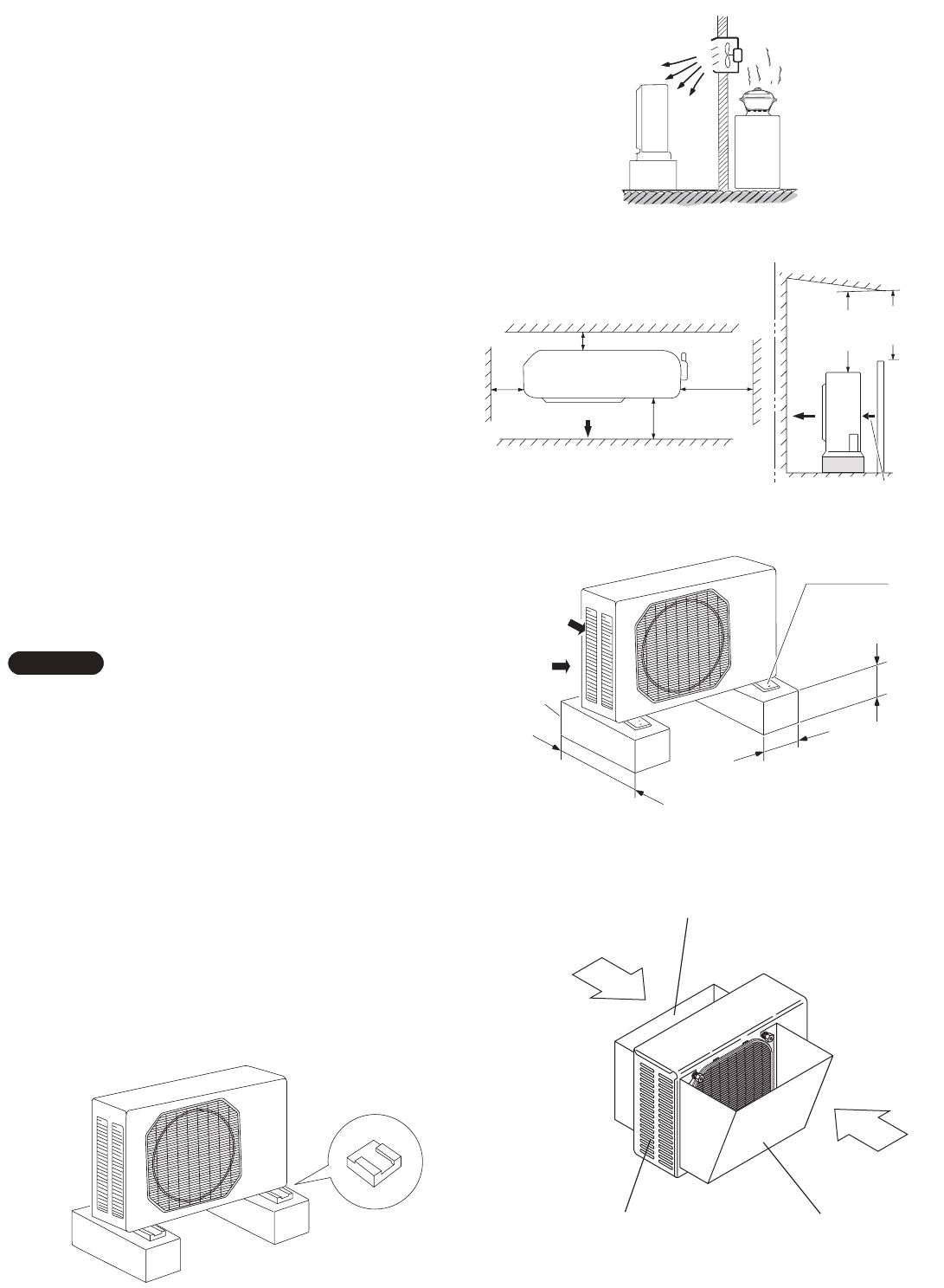
2-2. Outdoor Unit
AVOID:
Gheat sources, exhaust fans, etc. (Fig. 4)
Gdamp, humid or uneven locations.
DO:
Gchoose a place as cool as possible.
Gchoose a place that is well ventilated.
Gallow enough room around the unit for air intake/
exhaust and possible maintenance. (Fig. 5a)
Gprovide a solid base (level concrete pad, concrete
block, 4" ×1'4" (10 ×40 cm) beams or equal), a mini-
mum of 4" (10 cm) above ground level to reduce
humidity and protect the unit against possible water
damage and decreased service life. (Fig. 5b)
GInstall cushion rubber under unit’s feet to reduce
vibration and noise. (Fig. 5c)
Guse lug bolts or equal to bolt down unit, reducing
vibration and noise.
GInstall in a location where no antenna of a television
or radio exists within 10' (3 m).
2-3. Baffle Plate for the Outdoor Unit
(CLxx models only)
It is recommended to use baffle plates for models
CL0971 and CL1271. The baffle plates are not normally
required for the other models.
When the outdoor unit is installed in a position exposed
to strong wind (such as seasonal winds with low air tem-
perature in winter), baffle plates must be installed on the
outdoor unit. (Fig. 5d)
This unit is designed so that the fan of the outdoor unit
runs at low speed when the air conditioner is operated at
low outdoor air temperatures. When the outdoor unit is
exposed to strong wind, the system pressure drops
because of the freeze protector.
Install a pair of windbaffle plates at the front and back of
the outdoor unit if it will be subject to strong wind during
the winter. (Figs. 5d, 5e, 5f, 5g, and 5h)
NOTE
Outdoor unit
Hot air
Heat source
Exhaust fan
NO
Fig. 5a
Air intake Min. 2" (5 cm)
Air discharge
Min.
2" (5 cm) Min.
8" (20 cm)
Valve
side
Min. 10"
(25 cm)
Min.
7' (2 m)
Min.
7' (2 m)
Ground
Obstacle
Obstacle above
Air discharge
Min. 2" (5 cm)
Air intake
Air intake
Concrete
or equal
About 4" (10 cm)
Min. 4" (10 cm)
Anchor bolts
(4 pcs.)
About 16" (40 cm)
Cushion rubber
Air intake baffle
Air discharge baffleNo air intake baffle
required on
this side.
Wind
Wind
Back
Front
Fig. 4
Fig. 5b
Fig. 5c Fig. 5d
5
07-105 KS0971-1271 5/10/07 9:17 AM Page 5
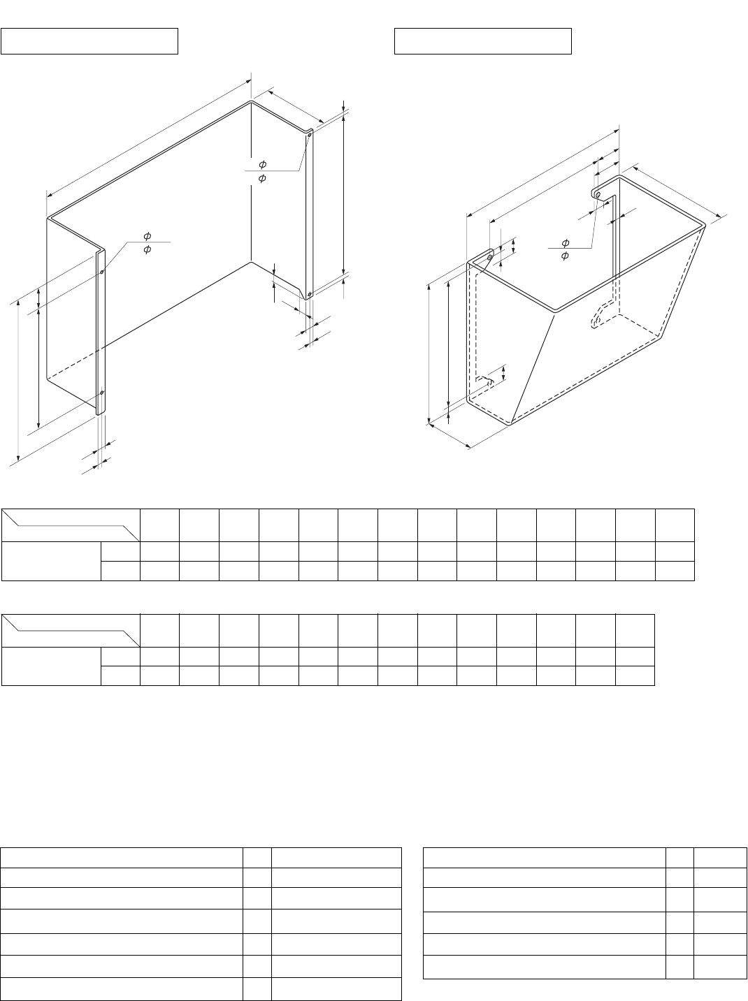
6
(1) Recommended dimensions of the baffle plates
D
E
C
J
H
K
G
B
I
P
Q
A
F
N
(2- 6.5 mm)
2- 1/4"
(2- 6 mm)
2- 15/64"
A
B
HC
E
F
G
G
M
L
K
I
J
D
(4- 6.5 mm)
4- 1/4"
Fig. 5f
For Air Intake
For Air Discharge
Material to be used: Metal plate with corrosion protection treatment
Plate thickness: 0.0394 to 0.0472" (1.0 to 1.2 mm)
(2) Parts required (field supply except for screws)
Dimensions ABCDEFGH I JKNPQ
Model
CL0971, CL1271 (inch)
21-21/32
25/32 2-5/32 17-5/16 13 25/64 19/32 23/64 19/64 17-3/8 25/64 5-29/32 25/32 25/32
(mm) 550 20 55 440 330 10 15 9 7.5 441 10 150 20 20
Dimensions ABCDEFGH I JKLM
Model
CL0971, CL1271 (inch)
19-3/32 20-3/32
13-25/32
5-29/32
17-17/32
25/32 2-5/32 14-9/16 2-3/4 3-11/32 19/32 1-3/8 1-3/8
(mm) 485 510 350 150 445 20 55 370 70 85 15 35 35
Air Intake Baffle Air Discharge Baffle
Fig. 5e
Item Q’ty Remarks
Baffle plate 1
Screw 5/32 ×15/32" (4 ×12 mm) tapping 2 Attached to outdoor unit
Bolt 15/64 ×19/32 – 25/32" (M6 ×15 – 20 mm) 2
Nut 15/64" (M6) 2
Washer 2
Spring washer 2
Item Q’ty Remarks
Baffle plate 1
Bolt 15/64 ×13/32 – 19/32" (M6 ×10 – 15 mm) 4
Nut 15/64" (M6) 4
Washer 4
Spring washer 4
Air Intake Baffle Air Discharge Baffle
07-105 KS0971-1271 5/10/07 9:17 AM Page 6
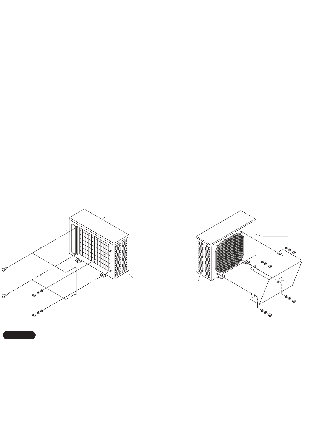
7
(3) Installation procedure
Panel front
Panel side R
Panel side L
GIn order to prevent contact of the bolts and heat exchanger and other parts inside the unit, install the windbaffle using
bolts from inside the unit and fasten the bolts with nuts from outside the unit.
GWhen the windbaffle is installed on the unit, the unit has higher wind resistance. In order to prevent the unit from
falling over, anchor the legs of the unit using anchor bolts (or similar method).
NOTE
Fig. 5g Fig. 5h
2. Air Discharge Baffle
1. Remove the panels front, side L and R from the unit
and drill 4 holes of ø1/4 inch (6.5 mm) at the
prescribed positions.
2. Install the windbaffle on the unit using field supply
bolts and nuts.
3. Recommended bolts to be used are 15/64" (M6 ISO
standard), and the recommended length of the bolts
is between 13/32 – 19/32 inch (10 – 15 mm).
4. Use washers and spring washers to tightly fasten the
windbaffle to the unit.
(4) Precautions for installation
1. Be sure not to damage painted surfaces.
2. Finish the edges of the windbaffle to avoid cuts or injury.
3. Drilling of holes must be carefully done so that no damage is caused to external or internal parts of the unit.
Particular care must be taken that drill chips do not drop into the unit.
Panel front
Panel side R
Panel side L
1. Air Intake Baffle
(1) Left side
1. Remove the front panel from the unit.
2. Remove the panel side L, and drill 2 holes of ø1/4 inch
(6.5 mm) at the prescribed position.
3. Install the windbaffle on the unit using field supply bolts
and nuts.
4. Recommended bolts to be used are 15/64" (M6 ISO
standard), and the recommended length of the bolts is
between 19/32 – 25/32 inch (15 – 20 mm).
5. Use washers and spring washers to tightly fasten the
windbaffle to the unit.
(2) Right side
1. Remove the front panel from the unit.
2. Use 2 preholes on the panel side R to install the baffle
plate.
3. Remove the panel side R from the unit by removing the
screws. These screws are used in step 4 below.
4. Put (sandwich) the windbaffle between the unit and the
panel side R, then install the windbaffle on the unit using
the above screws. Be careful not to damage the screw
holes.
07-105 KS0971-1271 5/10/07 9:17 AM Page 7
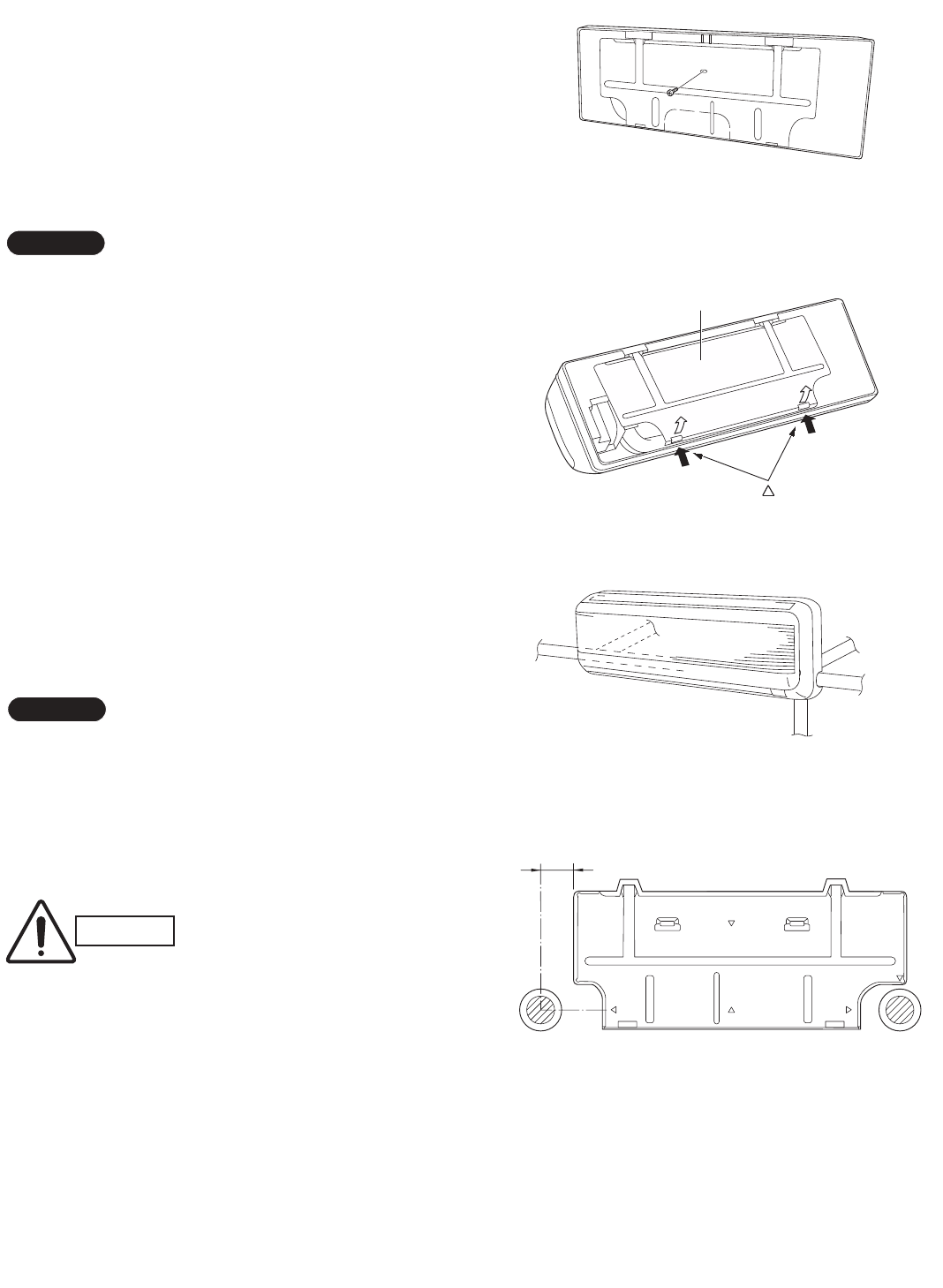
8
Set screw only for transportation
Fig. 6
Rear panel
marks
Fig. 7
Left
tubing
Right tubing
Downward tubing
Right-rear
tubing
(recommended)
Left-rear
tubing
Fig. 8
3. How to Install the Indoor Unit
3-1. Remove the Rear Panel from the Unit
(1) Remove and discard the set screw on the rear
panel. (Fig. 6)
(2) Press the 2 LLmarks on the frame cover and disen-
gage the stationary tabs from the frame. (Fig. 7)
(3) Remove the rear panel.
Tubing can be extended in 5 directions as shown in Fig.
8. Select the direction you need providing the shortest
run to the outside unit.
GWhen left tubing is to be done, switch the drain hose
and drain cap. (For details, refer to “Switching drain
hose and drain cap” on page 16.)
3-2. Make a Hole
(1) Place the rear panel from the indoor unit on the wall
at the location selected. Make sure the panel is hori-
zontal, using a carpenter’s level or tape measure to
measure down from the ceiling. Wait until after cut-
ting the hole before attaching the rear panel to the
wall.
(2) Determine which side of the unit you should make
the hole for tubing and wiring. (Fig. 9)
In the case of left-rear tubing, use the measurement
points 2-3/4" (70 mm) from the edge of the rear panel for
precise placement of the hose outlet. (Fig. 9)
(3) Before making the hole, check carefully that no
studs or pipes are directly run behind the spot to be
cut.
The above precautions are also applicable if tubing
goes through the wall in any other location.
NOTE
NOTE
2-3/4" (70 mm)
Fig. 9
CAUTION Also avoid areas where elec-
trical wiring or conduits are
located.
07-105 KS0971-1271 5/10/07 9:17 AM Page 8
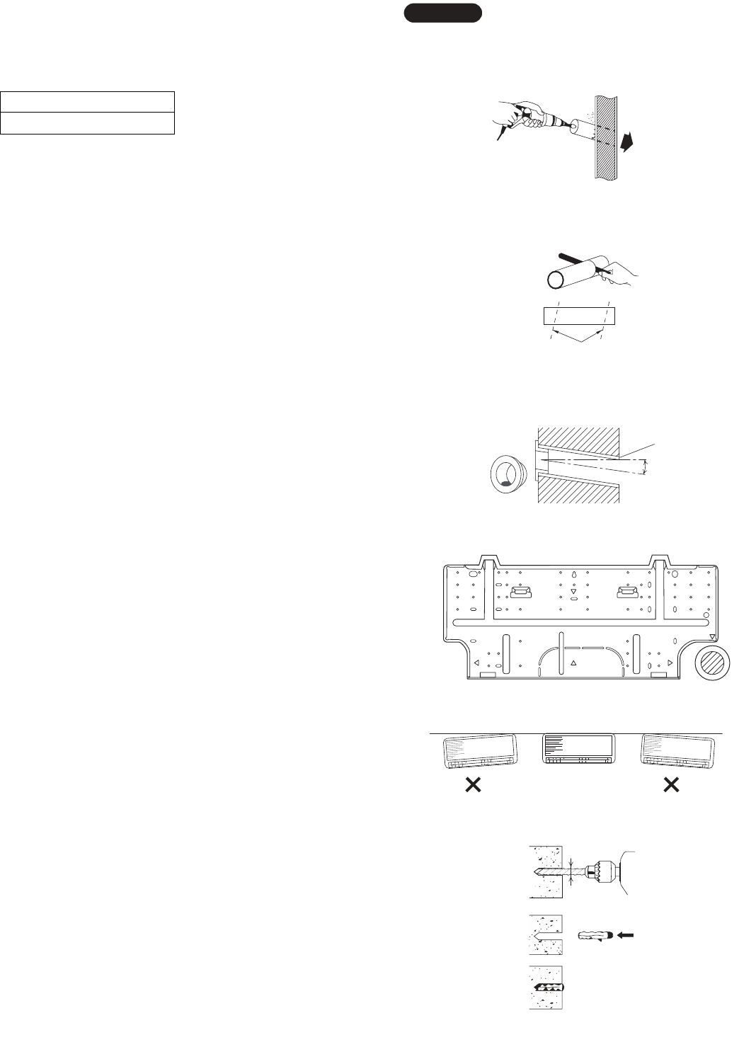
9
Indoor
side
Outdoor
side
Hole should be made at a slight downward slant to the
outdoor side.
NOTE
Fig. 10
Plastic cover
INSIDE OUTSIDE
Wall
Slight
angle
PVC pipe
(Locally purchased)
Fig. 12
PVC pipe (Locally purchased)
Cut at sli
g
ht an
g
le
Fig. 11
(4) Using a sabre saw, key hole saw or hole-cutting drill
attachment, cut a hole in the wall. See Table 4 and
Fig. 10.
Table 4
(5) Measure the thickness of the wall from the inside
edge to the outside edge and cut PVC pipe at a
slight angle 1/4" (6 mm) shorter than the thickness of
the wall. (Fig. 11)
(6) Place the plastic cover over the end of the pipe
(for indoor side only) and insert the pipe in the wall.
(Fig. 12)
3-3. Install the Rear Panel on the Wall
Be sure to confirm that the wall is strong enough to sus-
pend the unit.
See either Item a) or b) below depending on the wall type.
a) If Wooden Wall
(1) Attach the rear panel to the wall with the 8 screws
provided. (Fig. 13)
If you are not able to line up the holes in the rear
panel with the beam locations marked on the wall,
use rawl plugs or toggle bolts to go through the
holes on the panel or drill 3/16" (5 mm) dia. holes in
the panel over the stud locations and then mount the
rear panel.
(2) Double check with a carpenter’s level or tape mea-
sure that the panel is level. This is important to
install the unit properly. (Fig. 14)
(3) Make sure the panel is flush against the wall. Any
space between the wall and unit will cause noise
and vibration.
b) If Block, Brick, Concrete or Similar Type Wall
Make 3/16" (4.8 mm) dia. holes in the wall. Insert rawl
plugs for appropriate mounting screws. (Fig. 15)
Hole Dia.
2-9/16" (65 mm)
Fig. 13
Fig. 14
3/16"
(4.8 mm) dia. hole
Rawl plug
Fig. 15
07-105 KS0971-1271 5/10/07 9:17 AM Page 9
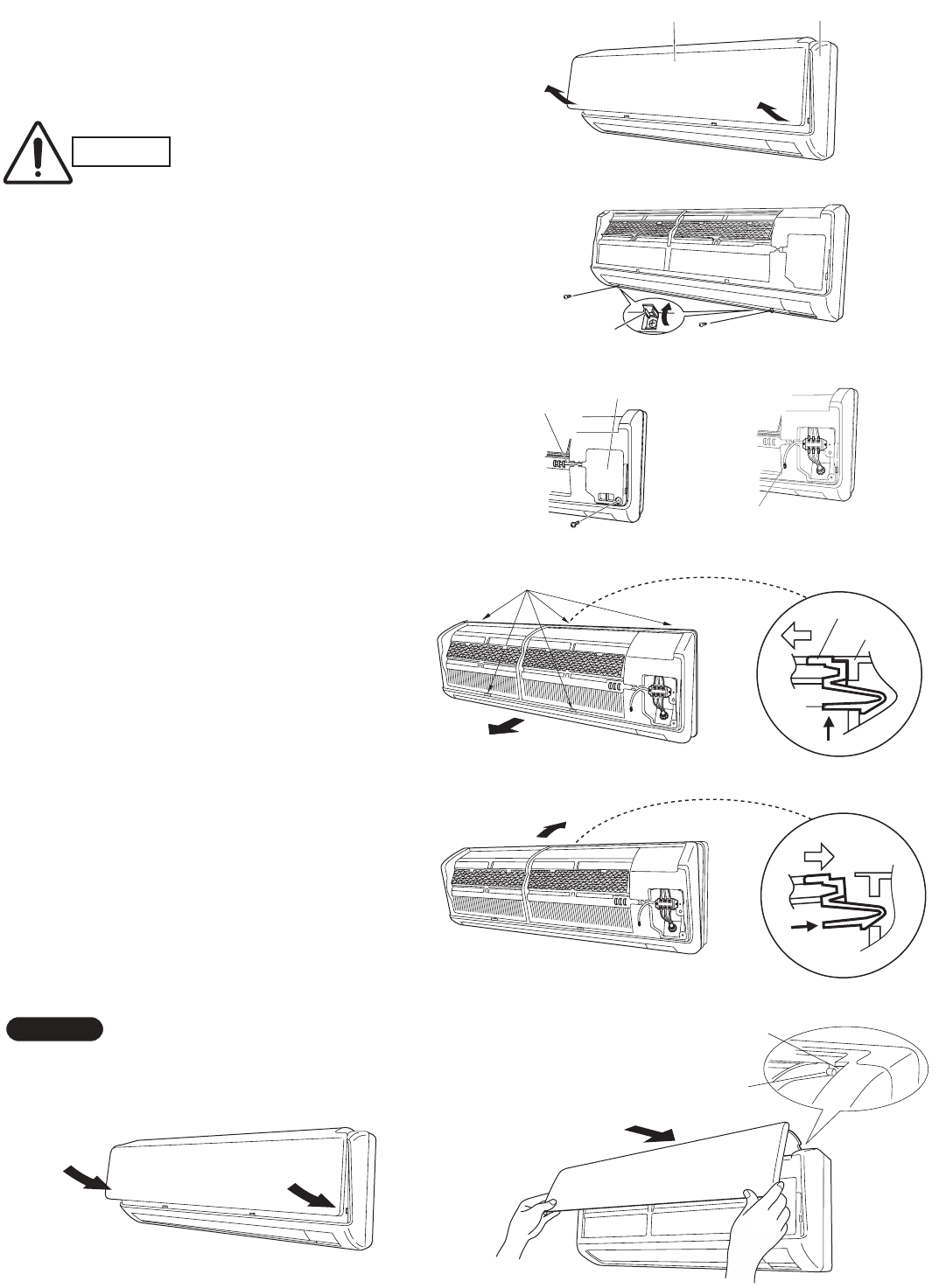
10
3-4. Remove the Grille to Install the Indoor Unit
Basically, these models can be installed and wired without
removing the grille. If access to any internal part is need-
ed, follow the steps as given below.
How to remove the grille
(1) Grasp both ends of the air intake grille, and remove it
by opening towards the front and pulling towards you.
(Fig. 16a)
(2) Remove the 2 screws. (Fig. 16b)
(3) Remove the screw on the right side cover plate and
open the cover. (Fig. 17a)
(4) Take out the thermistor from the grille. (Fig. 17b)
(5) Pull the lower part of the grille toward you to remove.
(Fig. 18a)
(6) Use a standard screwdriver to push on the tabs to
remove the grille.
How to replace the grille
(1) Reinstall the grille into the lower part while aligning
its tabs on the upper part. (Fig. 18b) Insert the
tabs in the slots and push the lower part of the
grille back into position.
(2) Make sure that the grille and frame are firmly fitted
together by engaging the tabs.
(3) Attach the thermistor on the grille. (Fig. 17a)
(4) Close the cover and replace the screw. (Fig. 17a)
(5) Affix the grille with the 2 previously removed
screws. (Fig. 16b)
(6) Install the air intake grille.
(a) Allow the edge of the air intake grille to slide into
the top of the indoor unit, and then insert it all the
way inside. (Fig. 19a)
(b) Press the bottom right and left corners of the air
intake grille to attach it to the indoor unit. (Fig. 19b)
Attach so that the round pins at the top right and left cor-
ners of the air intake grille are inserted into the grooves at
the top right and left of the indoor unit.
NOTE
Screw cover
Air intake grille Grille
Fig. 16a
Fig. 16b
Cover
Thermistor
Fig. 17a
Thermistor
Fig. 17b
Fig. 18a
Grille
Frame
Tab
Tab
*
*
Fig. 18b
*
*
Fig. 19b
Fig. 19a
Pin
Groove
CAUTION Be sure to wear work gloves
during installation to avoid being
cut by the sharp aluminum fins
of the heat exchanger.
07-105 KS0971-1271 5/10/07 9:17 AM Page 10
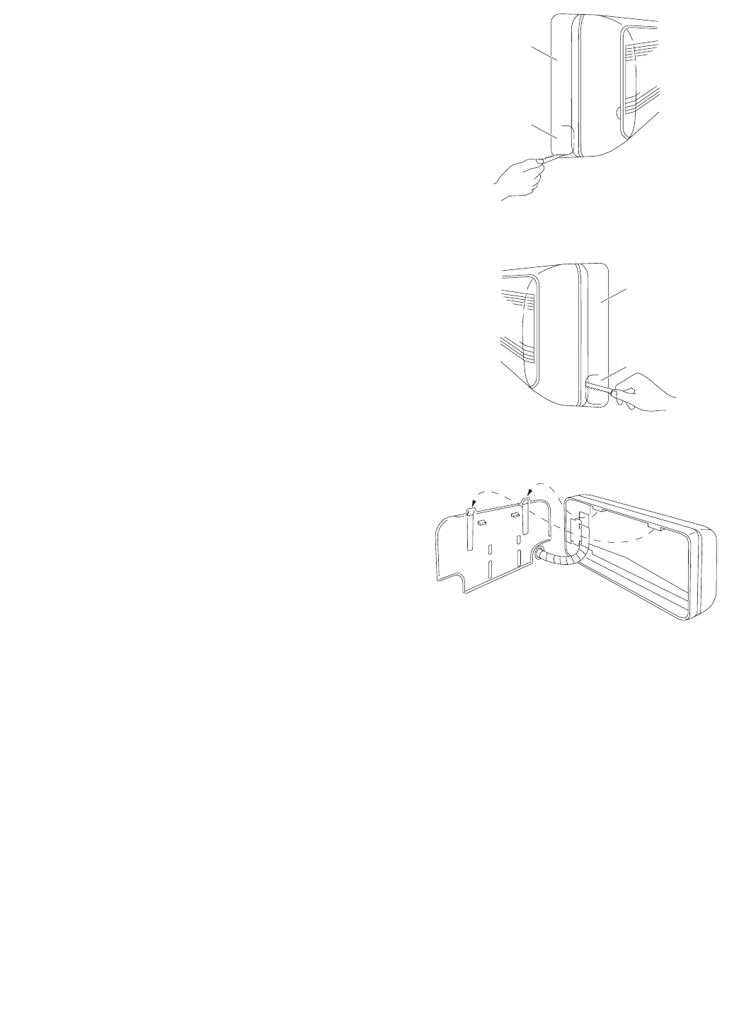
11
3-5. Shape the Indoor Side Tubing
(1) Arrangement of tubing by direction
a) Right or left tubing
Cut out the corner of the right/left frame with a
hacksaw or the like. (Figs. 20 and 21)
b) Right-rear or left-rear tubing
In this case, the corner of the frame need not be
cut.
(2) To mount the indoor unit on the rear panel:
Hang the 2 mounting slots of the unit on the
upper tabs of the rear panel. (Fig. 22)
3-6. Wiring Instructions
General precautions on wiring
(1) Before wiring, confirm the rated voltage of the unit as
shown on its nameplate, then carry out the wiring
closely following the wiring diagram.
(2) Provide a power outlet to be used exclusively for
each unit, with a power supply disconnect and cir-
cuit breaker for overcurrent protection provided in
the exclusive line.
(3) To prevent possible hazards due to insulation failure,
the unit must be grounded.
(4) Each wiring connection must be done tightly and in
accordance with the wiring system diagram. Wrong
wiring may cause the unit to misoperate or become
damaged.
(5) Do not allow wiring to touch the refrigerant tubing,
compressor, or any moving parts of the fan.
(6) Unauthorized changes in the internal wiring can be
very dangerous. The manufacturer will accept no
responsibility for any damage or misoperation that
occurs as a result of such unauthorized changes.
Frame
Right tubing
outlet
Frame
Left tubing
outlet
Fig. 21
Fig. 22
Fig. 20
07-105 KS0971-1271 5/10/07 9:17 AM Page 11
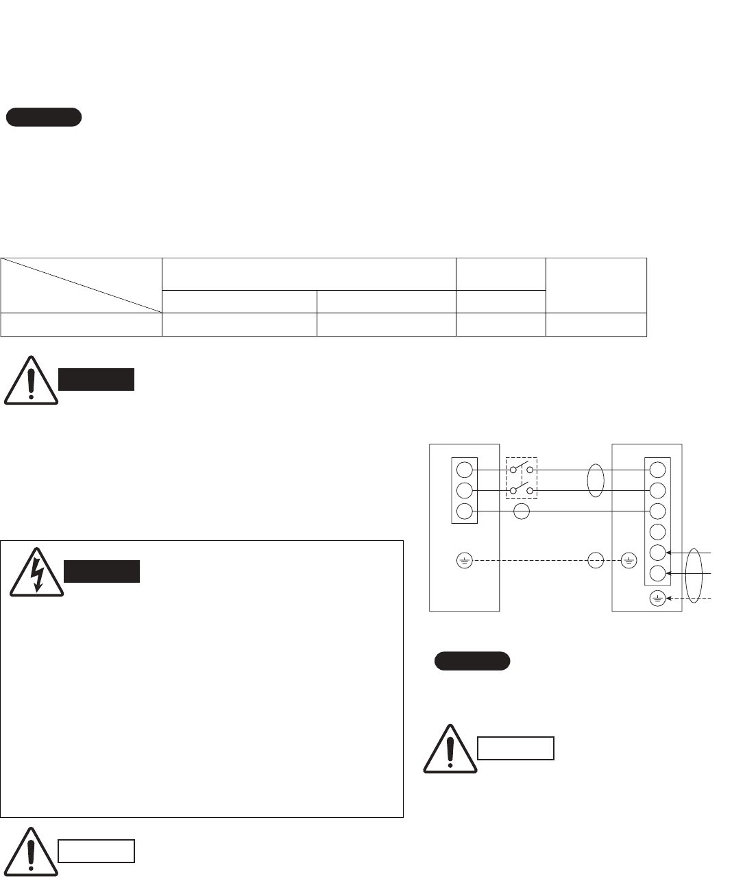
12
3-7. Recommended Wire Length and Diameter
Regulations on wiring diameter differ from locality to locality. For field wiring
requirements, please refer to your local electrical codes. Carefully observe these
regulations when carrying out the installation.
Table 5 lists recommended wire lengths and diameters for power supply systems.
Refer to the wiring system diagram (Fig. 23) for the meaning of (A), (B), and (C) in
Table 5.
Refer to your local codes or in the absence of local codes see the National Elec-
tric Code: ANSI/NFPA70.
NOTE
Fig. 23
WIRING SYSTEM DIAGRAM
GBe sure to comply with local codes on running the wire
from the indoor unit to the outdoor unit (size of wire and
wiring method, etc.).
GEach wire must be firmly connected.
GNo wire should be allowed to touch refrigerant tubing, the
compressor, or any moving part.
Disconnect
switch
1
2
3
1
2
3
4
5
6
Grounding line
115V
115V
115V
INDOOR
UNIT
OUTDOOR
UNIT
Field supply
Grounding
line
L
N
Power supply
Single phase 115V 60HZ
Te r mi nal Terminal
(A)
(B)
(C)
(B)
CAUTION
GBe sure to connect the power supply line to the outdoor unit as shown in the wiring diagram.
The indoor unit draws its power from the outdoor unit.
GDo not run wiring for antenna, signal, or power lines of television, radio, stereo, telephone,
security system, or intercom any closer than 3'4" (1 m) from the power cable and wires
between the indoor and outdoor units. Electrical noise may affect the operation.
GTo avoid the risk of electric shock, each air conditioner
unit must be grounded.
GFor the installation of a grounding device, please
observe local electrical codes.
GGrounding is necessary, especially for units using
inverter circuits, in order to release charged electricity
and electrical noise caused by high tension.
Otherwise, electrical shock may occur.
GPlace a dedicated ground more than 7' (2 m) away from
other grounds and do not have it shared with other elec-
tric appliances.
WARNING
(A)+(B) (A) Power Supply Wiring Length (ft) (C) Control Fuse or Circuit AWG (B) Power Line Length (ft) Line Length (ft)
Model (#14) (#12) (#14) Breaker Capacity
C0971, CL0971, C1271, CL1271
131 (Max.) 230 (Max.) 65 (Max.) 20A
# ... AWG (American Wire Gauge)
Table 5
WARNING
*
*
Disconnect switch may be required by national
or local codes.
NOTE
Always comply with national and local code
requirements.
CAUTION
07-105 KS0971-1271 5/10/07 9:17 AM Page 12
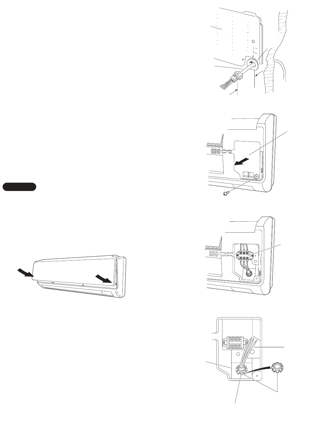
13
3-8. Wiring Instructions for Inter-unit Connections
(1) Insert the inter-unit wiring (according to local codes)
into the through-the-wall PVC pipe. Run the wiring
toward the indoor side allowing approx. 10" (25 cm)
to extend from the wall face. (Fig. 24)
(2) Grasp both ends of the air intake grille, and remove
it by opening towards the front and pulling towards
you.
(3) Remove the screw on the right side cover plate and
open the cover. (Fig. 25)
(4) Route the inter-unit wiring from the back of the
indoor unit and pull it toward the front for connec-
tion. (Fig. 26a, 26b)
(5) Connect the inter-unit wiring to the corresponding
terminals on the terminal plate (Fig. 26a, 26b) while
referring to the wiring diagram.
(6) Be sure to secure the wiring with the provided
clamp.
When closing the air intake grille, press on both corners.
(Fig. 27)
Please refer to “How to replace the grille” on page 10 for
installing the air intake grille.
NOTE
Rear
panel
Wiring
Wall
10"
(25 cm)
Plastic
cover
Fig. 24
Cover
Fig. 25
Te r mi nal
plate
Fig. 26a
Inter-unit
wiring
Lock nut
Earth
plate
Top of conduit
connector
Fig. 26b
Fig. 27
07-105 KS0971-1271 5/10/07 9:17 AM Page 13
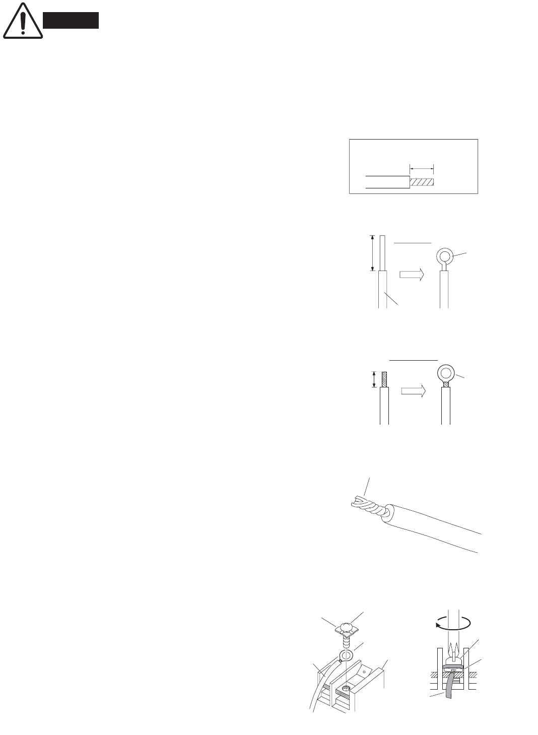
14
When connecting each power wire to the corresponding
terminal, follow the instructions “How to connect wiring
to the terminal” and fasten the wire securely tight with
the fixing screw of the terminal plate.
How to connect wiring to the terminal
a) For Indoor Unit
(1) Cut the wire end with a cutting pliers, then strip the
insulation to expose the wire about 9/32" (7 mm).
See the label (Fig. 28) near the terminal plate.
(2) Using a screwdriver, loosen the terminal screw on
the terminal plate.
(3) Insert the wire and tighten the terminal screw com-
pletely using a screwdriver.
b) For Outdoor Unit
IFor solid core wiring (or F-cable)
(1) Cut the wire end with a cutting pliers, then strip the
insulation to expose the solid wire about 15/16"
(25 mm). (Fig. 29)
(2) Using a screwdriver, remove the terminal screw(s)
on the terminal plate.
(3) Using the pliers, bend the solid wire to form a loop
suitable for the terminal screw.
(4) Shape the loop wire properly, place it on the termi-
nal plate and fix it securely with the removed termi-
nal screw using a screwdriver.
IFor stranded wiring
(1) Cut the wire end with a cutting pliers, then strip the
insulation to expose the stranded wiring about 3/8"
(10 mm) and tightly twist the wire ends. (Figs. 30
and 31)
(2) Using a screwdriver, remove the terminal screw(s)
on the terminal plate.
(3) Using a ring connector fastener or pliers, securely
clamp each stripped wire end with a ring connector.
(Fig. 30)
(4) Place the ring connector wire, and replace and
tighten the removed terminal screw using a screw-
driver. (Fig. 32)
Solid wire
Loop
Insulation
Strip 15/16" (25 mm)
Fig. 29
STRIP
SIZE
9/32"
(7 mm) (ACTUAL
SIZE)
Fig. 28
Stranded wire
Ring
connector
Strip 3/8" (10 mm)
Fig. 30
Screw
Ring connector
Terminal plate
Wire
Special
washer
Fig. 32
Screw and
special washer
Ring
connector
Wire
WARNING Loose wiring may cause the
terminal to overheat or result
in unit malfunction. A fire
hazard may also exist. There-
fore, be sure all wiring is
tightly connected.
Twist wire ends
Fig. 31
07-105 KS0971-1271 5/10/07 9:17 AM Page 14
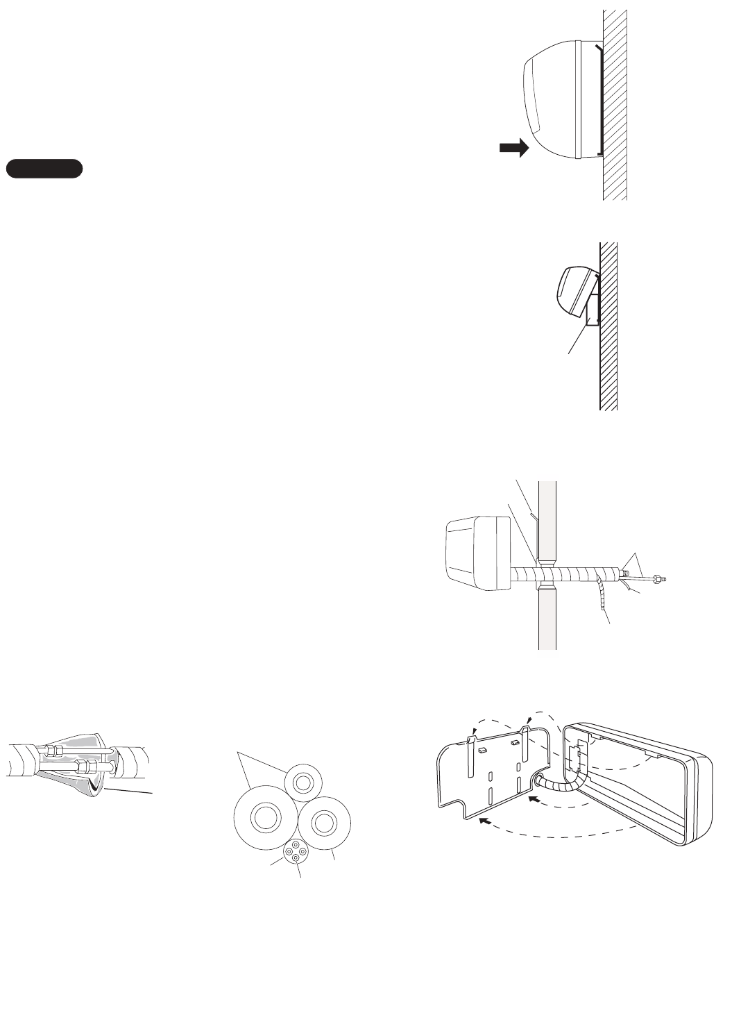
15
3-9. Mounting
(1) To install the indoor unit, mount the indoor unit onto
the 2 tabs on the upper part of the rear plate.
(2) Hold down the air discharge outlet and press the
lower part of the indoor unit until it clicks to securely
fasten to the 2 tabs on the lower part of the rear
plate. (Fig. 33)
For tubing, choose either the right or left tubing direction
and follow the steps below. This work can be made easi-
er by placing padding material (such as styrofoam) at the
rear right side of the indoor unit. (Fig. 34)
IRight-side tubing
(1) Shape the refrigerant tubing so that it can easily go
into the wall hole. (Fig. 35)
(2) Push the wiring, refrigerant tubing, and drain hose
through the hole in the wall. Adjust the indoor unit so
it is securely seated on the rear panel. (Fig. 36)
(3) Carefully bend the tubing (if necessary) to run along
the wall in the direction of the outdoor unit and then
tape as far as the fittings. (See Caution on page
20.) The drain hose should come straight down the
wall to a point where water runoff won’t stain the
wall.
(4) Connect the refrigerant tubing to the outdoor unit.
(After performing a leak test on the connecting part,
insulate it with the tubing insulation. (Fig. 37a)) Also,
refer to Section 5-4. Connecting Tubing between
Indoor and Outdoor Units.
(5) Assemble the refrigerant tubing, drain hose, and
conduit (including inter-unit wiring) as shown in
Fig. 37b.
NOTE
Cover
Refrigerant
tubing
Rear panel
Drain hose
Inter-unit
wiring
Fig. 35
Fig. 36
Fig. 33
Push
Fig. 34
Insulation
Refrigerant tubing
Drain hose
Conduit
Inter-unit wiring
Padding material
Fig. 37a
Fig. 37b
07-105 KS0971-1271 5/10/07 9:17 AM Page 15
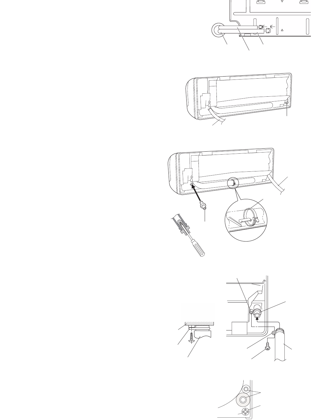
16
Hole in wall
Bent part
Narrow tube
Wide tube
Rear panel
Fig. 38
Drain cap
Drain hose
Fig. 39
ILeft-side tubing
(1) Lead the tubing and drain hose through the wall,
allowing sufficient length for connection. Then bend
the tubing using a tube bender to make the attach-
ment. (Fig. 38)
(2) Switch the drain hose and drain cap.
Switching drain hose and drain cap
(a) Locate the drain hose and the drain cap.
(Fig. 39)
(b) Remove the screws fastening the drain hose on
the right side, and pull out the drain hose to
remove it. (Fig. 39)
(c) Apply moderate force to pull off the drain cap
on the left side. (If you cannot pull it off by
hand, use a long-nose pliers.)
(d) Reattach the drain hose to the left side and the
drain cap to the right side. (Fig. 40a)
Drain hose
Slide the drain hose fully onto the drain pan outlet
until the drain hose edge is pushed into the insula-
tion. Check that the screw holes in the drain bracket
and the drain pan outlet are aligned and securely in
contact, then fasten them with the screw. (After
attaching the drain hose, check that it is attached
securely.) (Fig. 40c)
Drain cap
Use a Phillips screwdriver to push the drain cap in
firmly. (If it is difficult to push in, wet the cap with
water first.)
(3) Install the indoor unit on the rear panel.
(4) Connect the tubing and wiring led inside from out-
doors.
(5) After completing a leak test, bundle the tubing
together with armoring tape and store it inside the
tubing storage area at the back of the indoor unit
and hold it with clamps. (Figs. 40a and 41)
Fig. 40a
Fig. 40b
Fig. 40c
Fig. 41
Refrigerant tubing
Inter-unit wiring
Conduit
Screw
Drain hose
Drain pan outlet
Screw hole
Drain bracket
Drain cap
Clamp
Drain hose
Drain hose
Drain bracket
Insulation
07-105 KS0971-1271 5/10/07 9:17 AM Page 16
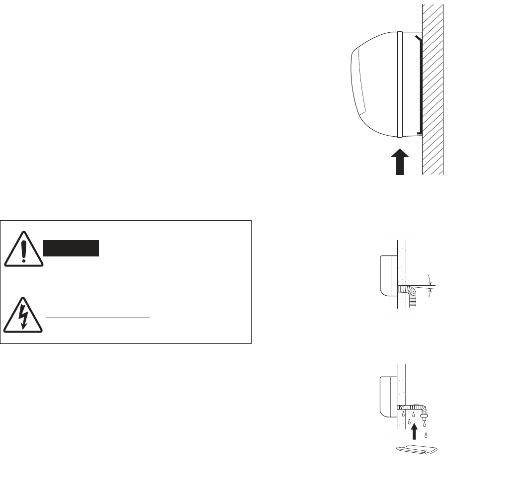
17
To unmount indoor unit
Press the 2 LLmarks on the lower part of the indoor unit
and unlatch the tabs. Then lift the indoor unit and
unmount. (Fig. 42)
3-10. Drain Hose
a) The drain hose should be slanted downward to the
outdoors. (Fig. 43)
b) Never form a trap in the course of the hose.
c) If the drain hose will run in the room, insulate the
hose with insulation*so that chilled condensation
will not damage furniture or floors. (Fig. 44)
*Foamed polyethylene or its equivalent is recom-
mended.
WARNING
Risk of Electric Shock
Do not supply power to the
unit or operate it until all
tubing and wiring to the out-
side unit are completed.
Condensation
Insulation material
(Locally purchased)
must be used.
Fig. 44
Push
Fig. 42
Slant
Drain
hose
Indoor
unit
Fig. 43
07-105 KS0971-1271 5/10/07 9:17 AM Page 17
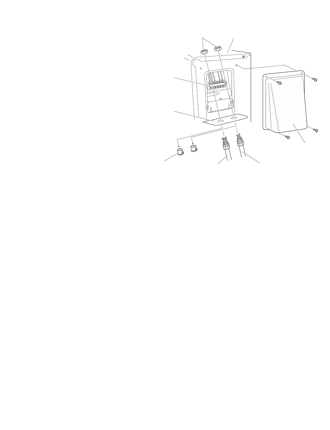
18
4. How to Install the Outdoor Unit
First refer to Section 2. Installation Site Selection.
4-1. Wiring Instructions for the Outdoor Unit
Regulations on wire size differ from locality to locality. For
field wiring requirements, please refer to your local elec-
trical codes. Make sure that the installation fully complies
with all local and national regulations.
(1) Remove access panel “C”. (Fig. 46)
(2) Connect the inter-unit and power supply line accord-
ing to the drawing on the panel side.
(3) Be sure to size each wire allowing approx. 4"
(10 cm) longer than the required length for wiring.
Store excess wiring inside the cabinet.
(4) When connections are completed, check that all
connections are correct as shown in the wiring sys-
tem diagram on panel side.
(5) Be sure to ground the unit according to your local
codes.
Lock nut
Conduit
plate
Plug Inter unit
(Conduit)
Power supply
(Conduit)
Cabinet
Te r mi nal
block
Access panel “C”
Fig. 46
07-105 KS0971-1271 5/10/07 9:17 AM Page 18
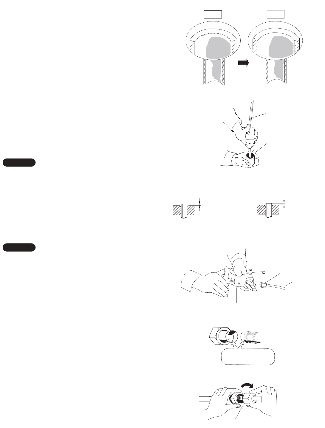
19
5. Refrigerant Tubing
5-1. Use of the Flaring Method
Many of the conventional split system air conditioners
employ the flaring method to connect refrigerant tubes
which run between indoor and outdoor units. In this
method, the copper tubes are flared at each end and
connected with flare nuts.
5-2. Flaring Procedure with a Flare Tool
(1) Cut the copper tube to the required length with a
tube cutter. It is recommended to cut approx. 12" to
20" (30 to 50 cm) longer than the tubing length you
estimate.
(2) Remove burrs at the end of the copper tube with a
tube reamer or file. This process is important and
should be done carefully to make a good flare.
(Fig. 47)
When reaming, hold the tube end downward and be
sure that no copper scraps fall into the tube. (Fig. 48)
(3) Remove the flare nut from the unit and be sure to
mount it on the copper tube.
(4) Make a flare at the end of copper tube with a flare
tool.*(Figs. 49a and 49b)
(*Use “RIGID” or equivalent.)
A good flare should have the following characteristics:
Ginside surface is glossy and smooth.
Gedge is smooth.
Gtapered sides are of uniform length.
5-3. Caution before Connecting Tubes Tightly
a) Be sure to apply a sealing cap or water-proof tape
to prevent dust or water from getting into the tubes
before they are used.
b) Be sure to apply refrigerant lubricant to the match-
ing surfaces of the flare and union before connect-
ing them together. This is effective for reducing gas
leaks. (Fig. 50)
c) For proper connection, align the union tube and
flare tube straight with each other, then screw in the
flare nut lightly at first to obtain a smooth match.
(Fig. 51)
NOTE
NOTE
Deburring
Before After
Fig. 47
Reamer
Copper
tubing
Fig. 48
Flare tool
Flare nut
Copper
tubing
Fig. 49b
Fig. 49a
Apply refrigerant
lubricant here and here
Fig. 50
Flare nut
Union
Fig. 51
0 to 0.0196"
(0 to 0.5 mm)
If the special R410A
flare tool is used:
0.0472" (1.2 mm)
If the previous flare tool
(clutch-type) is used:
Adjust so that the amount of tube
protrusion is as shown in the figure.
07-105 KS0971-1271 5/10/07 9:17 AM Page 19
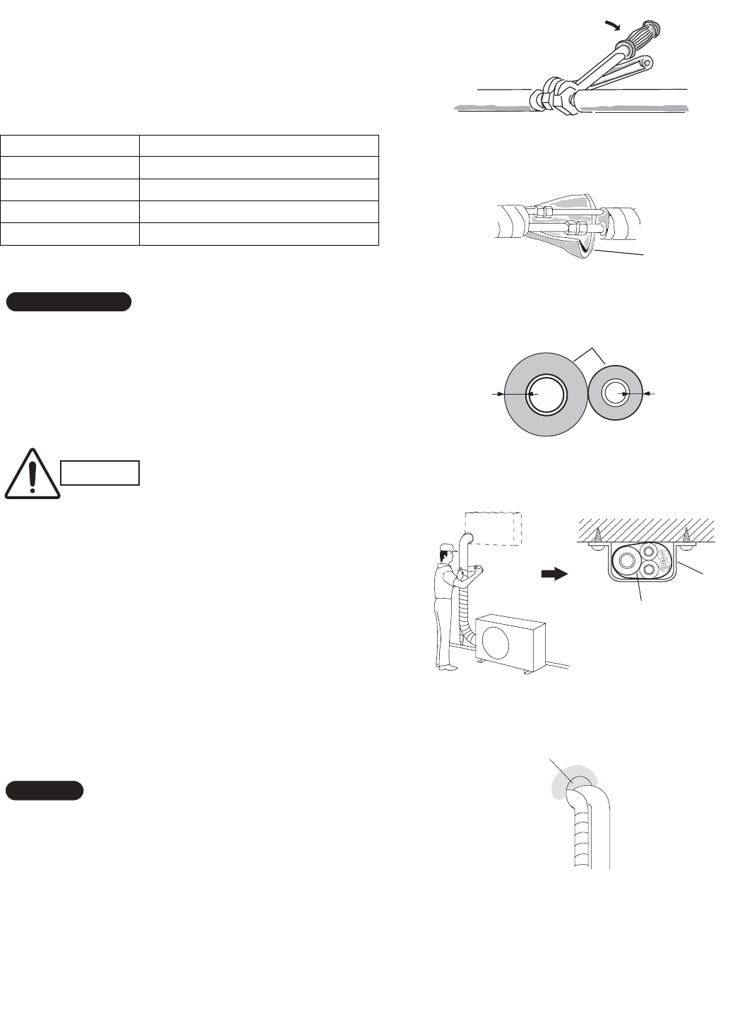
20
5-4. Connecting Tubing between Indoor and
Outdoor Units
a) Tightly connect the indoor side refrigerant tubing exten-
ded from the wall with the outdoor side tubing. (Fig. 52)
b) To fasten the flare nuts, apply specified torque as:
Table 6
5-5. Insulation of Refrigerant Tubing
To prevent heat loss and wet floors due to dripping of con-
densation, both tubes must be well insulated with a
proper insulation material. (Fig. 53)
The thickness of the insulation should be a minimum 5/16"
(8 mm). (Fig. 54)
5-6. Taping the Tubes
(1) At this time, the 2 refrigerant tubes (and electrical wire
if local codes permit) should be taped together with
armoring tape. The drain hose may also be included
and taped together as 1 bundle with the tubing.
(2) Wrap the armoring tape from the bottom of the outdoor
unit to the top of the tubing where it enters the wall. As
you wrap the tubing, overlap half of each previous tape
turn. (Fig. 55)
(3) Clamp the tubing bundle to wall, using 1 clamp approx.
every 47" (120 cm).
Do not wind the armoring tape too tightly, since this will
decrease the heat insulation effect. Also, be sure the con-
densation drain hose splits away from the bundle and drips
clear of the unit and the tubing.
5-7. Finishing the Installation
After finishing insulating and taping over the tubing, use
sealing putty to seal off the hole in the wall to prevent rain
and draft from entering. (Fig. 56)
NOTE
IMPORTANT
Indoor unit
Outdoor unit
Spanner
Torque wrench
Fig. 52
Insulation
Min.
5/16"
(8 mm)
Thickness:
min. 5/16"
(8 mm)
Fig. 54
Fig. 55
Clamp
Insulated tubes
Apply putty here
Tubing
Fig. 56
CAUTION After a tube has been insulat-
ed, never try to bend it into a
narrow curve, as this may
cause the tube to break or
crack.
Insulation
Fig. 53
Tube Dia. Tightening Torque
1/4" (6.35 mm) Approx. 120 – 160 lbs·in (140 – 180 kgf·cm)
3/8" (9.52 mm) Approx. 300 – 360 lbs·in (340 – 420 kgf·cm)
1/2" (12.70 mm) Approx. 430 – 540 lbs·in (490 – 610 kgf·cm)
5/8" (15.88 mm) Approx. 590 – 710 lbs·in (680 – 820 kgf·cm)
07-105 KS0971-1271 5/10/07 9:17 AM Page 20
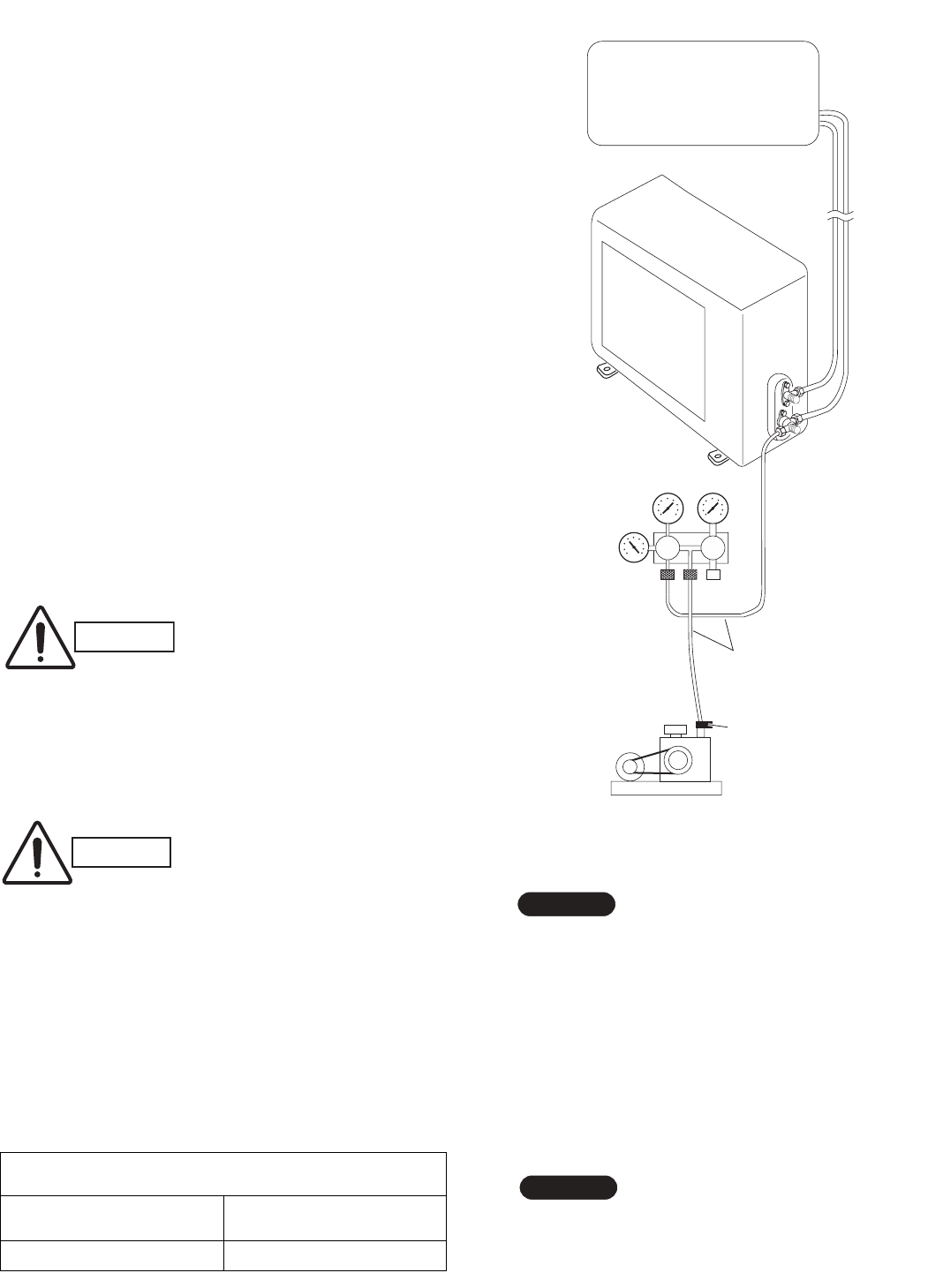
21
6. Air Purging
Air and moisture remaining in the refrigerant system
have undesirable effects as indicated below. Therefore,
they must be purged completely.
Gpressure in the system rises
Goperating current rises
Gcooling (or heating) efficiency drops
Gmoisture in the air may freeze and block capillary tubing
Gwater may lead to corrosion of parts in the refrigerant
system
IAir Purging with a Vacuum Pump (for Test Run)
(1) Check that each tube (both narrow and wide tubes)
between the indoor and outdoor units have been
properly connected and all wiring for the test run
has been completed. Note that both narrow and
wide tube service valves on the outdoor unit are
kept closed at this stage.
(2) Using an adjustable wrench or box wrench, remove
the valve caps from the service valve on both nar-
row and wide tubes.
(3) Connect a vacuum pump and a manifold valve (with
pressure gauges) to the service port on the wide
tube service valve. (Fig. 57)
(4) With the “Lo” knob of the manifold valve open, run
the vacuum pump. The operation time for the vacu-
um pump varies with tubing length and the capacity
of the pump. The following table shows the amount
of time for evacuation:
Table 7
HiLo
Indoor unit
Outdoor unit
Manifold valve
(Exclusively for R410A)
Pressure
gauge
Vacuum pump
Charging hose
(Exclusively for R410A)
Vacuum pump adapter
(Exclusively for R410A)
(with reverse flow prevention)
Fig. 57
CAUTION Be sure to use a manifold valve
for air purging. If it is not avail-
able, use a stop valve (field sup-
ply) for this purpose. The “Hi”
knob of the manifold valve must
always be kept closed.
The required time in Table 7 is calculated based on the
assumption that the ideal (or target) vacuum condition
is around 10 mmHg abs.
NOTE
Required time for evacuation when
100 liter/h vacuum pump is used
If tubing length is If tubing length is
less than 33 ft. (10 m) more than 33 ft. (10 m)
10 min. or more 15 min. or more
CAUTION
The service port on the wide tube
service valve uses a Schrader core
valve to access the refrigerant sys-
tem. The valve core is similar to
those used in automobile tires.
Therefore, be sure to use a vacuum
hose connector which has a push-
pin inside.
To prevent other refrigerants from being mistakenly
charged to units which use R410A, the size of the
charge port on the service valve is different from the
one for other refrigerant types. For servicing such as
recharging, the specified charging hose, manifold and
vacuum pump adapter (with reverse flow prevention)
for R410A must be used.
NOTE
07-105 KS0971-1271 5/10/07 9:17 AM Page 21
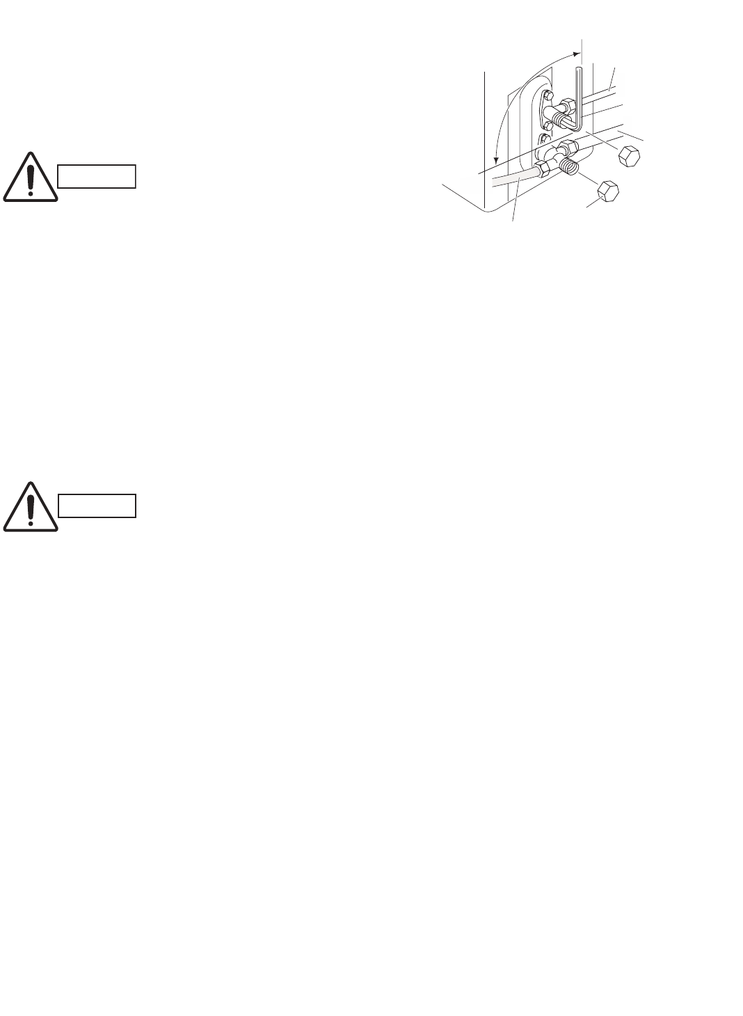
22
(5) With the vacuum pump still running, close the “Lo”
knob of the manifold valve. Then stop the vacuum
pump.
(6) With the accessory hex wrench, turn the valve stem
on the narrow tube service valve counter-clockwise
by 90 degrees (1/4 turn) for 10 seconds, and then
turn the stem clockwise to close it again. (Fig. 58)
(7) Leak test all joints at the tubing (both indoor and out-
doors) with soapy water. Bubbles indicate a leak. Tight-
en the joint more when leaks, then check if there is no
leak. Be sure to wipe off the soap with a clean cloth.
(8) With the hex wrench, turn the wide tube service
valve stem counter-clockwise to fully open the valve.
(9) Turn the narrow tube service valve stem counter-
clockwise to fully open the valve.
(10) Loosen the vacuum hose connected to the wide
tube service port slightly to release the pressure.
Then, remove the hose.
(11) Fasten the valve cap on the wide tube service port
securely with an adjustable wrench or box wrench.
Next, mount the valve cap on the service valve and
tighten it to 170 lbs·in (200 kgf·cm) with a torque
wrench. This process is very important to prevent
gas from leaking from the system.
(12) Test run the air conditioner. (See next page.)
(13) While the air conditioner is running, apply liquid
soap to check for any gas leaks around the service
valves or caps.
(14) If there is no leakage, stop the air conditioner.
(15) Wipe off the soap on the tubing.
This completes air purging with a vacuum pump and the
air conditioner is ready for actual operation.
CAUTION Be sure to completely insert
the hex wrench before
attempting to turn the valve.
Fig. 58
CAUTION This may cause the refriger-
ant gas to leak. In order to
avoid this, take off the hose
quickly.
90° (1/4 turn)Narrow tube
Hex wrench
Wide tube
Valve cap
Vacuum hose to manifold valve
07-105 KS0971-1271 5/10/07 9:17 AM Page 22
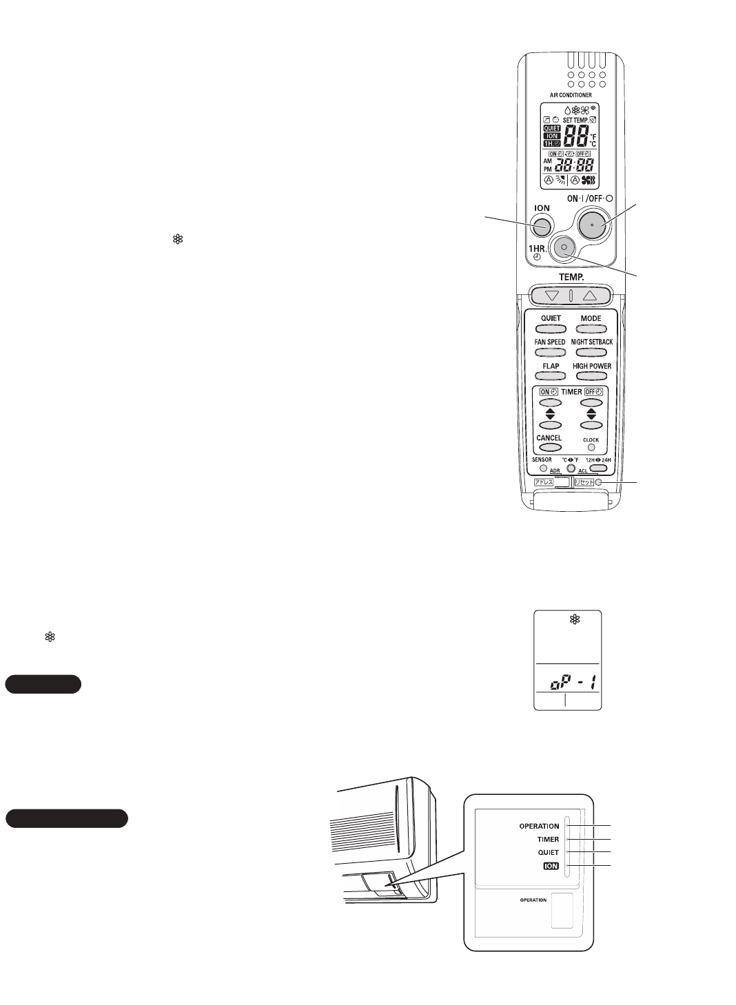
23
How to Test Run the Air Conditioner
After turning on power to the air conditioner, use the remote
controller and follow the steps below to conduct the test run.
(1) Set the remote controller in Test Run mode.
(Fig. 59a)
a) Press and hold the ION button.
b) Then press and hold the 1HR TIMER button.
c) At the same time, press the ACL (reset) button once.
Use a pointed object such as the tip of a pen to press
the ACL button.
• After a few seconds, “ ” appears and “oP-1” blinks in
the remote controller display area.
(Fig. 59b)
d) Release the 1HR TIMER button.
e) Release the ION button.
(2) Start Cooling mode test run by pressing the ON/OFF
operation button of the remote controller. (Fig. 59a)
• This starts the fan producing uncooled forced air with
the 4 indicator lamps (OPERATION lamp, TIMER
lamp, QUIET lamp, and ION lamp) on the main unit
blinking. (Fig. 59c)
• After 3 minutes, the system shifts into cooling opera-
tion, and cool air will start to be felt. Cool mode test
run is unaffected by the room temperature.
(3) Press the ON/OFF operation button of the remote con-
troller again to stop the test run. (Fig. 59a)
(4) Finally press the ACL (reset) button of the remote con-
troller to release it from Test Run mode to return to nor-
mal mode. (Fig. 59a)
• “ ” and “oP-1” will disappear from the remote con-
troller display area.
Troubleshooting:
In the event that the green “Operation Light” is blinking
upon powering up the system, an error condition exists.
In this case, refer to the self-diagnostics procedure
on the inside of the front cover.
After the test run is completed, be sure to press the
ACL (reset) button to return to normal mode. The
air conditioner will not operate correctly if this is not
done.
IMPORTANT
NOTE
Fig. 59a
Fig. 59b
Fig. 59c
A
1HR.
TIMER
ON/OFF
operation
ACL
(Reset)
ION
button
button
button
button
OPERATION lamp
TIMER lamp
QUIET lamp
ION lamp
07-105 KS0971-1271 5/10/07 9:17 AM Page 23
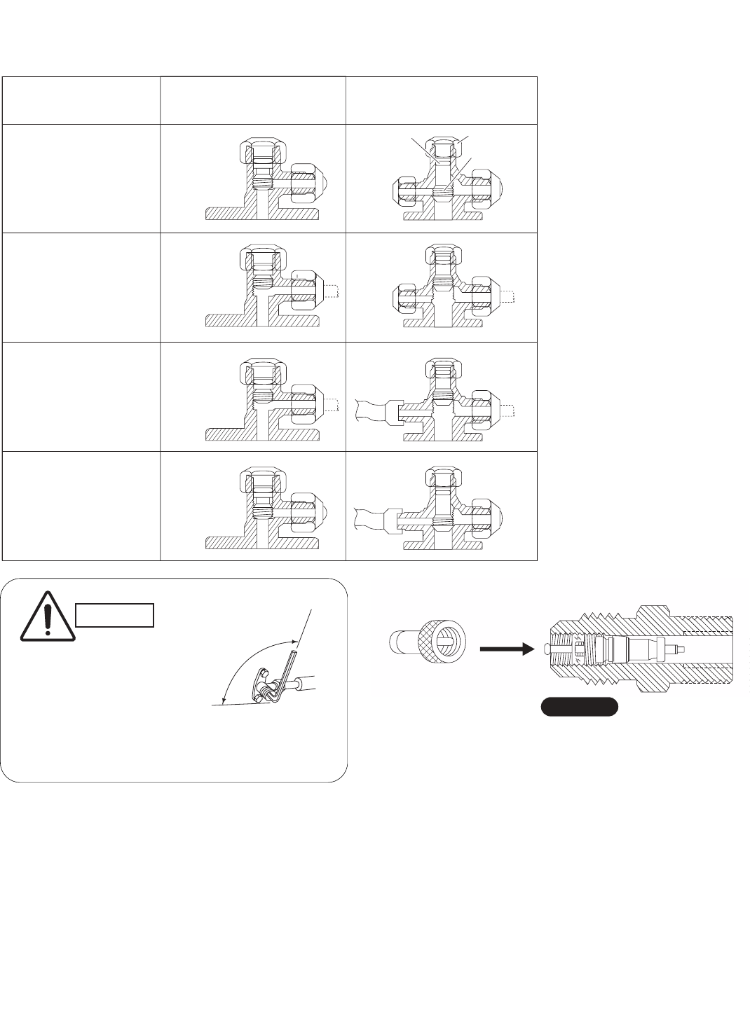
24
IPump Down
Pump down means collecting all refrigerant gas in the
system back into the outdoor unit without losing any of
the gas. Pump down is used when the unit is to be
moved or before servicing the refrigerant circuit.
Pump Down Procedure
Be sure to carry out pump down with the unit in
cooling mode.
(1) Connect the Lo side charging hose of the manifold
valve to the service port on the wide tube service
valve.
(2) Using a hex wrench, turn the narrow tube service
valve clockwise all the way to close the service
valve. (Be sure to confirm that the wide tube service
valve is fully open.)
(3) Press the operation button and start cooling oper-
ation.
(4) When the low pressure gauge reading falls to 14.2 to
7.1 psi (1 to 0.5 kg/cm2), fully close the wide tube
valve stem. Then quickly stop the unit.
(5) Disconnect all gauges and hoses, and replace the
valve caps as they were before.
IBasic Functions of the Service Valves
The basic functions of the service valves are given in Table 8 below.
Action Narrow Tube Service
Valve (2-Way)
Wide Tube Service
Valve (3-Way)
CLOSED
Fully OPEN
Fully OPEN
Shipping
Operating and
test running
the air conditioner
Measuring pressure
and gas charging
Air purging with
a vacuum pump
CLOSED
Valve cap
Stem
O-ring
*
*
Table 8
*The service port on the wide tube ser-
vice valve uses a Schrader core valve
to access the refrigerant system.
Therefore, be sure to use a hose con-
nector which has a push-pin inside.
(Fig. 60a)
PUSH
Hose with push-pin
Service valve
Fig. 60a
Close
Hex
wrench
Open
Fig. 60b
CAUTION
When opening or clos-
ing the service valve
stem, use the accessory
hex wrench. Be sure to
fully seat the wrench
before turning the valve.
External diameter of service port
R410A: 5/16"
NOTE
07-105 KS0971-1271 5/10/07 9:17 AM Page 24
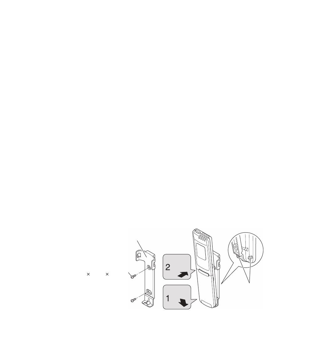
25
7. Remote Control Unit Installation Position
The remote control unit can be operated from either a
non-fixed position or a wall-mounted position.
To ensure that the air conditioner operates correctly, do
not install the remote control unit in the following places:
GIn direct sunlight
GBehind a curtain or other place where it is covered
GMore than 26' (8 m) away from the air conditioner
GIn the path of the air conditioner’s airstream
GWhere it may become extremely hot or cold
GWhere it may be subject to electrical or magnetic
interference
GWhere there is an obstacle between the remote con-
trol unit and the air conditioner (since a check signal
is sent from the remote control unit every 5 minutes)
7-1. Mounting on a Wall
Before mounting the remote control unit, press the
ON/OFF operation button at the mounting location to
make sure that the air conditioner operates from that
location. The indoor unit should make a beeping sound
to indicate that it has received the signal.
Hole
Remote control unit mount
Mounting screws
5/32 5/8" (4 16 mm)
(Included)
Rear side
Press
Set in
place To prevent loss of the remote control
unit, you can connect the remote
control unit to the mount by passing
a string through the remote control
unit and attachment hole.
Fig. 61
To take out the remote control unit, pull it forward.
07-105 KS0971-1271 5/10/07 9:17 AM Page 25
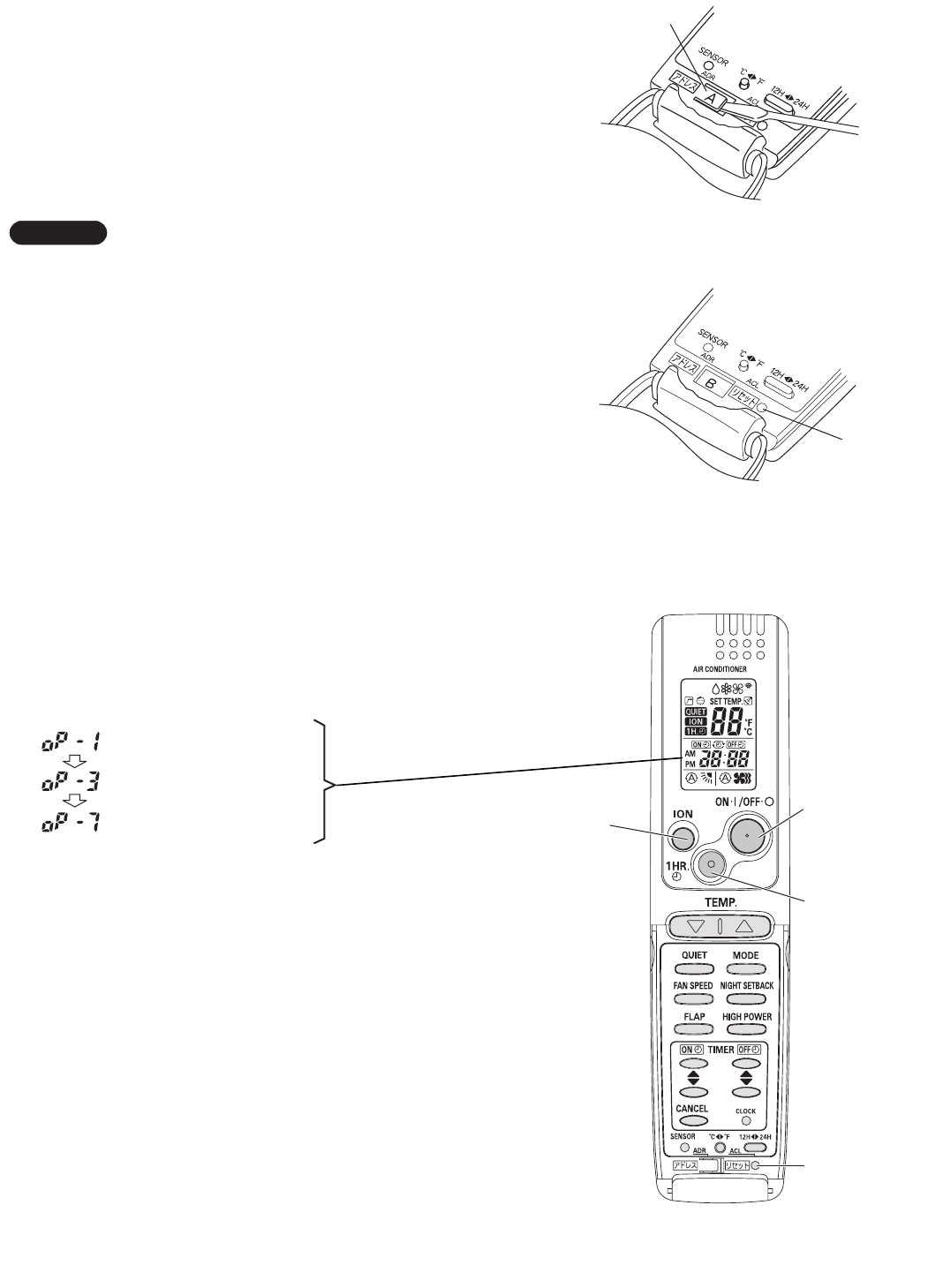
26
8. Address Switch
8-1. Address Setting of the Remote Control Unit
The address can be set in order to prevent interference
between remote controllers when two Sanyo indoor units
are installed near each other. The address is normally
set to “A.” To set a different address, it is necessary to
change the address on the second remote controller.
Once changed, you cannot restore the original address
setting of the air conditioner.
(1) Switch on the power source.
(2) Break the address-setting tab marked “A” on the
second remote controller to change the address
(Fig. 62). When the tab is removed, the address is
automatically set to B (Fig. 63).
(3) Press and hold the remote controller ION button and
1 HR TIMER button. At the same time, press the
ACL(reset) button. Use a thin object such as the tip
of a pen to press the ACL button. When this has
been done, “oP-1” (test run) appears, blinking, in the
remote controller clock display area.
(4) Each time the 1 HR TIMER button is pressed, the
display changes as shown below. Press this button
2 times to change the display to “oP-7” (address
setting). (Fig. 64)
(5) “oP-7” has now been selected for address setting.
(6) Press the ON/OFF operation button on the remote
controller. (Fig. 64) Check that the “beep”signal-
received sound is heard from the second indoor unit
(approximately 5 times). The sound you hear is the
signal that the remote controller address has been
changed.
(7) Finally press the remote controller ACL (reset) but-
ton to cancel the blinking “oP-7” display.
(Fig. 64)
Changing of the second remote controller address is
now completed.
Test run mode
Selfdiagnostic mode
Address setting mode
NOTE Fig. 62
Fig. 63
Fig. 64
Tab
ACL button
A
1HR.
TIMER
ON/OFF
operation
ACL
(Reset)
ION
button
button
button
button
07-105 KS0971-1271 5/10/07 9:17 AM Page 26
SANYO Commercial Solutions
A Division of SANYO North America Corporation
1300 Michael Drive, Suite A
Wood Dale, IL 60191, U.S.A.
Sanyo Canada Inc.
1-300 Applewood Crescent, Concord, Ontario L4K 5C7, CANADA
Jan. / 2009 (T)
