Sanyo De Users Manual
2015-01-26
: Sanyo Sanyo-De-Users-Manual-336090 sanyo-de-users-manual-336090 sanyo pdf
Open the PDF directly: View PDF ![]() .
.
Page Count: 50
SANYO Electric Co.,Ltd
SANYO Electric Trading Co.,Ltd.
Type DE (Direct-fired Chiller/Heaters)
Type NE (Steam-fired Chillers)
Type LE (Hot water-fired Chillers)
SANYO Electric Air Conditioning Co.,Ltd.
International Business Division
Overseas Sales & Marketing Dept.
1 Otsuki-Cho, Ashikaga-City,
Tochigi 326-8534, Japan
Telephone : +81-284-44-3222
Facsimile : +81-284-44-3138
http://kuchosys.sanyo.co.jp/eng/
SANYO Electric Trading Co.,Ltd.
1-10 Ueno 1-chome,Taito-ku, Tokyo 110-8534 Japan
Telephone : +81-3-3837-6266
Facsimile : +81-3-3837-6389
©2000SANYO Printed in Japan ’00 7 IM0.5
Making the World a More Comfortable Place
SANYO’s absorption technology is in evidence in
many aspects of our daily lives, from where we do
business to the places we choose to relax.
Before operating the unit
*To use the unit properly before operating, be sure to carefully read the operation manual.
*Installation should conform to regulations and laws such as Building Standard Act, Fire Laws, Air Pollution
Prevention Laws and Labor Safety and Sanitary Law, and to any other applicable regulations and laws.
On the installation
*Read the installation manual carefully before carried-in and installing the unit.
*Carried-in and works of installation, foundation, wiring, piping, interlocks and thermal insulation are involved.
Please contact your agency with any questions relating to these issues. In case such works are inadequate, it may
cause overturn, electric shock, water and fuel leakage, scalding, fire and so forth.
*Please consult your agency when the work of flue, exhaust and in-take air duct, and chimneys are required. In
case such works are inadequate, it may cause scalding, fire and oxygen deficiency.
*Waterproof work of the foundation for installing the unit and drainage ditch are required in order to prevent
wetting surrounding equipment.
*Adequate space surrounding the unit is needed for maintenance work. Such space is indispensable for safe work
and avoiding injuries.
For maintenance
*Periodical maintenance, in addition to daily inspection, is required. If it is improper in maintenance, it may cause
fire, electric shock and scalding.
*Please consult the service agency to obtain professional guidance.
Avoiding hazardous places
*Keep the units away from inflammable dangerous substance such as gasoline and thinner and erosive gas which
may result in a fire.
For the safety sake
File No. : JQ116A
Date : October 13, 1997
ISO 9001
JISZ 9901
QS Accreditation
R004
File No. : JE011A
Date : November 23, 1998
ISO 14001
JISQ 14001
EMS Accreditation
RE011
SAE-2002

1
CONTENTS
Introduction 2
Absorption cycle 11
Direct-fired chiller / heaters 15
Steam-fired chillers 43
Hot water-fired chillers 63
Utility 81
SUPER ABSORPTION
The biggest cause of environmental deterioration, such as global warming, are CO2 emissions
due to energy consumption, and countermeasures are being undertaken on a worldwide
scale.
Every effort is being made to improve the environmental situation, from an institutional level
to an individual level. Today companies are required to live in harmony with environment.
SANYO has been a leader in the field of large type absorption chillers, making use of
absorption technologies accumulated over the years, and contributes to the development
of various types of energy saving systems and improving energy systems in air conditioning
businesses.
ENVIRONMENTALLY FRIENDLY TECHNOLOGY
Keeping the nature beautiful for the future generations....
That is the common wish of the human race.
23
ENVIRONMENTALLY FRIENDLY TECHNOLOGY SUPER ABSORPTION
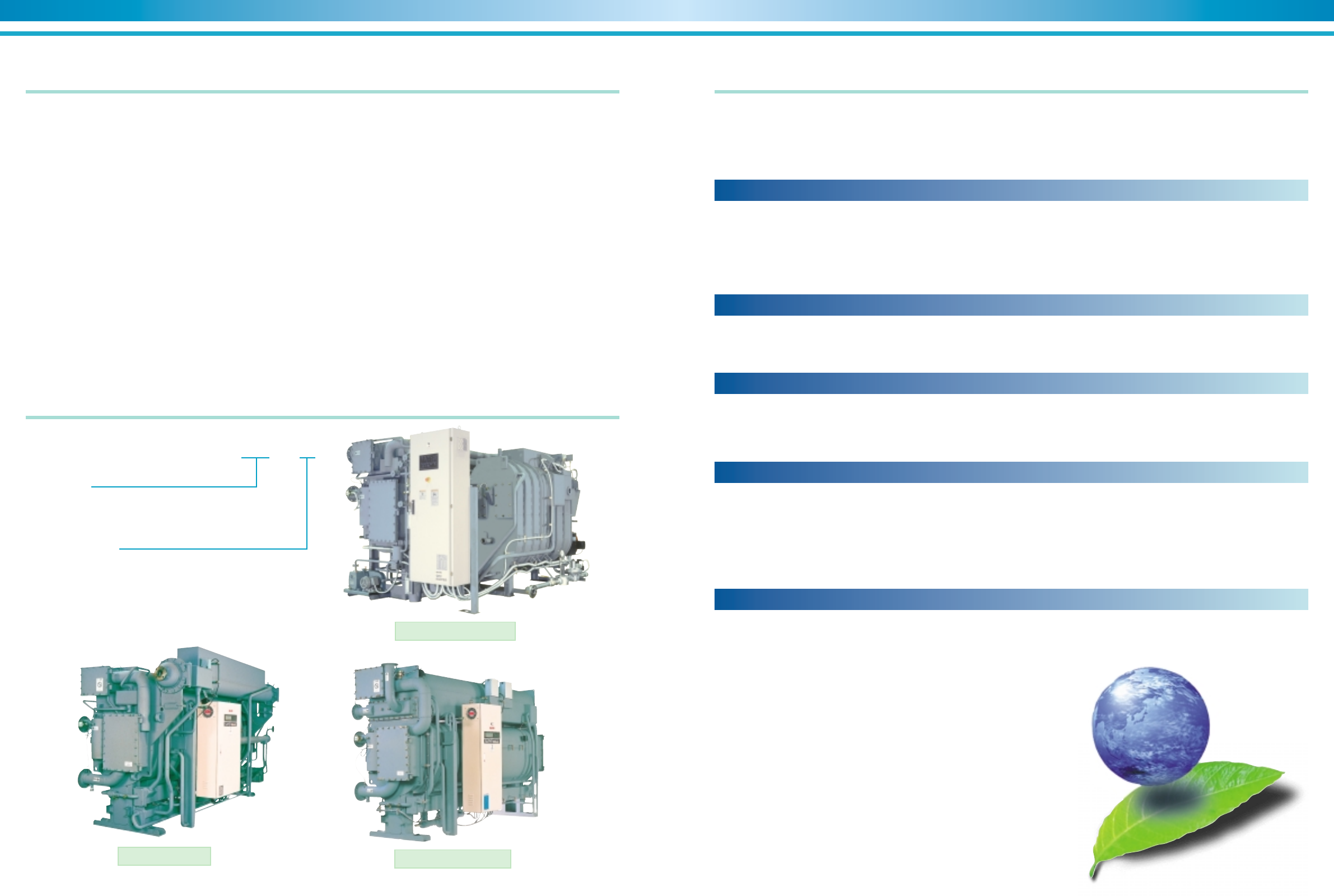
SANYO absorption chillers highlightsIntroducing the SANYO absorption chillers:
Nomenclature
TSA -- DE -- 11
Unit Type
DE=Double effect, direct-fired
NE=Double effect, steam-fired
LE=Single effect, hot water-fired
Capacity Code
SANYO, as a leading company in this field more then 20 years in domes-
tic market in Japan, now brings the high efficiency of double-effect steam
chillers and double-effect direct-fired chiller/heaters to the world market.
The SANYO absorption chillers and chiller/heaters give building owners
a better solution for many new and retrofit applications. Installation of a
direct-fired chiller/heater eliminates the need for the boiler required with
conventional installations. This reduces the initial cost of the system, mak-
ing a SANYO chillers/heaters competitive with conventional chiller/boiler
system.
The SANYO absorption chillers and chiller/heaters offer a number of other
advantages:
• Excellent for peak shaving during high electrical demand periods.
• Replaces existing inefficient single-stage absorption chillers without an
expensive electrical service upgrade.
• Has the ability to tie into district steam systems with an efficient double-
effect chiller.
• Allows diversification of critical cooling requirements. Critical cooling
loads are met with minimal electrical power input with gas or steam
fired chillers.
• Allows for smaller emergency generators to be utilized since the elec-
trical load associated with an absorption chiller is minimal when com-
pared to an electrical driven chiller.
• Ozone safe, CFC free. Cooling requirements are met without chlorine
based refrigerants.
• Reduces contribution to global warming. Minimizes global impact by
greatly reducing electricity consumption and eliminating the use of
greenhouse gases.
• Low noise and vibration. The absorption chiller does not utilize a large
motor-compressor, and this leads to quiet, trouble-free operation.
• Small footprint. The high efficiency associated with the double-effect
chiller has reduced the space required for installation.
SANYO is the industry leader in supplying compact units.
• CE marking is applicable if requested.
With the ever-changing requirements of building owners and continual
changes in building designs, SANYO introduces to the world market the
next generation of high efficiency gas and steam fired, double-effect ab-
sorption chillers.
In many parts of the world, the cost of electricity and penalties adminis-
tered through demand limits, inverted rates, time-of-day rates, ratchet
clauses, etc., have forced the need for alternative chiller systems to be
developed.
Electrical peak power shaving
By using a combination of electric driven and absorption chillers for air
conditioning loads, a central plant can take advantage of lower base elec-
tricity rates during times of high electricity demand. The absorption unit is
used to shave peak power demands during summer operation, while
operating the electric chiller below the assigned demand limit, avoiding
costly demand charges and saving money all year-round.
With the aging of the world power plants and environmental and financial
concerns blocking construction of new ones, many areas are faced with
extremely high demand charges and escalating electricity costs. In these
areas, the entire cooling load can be handled by SANYO absorption units,
allowing the allotted electricity to be used elsewhere in the building where
there are no practical alternatives.
Heating and cooling operation
With the SANYO DE direct-fired double-effect chiller/heaters, the unit
can be used for heating during winter months without additional cost of
extra controls. In many applications, the chiller/heaters can replace a
traditional electric chiller and boiler design combination, with the advan-
tage of reducing machine room floor space and giving up to 40% sav-
ings on the system start up cost in many cases.
Double effect absorption cycle
Both the steam and direct-fired SANYO chillers utilize a double-effect
absorption cycle resulting in unit COP's of 1.0 for the direct-fired chiller/
heaters and 1.2 for the steam-fired chillers. This high efficiency design
has reduced the input energy of the original single stage-absorption chill-
ers by up to 30%. SANYO's state-of-the-art double effect design has also
allowed the unit to be reduced in size as compared to previous genera-
tion units, making SANYO the industry leader in efficiency and space
utilization.
Many applications
The SANYO offers the broadest range of equipment and operating con-
ditions in the entire industry: 23 discrete unit sizes from 100 tons to 1500
tons incorporating either direct-fired or steam-fired generators. With natural
gas as one of the heat sources for direct-fired types, the customer can be
assured of a fuel that is clean burning and environmentally friendly.
The SANYO steam-fired, double-effect chiller satisfies the building owner's
need for high efficiency replacement/retrofit units plus an optimal solu-
tion to new high pressure steam chilling systems. A SANYO double-ef-
fect steam chillers is the perfect complement to a district steam heating
system, offering single source heating and cooling.
The SANYO hot water-fired chillers is applicable not only combined in
Co-generation system but utilized the waste heat as a driving heat source
in the various applications.
No CFCs
In addition to the extensive list of design benefits above, the SANYO
units are completely ozone safe/no CFC's or HCFC's.
All cooling is achieved utilizing a refrigerant with a proven track record,
ample supplies and environmentally safe: namely, water!
Additionally, since an absorption cycle is accomplished without a large
motor-compressor drive arrangement, the customer can be assured of
quiet, trouble-free, ultra-low vibration operation.
Direct-fired chiller/heaters
Hot water-fired chillers
Steam-fired chillers
45
ENVIRONMENTALLY FRIENDLY TECHNOLOGY SUPER ABSORPTION
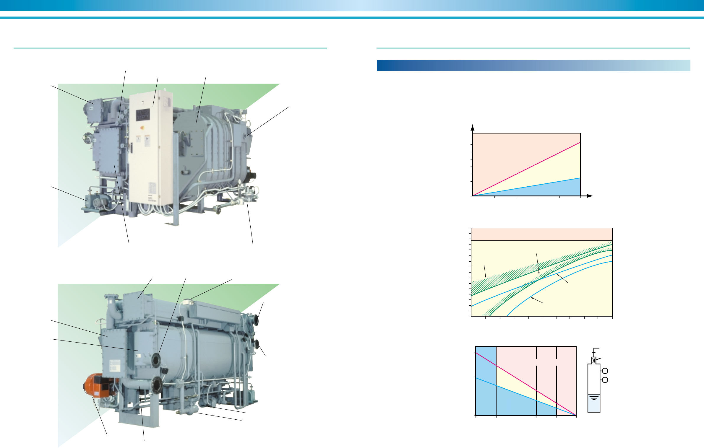
Component identification Chiller features
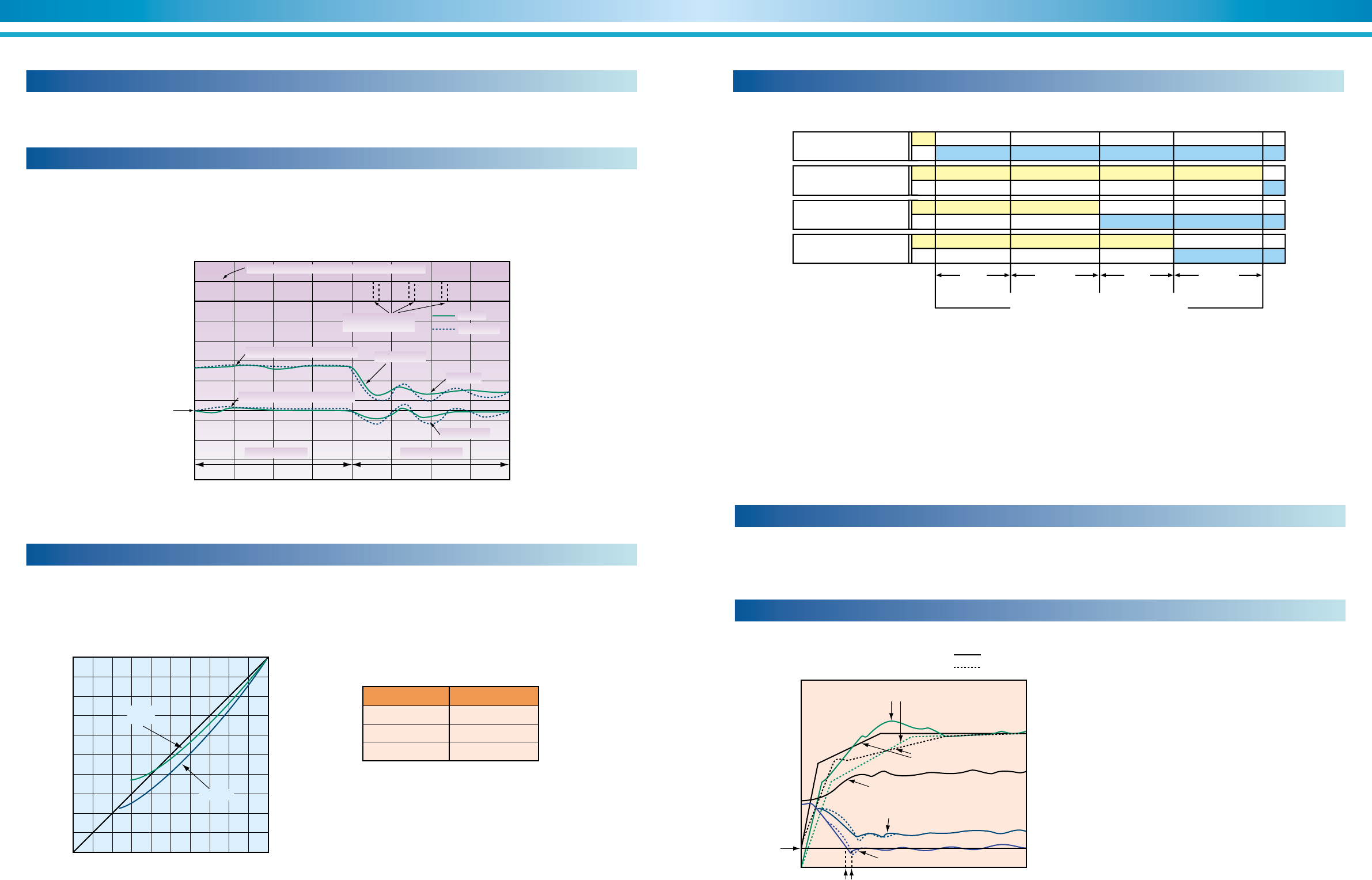
Expert function by self-diagnosis
♦♦
♦♦
♦ Prediction information
Graph 1. Fouling of heat transfer tubes in cooling water system
8
6
4
2
0020
40 60 80 100
Maintenance zone
Notice zone
Normal zone
Maintenance
judgement line
Normal line
Cooling load factor(%)
Fouling indicator
Graph 2. Tendency of absorbent concentration
8
7
6
5
4
3
2
1
0020
40 60 80 100
Abnormal stop zone
Maintenance zone
at cooling water 31°C
Normal line at
cooling water 31°C
Normal line at
cooling water 27°C
Maintenance zone
at cooling water 27°C
Cooling load factor(%)
Concentration indicator
Graph 3. Vacuum condition monitoring
1.0
0
0.6
020 60 80 100
Storage ratio(%)
Storage
tank
Pressure
sensor
Pd cell
Purge nozzle
Diluted solution
Pressure rising indicator
of storage tank
Maintenance zone
Notice
zone
Normal zone
.
Expert function is provided to monitor operating conditions, predict chiller
information and maintain stable operation.
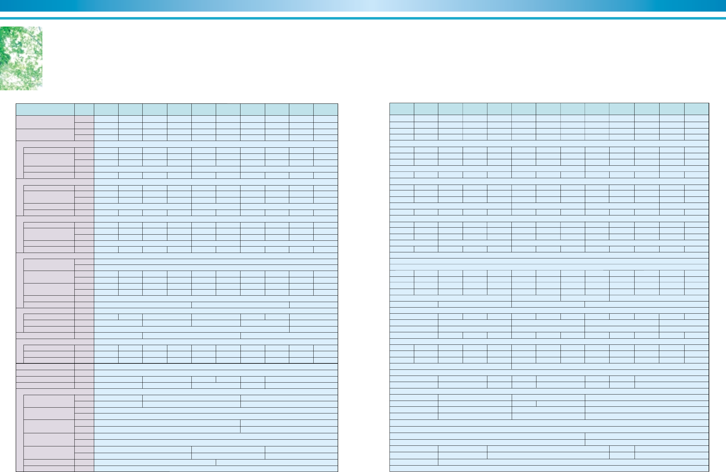
Condenser
Absorber
Evaporator
Absorber
Purge pump
Gas train
Generator
sight glass
High temperature generatorControl panel
Low temperature generator
Burner
Refrigerant pump
Absorbent pump
Chilled water outlet
Condenser Palladium cell heaterChilled water inlet
Cooling water outlet
Cooling water inlet
67
ENVIRONMENTALLY FRIENDLY TECHNOLOGY SUPER ABSORPTION
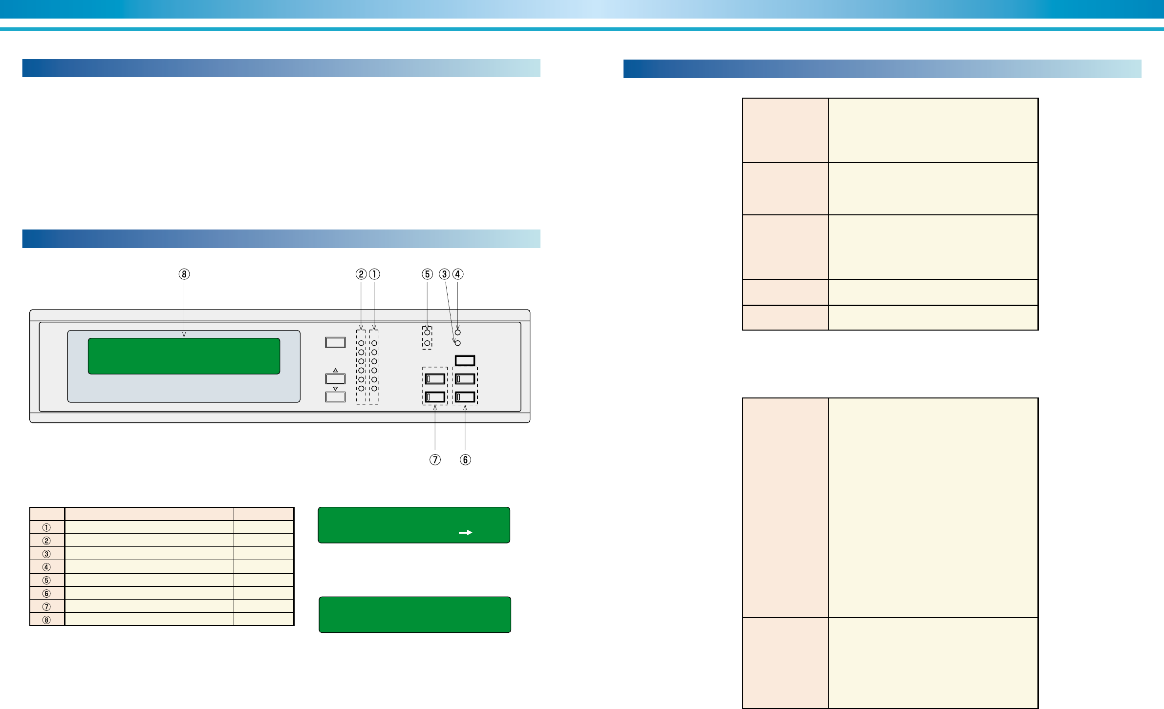
SANYO control system
Display and control board
■ Display(normal)
Table 1. Indication lamp Sample 1.
Sample 2.
Exhaust gas temp 236°C
CH W temp 12.3 7.1°C
Notice : Low level vacuum
Caution : Foul tube of COW
Name Lamp color
Running(Operation) indication lamp Red
Stop indication lamp Green
Alarm indication lamp Orange
Bunner combustion indication lamp Red
Cooling / Heating indication lamp Orange
Remote / Local select button with lamp Red
Mode select button with lamp Red
Data display LCD
symbol
Table 2. Typical operation data
High temperature generator
Exhaust gas
Chilled water
Cooling water
Hot water
Chiller / heater
Combustion
No.1 Absorbent pump
Refrigerant pump
Low level vacuum (Notice / Caution)
High concentration (Notice / Caution)
Foul tube of cooling water (Notice / Caution)
High cooling water temperature (Notice / Caution)
Foul chamber (Notice / Caution) (only for oil-fired types)
Chilled water
Hot water
Chiller / heater
Burner
Temperature
Operation hours
Message
Set point
ON-OFF
Table 3. Typical alarm data
Operation alarm
Others
Generator solution level
Thermal relay of No.1 Absorbent pump
Thermal relay of No.2 Absorbent pump
Thermal relay of burner blower
Thermal relay of oil pump
Thermal relay of refrigerant pump
Interlock of chilled water pump
Interlock of hot water pump
Interlock of cooling water pump
Interlock of system
Generator pressure
Chilled water flow rate
Hot water flow rate
Generator temperature
High concentration
Purge tank pressure sensor
Solution temp sensor
Condensed refrigerant temp sensor
Generator temp sensor
Chilled water sensor
Hot water sensor
Cooling water sensor
Refrigerant temp sensor
Power failure
The SANYO control system surpasses other proportional only control
systems available today. The digital PID(proportional, integral, and dif-
ferential) control maximizes unit performance by maintaining a ±0.5°C
deviation in leaving chilled water temperature from setpoint. Proportional
controls typically can only maintain a ±1°C deviation from setpoint. The
controller's innovative design also incorporates the ability to start and
stop the system chilled/hot and cooling water pumps. During shutdown
these pumps are sequenced to insure a complete dilution cycle.
The leaving chilled water temperature is measured every five seconds
and fuel input is changed according to the gradient of the leaving chilled
water temperature curve. System temperatures, setpoints, and opera-
tional records are displayed along with indicator lights for the chiller, pumps
and burner.
The SANYO control system offers its users self-diagnostics by constantly
monitoring the chiller's status and will automatically shut the chiller down
should a fault occur. The cause of shutdown will be retained in memory
and can be displayed for immediate operator review. The controller's
memory will also retain and display the cause of the last three system
fault conditions. This method of retaining fault conditions is extremely
useful for maintaining an accurate record of unit performance and fault
history.
MODE
SETTING
STOP RUN
CHILLER
BUZZER STOP
STOP LOCAL
REMOTE
OPERATION
ALARM
BURNER
HEATING
COOLING
REF PUMP
#1 ABS PUMP
#2 ABS PUMP
PURGE PUMP
BURNER BLOWER
H Generator temp 149.9°C
Display and control board
89
ENVIRONMENTALLY FRIENDLY TECHNOLOGY SUPER ABSORPTION
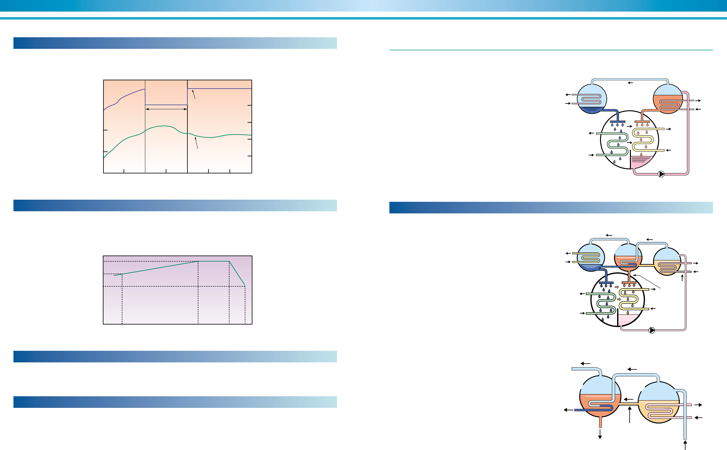
Optimum dilution cycle period can be shortened substantially according to microprocessor monitoring
This results in the appropriate dilution cycle operating hours.
Graph 6. Dilution cycle (DE)
Purge system
The high performance purge system maintains the required operating
pressure, preserves the chiller performance characteristics, minimizes
chiller maintenance as one purge time operation per season in case there
are four(4) seasons.
05
78
10 15 20
20
40
60
80
100
120
140
25 30 35 40
0
7°C
10
20
30
40
Temperature (°C)
Setting
Variable(5-30minutes)15minutes
ex.
Steam consumption
Cooling water inlet temperature
Chilled water inlet temperature
Chilled water outlet temperature
Steam control valve
opening ratio
Steam Consumption ratio (%)
Steam control opening ratio (%)
30minutes
Time(minutes)
Steam valve opening control
Operation
signal
ON
OFF
Chiller /
heater
ON
OFF
Cooling water
pump
ON
OFF
Chilled / hot
water pump
ON
OFF
1 min T 1 1 min T 2
Stop signal Chiller stop
T1: Count the time until generator temperature goes down to 120°C
(About 4 to 20 minutes)
T2: Decide the time by generator temperature.
(About 5 to 10 minutes)
Note :
1) Dilution time in cooling operation is minimum 6 minutes
to maximum 15 minutes.
2) Dilution time in heating operation is 5 minutes.
Unit proper and hot water pump stop in 5 minutes after stop signal is lit.
3) Stop the air conditioning system after complete stop of chiller.
Graph 7. Start up chart (NE)
Open angle of steam control valve at starting is controlled
by means of the three steps, resulting that the excessive
amount of steam and also the consumed time to reach the
desired level became less than the previous model.
Of course, by means of adjusting the open speed of steam
control valve at the second step and the third, it is possible
to set up to the most suitable condition met to the site aux-
iliary equipment.
ON
OFF
16
12
8
4
00 5 10 15 20 25 30 35 40
Time(minutes)
Continuous operation of E model absorbent pump
Load factor 80% Load factor 40%
Conventional
Conventional
Load change
Chilled water inlet temperature
Chilled water outlet temperature
E model
E model
Absorbent
pump
Conventional pump
ON-OFF(3 times)
Temperature
(°C)
Temperature
setting 7°C
100
80
60
40
20
020 40 60 80 100
Cooling load factor(%)
Non-inverter
control
E model
Fuel consumption ratio(%)
Load factor(%)
100
50
30
Temperature(°C)
32
27
25
1. Chilled water outlet temperature 7°C constant
2. Cooling water inlet temperature
Speedy digital PID control
The introduction of new digital PID control to the E-model stabilizes the
chilled/hot water temperature with high accuracy than the previous C
model. It quickly responds to the load fluctuation and supplies stable
Control of high temperature generator by solution level control
With the new control system, solution flow rate is precisely controlled so
that the solution level of the high temperature generator is maintained at
a certain level.
Frequency of maneuvering has been substantially reduced with the syner-
Saving energy with the inverter
Balancing the load and flow rate with the absorbent pump’s inverter con-
trol enables efficient and energy saving operation. As a result, it saves
the
input energy and electric power consumption, running cost by 5%
compared to none-inverter control.
chilled/hot water temperature. It is suitable for air-conditioning intelligent
buildings which require sophisticated control.
getic
effect of absorbent pump inverter control. This enables the supply
of a more
stable temperature for chilled/hot water compared to conven-
tional
models.
Graph 4. Operating result by speedy PID control (gas-fired)
Graph 5. Running cost curve Table 4. Test condition
10 11
ENVIRONMENTALLY FRIENDLY TECHNOLOGY SUPER ABSORPTION
160
150
140
0
0
20
40
60
80
100
5101520253035
Time(minutes)
Steam consumption
control for 10 minutes
Steam consumption ratio
Steam consumption ratio(%)
Temperature of high temp. generator(°C)
Temperature of
high temperature generator
100
80
60
40
20
0★--13 ★+2★★--4
(Variable from 20°C to 33°C)
Maximum input(%)
Cooling water inlet temperature(°C)
High temperature generator safety control
When the temperature of the high temperature generator is higher
than a
certain temperature level, the steam consumption is controlled to
sustain safe
operation.
Expansion of safety operating zone
This ensures quick response to rapid changes and maintains stable
operation.
Safety operating zone is between 19°C and 34°C of cooling water
temperature. (In case cooling inlet water temperature is 32°C)
Crystallization protection
Microprocessor observes the absorbent concentration. Steam supply is
stopped and the unit is recovered to the normal operation when the con-
centration is over certain limit, to prevent the crystallization of absorbent.
Space saving by compact design
With the high performance heat transfer tubes, weight and size is re-
duced by 10% of the previous C model.
The absorption cycle
The absorption cooling cycle, like the compression refrigeration cycle, uti-
lizes the latent heat of evaporation of a refrigerant to remove heat from the
entering chilled water. The compression refrigeration system uses a chlorine
based refrigerant and a compressor to transport the refrigerant vapor to be
condensed in the condenser. The absorption system, however, uses water
as the refrigerant and an absorbent to absorb the vaporized refrigerant. Heat
is then applied to the solution to release the refrigerant vapor from the absor-
bent. The refrigerant vapor is then condensed in the condenser.
The basic absorption cycle (see Figure 1) involves generator, condenser,
evaporator and absorber with refrigerant (liquid) and lithium bromide as the
working solutions. The generator utilizes a heat source (burner, steam or hot
water) to vaporize the diluted lithium bromide solution. The water vapor that
is released travels to the condenser where it is condensed back into a liquid,
transferring the heat to the cooling tower water. Once condensed, the liquid
refrigerant is distributed over the evaporator tubes, removing the heat from
the chilled water and vaporizing the liquid refrigerant. The concentrated lithium
bromide solution from the generator passes into the absorber, absorbs the
refrigerant vapor solution from the evaporator and dilutes itself. The diluted
lithium bromide solution is then pumped back to the generator where the
cycle is started again.
Condenser
Liquid
refrigerant
Cooling
water Concentrated
solution
Chilled water Cooling water
Evaporator
Absorbent pump
Heat source
Generator
Absorber
Refrigerant vapor
Figure 1. Simplified absorption cycle
The generator section is divided into a high temperature generator and a low
temperature generator. The refrigerant vapor produced by the high tempera-
ture generator is used to heat the LiBr solution in the low temperature gen-
erator in which the pressure (hence the boiling point) is lower. Thus the heat
of condensation is effectively utilized.
As mentioned in the single effect type, the refrigerant vapor produced by the
low temperature generator is sent to the condenser to become liquid refriger-
ant. On the other hand, the refrigerant vapor produced by the high tempera-
ture generator turns to water as it releases heat to the intermediate LiBr
solution. This happens inside the heat transfer tubes in the low temperature
generator. The refrigerant vapor produced by both low and high temperature
generators turns to refrigerant liquid and mixes in the condenser before re-
turning to the evaporator.
Figure 2. Double effect absorption cycle
Cooling
water
Heat source
Liquid
refrigerant
Chilled water
Condenser
Refrigerant vapor Refrigerant vapor
Hight temperature
generator
Evaporator
Absorbent pump
Absorber
Diluted solution
Cooling water
Concentrated
solution
Intermediate
solution
Low temperature
generator
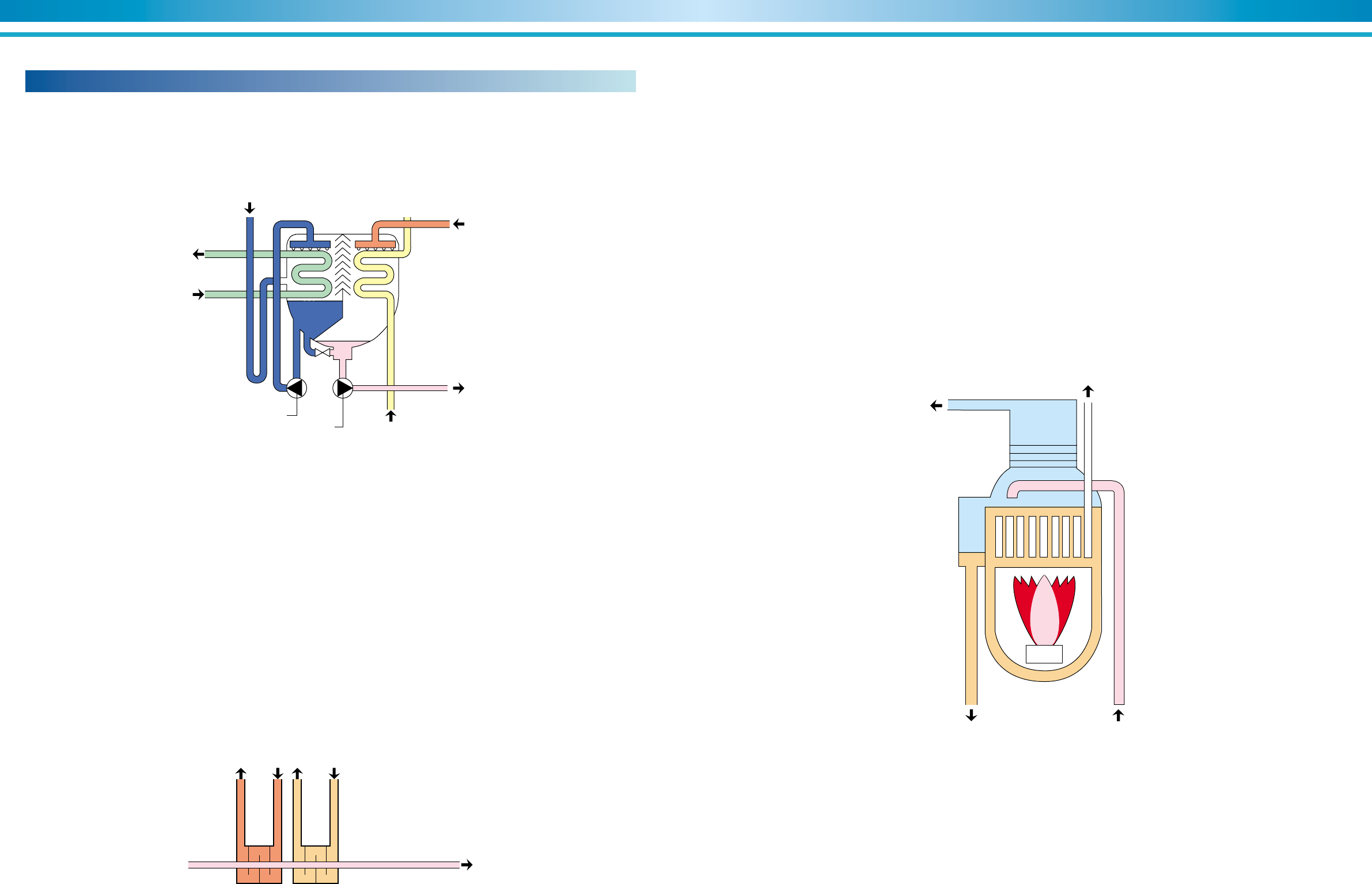
Figure 3. Detail of generator
Refrigerant vapor to condenser
Refrigerant vapor
Heat source
Diluted solution
Concentrated solution
Condensed
refrigerant Intermediate solution
Low temperature generator High temperature generator
Graph 8. Safety control chart
Graph 9. Safety operating chart
Double effect type
Together with the cooling water safety control and absorbent crystallization
pro-
tection control, the safety operating zone is broadened.
12 13
ENVIRONMENTALLY FRIENDLY TECHNOLOGY SUPER ABSORPTION
Absorption cooling cycle
The SANYO super absorption machine applies the same basic absorption
principles but enhances the cycle by adding additional heat exchangers and
a second generator to recover all the available energy of the system and
maximize the unit's COP (see Figure 2).
D. High temperature generator section
The diluted solution from the heat exchangers is heated by the burner or
steam upon entering the high temperature generator and separates into re-
frigerant vapor and intermediate solution (see Figure 6).
Line D' to E of Graph 10 shows the heating and concentration process in the
high temperature generator. The diluted solution at point D' is heated at a
Figure 6. High temperature generator
Burner
High temperature generator
Refrigerant vapor
Exhaust gas
Diluted solutionIntermediate solution
A. Evaporator section
Liquid refrigerant entering the evaporator is dispersed uniformly on the chilled
water evaporator tubes (see Figure 4).
The low pressure of the evaporator causes the refrigerant to be boiled, thus
Chilled water outlet
Chilled water inlet
Absorber
Refrigerant pump
Absorbent pump Cooling water inlet
Liquid refrigerant
Concentrated solution
Diluted solution
Evaporator
Figure 4. Lower shell
The absorption cycle operates in a vacuum. This permits the liquid refriger-
ant to boil at a lower temperature, transferring the latent heat of evaporation
from the entering chilled water to cooling the chilled water.
Below is a component description of the absorption cycle with reference to
the D¨uhring diagram shown in Graph 10 at page 16.
B. Absorber section
Concentrated solution entering the absorber is dispersed uniformly on the
cooling water tubes (see Figure 4). The concentrated solution in the absorber
section absorbs the refrigerant vapor from the evaporator section of the ves-
sel.
Cooling water flowing through the absorber section heat transfer tubes ex-
tracts the heat generated by this absorption process. The concentrated solu-
tion, after absorbing the refrigerant vapor from the evaporator, becomes a
diluted solution.
Concentrated
solution Intermediate
solution
Low temperature
heat exchanger High temperature
heat exchanger
Diluted solution
Figure 5. Heat exchangers
C. Low and high temperature heat exchangers
The diluted solution, after leaving the absorber section, passes through the
low temperature heat exchanger (see Figure 5) where it is heated by the
concentrated solution. The diluted solution then passes through the high tem-
perature heat exchanger where it is further heated by intermediate solution.
The intermediate and concentrated solutions are cooled by the diluted solu-
vaporizing the refrigerant and causing the latent heat of the vaporized refrig-
erant to cool the chilled water.
Line A to B of Graph 10 describes the process in the absorber. The concen-
tration of the lithium bromide solution entering the absorber section is 63.5%
(all concentration levels and temperatures are approximate). The lithium bro-
mide solution then absorbs the refrigerant vapor from the evaporator section
and is cooled from 50°C to 37°C by the cooling water. This causes the bro-
mide solution to become diluted and it then leaves the absorber at a concen-
tration of 57.7% (point B, Graph 10).
tion. This cooling process of the concentrated solution allows for greater ab-
sorbing power due to its lower temperature.
Line B to C to D' of Graph 10 shows the temperature rise of the diluted
solution in the low and high temperature heat exchangers.
E. Low temperature generator section
The refrigerant vapor from the high temperature generator passes through
the heat transfer tubes of the low temperature generator (see Figure 7). The
intermediate solution from the high temperature heat exchanger passes to
the low temperature generator where it is heated by the refrigerant vapor.
The heated intermediate solution releases additional refrigerant vapor and
becomes concentrated to its final level. The condensed refrigerant in the
heat transfer tubes and the refrigerant vapor of the low temperature genera-
tor section then flows to the condenser.
Line F' to F to G of Graph 10 shows the concentrating process in the low
constant concentration to point D, where the refrigerant vapor is released
and the solution becomes concentrated to 60.8% (point E, Graph 10).
Following the intermediate solution, Line E to F' of Graph 10 shows heat
transfer from the intermediate solution to the diluted solution in the high tem-
perature heat exchanger (see Figure 5).
temperature generator. The intermediate solution enters the low tempera-
ture generator and is heated by the refrigerant vapor from the high tempera-
ture generator. Additional refrigerant vapor is released and the intermediate
solution becomes concentrated into its final concentration level of 63.7%
(point G, Graph 10).
Following the concentrated solution, Line G to A' of Graph 10 shows the
process of temperature reduction in the low temperature heat exchanger by
heat transfer to the diluted solution (Figure 5). Line A' to A shows the tem-
perature reduction of the concentrated solution entering the absorber.
14 15
ENVIRONMENTALLY FRIENDLY TECHNOLOGY SUPER ABSORPTION
F. Condenser section
The refrigerant vapor from the low temperature generator is condensed on
the cooling water heat transfer tubes of the condenser (see Figure 7). The
cooling water from the absorber flows through the condenser and removes
the heat of condensation from the refrigerant vapor from the low temperature
Figure 7. Upper shell
Low temperature generator
Refrigerant vapor
Intermediate solution
Concentrated solution
Cooling waterLiquid refrigerant
Condenser
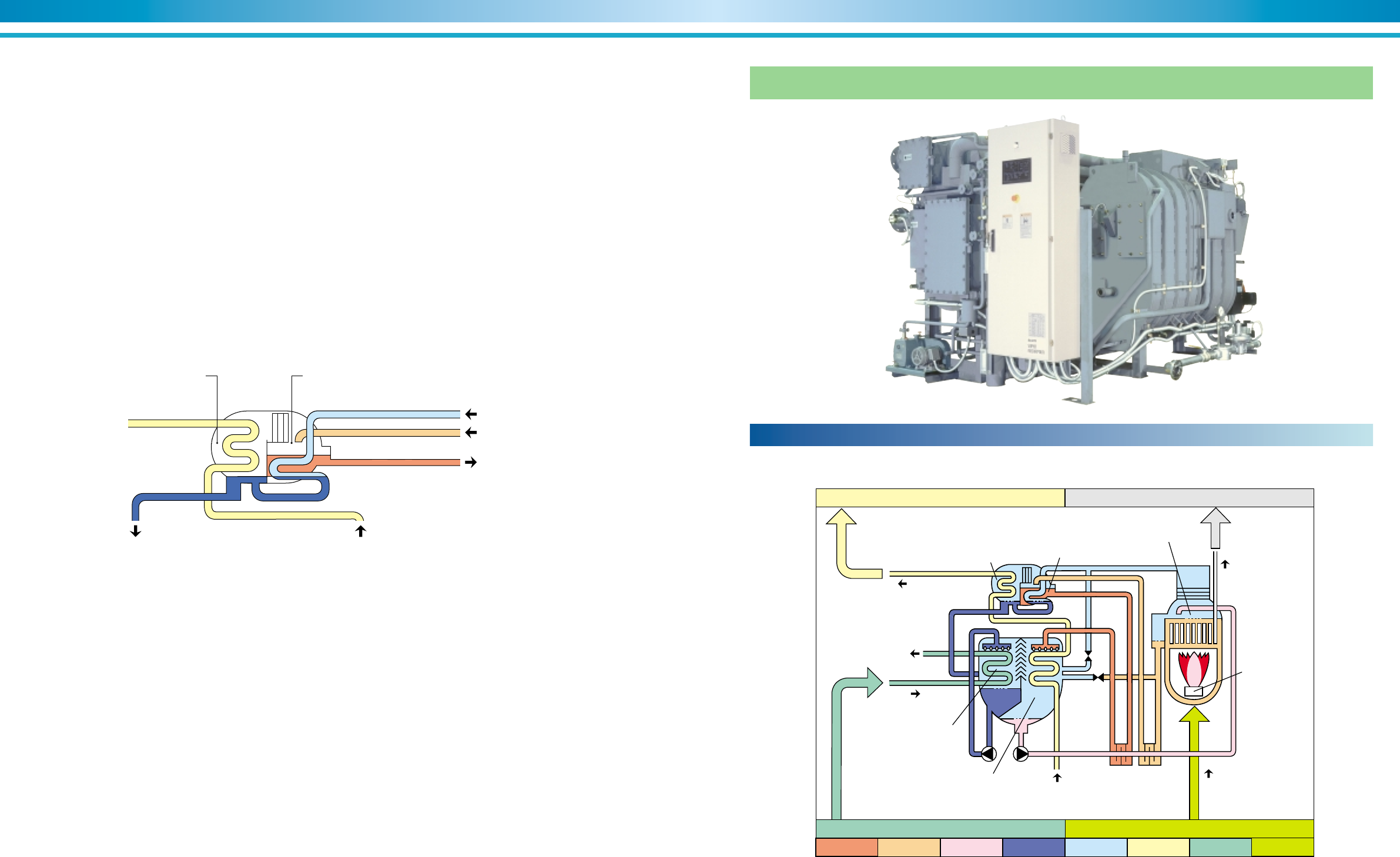
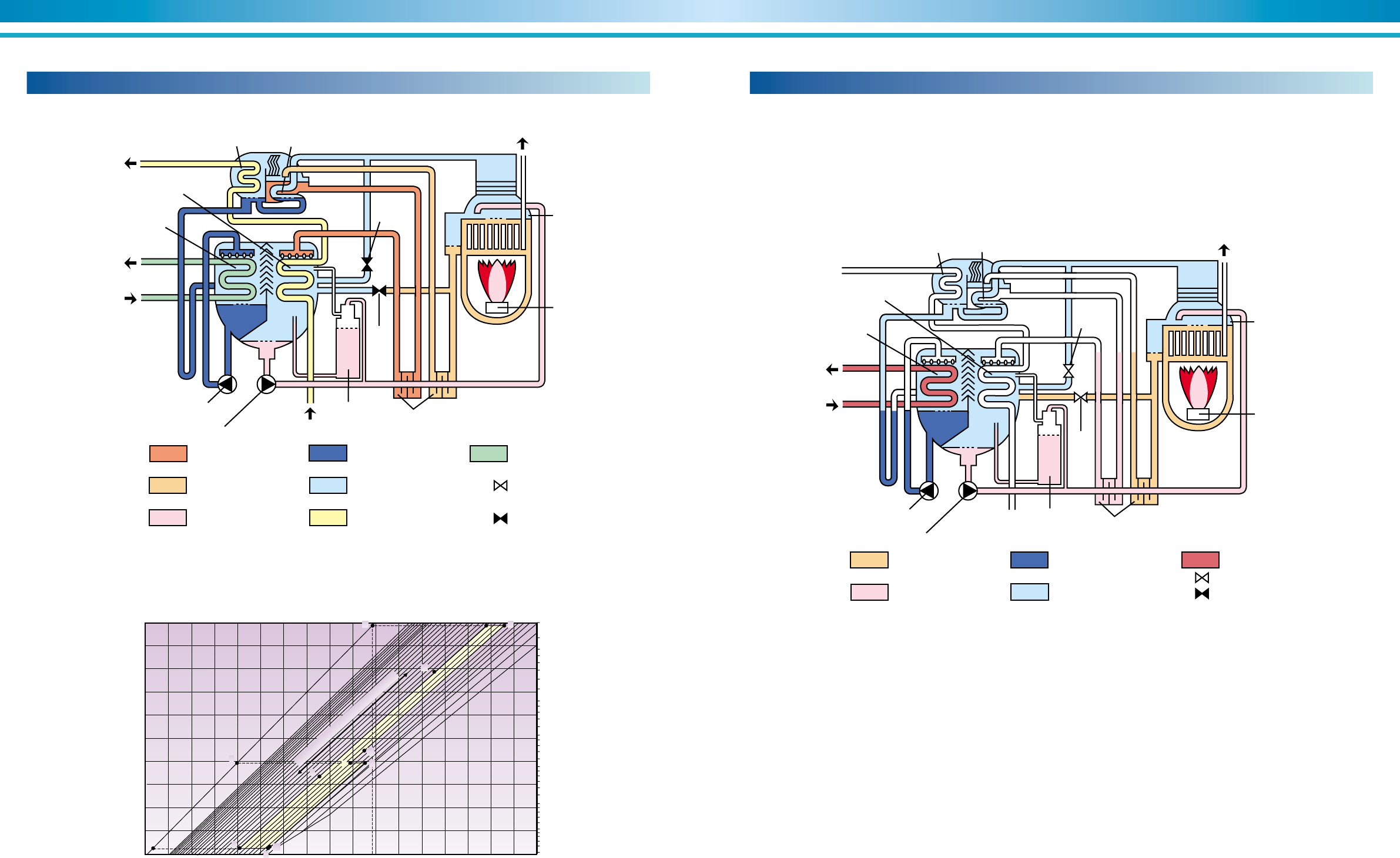
Schematic cooling cycle
Figure 8. Direct-fired chiller / heaters
Exhaust Gas
High Temperature Generator
Burner
Heat Exchanger
Cooling Water
Chilled Water
Evaporator
Absorber
Cooling Water
Condenser
Low Temperature Generator
Fuel
Heat sink 1.8 Waste heat 0.2
Refrigeration capacity 1.0 Heat 1.0
Cooling water Chilled water Heat
Vap. refrigerant
Dil. solutionInt. solutionConc. solution Liq. refrigerant
Direct-fired chiller / heaters
G. Refrigerant path and flow
In the high temperature generator, the heat source separates the refrigerant
from the lithium bromide solution.
The lithium bromide solution follows line D to E of Graph 10.
Line D to H of Graph 10 follows the refrigerant path and illustrates the change
of refrigerant vapor to liquid as it passes through the low temperature gen-
erator. The refrigerant then flows to the condenser (line H to I) where addi-
tional heat is removed. In the low temperature generator additional refriger-
ant is released from the lithium bromide solution (line F to G); this released
refrigerant travels to the condenser (line F to I) where it is condensed into a
generator section and is rejected to the cooling tower.
The condensed (liquid) refrigerant then flows to the evaporator where the
cycle starts again.
liquid. Point I represents the combination of liquid refrigerant from both the
low temperature generator and the condenser. The liquid refrigerant flows
into the evaporator where it mixes with evaporator refrigerant and is pumped
to the evaporator's dispersion trays (line I to J). The refrigerant is dispersed
on the evaporator heat transfer tubes and vaporizes; the vapor is absorbed
by the concentrated solution in the absorber causing the bromide solution to
become diluted (line J to B). The diluted solution flows to the low temperature
heat exchanger (line B to C) where the cycle is repeated.
16 17
ENVIRONMENTALLY FRIENDLY TECHNOLOGY SUPER ABSORPTION
Heating cycle
In the absorption heating cycle (Figure 10), the unit is essentially acting as a
boiler. Diluted solution is heated in the high temperature generator releasing
refrigerant vapor from the absorbent.
The refrigerant vapor flows to the absorber/evaporator and condenses on
the heat transfer tubes of the evaporator. The water through the evaporator
Graph 10. D¨uhring diagram
Condenser
Cooling Water outlet
High Temperature
Generator
Absorber
Cooling Water
A Valve
Chilled Water
Refrigerant Pump
Absorbent Pump Cooling Water Inlet
Purge Unit Heat Exchanger
Evaporator
Burner
Low Temperature Generator Exhaust Gas
Chilled Water
Open
Close
Concentrated Solution
Intermediate Solution
Diluted Solution
Liquid Refrigerant
Refrigerant Vapor
C
Valve
heat transfer tubes removes the sensible heat of the condensed refrigerant
and transfers the heat to the hot water loop. The condensed refrigerant is
mixed with the intermediate solution creating diluted solution. The diluted
solution is pumped back to the high temperature generator where the cycle
is started again.
Figure 10. Heating cycle
Condenser
High Temperature
Generator
Absorber
A Valve
Hot Water
Refrigerant Pump
Absorbent Pump
Purge Unit
Evaporator
Burner
Low Temperature Generator Exhaust Gas
Open
Close
Intermediate Solution
Diluted Solution
Liquid Refrigerant Hot Water
Refrigerant Vapor
C
Valve
Heat Exchanger
100 760
700
500
400
300
200
160
100
80
80
40
30
20
10
8
5
90
80
70
60
Temperature of refrigerant (°C)
Pressure (Torr)
Temperature of absorbent (°C)
50
40
30
20
10
0010 20 30 40
0%
40%
45%
50%
55%
60%
65%
68%
50
J
60 70 80 90 100 110 120 130 140 150 160 170
BA'
A
I
H
C
D'
DE
F'
G
F
Line of Constant Concentrations
Cooling cycle
Figure 9. Cooling cycle
18 19
ENVIRONMENTALLY FRIENDLY TECHNOLOGY SUPER ABSORPTION
Double effect direct-fired absorption chiller / heaters
This is a high efficient-double effect absorption chiller / heaters using combustion heat of gas or oil as the driving
heat source.
It is able to take chilled water of 7°C while hot water of 55°C is in heating mode.
Flow rate
Pressure drop
Connection (JIS)
Holding water volume
Flow rate
Pressure drop
Connection (JIS)
Holding water volume
Flow rate
Pressure drop
Connection (JIS)
Holding water volume
Kind of fuel
Overall dimenstions
Weights
Shipping method
Supply pressure
Cooling consumption
Heating consumption
Fuel connection (JIS)
Flue connection
Length (L)
Width (W)
Height (H)
Tube removal
Electric power
Electric data
Operating weight
Max. shipping weight
Total shipping
weight
No.1 ABS pump
No.2 ABS pump
REF pump
Purge pump
Burner motor
PD cell heater
Control circuit
Total electric current
Apparent power
DE-11 DE-12 DE-13 DE-14 DE-21 DE-22 DE-23 DE-24 DE-31 DE-32
◆ DE Model Specification
100 120 150 180 210 240 280 320 360 400
352 422 527 633 738 844 985 1,125 1,266 1,407
253.0 303.6 379.5 455.4 531.3 607.2 708.4 809.6 910.8 1,012
294 353 441 530 618 706 824 941 1,059 1,177
12 → 7℃(Fouling factor=0.088m
2
℃/kW(0.0001m
2
h℃/kcal)・Max.working pressure 784kPa(8 kgf/cm
2
G))
32 → 37.5℃(Fouling factor=0.088m
2
℃/kW(0.0001m
2
h℃/kcal)・Max.working pressure 784kPa(8 kgf/cm
2
G))
50.8 → 55.0℃(Fouling factor=0.088m
2
℃/kW(0.0001m
2
h℃/kcal)・Max.working pressure 784kPa(8 kgf/cm
2
G))
Natural gas
1 section
3 phase 380V 50Hz
300
0.4
1.1
3,000
1-1/2
29.4
60.5 72.6 90.7 109 127 145 169 194 218 242
4 5 6
4 5 6
5 6 8
0.12 0.13 0.15 0.17 0.22 0.24 0.28 0.30 0.34 0.36
60.5 72.6 90.7 109 127 145 169 194 218 242
6.5 6.6 8.0 8.3 7.5 7.9 5.1 5.5 5.8 6.1
64 65 78 81 74 77 50 54 57 60
300 360 450 540 630 719 840 960 1,080 1,199
349 419 523 628 733 836 977 1,116 1,256 1,394
349 419 523 628 733 836 977 1,116 1,256 1,394
300 360 450 540 630 719 840 960 1,080 1,199
6.5 6.6 8.0 8.3 7.5 7.9 5.1 5.5 5.8 6.1
64 65 78 81 74 77 50 54 57 60
0.31 0.34 0.38 0.42 0.53 0.58 0.63 0.69 0.89 0.95
38 43 64 75 55 61 107 119 85 92
4,900 5,200 6,300 6,800 8,000 8,500 9,800 10,400 12,800 13,500
4,500 4,800 5,800 6,200 7,300 7,700 8,900 9,400 11,600 12,200
4,500 4,800 5,800 6,200 7,300 7,700 8,900 9,400 11,600 12,200
9.3 12.2 13.6 13.7 16.5 18.7
7.2 9.6 10.8 13.1 14.9
1.3 2.5 3.4
3.9 6.8 9.1
0.2 0.4
0.76 1.4 2.6
2.1 3.5 5.7
38 76
1.3 1.8
2,960 3,080 3,700 3,950 4,860 4,950 4,930
1,810 1,980 2,070 2,090 2,280
1,960 2,160 2,390
2,400 3,400 4,500
280×210 310×310 360×310
0.12 0.13 0.15 0.17 0.22 0.24 0.28 0.30 0.34 0.36
3.9 4.4 6.5 7.7 5.6 6.2 10.9 12.1 8.7 9.4
100 120 150 180 210 240 280 320 360 400
(USRT)
kW
(Mcal/h)
kW
m
3
/h
(mH
2
O)
kPa
inch
m
3
m
3
/h
(mH
2
O)
kPa
inch
m
3
m
3
/h
(mH
2
O)
kPa
inch
liter
(mmH
2
O)
kPa
(Mcal/h)
kW
(Mcal/h)
kW
inch
mm
mm
mm
mm
mm
kgf
kgf
kgf
A
kVA
kW
A
kW
A
kW
A
kW
A
kW
A
W
W
Refrigeration
capacity
Heating capacity
Unit
Hot water system
Cooling water system
Chilled water system
Model(TSA-DE-**)
***
***
DE-41 DE-42 DE-51 DE-52 DE-53 DE-61 DE-62 DE-63 DE-71 DE-72 DE-73 DE-81 DE-82
450 500 560 630 700 800 900 1,000 1,100 1,200 1,300 1,400 1,500
1,582 1,758 1,969 2,215 2,461 2,813 3,165 3,516 3,868 4,220 4,571 4,923 5,274
1,138.5 1,265 1,416.8 1,593.9 1,771 2,024 2,277 2,530 2,783 3,036 3,289 3,542 3,795
1,324 1,471 1,647 1,853 2,059 2,353 2,648 2,942 3,236 3,530 3,824 4,119 4,413
272 302 339 381 423 484 544 605 665 726 786 847 907
5.2 5.5 4.6 6.2 8.1 5.7 7.6 9.9 6.2 7.8 9.6 7.8 9.5
0.46 0.48 0.65 0.71 0.77 0.99 1.06 1.13 1.41 1.51 1.61 1.83 1.94
272 302 339 381 423 484 544 605 665 726 786 847 907
5.2 5.5 4.6 6.2 8.1 5.7 7.6 9.9 6.2 7.8 9.6 7.8 9.5
0.46 0.48 0.65 0.71 0.77 0.99 1.06 1.13 1.41 1.51 1.61 1.83 1.94
51 54 45 61 79 56 74 97 61 76 94 76 93
450 500 560 630 700 800 900 1,000 1,100 1,200 1,300 1,400 1,500
10.3 11.2 7.1 9.4 12.1 8.5 11.2 14.4 9.4 11.8 14.5 12.2 14.7
1.11 1.19 1.87 2.01 2.14 2.79 2.97 3.15 3.67 3.90 4.11 4.51 4.76
1,350 1,496 1,683 1,892 2,101 2,398 2,695 3,003 3,300 3,597 3,905 4,202 4,499
1,570 1,740 1,957 2,200 2,443 2,788 3,134 3,492 3,837 4,183 4,541 4,886 5,231
1,570 1,740 1,957 2,200 2,443 2,788 3,134 3,492 3,837 4,183 4,541 4,886 5,231
1-1/2 2 2-1/2 3
410×310 350×500 400×620 400×900
1 section 2 sections
1,350 1,496 1,683 1,892 2,101 2,398 2,695 3,003 3,300 3,597 3,905 4,202 4,499
15,800 16,600 22,200 24,000 25,700 31,900 34,400 37,100 45,100 48,500 51,500 56,100 59,100
14,200 14,900 19,500 21,100 22,700 15,500 16,500 17,700 21,500 23,000 24,300 26,000 27,500
18.7 30.9 36.4 41.7 45.7 54.4 58.9 64.9
3.4 3.7 5.5 7.5
9.1 13.4 15.0 19.0 24.0
1.8 3.0 3.7
0.4 0.75
1.1 1.9
2.6 4.0 6.5 9.0 12.0
5.7 8.0 13.5 18.0 24.0
76 152
5.4 9.1 12.0
14.9 24.9 29.4 33.8 37.1 44.2 47.9 52.9
14,200 14,900 19,500 21,100 22,700 28,100 30,400 32,800 40,000 43,000 45,800 49,700 52,300
4,940 5,260 5,810 6,300 6,040 6,480 7,010 6,430 6,960 7,460 6,960 7,460
4,500 4,600 5,200 5,700 5,200 5,700 6,200 5,700 6,200 6,700 6,200 6,700
2,490 2,990 3,240 4,100 4,450
2,600 2,900 3,330 3,450 3,650
101 110 70 92 119 83 110 141 92 116 142 120 144
8 10 12 14
8 10 12 14
51 54 45 61 79 56 74 97 61 76 94 76 93
12 → 7℃(Fouling factor=0.088m
2
℃/kW(0.0001m
2
h℃/kcal)・Max.working pressure 784kPa(8 kgf/cm
2
G))
32 → 37.5℃(Fouling factor=0.088m
2
℃/kW(0.0001m
2
h℃/kcal)・Max.working pressure 784kPa(8 kgf/cm
2
G))
50.8 → 55.0℃(Fouling factor=0.088m
2
℃/kW(0.0001m
2
h℃/kcal)・Max.working pressure 784kPa(8 kgf/cm
2
G))
Natural gas
3,000
3 phase 380V 50Hz
300
0.4
1.8
29.4
10 12 14 16
***
***
Specifications subject to change without notic
e.
20 21
ENVIRONMENTALLY FRIENDLY TECHNOLOGY SUPER ABSORPTION
1.Absorption chiller / heaters
(1) Lower shell
•Evaporator and refrigerant dispersion tray
•Absorber and absorbent dispersion tray
•Eliminators
(2) Heat exchangers
•High temperature (H.T.) heat exchanger
•Low temperature (L.T.) heat exchanger
(3) Upper shell
•Low temperature (L.T.) generator
•Condenser
•Eliminators
(4) High temperature (H.T.) generator
(5) Burner and gas train
•Dual fuel burner as option
(6) Pumps
•Absorbent pump (s) with isolating valves
•Refrigerant pump with isolating valves
•Purge pump
(7) Control panel
•CE marking (if requested according to the regulation).
(8) Locally mounted controls and instruments
•Temperature sensor
•H.T. generator solution level electrodes
•H.T. generator pressure gauge
(9) Purge device
•Purge tank
•Ejector and liquid trap
•Piping and various manual valves
•Palladium cell with heater
(10) Interconnecting piping and wiring
(11) Initial charge
•Absorbent (lithium bromide)
•Refrigerant
•Inhibitor
(12) Painting
•Main unit: Rust preventive painted
•Control panel: Finish painted
(13) Accessories
•Operation manual : One set
•Washer (for fixing foundation bolts) : One set
•Manometer : One piece
•Gasket and sealant for rupture disk : One set
(if requested according to the regulation).
Scope of supply (DE)
2.Factory test
Tests below are carried out in the SANYO factory.
•Check of external dimensions
•Leak test (vacuum side and gas train)
•Hydraulic test of water headers
•Electric insulation resistance test
•Dielectric breakdown test
•Function test of electric circuit and safety devices
•Performance test only for one section shipping unit.
*One unit is tested when several units of the same model are
ordered for one project.
3.Scope of supply of the purchaser
(1) Unloading, transportation, and insurance depend on the
individual sales contractor between your company and
SANYO groups.
(2) Foundations with foundation bolts.
(3) External chilled/hot water, cooling water, fuel gas and flue
piping work including various safety valves, isolating valves,
etc.
(4) Rupture disk, flange of rupture disk, bolts, nuts, piping work
and tank, etc, if necessary.
(5) External wiring and piping for the chillers including
necessary parts.
(6) Insulation for the chillers including necessary parts.
(7) Mating flanges, gaskets, bolts and nuts
•Gas inlet nozzle flange of gas train.
•Exhaust gas outlet nozzle flange.
•Inlet / outlet nozzle flanges of chilled/hot water. (evaporator)
•Inlet / outlet nozzle flanges of cooling water.
(absorber / condenser)
(8) Finish painting of the chillers.
(9) Cooling water inlet temperature control device.
(10) Various temp. / press. gauges for gas and water lines.
(11)
Cooling tower (s), chilled water pump (s), hot water pump (s)
and cooling water pump (s) and its auxiliary accessaries.
(12) Electric power supply (specified value).
(13) Supply of chilled water, cooling water, hot water and gas at
rated conditions.
(14) Necessary tools, workers and materials for installation and
site test operation.
(15)
After-sales service and periodical maintenance of the chillers.
(16) Any other item not specifically mentioned in the scope of
supply.
Scope of order (DE)
Item
Chilled water
Hot water
Max. working pressure
Hydraulic test pressure
Fouling factor
Material of tube
Water quality
Structure of water header
Manufacturing standard of water header
Temperature
Flow rate
Max. working pressure
Hydraulic test pressure
Fouling factor
Material of tube
Water quality
Structure of water header
Manufacturing standard of water header
Kind of gas
Supply gas pressure
Phase
Voltage
Frequency
Shipment
Safety functions
Capacity control
Parts
Painting
Indication lamps
Display
External terminals
(no-voltage normal open contact)
Structure
Parts
Electrical wiring and piping
Place
Ambient temperature
Ambient humidity
Atmosphere
Option
Outlet : 5°C~12°C
Temperature difference: 3°C~10°C
Changes depending on chilled water temperature
difference (min. flow rate : 50%)
Max. outlet temperature: 60°C
Additional heater : Max 80°C
Flow rate should correspond to chilled water flow rate
DE-11~42 : Max. 2 rank up
DE-51~81 : Max. 1 rank up
981∼1961kPa (10kg/cm2G~20kg/cm2G)
Max. working press.✕1.5 times (0.196m2°C/kW)
Max. 0.176m2°C/kW (0.0002m2h°C/kcal)
No option
No option
No option
No option
Inlet : 20.0°C~33.0°C
Within the water flow range of each model
981∼1961kPa (10kg/cm2G~20kg/cm2G)
Max. working press.✕1.5 times
Max. 0.196m2°C/kW (0.0002m2h°C/kcal)
No option
No option
No option
No option
LPG, Kerosine, Diesel oil
Contact SANYO's representative
Contact SANYO's representative
Multi-shipment
Cooling water flow switch
No option
No option
No option
No option
No option
No option
No option
No option
No option
No option
No option
No option
No option
No option
Standard
Inlet : 12.0°C
Outlet : 7.0°C
0.605m3/h•RT
Inlet : 50.8°C
Outlet : 55.0°C
0.605m3/h•RT
784kPa (8kg/cm2G)
Max. working press.+196kPa (2kg/cm2)
0.088m2°C/kW (0.0001m2h°C/kcal)
Copper tube
Refer to JRA-GL02E-1994
Removal type
SANYO standard
Inlet : 32.0°C
Outlet : 37.5°C
1.0m3/h•RT
784kPa (8kg/cm2G)
Max. working press.+196kPa (2kg/cm2)
0.088m2°C/kW (0.0001m2h°C/kcal)
Copper tube
Refer to JRA-GL02E-1994
Removal type
SANYO standard
Natural gas
29.4kPa(3,000mmH2O)
3 phase 380V 50Hz
(Voltage regulation : within ± 10%)
(Frequency regulation : within ± 5%)
One-section : DE-11 thru DE-53
Two-sections : DE-61 thru DE-82
Refrigerant temperature supervision
Chilled water freeze protection
Chilled water flow switch
Hot water temperature supervision
Cooling water temperature supervision
H.T. generator temperature supervision
H.T. generator press. supervision
H.T. generator level. supervision
Exhaust gas temperature supervision
Crystallization protection
Motor protection
Digital PID control by chilled water outlet temperature
Inverter control of No.1 absorbent pump
Selected by SANYO
Munsell 5Y-7/1
Operation : red
Stop : green
Equipment alarm : orange
LCD
Indoor type
Selected by SANYO
Wire : 600V grade polyvinyl chloride-insulated wires
Pipe : plicatube (flexible metal conduits)
Indoor
5°C~40°C
Relative humidity : Max.90% (45°C)
Be sure the following are not present:
•Corrosive gas
•Explosive gas
•Poisonous gas
Installation condition
Control panel Control Electricity Fuel Cooling water Chilled/hot water
Temperature
Flow rate
Temperature
Flow rate
Rank up
Operation indication
Stop indication
Alarm indication
Ventilation fan operation
Answer back indication
Combustion indication
Cooling mode indication
Heating mode indication
22 23
ENVIRONMENTALLY FRIENDLY TECHNOLOGY SUPER ABSORPTION
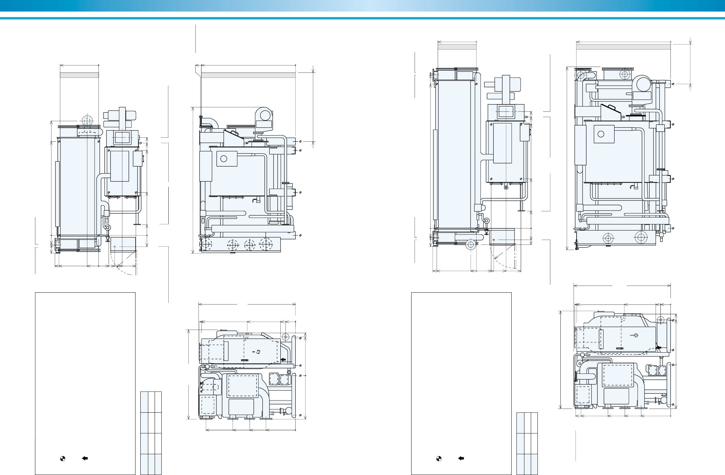
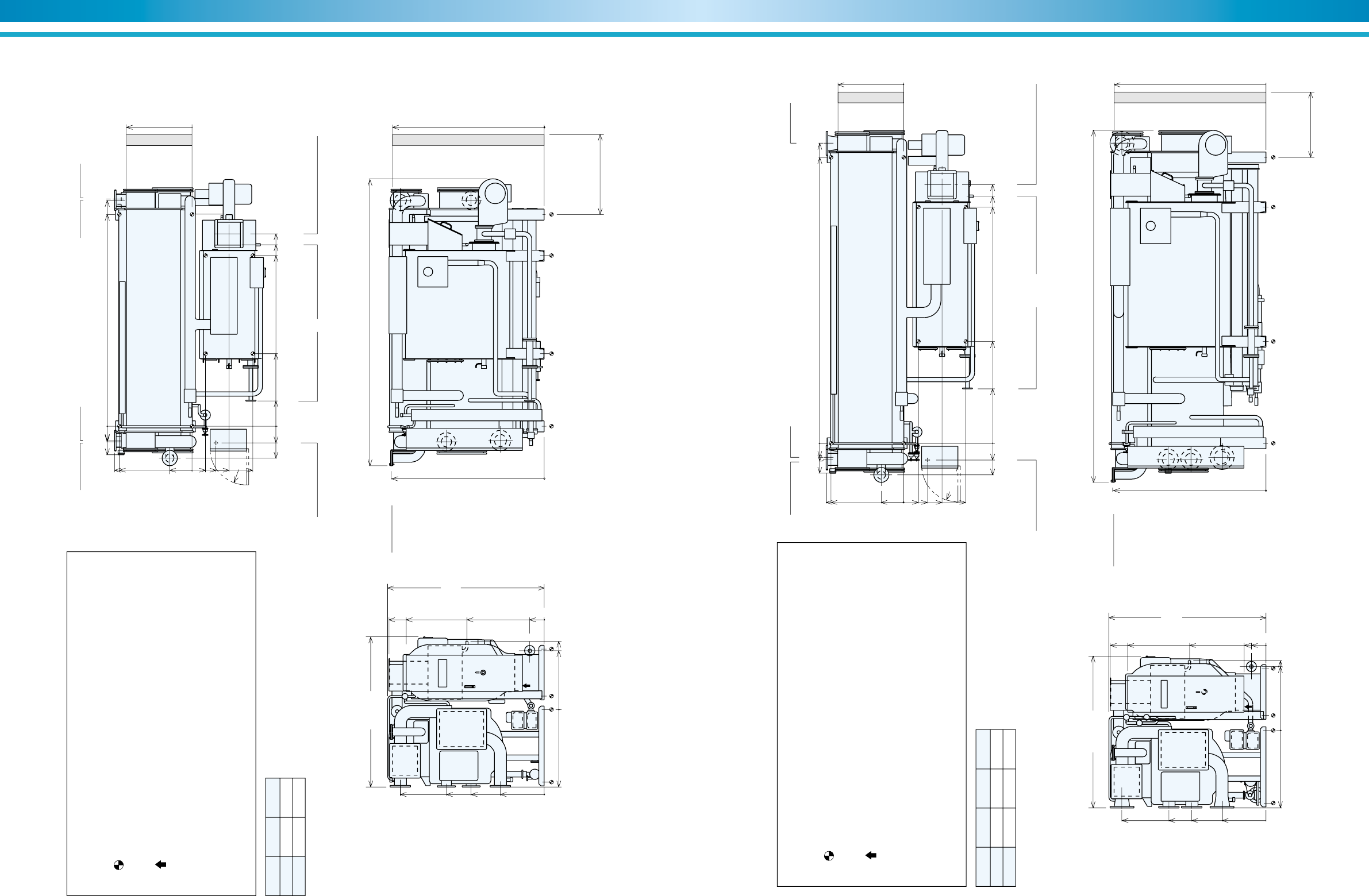
Model A B L
DE-11 215 865 2960
DE-12 15 665 3080
Figure 11. DE-11 Thru DE-12
NOTES
1. Dimensions (L), (W), (H) are for the unit with rupture disk.
The dimensions are changed if additional parts are added.
2. indicates the position of anchor bolts.
3. All external water piping with welded JIS 10K flanges are to be provided by
the customer.
4. indicates the position of the power supply connection on control panel.
(diameter 33 mm)
5. Service space:
Longitudinal distance –1000 mm
Top –200 mm
Others –500 mm
6. Regarding fuel connection diameter and position, refer to specifications.
1810(W) L
2400
(Tube removal space either side)
1960
(H)
1940
1900
1921
777
0
Rupture Disk
4 inch
1904
0
975
300
200
0
882
0
780
863
882
800
229
0
205
325
755
480 R500
1809
1265
923
595
0
COW outlet
5 inch
COW inlet
5 inch
CHW outlet
4 inch
CHW out / in COW in / out
CHW inlet
4 inch
230
0
1715
1865
1975
365
200
180
1896
2311
AB
Flue connection 280✕210
Fuel connection
1-1/2 inch
Wire connection ø33 hole Chamber drain PT1
0
Model A B
DE-13 350 1000
DE-14 150 800
Figure 12. DE-13 Thru DE-14
NOTES
1. Dimensions (L), (W), (H) are for the unit with rupture disk.
The dimensions are changed if additional parts are added.
2. indicates the position of anchor bolts.
3. All external water piping with welded JIS 10K flanges are to be provided by
the customer.
4. indicates the position of the power supply connection on control panel.
(diameter 33 mm)
5. Service space:
Longitudinal distance –1000 mm
Top –200 mm
Others –500 mm
6. Regarding fuel connection diameter and position, refer to specifications.
1980(W) 3700(L)
3400
(Tube removal space either side)
1960
(H)
1940
1900 1904
0
934
300
200
0
882
0
910
1030
1921
882
800
112
0
300
350
600
900
R500
1809
1265
923
595
0
Rupture Disk
4 inch
COW outlet
5 inch
COW inlet
5 inch
CHW outlet
4 inch
CHW out COW in COW out CHW in
CHW inlet
4 inch
328
230
0
2100
2251
2361
365
200
180
0
2916
3096
3116
AB
Flue connection 280✕210
Fuel connection
1-1/2 inch
Wire connection
ø33 hole Chamber drain PT1
24 25
ENVIRONMENTALLY FRIENDLY TECHNOLOGY SUPER ABSORPTION
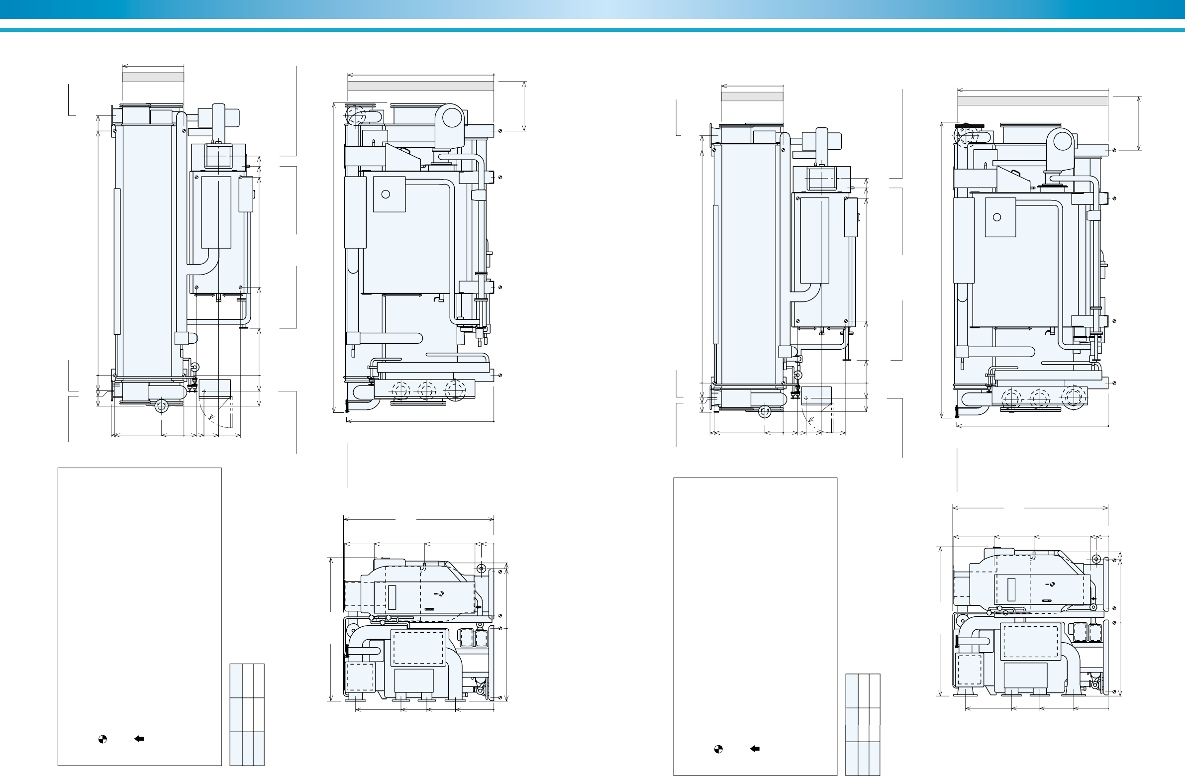
Model A B
DE-21 350 1000
DE-22 150 800
Figure 13. DE-21 Thru DE-22
NOTES
1. Dimensions (L), (W), (H) are for the unit with rupture disk.
The dimensions are changed if additional parts are added.
2. indicates the position of anchor bolts.
3. All external water piping with welded JIS 10K flanges are to be provided by
the customer.
4. indicates the position of the power supply connection on control panel.
(diameter 33 mm)
5. Service space:
Longitudinal distance –1000 mm
Top –200 mm
Others –500 mm
6. Regarding fuel connection diameter and position, refer to specifications.
2070(W) 3950(L)
3400
(Tube removal space either side)
2160
(H)
2140
1900
2089
905
0
0
1064
200
0
1065
0
810
940
2106
1921
1065
1000
306
0
185
330
510
835
R500
1980
1346
1006
603
0
Rupture Disk
4 inch
COW outlet
6 inch
COW inlet
6 inch
CHW outlet
5 inch
CHW in/out COW in COW out CHW in
CHW inlet
5 inch
438
230
0
2350
2501
2652
390
212
195
0
2916
3111
3128
AB
Flue connection 310✕310
Fuel connection
1-1/2 inch
Wire connection
ø33 hole Chamber drain PT1
Model A B L
DE-23 750 1400 4860
DE-24 550 1200 4950
Figure 14. DE-23 Thru DE-24
NOTES
1. Dimensions (L), (W), (H) are for the unit with rupture disk.
The dimensions are changed if additional parts are added.
2. indicates the position of anchor bolts.
3. All external water piping with welded JIS 10K flanges are to be provided by
the customer.
4. indicates the position of the power supply connection on control panel.
(diameter 33 mm)
5. Service space:
Longitudinal distance –1000 mm
Top –200 mm
Others –500 mm
6. Regarding fuel connection diameter and position, refer to specifications.
2090(W)
L
4500
(Tube removal space either side)
2160
(H)
2140
1900
2088
903
0
0
1050
300
200
0
1065
0
880
960
2106
0
1065
1000
306
0
205
330
530
855
R500
1980
1333
1019
603
0
Rupture Disk
4 inch
COW outlet
8 inch
COW inlet
8 inch
CHW outlet
6 inch
CHW in/out COW in COW out
CHW inlet
6 inch
438
230
0
2350
3400
3561
411
221
195
0
3936
4131
AB
Flue connection 310✕310
Fuel connection
1-1/2 inch
Wire connection
ø33 hole Chamber drain PT1
26 27
ENVIRONMENTALLY FRIENDLY TECHNOLOGY SUPER ABSORPTION
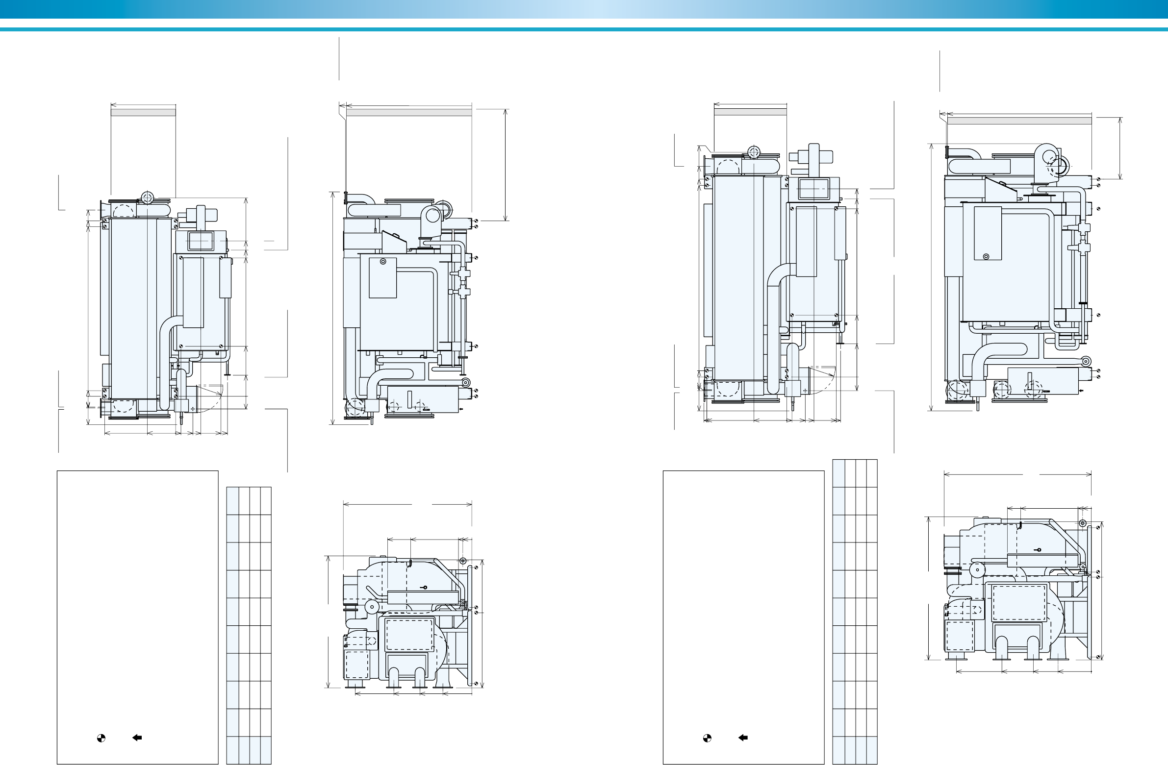
Model A B
DE-31 750 1400
DE-32 550 1200
Figure 15. DE-31 Thru DE-32
NOTES
1. Dimensions (L), (W), (H) are for the unit with rupture disk.
The dimensions are changed if additional parts are added.
2. indicates the position of anchor bolts.
3. All external water piping with welded JIS 10K flanges are to be provided by
the customer.
4. indicates the position of the power supply connection on control panel.
(diameter 33 mm)
5. Service space:
Longitudinal distance –1000 mm
Top –200 mm
Others –500 mm
6. Regarding fuel connection diameter and position, refer to specifications.
2280(W) 4930(L)
4500
(Tube removal space either side)
2390
(H)
2370
1900
2323
978
0
0
1100
200
300
0
1156
0
950
1042
2340
0
1156
1100
358
0
200
320
550
900
R500
2198
1476
1066
611
0
Rupture Disk
4 inch
COW outlet
8 inch
COW inlet
8 inch
CHW outlet
6 inch
CHW in/out COW in COW out
CHW inlet
6 inch
488
255
0
3150
3325
3486
494
250
245
0
3886
4131
AB
Flue connection 360✕310
Fuel connection
1-1/2 inch
Wire connection
ø33 hole Chamber drain PT1
Model A B
DE-41 380 1030
DE-42 180 830
Figure 16. DE-41 Thru DE-42
NOTES
1. Dimensions (L), (W), (H) are for the unit with rupture disk.
The dimensions are changed if additional parts are added.
2. indicates the position of anchor bolts.
3. All external water piping with welded JIS 10K flanges are to be provided by
the customer.
4. indicates the position of the power supply connection on control panel.
(diameter 33 mm)
5. Service space:
Longitudinal distance –1000 mm
Top –200 mm
Others –500 mm
6. Regarding fuel connection diameter and position, refer to specifications.
2490(W) 4940(L)
4500
(Tube removal space either side)
2600
(H)
2580
1900
2513
1032
0
0
1236
200
300
0
1221
0
1065
1184
2531
0
1221
1150
307
0
245
385
645
1045
R500
2383
1613
1142
577
0
Rupture Disk
4 inch
COW outlet
10 inch
COW inlet
10 inch
CHW outlet
8 inch
CHW in/out COW in COW out
CHW inlet
8 inch
478
255
0
3080
3255
3416
492
276
244
0
3886
4130
AB
Flue connection 410✕310
Fuel connection
1-1/2 inch
Wire connection
ø33 hole Chamber drain PT1
28 29
ENVIRONMENTALLY FRIENDLY TECHNOLOGY SUPER ABSORPTION
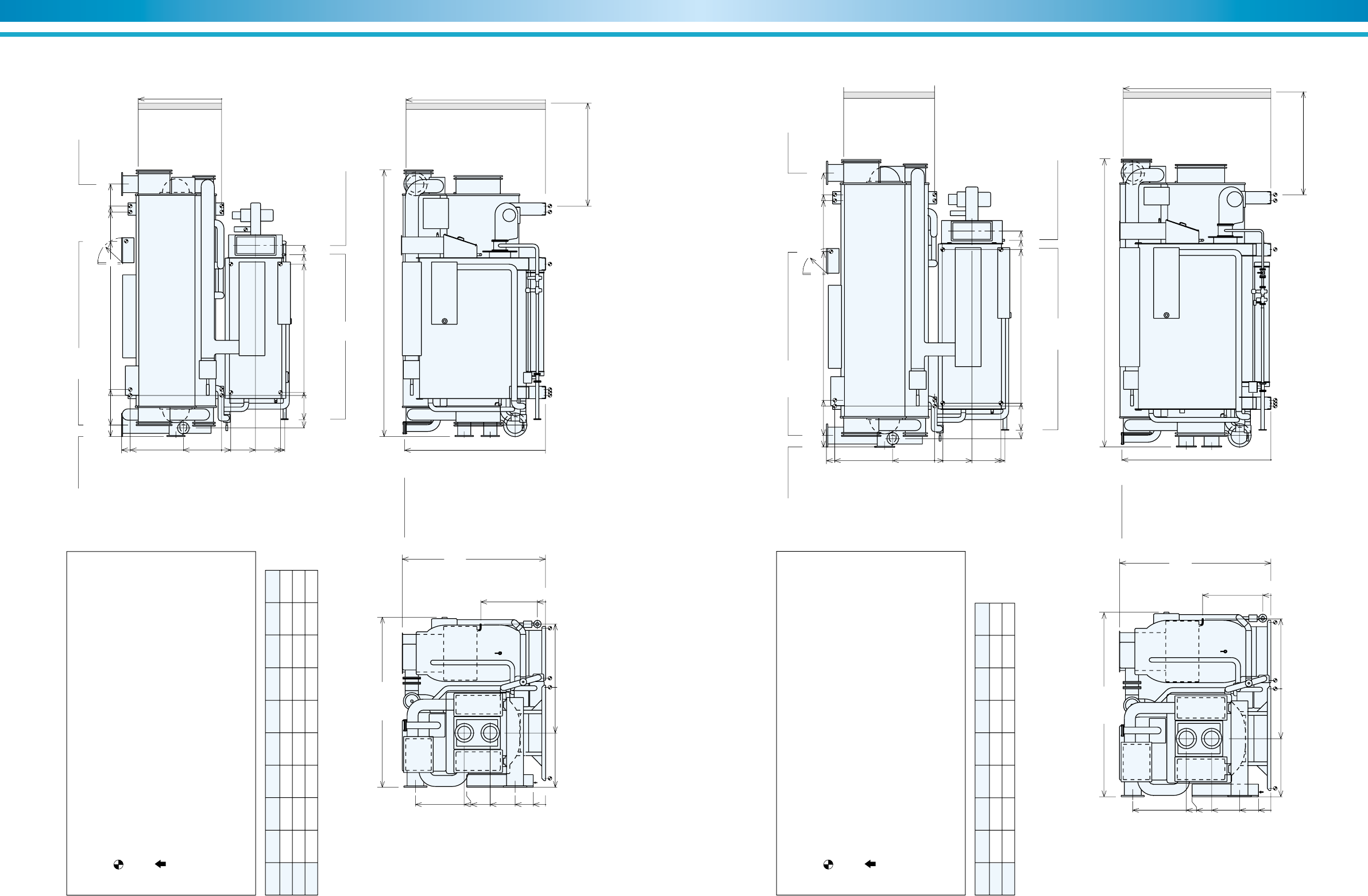
Model A B C D E F G K L
DE-51 3836 3966 4206 3130 3305 3511 4482 4600 5260
DE-52 4378 4508 4748 3330 3505 3711 5024 5200 5810
DE-53 4876 5006 5246 3530 3705 3911 5522 5700 6300
Figure 17. DE-51 Thru DE-53
NOTES
1. Dimensions (L), (W), (H) are for the unit with rupture disk.
The dimensions are changed if additional parts are added.
2. indicates the position of anchor bolts.
3. All external water piping with welded JIS 10K flanges are to be provided by
the customer.
4. indicates the position of the power supply connection on control panel.
(diameter 52 mm)
5. Service space:
Longitudinal distance –1000 mm
Top –200 mm
Others –500 mm
6. Regarding fuel connection diameter and position, refer to specifications.
2990(W)
L
K
(Tube removal space either side)
2900
(H)
1900
1378
2855
2825
1463
0
0
200
300
0
1700
0
1198
1600
634
0
120
390
570
1170
1020
R600
2630
1760
1170
650
0
Rupture Disk
6 inch
COW outlet
12 inch
COW inlet
12 inch
CHW outlet
8 inch
CHW in/out COW out COW in
CHW inlet
8 inch
480
1130
290
0
640
265
240
0
130
DE
AB C
FG
Flue connection 350✕500
Fuel connection
1-1/2 inch
Wire connection
ø54 hole Chamber drain 1-1/2 inch
Model A B C D E F G K L M
DE-61 4328 4468 4758 5076 3798 4023 4252 5200 6040 2
DE-62 4826 4966 5256 5574 4098 4323 4552 5700 6480 2
DE-63 5350 5490 5780 6099 4398 4623 4852 6200 7010 2-1/2
Figure 18. DE-61 Thru DE-63
NOTES
1. Dimensions (L), (W), (H) are for the unit with rupture disk.
The dimensions are changed if additional parts are added.
2. indicates the position of anchor bolts.
3. All external water piping with welded JIS 10K flanges are to be provided by
the customer.
4. indicates the position of the power supply connection on control panel.
(diameter 52 mm)
5. Service space:
Longitudinal distance –1000 mm
Top –200 mm
Others –500 mm
6. Regarding fuel connection diameter and position, refer to specifications.
3240(W) L
K
(Tube removal space either side)
3330
(H)
1900
1634
3286
3260
1635
0
0
200
300
0
1870
1255
0
1870
1800
736
0
120
420
620
1220
1120
R600
3050
2025
1315
753
0
Rupture Disk
6 inch
COW outlet
14 inch
COW inlet
14 inch
CHW outlet
10 inch
CHW in/out
COW out COW in
CHW inlet
10 inch
748
1398
310
0
765
310
292
0
140
E
AB C D
FG
Flue connection 400✕620
Fuel connection
M inch
Wire connection
ø52 hole Chamber drain
1-1/2 inch
30 31
ENVIRONMENTALLY FRIENDLY TECHNOLOGY SUPER ABSORPTION
Model A B C D E F K L M
DE-71 4426 4566 5096 3170 3395 3620 5700 6430 2-1/2
DE-72 4950 5090 5620 3470 3695 3920 6200 6960 3
DE-73 5450 5590 6120 3770 3995 4220 6700 7460 3
Figure 19. DE-71 Thru DE-73
NOTES
1. Dimensions (L), (W), (H) are for the unit with rupture disk.
The dimensions are changed if additional parts are added.
2. indicates the position of anchor bolts.
3. All external water piping with welded JIS 10K flanges are to be provided by
the customer.
4. indicates the position of the power supply connection on control panel.
(diameter 52 mm)
5. Service space:
Longitudinal distance –1000 mm
Top –200 mm
Others –500 mm
6. Regarding fuel connection diameter and position, refer to specifications.
4100(W)
L
K
(Tube removal space either side)
3450
(H)
1564
3360
2005
0
0
200
0
2410
1100
1528
0
2410
2200
920
0
220
820
1520
1420
3135
3395
1335
735
300
0
Rupture Disk
6 inch
COW outlet
16 inch
CHW outlet
12 inch
1960
1900
CHW outlet
12 inch
CHW in/out COW in COW out
COW inlet
16 inch
580
786
0
70
990
710
0
140
3720
ED
AB C
F
Flue connection
400✕900
Fuel connection
M
inch
Wire connection ø52 hole
Wire
connection
ø52 hole
Chamber drain
1-1/2 inch
R600
Model A B C D E F K L
DE-81 4950 5090 5620 3770 3995 4220 6200 6960
DE-82 5450 5590 6120 3970 4195 4420 6700 7460
Figure 20. DE-81 Thru DE-82
NOTES
1. Dimensions (L), (W), (H) are for the unit with rupture disk.
The dimensions are changed if additional parts are added.
2. indicates the position of anchor bolts.
3. All external water piping with welded JIS 10K flanges are to be provided by
the customer.
4. indicates the position of the power supply connection on control panel.
(diameter 52 mm)
5. Service space:
Longitudinal distance –1000 mm
Top –200 mm
Others –500 mm
6. Regarding fuel connection diameter and position, refer to specifications.
4450(W)
K
(Tube removal space either side)
3650
(H)
1647
3560
0
0
2185
200
0
2600
1200
1688
0
2600
2400
1006
0
200
900
1700
1600
3330
3587
1430
757
300
0
Rupture Disk
6 inch
COW outlet
16 inch
CHW outlet
14 inch
2040
1900
CHW outlet
14 inch
CHW in/out COW in COW out
COW inlet
16 inch
580
786
0
70
990
710
0
140
3720
ED
AB C
F
Flue connection
400✕900
Fuel connection
3 inch
Wire connection ø52 hole
Wire
connection
ø52 hole
Chamber drain
1-1/2 inch
R600
L
32 33
ENVIRONMENTALLY FRIENDLY TECHNOLOGY SUPER ABSORPTION
Foundation dimensional data (DE)
NOTES :
1. Shaded area indicates the base of absorption chiller/heaters.
2. A reasonably level concrete foundation must be provided on which
to mount the chiller.
3. Provide a floor drainage ditch around foundation of the chiller.
4. If foundation anchoring is required, supply anchor bolts and nuts. Fix
anchor bolts on the foundation prior to chiller installation and as per
detail of weld (Figure 21). Washers are supplied with the chiller.
Figure 21. Details of weld
5. For direct-fired (DE) chiller/heaters, provide support for the burner
and gas train.
6. Unit must be level before startup. See leveling information in ” Instal
lation and Application Data ” section of this catalog.
Washer
Base
Nut
Weld
A=150mm and more
80
A
Figure 22. DE-11 Thru DE-12
AA
BB
AA
C
CC
E
AB
H
G
F
N
LG
M
K
H
T
S
R
U
G
P
Q
Figure 23. DE-13 Thru DE-63
E
G
AB
Q
S
R
T
L
K
F
N
D
H
G
M
J
D
C
P
AA AA
CC BB
D
G
C
D
KE
L
U
J
A
P
M
R
T
F
G
N
B
H
AA AA
BB
CC
Q
S
J
H
G
Figure 24. DE-71 Thru DE-82
Model
No.
Weight (kg) Dimensions (mm)
4,900 1,600 900 800 865 850 1,896 -- 800 1,100 150 175 350
5,200 1,700 1,000 800 665 1,050 1,896 -- 800 1,100 150 175 350
6,000 2,100 1,200 900 1,000 1,100 2,916 -- 800 1,100 150 175 350
6,800 2,300 1,300 900 800 1,300 2,916 -- 800 1,100 150 175 350
8,000 2,700 1,400 1,200 1,000 1,350 2,916 -- 1,000 1,300 150 175 350
8,500 2,800 1,600 1,300 800 1,550 2,916 -- 1,000 1,300 150 175 350
9,800 3,300 1,700 1,500 1,400 1,850 3,936 -- 1,000 1,300 150 175 350
10,400 3,500 1,900 1,500 1,200 2,050 3,936 -- 1,000 1,300 150 175 350
12,800 4,400 2,200 1,800 1,400 1,750 3,886 -- 1,100 1,400 150 200 400
13,500 4,500 2,400 2,100 1,200 1,950 3,886 -- 1,100 1,400 150 200 400
15,800 5,400 2,700 2,300 1,030 2,050 3,886 -- 1,150 1,450 150 200 400
16,600 5,500 3,000 2,600 830 2,250 3,886 -- 1,150 1,450 150 200 400
22,200 8,000 3,300 2,900 1,130 2,000 3,966 130 1,600 1,960 180 190 510
24,000 8,600 3,600 3,200 1,130 2,200 4,508 130 1,600 1,960 180 190 510
25,700 9,200 3,900 3,400 1,130 2,400 5,006 130 1,600 1,960 180 190 510
31,90011,300 4,900 4,400 1,398 2,400 4,468 140 1,800 2,160 180 310 560
34,40012,100 5,400 4,800 1,398 2,700 4,966 140 1,800 2,160 180 210 560
37,10013,000 5,800 5,300 1,398 3,000 5,490 140 1,800 2,160 180 210 560
45,10015,900 6,900 6,400 70 3,100 4,566 140 2,200 2,560 180 210 560
48,50017,000 7,600 6,900 70 3,400 5,091 140 2,200 2,560 180 210 560
51,50018,000 8,100 7,400 70 3,700 5,594 140 2,200 2,560 180 210 560
56,10019,500 8,900 8,200 70 3,700 5,091 140 2,400 2,760 180 210 560
59,10020,600 9,300 8,600 70 3,900 5,591 140 2,400 2,760 180 210 560
DE-11
DE-12
DE-13
DE-14
DE-21
DE-22
DE-23
DE-24
DE-31
DE-32
DE-41
DE-42
DE-51
DE-52
DE-53
DE-61
DE-62
DE-63
DE-71
DE-72
DE-73
DE-81
DE-82
Oper.
AA BB CC A B C D E F G H I K L M N P Q R S T U
150 550 850 175 350 150 650 150 900 1,855
150 550 850 175 350 150 650 150 900 1,855
150 600 900 175 350 150 700 150 900 --
300 600 900 175 350 150 700 150 900 --
185 650 950 175 350 150 750 150 1,100 --
185 650 950 175 350 150 750 150 1,100 --
205 650 950 175 350 150 750 150 1,100 --
205 650 950 175 350 150 750 150 1,100 --
200 700 1,000 200 400 200 800 200 1,200 --
200 700 1,000 200 400 200 800 200 1,200 --
245 800 1,100 200 400 200 900 200 1,250 --
245 800 1,100 200 400 200 900 200 1,250 --
120 900 1,260 230 460 200 1,000 250 1,700 --
120 900 1,260 230 460 200 1,000 250 1,700 --
120 900 1,260 230 460 200 1,000 250 1,700 --
120 1,000 1,360 280 560 300 1,100 300 1,900 --
120 1,000 1,360 280 560 300 1,100 300 1,900 --
120 1,000 1,360 280 560 300 1,100 300 1,900 --
220 1,200 1,560 280 560 300 1,300 300 2,300 --
220 1,200 1,560 280 560 300 1,300 300 2,300 --
220 1,200 1,560 280 560 300 1,300 300 2,300 --
200 1,400 1,760 280 560 300 1,500 300 2,500 --
200 1,400 1,760 280 560 300 1,500 300 2,500 --
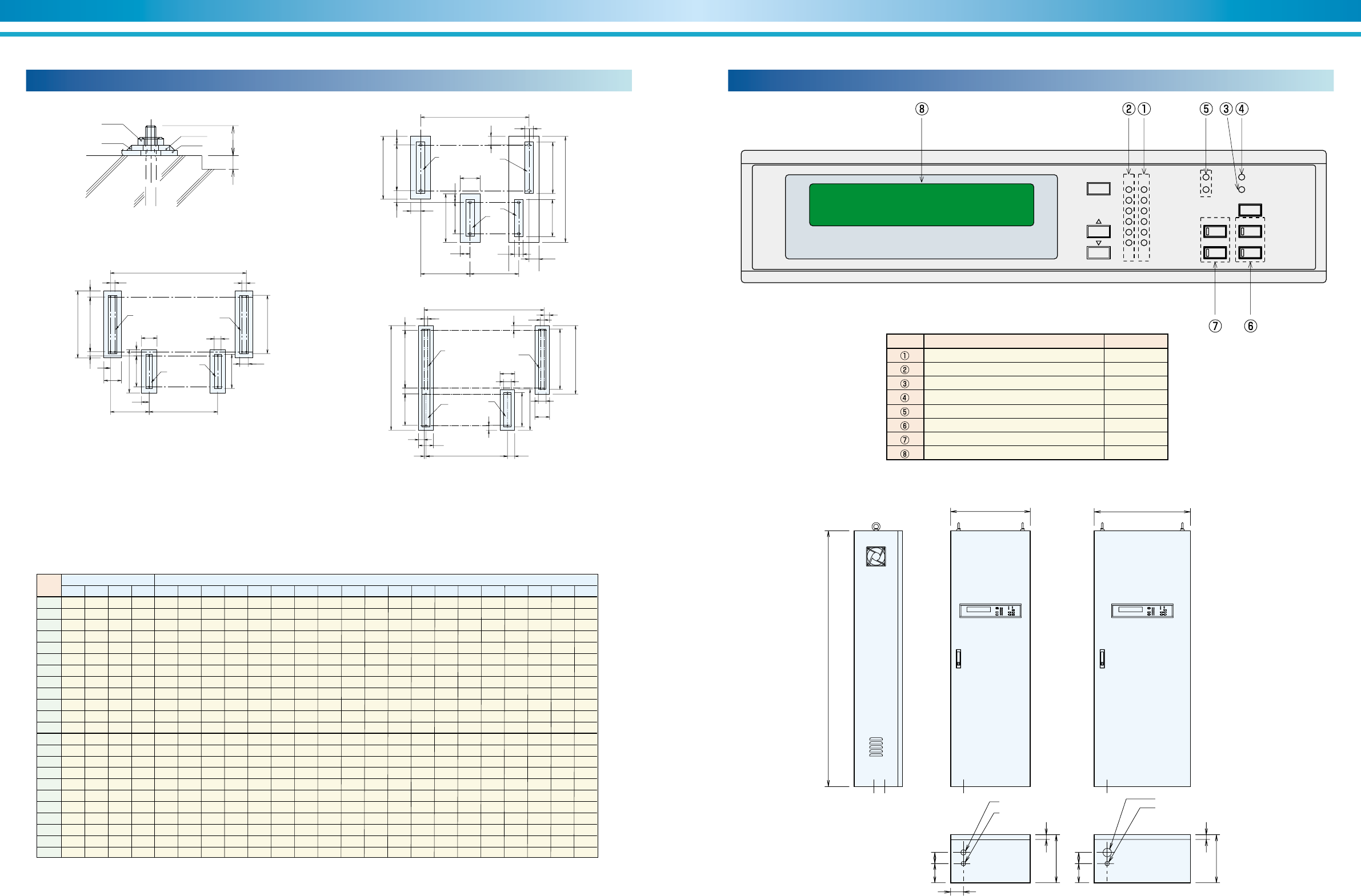
Name Lamp color
Running(Operation) indication lamp Red
Stop indication lamp Green
Alarm indication lamp Orange
Bunner combustion indication lamp Red
Cooling / Heating indication lamp Orange
Remote / Local select button with lamp Red
Mode select button with lamp Red
Data display LCD
symbol
Control panel (DE)
MODE
SETTING
STOP RUN
CHILLER
BUZZER STOP
STOP LOCAL
REMOTE
OPERATION
ALARM
BURNER
HEATING
COOLING
REF PUMP
#1 ABS PUMP
#2 ABS PUMP
PURGE PUMP
BURNER BLOWER
H Generator temp 149.9°C
DE--11 thru DE--42 DE--51 thru DE--82
1600
500
300 30
70
120
80
300 30
70120
600
Power supply ø52
Remote control ø27
Power supply ø33
Remote control ø27
Table 5. Dimensional data
Table 6. Indication lamp
Figure 25. Control panel
34 35
ENVIRONMENTALLY FRIENDLY TECHNOLOGY SUPER ABSORPTION
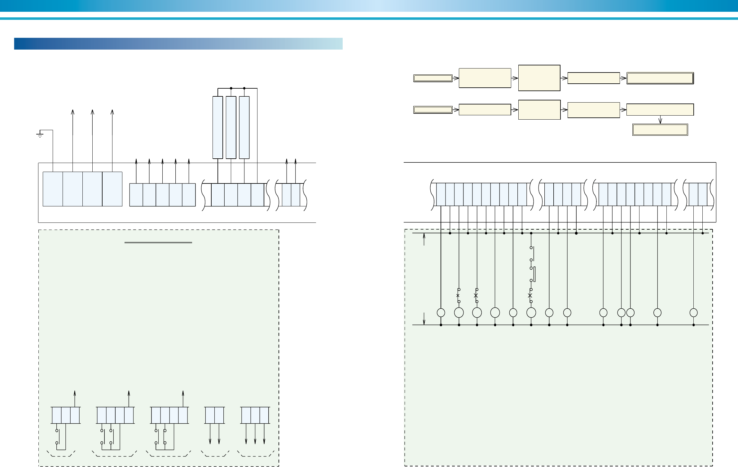
Field wiring (DE)
Figure 26. Typical electrical field connection diagram - Direct-fired (DE)
Chilled/hot water
pump interlock
To power source
3 Ph,50/60Hz
400V, 415V, 440V
171
84
E
R0
S0
T0
85
For message signal
(52CH)
138
Cooling water
pump interlock (52CO)
The unit can be operated by the following five type signal.
(1)Non-voltage normal open contact(A) for start & stop (DC24V 10mA).
:Wiring the terminal 330 and 333.
(2)Non-voltage normal open contact(A) for start (DC24V 10mA).
:Wiring the terminal 330 and 333.
Non-voltage normal open contact(A) for stop (DC24V 10mA).
:Wiring the terminal 331 and 333.
(3)Non-voltage normal open contact(A) for start (DC24V 10mA).
:Wiring the terminal 330 and 333.
Non-voltage normal close contact(B) for stop (DC24V 10mA).
:Wiring the terminal 331 and 333.
(4)Continuous signal of DC/AC 24V for start & stop.
:Wiring the terminal 330 and 332.(Those terminals are non-polarity.)
(5)Pulse signal of DC/AC 24V for start.
:Wiring the terminal 330 and 332.(Those terminals are non-polarity.)
Signal of DC/AC 24V for stop.
:Wiring the terminal 331 and 332.(Those terminals are non-polarity.)
Remote signal
330
A
DC/AC 24VDC/AC 24V
Terminal strips in the control panel
(4)(1) (5)
136
135
Ventilation fan
interlock (52F)
4Y
1
1
2
3
4
10
For emergency stop signal
(Those terminals are
connected by jumper)
Remove the jumper
before using
those terminals
333
332
171 171
330
A
(2)
4Y
1
331
333
332
4Y
2
AB
4Y
2
332
4Y
1
331
333
(3)
A
330
330
332
330
332
331
171
COM
Terminal strips in the control panel
LL
Max. voltage and
Max. current
:AC 250V,0.1A
Stop
indication
Operation
indication
Answer back
indication
52
CT
Chilled/hot
water pump
52
CH
51
CH 51
CT
Cooling tower
fan
52
CO
23
CO
Ventilation
fan
51
CO
52
CO
Cooling water
pump
Note
1.Be sure to insert 23CO at the cooling water inlet side.
2.Be sure to wire the 52CH(interlock) between terminals 171 and 136.
3.Be sure to wire the 52CO(interlock) between terminals 171 and 135.
4.Be sure to wire the 52F(interlock) between terminals 171 and 138.
5.Be sure to wire the chilled/hot water pump control relay between terminals 302 and 303.
6.Be sure to wire the cooling water pump control relay between terminals 304 and 305.
7.Be sure to wire the ventilation fan between terminals 306 and 307.
L
Heating mode
indication
L :Indication lamp
51CH:Chilled/hot water pump overcurrent relay
51CO:Cooling water pump overcurrent relay
51CT :Cooling tower fan overcurrent relay
23CO:Cooling tower fan thermostat
Symbols
Start/Stop sequence of auxiliary equipments
Start
Start signal Machine operates
Chilled/hot water pump
operates and
ventilation fan operates
Stop air conditioners
Cooling water pump
operates and then
cooling tower fan
operates
Stop
Stop signal Diluted operation starts Chiller stops entirely
Cooling water pump
stops and cooling
tower fan stops
Operate air conditioners
52
F
L L
Combustion
indication
Chilled/hot water pump stops
and ventilation fan stops
300
301
302
303
304
305
306
307
308
309
314
315
316
317
320
321
322
323
324
325
326
327
335
334
L
Remote signal
indication
L
Cooling mode
indication
L
Alarm
indication
L
Buzzer signal
indication
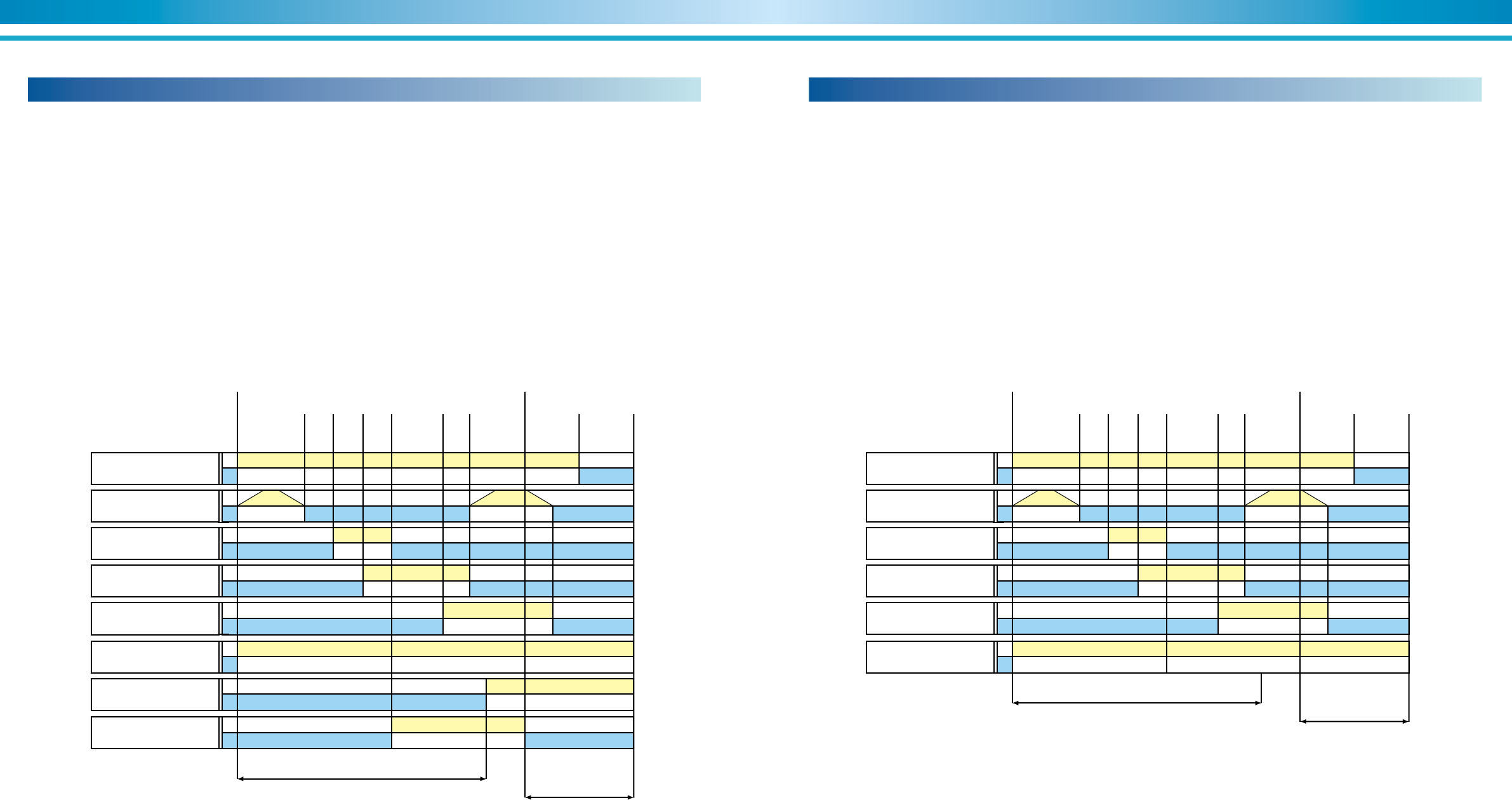
36 37
ENVIRONMENTALLY FRIENDLY TECHNOLOGY SUPER ABSORPTION
Sequence of cooling operation (DE)
Figure 27 illustrates the typical operating sequence of a SANYO DE di-
rect-fired absorption chiller / heaters. The NE steam-fired unit does not
include the time delays associated with the burner blower, gas valve and
ignition functions.
With a chilled water setpoint of 6.7°C and with the chiller/heaters en-
abled, the start signal will be energized as the leaving chilled water tem-
perature rises to 7.7°C, 1.0°C above setpoint.
The burner initially completes a 36-seconds pre-purge operation that in-
cludes gas valve and supply air damper modulation to full open to insure
complete purging of the combustion chamber.
The No. 1 absorbent pump flow rate is changed during all stages of op-
eration to insure quicker start-up and optimum performance at part load.
As the cooling load is satisfied with the chiller/heaters at minimum load,
the unit will cycle off as the leaving chilled water temperature drops to
5.5°C, 1.5°C below setpoint.
When the microprocessor issues a stop signal, the generator heat source
will shut off and the dilution cycle will start. The dilution cycle will last
between 6 and 15 minutes depending on generator temperature. The
dilution cycle will consist of stopping of the refrigerant pump, absorbent
pump(s), and the cooling water pump in turn. The unit is capable of re-
starting during the dilution cycle.
Figure 27. Typical combustion time chart (cooling operation)
Figure 28 illustrates the typical operating sequence of a SANYO DE di-
rect-fired absorption chiller/heaters in heating mode.
With a hot water setpoint of 55°C, the start signal will be energized as the
leaving heating water temperature drops to 54°C, 1.0°C below setpoint.
The burner initially completes a 36-second pre-purge operation that in-
cludes gas valve and supply air damper modulation to full open to insure
complete purging of the combustion chamber. The No. 1 absorbent pump
flow rate is varied during all stages of operation to insure quicker start-up
and optimum performance at part load. On chiller/heaters with two ab-
sorbent pumps, the No. 2 pump remains off at all times during the heat-
ing mode.
As the heating load is satisfied with the chiller/heaters at minimum load,
the unit will cycle off as the leaving heating water temperature rises to
57°C, 2°C above setpoint.
When the microprocessor receives a stop signal, the generator heat
source will shut off and the dilution cycle will begin. The dilution cycle will
last approximately 5 minutes depending on generator temperature. The
dilution cycle consists of timed stopping of the No. 1 absorbent pump.
The chiller/heaters is capable of restarting during the dilution cycle.
Figure 28. Typical combustion time chart (heating operation)
Sequence of heating operation (DE)
Burner
Blower
ON
OFF
Gas control
valve
Open
Close
Sol. valve
Ignition gas
ON
OFF
No. 2 ABSO
pump
ON
OFF
Ignition ON
OFF
Refrigerant
pump
ON
OFF
Dilution cycle
Approx. 6 -- 15 min.
Approx. 5 min.
Pre-purge
36 sec.
Post-purge
12 sec.
Control
area
Chiller stop
Stop signalStart signal
4
sec.
2
sec.
2
sec.
8
sec.
Sol. valve
Main gas
ON
OFF
No. 1 ABSO
pump
ON
OFF
Burner
Blower
ON
OFF
Gas control
valve
Open
Close
Sol. valve
Ignition gas
ON
OFF
Ignition ON
OFF
Dilution cycle
Approx. 5 min.
Approx. 5 min.
Pre-purge
36 sec.
Post-purge
12 sec.
Control
area
Chiller stop
Stop signalStart signal
4
sec.
2
sec.
2
sec.
8
sec.
Sol. valve
Main gas
ON
OFF
No. 1 ABSO
pump
ON
OFF
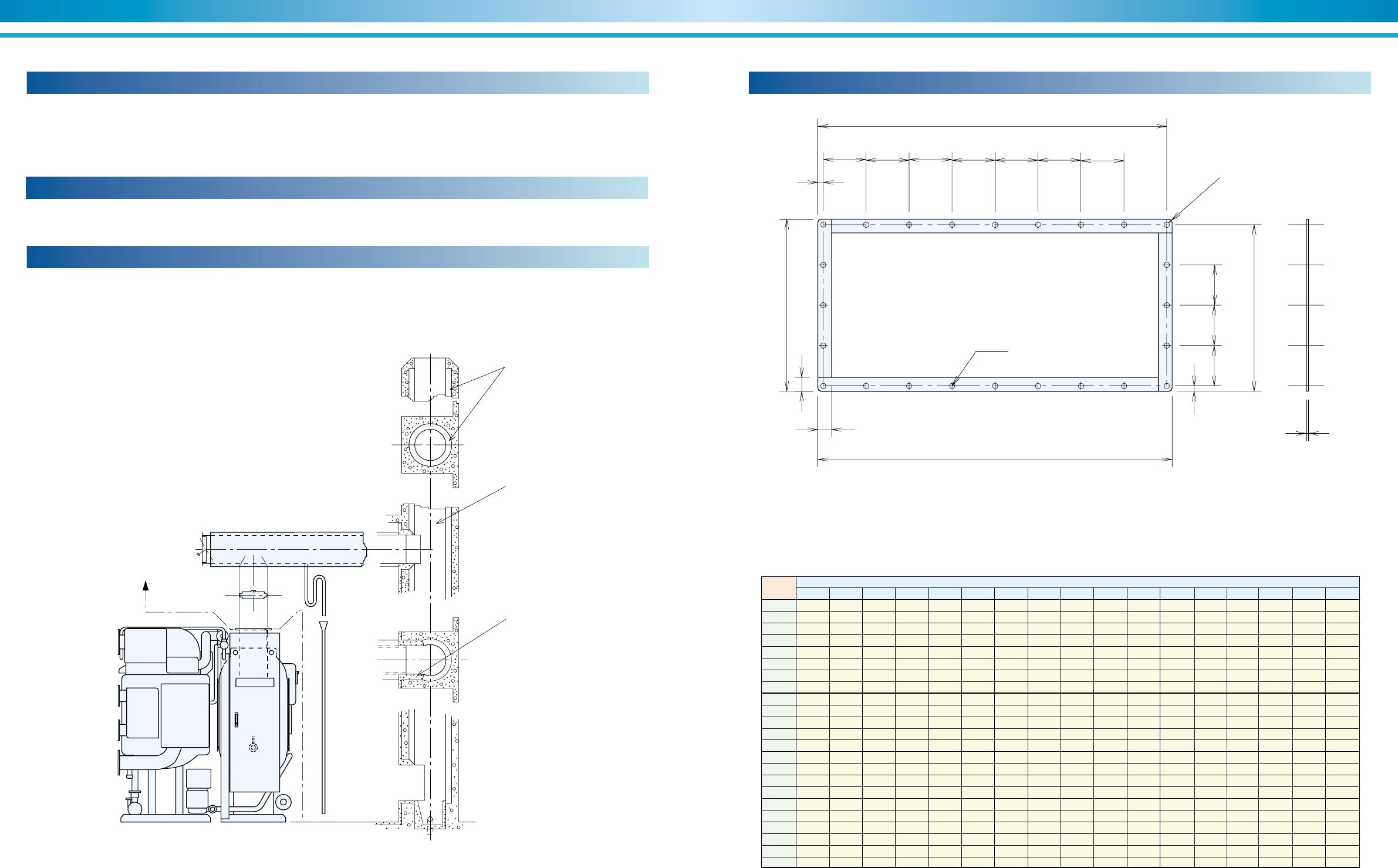
38 39
ENVIRONMENTALLY FRIENDLY TECHNOLOGY SUPER ABSORPTION
The flue and stack must be heat-insulated and provided with a damper
and a condensate drain.
The flue should never be connected to an incinerator stack.
Locate the top end of the smoke stack at a sufficiently large distance
away from the cooling tower.
Figure 29. Typical flue and stack installation
Flue & stack connection
If the same stack is used for discharging exhaust from two systems, the
back flow of exhaust should be prevented from going into the one which
is out of operation.
Provide a draft regulator if fluctuations in static pressure are expected
inside the flue.
As illustrated, the steel stack should be lined on the interior surface as a
protection from corrosion due to exhaust gas.
Typical steel stack
Municipal codes in many areas may regulate large capacity chillers con-
suming oil or gas as fuel.
Such regulations should be strictly abided by.
Compliance with local regulation
NOTES :
Please design the draft pressure at flue flange of the chiller/heaters with
negative pressure 0 thru -29.4Pa (0 thru -3mmH2O).
Field supply
Condensate drain
Condensate drain
Internal lining
Stack
Fire-proof mortar
Flue(Insulated)Draft regulator
Damper
Figure 30. Flue flange
6
A
BCDE F G H
K
N P Q
R
A
S
L
M
M
4-R 10
øT hole
NOTE :
1. Field supply
2. Steel material
Model
No.
Dimensions (mm)
15 110 110 110 --- --- --- ---
15 110 110 110 --- --- --- ---
15 110 110 110 --- --- --- ---
15 110 110 110 --- --- --- ---
15 120 120 --- --- --- --- ---
15 120 120 --- --- --- --- ---
15 120 120 --- --- --- --- ---
15 120 120 --- --- --- --- ---
20 100.5 100.5 100.5 --- --- --- ---
20 100.5 100.5 100.5 --- --- --- ---
15 115 115 115 --- --- --- ---
15 115 115 115 --- --- --- ---
15 139.5 139.5 139.5 --- --- --- ---
15 139.5 139.5 139.5 --- --- --- ---
15 139.5 139.5 139.5 --- --- --- ---
15 113 113 113 113 113 --- ---
15 113 113 113 113 113 --- ---
15 113 113 113 113 113 --- ---
15 119 120 120 120 120 120 120
15 119 120 120 120 120 120 120
15 119 120 120 120 120 120 120
15 119 120 120 120 120 120 120
15 119 120 120 120 120 120 120
DE-11
DE-12
DE-13
DE-14
DE-21
DE-22
DE-23
DE-24
DE-31
DE-32
DE-41
DE-42
DE-51
DE-52
DE-53
DE-61
DE-62
DE-63
DE-71
DE-72
DE-73
DE-81
DE-82
ABCDEFGHKLMNPQRST
345 360 38 130 130 --- 275 290 15
345 360 38 130 130 --- 275 290 15
345 360 38 130 130 --- 275 290 15
345 360 38 130 130 --- 275 290 15
375 390 38 120 120 --- 375 390 15
375 390 38 120 120 --- 375 390 15
375 390 38 120 120 --- 375 390 15
375 390 38 120 120 --- 375 390 15
422 442 38 117 118 --- 372 392 15
422 442 38 117 118 --- 372 392 15
475 490 38 120 120 --- 375 390 15
475 490 38 120 120 --- 375 390 15
573 588 38 137 137 -- 426 441 15
573 588 38 137 137 -- 426 441 15
573 588 38 137 137 -- 426 441 15
693 708 38 114.5 114.5 114.5 473 488 15
693 708 38 114.5 114.5 114.5 473 488 15
693 708 38 114.5 114.5 114.5 473 488 15
973 988 38 113 113 112 464 479 19
973 988 38 113 113 112 464 479 19
973 988 38 113 113 112 464 479 19
973 988 38 113 113 112 464 479 19
973 988 38 113 113 112 464 479 19
Table 7. Dimensional data
Flue flange dimensional data
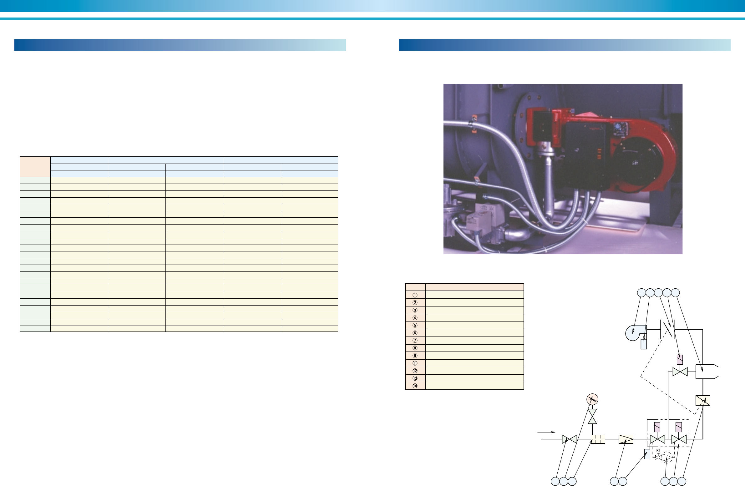
40 41
ENVIRONMENTALLY FRIENDLY TECHNOLOGY SUPER ABSORPTION
The DE direct-fired chiller/heaters are equipped with a nozzle mix burner.
The burners are capable of firing with natural gas.
The burner is factory wired and tested prior to shipment. Manual modula-
tion from low fire to high fire during startup and routine maintenance pro-
cedures is provided by an operation switch in the chiller control panel.
Burner description
The burner maximizes flame retention at all capacity ranges of modula-
tion, thus ensuring long life and efficient operation.
The following drawing illustrates some of the common components found
in a typical gas train and unit installation. Individual jobs may vary de-
pending on chiller size and specific application.
Gas train
Figure 31. Typical burner and gas train
12
11 13 914
54 76
8
GAS
1 2 3
P
Air
P
Parts name.
Ball valve
Pressure gauge with push button valve
Gas filter
Low pressure governor
Gas pressure switch
Double solenoid valve (DMV)
Gas butterfly valve
Valve proving system (VPS)
Solenoid valve for ignition gas
Blower
Air pressure switch1
Air damper
Burner
symbol
Model No.
Gas burner
Natural gas
Model
Kerosene / light oil
Model
Natural gas & kerosene
Model
Natural gas & heavy oil
Model
Heavy oil
Model
Oil burner Dual fuel (combination) gas / oil burner
G1 ZMD --- --- RGL3 ZMD ---
G3 ZMD RL3 ZMD --- RGL3 ZMD ---
G3 ZMD RL3 ZMD --- RGL3 ZMD ---
G3 ZMD RL3 ZMD --- RGL3 ZMD ---
G5 ZMD RL3 ZMD --- RGL5 ZMD ---
G5 ZMD RL5 ZMD --- RGL5 ZMD ---
G5 ZMD RL5 ZMD --- RGL5 ZMD ---
G7 ZMD RL5 ZMD RMS 7 ZMD RGL7 ZMD RGMS7 ZMD
G7 ZMD RL7 ZMD RMS 7 ZMD RGL7 ZMD RGMS7 ZMD
G7 ZMD RL7 ZMD RMS 7 ZMD RGL7 ZMD RGMS7 ZMD
G7 ZMD RL7 ZMD RMS 7 ZMD RGL7 ZMD RGMS7 ZMD
G7 ZMD RL7 ZMD RMS 7 ZMD RGL7 ZMD RGMS7 ZMD
G8 ZMD RL7 ZMD RMS 8 ZMD RGL8 ZMD RGMS8 ZMD
G8 ZMD RL8 ZMD RMS 8 ZMD RGL8 ZMD RGMS8 ZMD
G9 ZMD RL8 ZMD RMS 9 ZMD RGL9 ZMD RGMS9 ZMD
G9 ZMD RL8 ZMD RMS 9 ZMD RGL9 ZMD RGMS9 ZMD
G9 ZMD RL8 / 2 ZMD RMS 9 ZMD RGL9 ZMD RGMS9 ZMD
G9 ZMD RL8 / 2 ZMD RMS 10 ZMD RGL9 ZMD RGMS10 ZMD
G10 ZMD RL9 ZMD RMS 10 ZMD RGL10 ZMD RGMS10 ZMD
G10 ZMD RL10 ZMD RMS 11 ZMD RGL10 ZMD RGMS11 ZMD
G11 ZMD RL10 ZMD RMS 11 ZMD RGL11 ZMD RGMS11 ZMD
G11 ZMD RL10 ZMD RMS 11 ZMD RGL11 ZMD RGMS11 ZMD
G11 ZMD RL11 ZMD RMS 50 / 2 ZMD RGL11 ZMD RGMS50 / 2 ZMD
DE-11
DE-12
DE-13
DE-14
DE-21
DE-22
DE-23
DE-24
DE-31
DE-32
DE-41
DE-42
DE-51
DE-52
DE-53
DE-61
DE-62
DE-63
DE-71
DE-72
DE-73
DE-81
DE-82
Table 9. Gas train
Table 8. Burner model
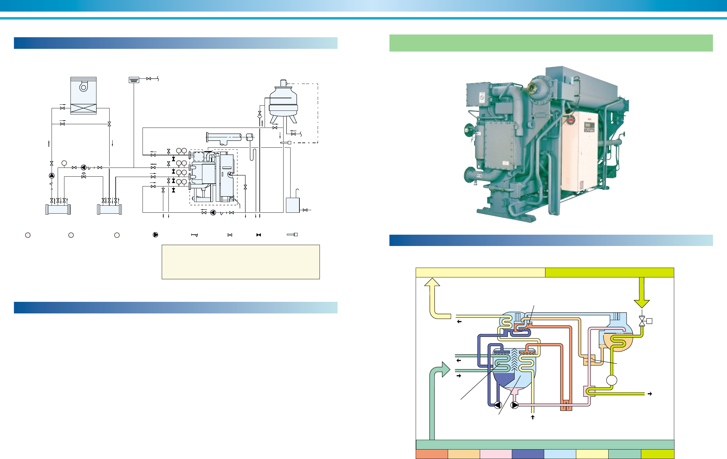
42 43
ENVIRONMENTALLY FRIENDLY TECHNOLOGY SUPER ABSORPTION
1. Equipment and parts outside the area surrounded by the broken line
are not supplied by SANYO.
2. Refer to the “Dimensions” for pipe connections and diameters.
3. Determine the locations of the chilled/hot water pumps, cooling
water pump and expansion tank in due consideration of the pump’s
hydrostatic head.
The chiller/heaters should not, as standard condition, be subject to a
pressure larger than 784kPa (8 kg/cm2G) at any water headers.
4. Concerning the temperature control of cooling water, refer to the
section of “control method of cooling water temperature”.
5. The chilled/hot and cooling water pumps should preferably be
provided exclusively for each chiller/heaters.
6. During heating operation, cooling water must be discharged.
7. Provide a thermometer and pressure gauge at the outlet and inlet of
the chilled/hot and cooling water pipe connections.
8. Provide an air vent valve in each of the chilled/hot and cooling water
lines at a point higher than each header.
9. Lay pipes from the cover of the evaporator, absorber and smoke
chamber to the drain ditch.
General remarks on piping work
10.Provide expansion tank in the chilled/hot water line.
11.Provide a bleeder in the cooling water line for control of water quality.
12.There should be a sufficiently large clearance for easy access to the
evaporator, absorber and condenser, to facilitate inspection and
cleaning work.
13.Provide heat insulation to the flue, which should be equipped with a
damper and condensate drain.
14.Do not connect the flue to the smoke stack of an incinerator.
15.When one flue is used for two or more chiller/heaters, a device
has to be provided to prevent the flow of exhaust gas into the one
which is out of operation.
16.The exhaust discharge end of the flue should be kept a sufficiently
large distance away from the cooling tower.
17.Provide a draft regulator if the static pressure inside the flue is
subject to fluctuations.
18.Fix the rupture disk on the chiller/heaters according to the manual of
rupture disk, if necessary.
19.All external water piping with JIS 10k welding flanges are to be
provided by the customer.
Typical piping diagram (DE)
Figure 32. Typical piping diagram
P T
P T
P T
P T
F
Air conditioner Expansion tank
Chiller / hot
water pump
(secondary)
Chilled / hot
water pump
(primary)
By-pass valve
Supply
header Return
header
Cooling water pump To drain ditch
Fuel
Air vent
Flue Water supply
T: Thermometer
COOLING
TOWER
HC C
Tank
above
1M
3
P: Pressure gauge F: Flow meter : Water pump : Strainer : Valve : Valve : Thermostat
In order to prevent freezing up of chilled water when the chiller/heaters
get a stop signal, continue the operation of the primary and secondary
chilled/hot water pumps and air conditioner during dilution cycle
operation of the chiller/heaters.
(about 15 minutes).
Cooling cycle schematic
Figure 33. Steam-fired chillers
Condenser
Low Temperature
Generator
Low Temperature
Heat Exchanger
Cooling Water
Chilled Water
Absorber
Evaporator
Cooling Water
High Temperature
Generator
Steam
SteamTrap
Steam Drain
High Temperature
Heat Exchanger
Heat Reclaimer
Refrigeration capacity 1.2
Heat 1.0
Chilled water
Steam
Liq. refrigerant Vap. refrigerant Cooling water
Heat sink 2.2
Dil. solution
Int. solution
Conc. solution
Steam-fired chillers
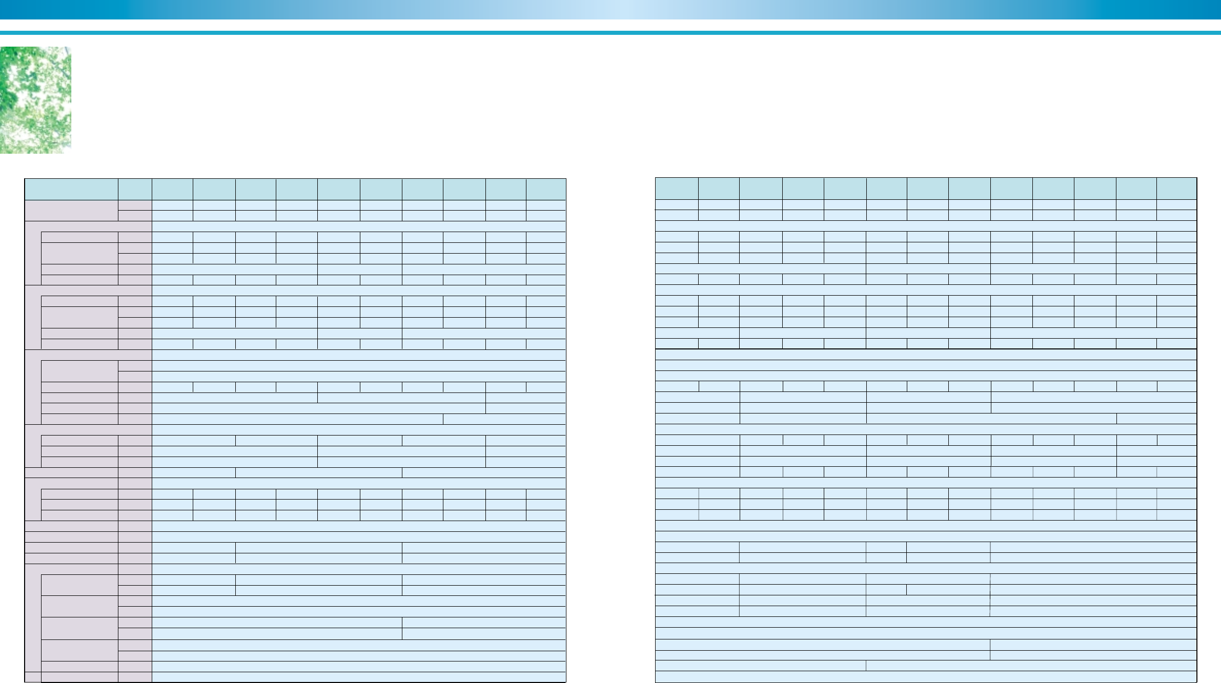
45
SUPER ABSORPTION
44
ENVIRONMENTALLY FRIENDLY TECHNOLOGY
Double effect steam-fired absorption chillers
Chilled water of 7°C is produced by high efficient double effect operation using steam of 784kPa or hot water of
190~200°C as its driving heat source. It is able to improve the balance of electricity and steam by means of effec-
tive use of turbine back pressure steam and surplus steam.
NE-11Unit
Model(TSA-NE-**) NE-12 NE-13 NE-14 NE-21 NE-22 NE-23 NE-24 NE-31 NE-32
◆ NE Model Specification
Refrigeration
capacity
Chilled water system
Cooling water system
Kind of steam
Supply pressure
Steam consumption
Steam connection (JIS)
Drain connection (JIS)
Control valve conn. (JIS)
Overall dimentions
Length (L)
Width (W)
Height (H)
Tube removal
Weights
Operation weight
Max shipping weight
Total Shipping weight
Shipping method
Electric Power
Total electric current
Apparent power
Electric data
Flow rate
Pressure drop
Connection (JIS)
Holding water volume
Flow rate
Pressure drop
Connection (JIS)
Holding water volume
No.1 ABS pump
No.2 ABS pump
REF pump
Purge pump
PD cell heater
Control circuit
(USRT)
kW
m3/h
(mH2O)
kPa
inch
liter
m3/h
(mH2O)
kPa
inch
m3
(kg/cm
2
G)
kPa
kg/h
inch
inch
inch
mm
mm
mm
mm
kgf
kgf
kgf
A
kVA
kW
A
kW
A
kW
A
kW
A
W
W
100 120 150 180 210 240 280 320 360 400
352 422 527 633 738 844 985 1,125 1,266 1,407
60.5 72.6 90.7 109 127 145 169 194 218 242
6.5 6.6 8.0 8.3 7.5 7.9 5.1 5.5 5.8 6.1
64 65 78 81 74 77 50 54 57 60
100 120 150 180 210 240 280 320 360 400
3.9 4.4 6.5 7.7 5.6 6.2 10.9 12.1 8.7 9.4
38 43 64 75 55 61 107 119 85 92
440 528 660 792 924 1,060 1,230 1,410 1,580 1,760
2 2-1/2 3
1 1-1/2
1-1/2 2
2,785 3,735 3,865 4,885 4,930
2,400 3,400 4,500
1,440 1,635 1,755
2,200 2,250 2,390
5 6 8
0.31 0.34 0.38 0.42 0.53 0.58 0.63 0.69 0.89 0.95
4,200 4,400 5,500 5,700 6,800 7,100 8,400 8,800 10,800 11,200
3,800 4,000 5,000 5,100 6,100 6,300 7,500 7,800 9,600 9,900
3,800 4,000 5,000 5,100 6,100 6,300 7,500 7,800 9,600 9,900
7.2 10.1 12.9
5.5 7.9 10.2
1.3 2.5 3.4
3.9 6.8 9.1
0.2 0.4
1.3 1.8
4 5 6
0.12 0.13 0.15 0.17 0.22 0.24 0.28 0.30 0.34 0.36
12 → 7℃(Fouling factor = 0.088m2℃ / kW(0.0001m2h℃ / kcal)・Max. working pressure 784kPa(8 kgf / cm2G))
32 → 37.5℃(Fouling factor = 0.088m2℃ / kW(0.0001m2h℃ / kcal)・Max. working pressure 784kPa(8 kgf / cm2G))
Saturated Steam
8.0
784
3 phase 380V 50Hz
1 section
0.4
1.1
38
300
***
***
NE-52NE-51NE-42NE-41 NE-53 NE-61 NE-62 NE-63 NE-71 NE-72 NE-73 NE-81 NE-82
450 500 560 630 700 800 900 1,000 1,100 1,200 1,300 1,400 1,500
1,582 1,758 1,969 2,215 2,461 2,813 3,165 3,516 3,868 4,220 4,571 4,923 5,274
272 302 339 381 423 484 544 605 665 726 786 847 907
5.2 5.5 4.6 6.2 8.1 5.7 7.6 9.9 6.2 7.8 9.6 7.8 9.5
51 54 45 61 79 56 74 97 61 76 94 76 93
0.46 0.48 0.65 0.71 0.77 0.99 1.06 1.13 1.41 1.51 1.61 1.83 1.94
10 12 14 16
1.11 1.19 1.87 2.01 2.14 2.79 2.97 3.15 3.67 3.90 4.11 4.51 4.76
1,980 2,200 2,470 2,780 3,080 3,520 3,960 4,400 4,840 5,280 5,720 6,160 6,600
13,200 13,600 18,800 20,400 21,900 26,600 28,500 30,500 36,200 38,200 40,500 43,600 46,100
11,600 11,900 16,300 17,700 19,000 22,800 24,500 26,200 24,600 25,800 27,300 29,100 30,700
11,600 11,900 16,300 17,700 19,000 22,800 24,500 26,200 24,600 25,800 27,300 29,100 30,700
12.9 22.6 28.0 32.0 40.7
10.2 18.2 22.6 25.9 33.0
9.1 13.4 15.0 19.0 24.0
3.4 3.7 5.5 7.5
0.4 0.75
1.1 1.9
38 76
1.8 3.0 3.7
5.4 9.1 12.0
4,940 5,185 5,725 6,225 5,840 6,335 6,865 6,430 6,960 7,460 6,960 7,460
4,500 4,600 5,100 5,600 5,200 5,700 6,200 6,000 6,500 7,000 6,500 7,000
3 4 5 6
1-1/2 2 2-1/2 3
2 2-1/2 3 4
1,975 2,300 2,500 3,000 3,200
2,600 2,900 3,330 3,450 3,650
Saturated Steam
8.0
784
1 section
0.4
1.8
300
3 phase 380V 50Hz
450 500 560 630 700 800 900 1,000 1,100 1,200 1,300 1,400 1,500
10.3 11.2 7.1 9.4 12.1 8.5 11.2 14.4 9.4 11.8 14.5 12.2 14.7
101 110 70 92 119 83 110 141 92 116 142 120 144
8 10 12 14
12 → 7℃(Fouling factor = 0.088m
2
℃ / kW(0.0001m
2
h℃ / kcal)・Max. working pressure 784kPa(8 kgf / cm
2
G))
32 → 37.5℃(Fouling factor = 0.088m
2
℃ / kW(0.0001m
2
h℃ / kcal)・Max. working pressure 784kPa(8 kgf / cm
2
G))
***
***
Specifications subject to change without notic
e.
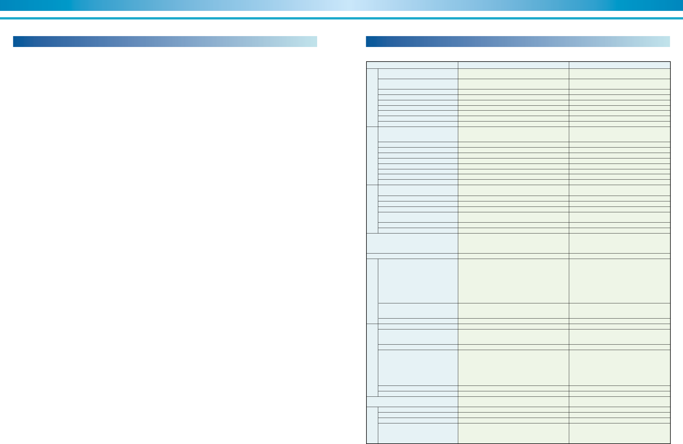
47
SUPER ABSORPTION
46
ENVIRONMENTALLY FRIENDLY TECHNOLOGY
The heating cycle
Item
Temperature
Flow rate
Max. working pressure
Hydraulic test pressure
Fouling factor
Material of tubes
Water quality
Structure of water header
Manufacturing standard of water header
Temperature
Flow rate
Max. working pressure
Hydraulic test pressure
Fouling factor
Material of tubes
Water quality
Structure of water header
Manufacturing standard of water header
Supply pressure
Steam consumption rate
Max. working pressure
Hydraulic test pressure
Material of tubes and steam quality
Structure of water header
Manufacturing standard of water header
Electricity
Shipment
Safety functions
Capacity control
Parts
Painting
Indication lamps
Display
External terminals
(no-voltage normal open contact)
Structure
Parts
Electrical wiring and piping
Place
Ambient temperature
Ambient humidity
Atmosphere
Option
Outlet : 5°C~12°C
Temperature difference : 3°C~10°C
Changes depending on chilled water temperature
difference (min. flow rate : 50%)
981~1,961kPa (10kg/cm2G~20kg/cm2G)
Max. working press.✕1.5 times
No option
No option
No option
No option
Inlet : 20.0°C~33.0°C
Within the water flow range of each model
981~1,961kPa (10kg/cm2G~20kg/cm2G)
Max. working press.✕1.5 times
Max. 0.196m2 °C/kW (0.0002m2h°C/kcal)
No option
No option
No option
No option
392kPa~784kPa Max. allowable super-heat :10°C
(4kg/cm2G~8kg/cm2G)
Changes depending on the specifications
No option
No option
No option
No option
TUV•ASME
Contact SANYO's representative
Multi-shipment
Cooling water flow switch
No option
No option
No option
No option
No option
No option
No option
No option
No option
No option
No option
No option
Standard
Inlet : 12.0°C
Outlet : 7.0°C
0.605m3/h•RT
784kPa (8kg/cm2G)
Max. working press.+196kPa (2kg/cm2)
0.088m2 °C/kW (0.0001m2h°C/kcal)
Material : copper tube
Refer to JRA-GL02E-1994
Removal type
SANYO standard
Inlet : 32.0°C
Outlet : 37.5°C
1.0m3/h•RT
784kPa (8kg/cm2G)
Max. working press.+196kPa (2kg/cm2)
0.088m2 °C/kW (0.0001m2h°C/kcal)
Material : copper tube
Refer to JRA-GL02E-1994
Removal type
SANYO standard
784kPa (8kg/cm2G) Saturated steam
4.4kg/h•RT
981kPa (10kg/cm2G)
1,471kPa (15kg/cm2G)
Material : 9/1 copper nickel
Quality : refer to JIS B-8223
Removal type
Japanese pressure vessel code
3 phase 380V 50Hz
(Voltage regulation : within ± 10%)
(Frequency regulation : within ± 5%)
One-section
•Refrigerant temperature supervision
•Chilled water freezing protection
•Chilled water flow switch
•Cooling water temperature supervision
•H.T. generator temperature supervision
•H.T. generator pressure supervision
•H.T. generator solution level supervision
•Crystalization protection
•Motor protection
•Digital PID control by chilled water outlet temperature
•Inverter control of No.1 absorbent pump
Selected by SANYO
Munsell 5Y-7/1
•Operation : red
•Stop : green
•Equipment alarm : orange
•LCD
•Operation indication
•Stop indication
•Alarm indication
•Answer back indication
Indoor type
Selected by SANYO
Wiring : 600V grade polyvinyl chloride-insulated wire
Pipe : plicatube (flexible metal conduit)
Indoor
5°C~40°C
Relative humidity : Max. 90% (45°C)
Be sure the following are not present:
•Corrosive gas
•Explosive gas
•Poisonous gas
Installation condition
Control panel Control Steam Cooling water Chilled water
Scope of order (NE)Scope of supply (NE)
1.Absorption chiller
(1) Lower shell
•Evaporator and refrigerant dispersion tray
•Absorber and absorbent dispersion tray
•Eliminators
(2) Heat exchangers
•High temperature (H.T.) heat exchanger
•Low temperature (L.T.) heat exchanger
(3) Upper shell
•Low temperature (L.T.) generator
•Condenser
•Eliminators
(4) High temperature (H.T.) generator
(5) Heat reclaimer
(6) Pumps
•Absorbent pump(s) with isolating valves
•Refrigerant pump with isolating valves
•Purge pump
(7) Control panel
•CE marking (if requested according to the regulation).
(8) Steam control valve
•Control valve (electric type)
•Shutoff valve
(9) Locally mounted controls and electric parts
•Temperature sensor
•H.T. generator solution level electrodes
•H.T. generator pressure gauge
(10) Purge unit
•Storage tank
•Ejector and liquid trap
•Piping and various manual valves
•Palladium cell with heater
(11) Interconnecting piping and wiring
(12) Initial charge
•Absorbent (lithium bromide)
•Refrigerant
•Inhibitor
(13) Painting
•Main unit: rust preventive painted
•Control panel: finish painted
(14) Accessories
•Operation manual : One set
•Washer (for fixing foundation bolts) : One set
•Manometer : One piece
•Gasket and sealant for rupture disk : One set
(if requested according to the regulation).
2.Factory test
Tests below are carried out in the SANYO factory.
•Check of external dimensions
•Leak test (vacuum side)
•Hydraulic pressure test for water and steam headers
•Electric insulation resistance test
•Dielectric breakdown test
•Function test only for electric circuit and safety devices
•Performance test (one unit is tested for performance when
several units of the same model are ordered for one project)
3.Scope of supply of the purchaser
(1) Unloading, transportation, and insurance depend on the indi-
vidual sales contractor between your company and SANYO
group.
(2) Foundations with foundation bolts.
(3) External chilled/water, cooling water, steam and drain
piping work including various safety valves. isolating valves,
etc.
(4) Rupture disk, flange of rupture disk, bolts, nuts, piping work
and tank, etc, if necessary.
(5) External wiring and piping for the chillers including
necessary parts.
(6) Insulation for the chillers including necessary parts.
(7) Mating flanges, gaskets, bolts and nuts
•Steam inlet nozzle flange for H.T. generator steam header.
•Steam drain outlet nozzle flange.
•Inlet/outlet nozzle flanges for chilled water. (evaporator)
•Inlet/outlet nozzle flanges for cooling water. (absorber/condenser)
(8) Finish painting of the chillers.
(9) Cooling water inlet temperature control device.
(10) Furnishing air-piping* and electric wiring/piping of steam
control valve including necessary parts.
(11) Various temp./press. gauges for steam and water lines.
(12) Steam drain tank.
(13) Cooling tower(s), chilled water pump(s) and cooling water
pump(s) and its auxilialy accessaries.
(14) Electric power supply (specified value).
(15) Supply of chilled water, cooling water, steam and air* at rated
conditions.
(16) Necessary tools, workers and materials for installation and
site test operation.
(17)
After-sales service and periodical maintenance of the chillers.
(18) Any other item not specifically mentioned in the scope of
supply.
Note: *For electric-pneumatic valve only.
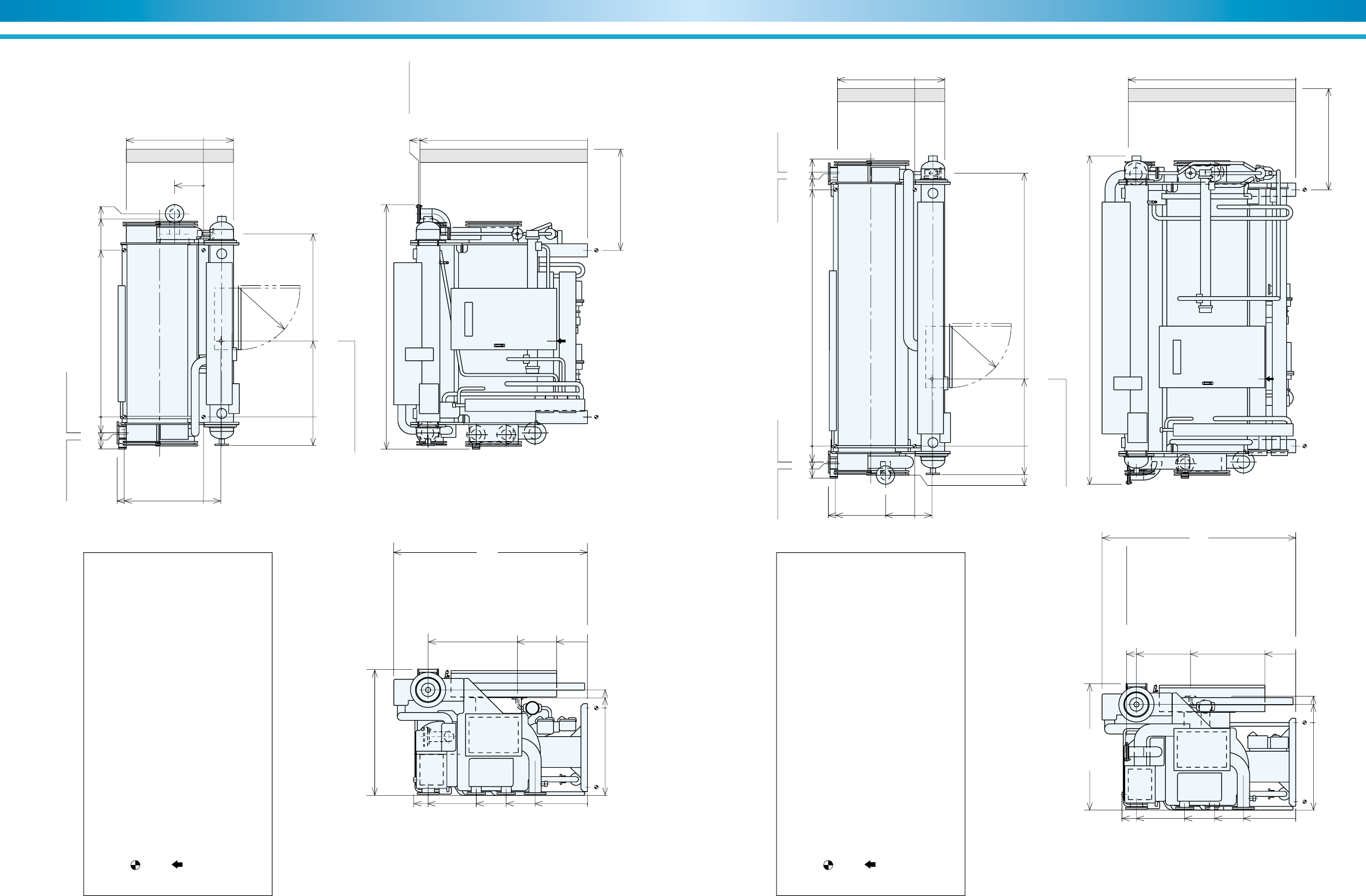
49
SUPER ABSORPTION
48
ENVIRONMENTALLY FRIENDLY TECHNOLOGY
Figure 34. NE-11 Thru NE-12
NOTES
1. Dimensions (L), (W), (H) are for the unit with rupture disk.
The dimensions are changed if additional parts are added.
2. indicates the position of anchor bolts.
3. All external water piping with welded JIS 10K flanges are to be provided by
the customer.
4. indicates the position of the power supply connection on control panel.
(diameter 33 mm)
5. Service space:
Longitudinal distance –1000 mm
Top –200 mm
Others –500 mm
6. Regarding fuel connection diameter and position, refer to specifications.
1440(W)
2785(L)
2400
(Tube removal space either side)
2200
(H)
1810
1921
877
341
329
0
Rupture Disk
4 inch
1904
0
796
350
0
995
0
116
207
982
900
0
195
R700
1809
1974
1263
923
595
0
COW outlet
5 inch
COW inlet
5 inch
CHW outlet
4 inch
CHW in / out COW in / out
CHW inlet
4 inch
Steam inlet
2 inch
232
0
865
2084
364
200
180
1896
2253
2311
Wire connection ø33 hole
0
Figure 35. NE-13 Thru NE-14
NOTES
1. Dimensions (L), (W), (H) are for the unit with rupture disk.
The dimensions are changed if additional parts are added.
2. indicates the position of anchor bolts.
3. All external water piping with welded JIS 10K flanges are to be provided by
the customer.
4. indicates the position of the power supply connection on control panel.
(diameter 33 mm)
5. Service space:
Longitudinal distance –1000 mm
Top –200 mm
Others –500 mm
6. Regarding fuel connection diameter and position, refer to specifications.
1440(W) 3735(L)
3400
(Tube removal space either side)
2200
(H)
1921
1810
877
341
0
1904
0
1196
350
0
995
0
207
300
982
900
0
195
R700
1809
1975
1263
923
595
0
COW outlet
5 inch
COW inlet
5 inch
CHW outlet
4 inch
COW out CHW in
CHW out COW in
CHW inlet
4 inch
Rupture Disk
4 inch
Drain outlet
4 inch
Steam inlet
2 inch
323
328
0
765
3104
364
200
180
2916
3096
3116
3264
Wire connection ø33 hole
0
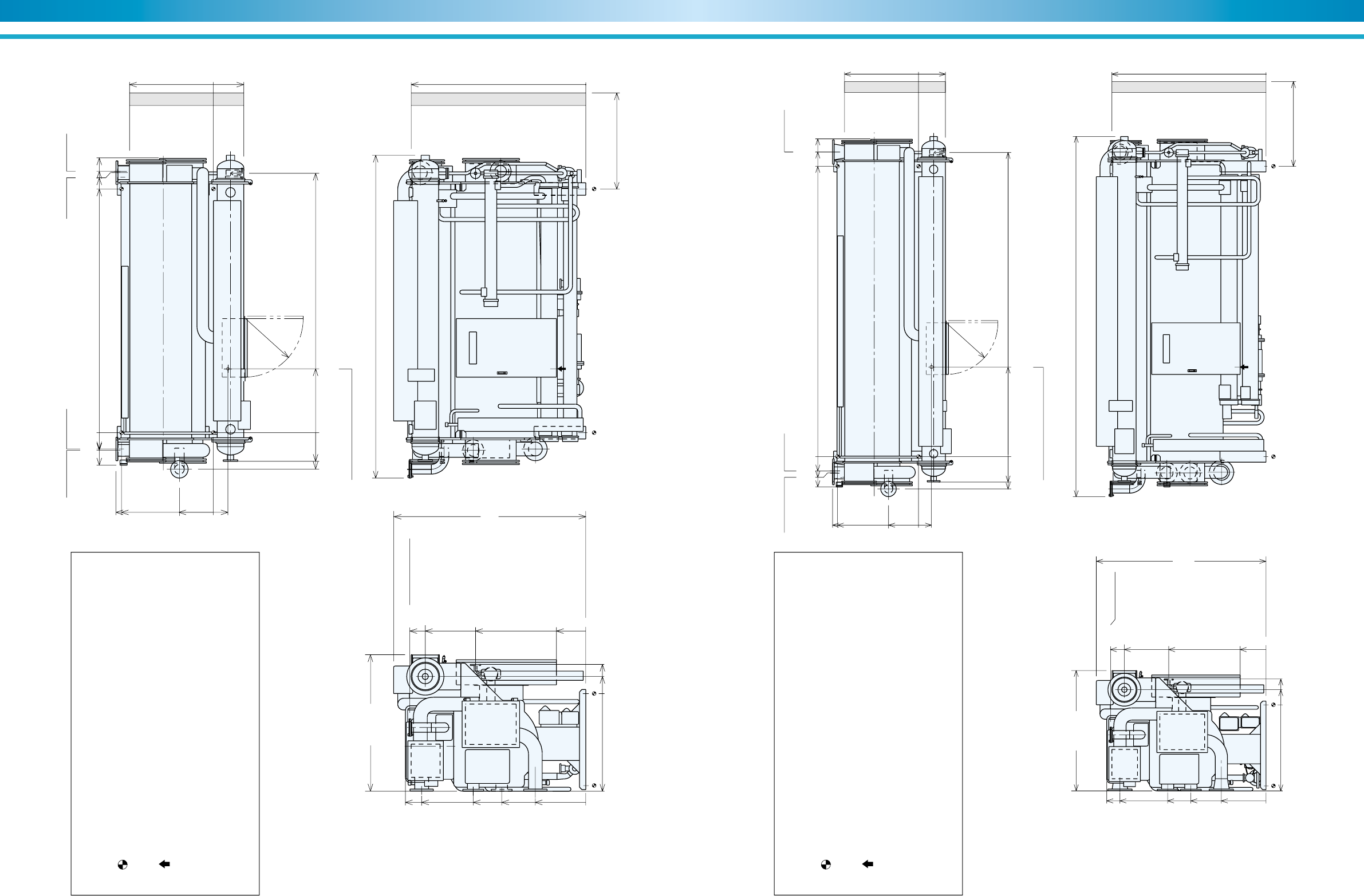
51
SUPER ABSORPTION
50
ENVIRONMENTALLY FRIENDLY TECHNOLOGY
Figure 36. NE-21 Thru NE-22
NOTES
1. Dimensions (L), (W), (H) are for the unit with rupture disk.
The dimensions are changed if additional parts are added.
2. indicates the position of anchor bolts.
3. All external water piping with welded JIS 10K flanges are to be provided by
the customer.
4. indicates the position of the power supply connection on control panel.
(diameter 33 mm)
5. Service space:
Longitudinal distance –1000 mm
Top –200 mm
Others –500 mm
6. Regarding fuel connection diameter and position, refer to specifications.
1635(W) 3865(L)
3400
(Tube removal space either side)
2250
(H)
2106
1840
1003
364
0
2089
0
1319
350
0
1168
0
205
350
1165
1100
0
175
406
R700
1964
2159
1346
1006
603
0
COW outlet
6 inch
COW inlet
6 inch
CHW outlet
5 inch
COW out CHW in
CHW out COW in
CHW inlet
5 inch
Rupture Disk
4 inch
Drain outlet
1 inch
Steam inlet
2-1/2 inch
343
438
0
765
3104
390
212
195
2916
3111
3128
3289
Wire connection ø33 hole
0
Figure 37. NE-23 Thru NE-24
NOTES
1. Dimensions (L), (W), (H) are for the unit with rupture disk.
The dimensions are changed if additional parts are added.
2. indicates the position of anchor bolts.
3. All external water piping with welded JIS 10K flanges are to be provided by
the customer.
4. indicates the position of the power supply connection on control panel.
(diameter 33 mm)
5. Service space:
Longitudinal distance –1000 mm
Top –200 mm
Others –500 mm
6. Regarding fuel connection diameter and position, refer to specifications.
1635(W) 4885(L)
4500
(Tube removal space either side)
2250
(H)
2106
1840
1003
364
0
2089
0
1319
350
0
1168
0
205
350
1165
1100
0
175
406
R700
1980
2159
1333
1019
605
0
COW outlet
8 inch
COW inlet
8 inch
CHW outlet
6 inch
COW outCHW in / out COW in
CHW inlet
6 inch
Rupture Disk
4 inch
Drain outlet
1 inch
Steam inlet
2-1/2 inch
345
438
0
1215
4124
411
221
195
3936
4131
4309
Wire connection ø33 hole
0
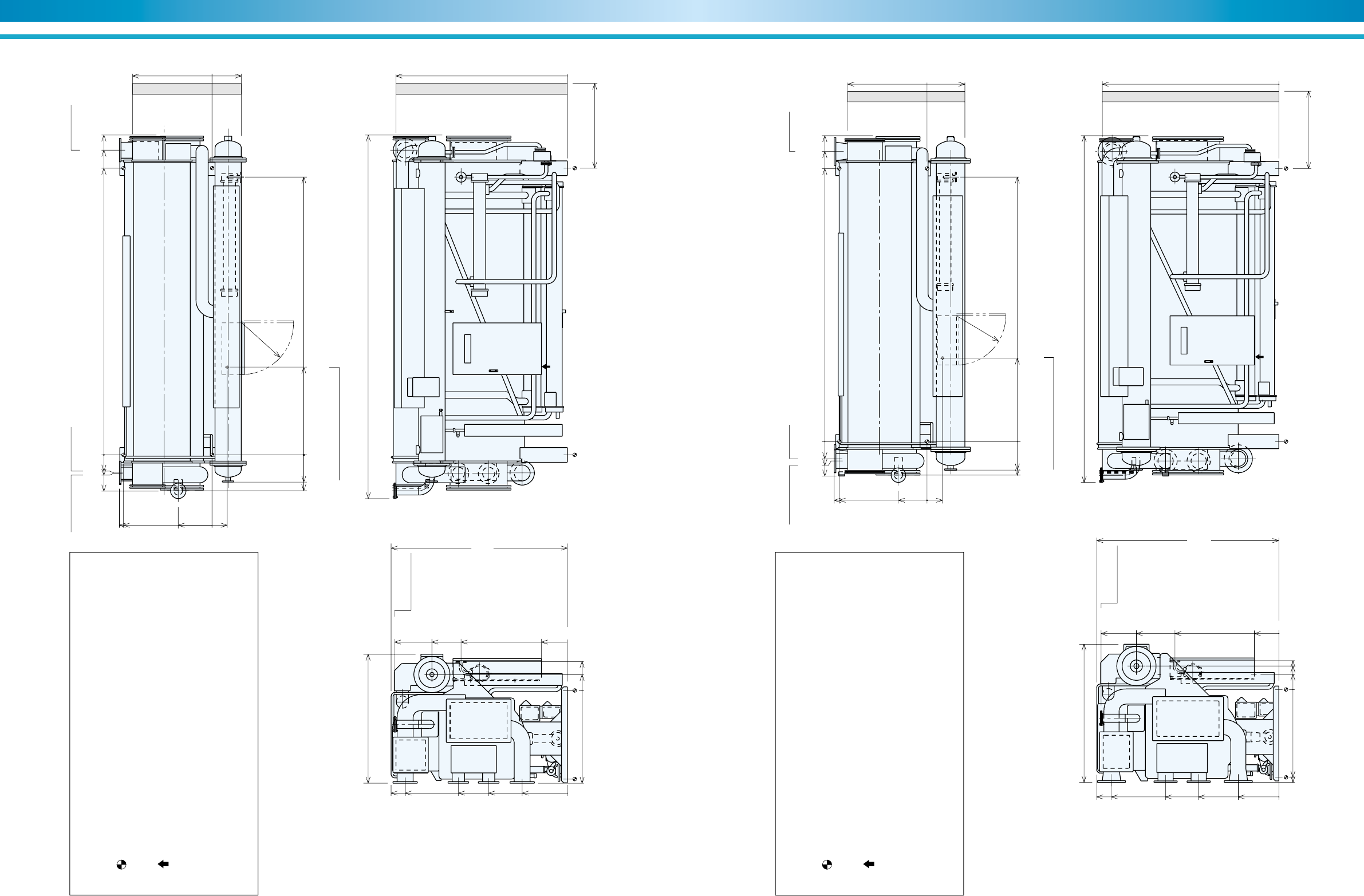
53
SUPER ABSORPTION
52
ENVIRONMENTALLY FRIENDLY TECHNOLOGY
Figure 38. NE-31 Thru NE-32
NOTES
1. Dimensions (L), (W), (H) are for the unit with rupture disk.
The dimensions are changed if additional parts are added.
2. indicates the position of anchor bolts.
3. All external water piping with welded JIS 10K flanges are to be provided by
the customer.
4. indicates the position of the power supply connection on control panel.
(diameter 33 mm)
5. Service space:
Longitudinal distance –1000 mm
Top –200 mm
Others –500 mm
6. Regarding fuel connection diameter and position, refer to specifications.
1755(W) 4930(L)
4500
(Tube removal space either side)
2390
(H)
2340
1910
1078
396
0
2323
0
1440
350
0
1256
0
218
396
1256
1200
0
205
458
R700
2198
2390
1476
1066
611
0
COW outlet
8 inch
COW inlet
8 inch
CHW outlet
6 inch
COW outCHW in / out COW in
CHW inlet
6 inch
Rupture Disk
4 inch
Drain outlet
1-1/2 inch
Steam inlet
3 inch
370
488
0
1190
3766
492
250
245
3886
4131
4336
Wire connection ø33 hole
0
Figure 39. NE-41 Thru NE-42
NOTES
1. Dimensions (L), (W), (H) are for the unit with rupture disk.
The dimensions are changed if additional parts are added.
2. indicates the position of anchor bolts.
3. All external water piping with welded JIS 10K flanges are to be provided by
the customer.
4. indicates the position of the power supply connection on control panel.
(diameter 33 mm)
5. Service space:
Longitudinal distance –1000 mm
Top –200 mm
Others –500 mm
6. Regarding fuel connection diameter and position, refer to specifications.
1975(W) 4940(L)
4500
(Tube removal space either side)
2600
(H)
2531
2060
1132
538
0
2513
0
1480
350
0
1321
1250
0
220
411
335
1321
1250
0
220
407
R700
2383
2600
1613
1142
577
0
COW outlet
8 inch
COW inlet
8 inch
CHW outlet
6 inch
COW outCHW in / out COW in
CHW inlet
6 inch
Rupture Disk
4 inch
Drain outlet
1-1/2 inch
Steam inlet
3 inch
407
478
0
1190
3766
492
276
244
3886
4130
4354
Wire connection ø33 hole
0
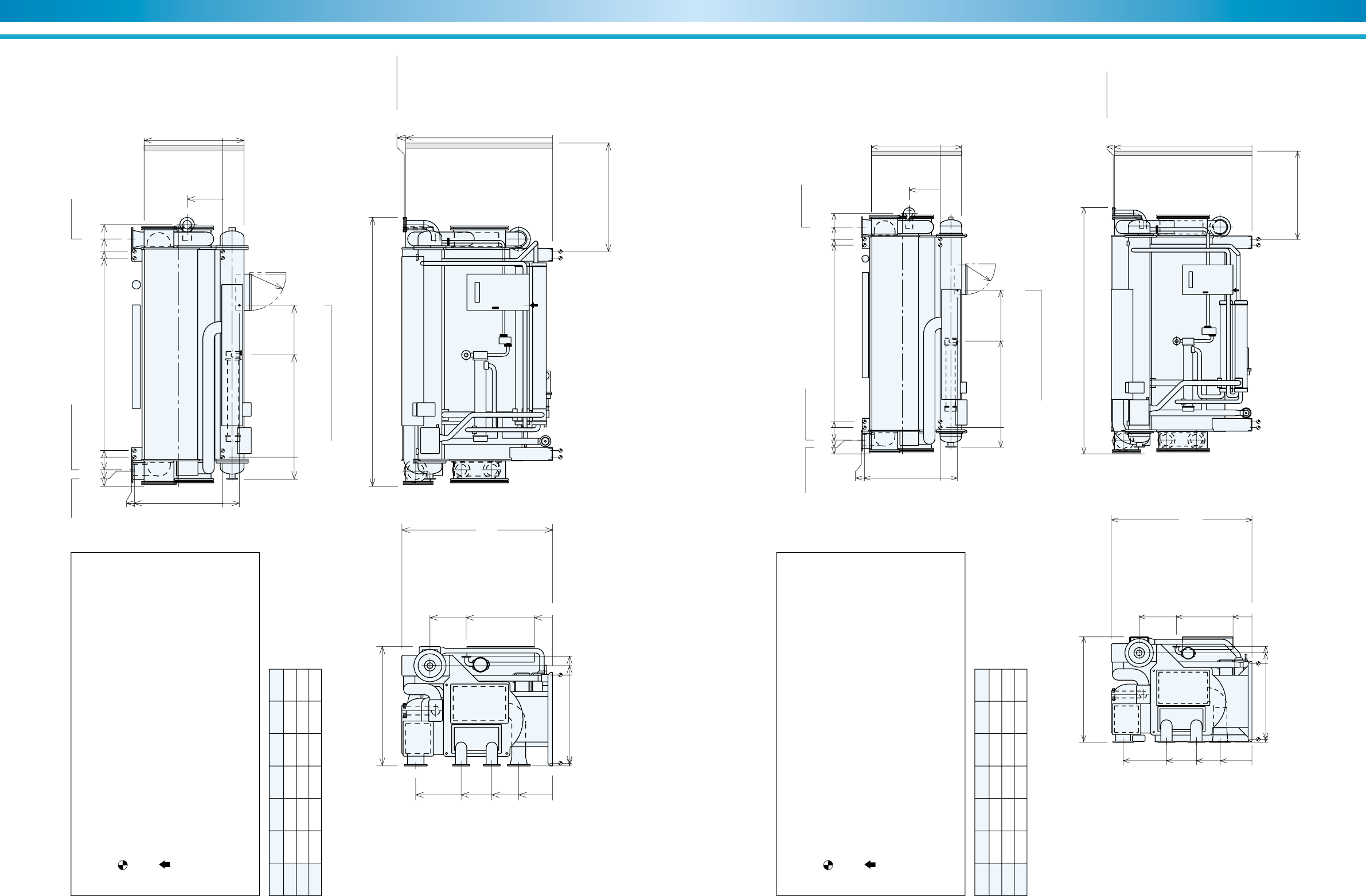
55
SUPER ABSORPTION
54
ENVIRONMENTALLY FRIENDLY TECHNOLOGY
Model A B C D E L
NE-51 3836 3966 4206 4482 4600 5185
NE-52 4378 4508 4748 5024 5100 5725
NE-53 4876 5006 5246 5522 5600 6225
Figure 40. NE-51 Thru NE-53
NOTES
1. Dimensions (L), (W), (H) are for the unit with rupture disk.
The dimensions are changed if additional parts are added.
2. indicates the position of anchor bolts.
3. All external water piping with welded JIS 10K flanges are to be provided by
the customer.
4. indicates the position of the power supply connection on control panel.
(diameter 33 mm)
5. Service space:
Longitudinal distance –1000 mm
Top –200 mm
Others –500 mm
6. Regarding fuel connection diameter and position, refer to specifications.
2300(W)
L
E
(Tube removal space either side)
2900
(H)
2360
1665
1515
410
0
684
2855
2825
0
350
0
1321
1250
0
220
411
1750
1700
0
320
R700
2635
1760
1170
651
0
COW outlet
12 inch
COW inlet
12 inch
CHW outlet
8 inch
COW out CHW in / out COW in
CHW inlet
8 inch
Drain outlet
2 inch
Steam inlet
4 inch
421
0
1971
2930
560
265
240
130
Wire connection ø33 hole
0
Rupture Disk
6 inch
AB C D
Model A B C D E L
NE-61 4326 4466 4756 5076 5200 5840
NE-62 4826 4966 5256 5574 5700 6335
NE-63 5351 5491 5781 6099 6200 6865
Figure 41. NE-61 Thru NE-63
NOTES
1. Dimensions (L), (W), (H) are for the unit with rupture disk.
The dimensions are changed if additional parts are added.
2. indicates the position of anchor bolts.
3. All external water piping with welded JIS 10K flanges are to be provided by
the customer.
4. indicates the position of the power supply connection on control panel.
(diameter 41 mm)
5. Service space:
Longitudinal distance –1000 mm
Top –200 mm
Others –500 mm
6. Regarding fuel connection diameter and position, refer to specifications.
2500(W) L
E
(Tube removal space either side)
3330
(H)
2670
1785
1635
500
0
736
3286
3260
0
450
0
1870
1800
0
250
406
1870
1800
0
400
R700
3050
2025
1315
753
0
COW outlet
14 inch
COW inlet
14 inch
CHW outlet
10 inch
COW out CHW in / out COW in
CHW inlet
10 inch
Drain outlet
2-1/2 inch
Steam inlet
5 inch
463
0
2054
3260
622
310
295
140
Wire connection ø41 hole
0
Rupture Disk
6 inch
AB C D
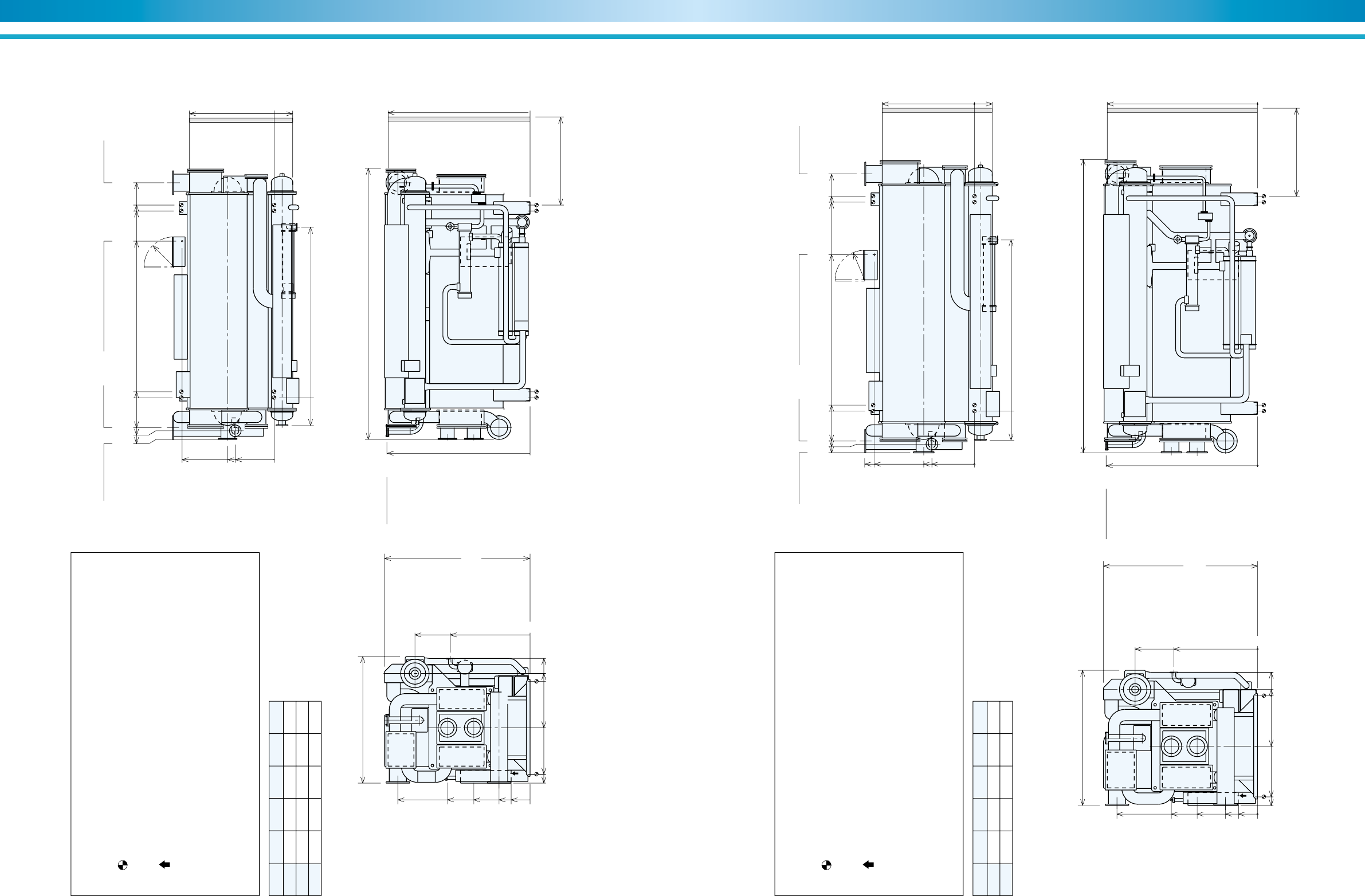
57
SUPER ABSORPTION
56
ENVIRONMENTALLY FRIENDLY TECHNOLOGY
Model A B C D L
NE-71 4426 4566 5096 6000 6430
NE-72 4951 5091 5621 6500 6960
NE-73 5451 5591 6121 7000 7460
Figure 42. NE-71 Thru NE-73
NOTES
1. Dimensions (L), (W), (H) are for the unit with rupture disk.
The dimensions are changed if additional parts are added.
2. indicates the position of anchor bolts.
3. All external water piping with welded JIS 10K flanges are to be provided by
the customer.
4. indicates the position of the power supply connection on control panel.
(diameter 41 mm)
5. Service space:
Longitudinal distance –1000 mm
Top –200 mm
Others –500 mm
6. Regarding fuel connection diameter and position, refer to specifications.
3000(W)
L
D
(Tube removal space either side)
3450
(H)
2730
1892
2005
440
0
3370
0
0
2410
2200
0
189
1100
547
2180
1100
920
3395
0
0
R700
3050
1960
1335
735
450
0
COW outlet
16 inch
COW inlet
16 inch
CHW outlet
12 inch
CHW in / out COW out COW in
CHW inlet
12 inch
Drain outlet
3 inch
Steam inlet
6 inch
663
0
4044
990
786
710
140
3710
Wire connection ø41 hole
0
Rupture Disk
6 inch
AB C
Model A B C D L
NE-81 4951 5091 5621 6500 6960
NE-82 5451 5591 6121 7000 7460
Figure 43. NE-81 Thru NE-82
NOTES
1. Dimensions (L), (W), (H) are for the unit with rupture disk.
The dimensions are changed if additional parts are added.
2. indicates the position of anchor bolts.
3. All external water piping with welded JIS 10K flanges are to be provided by
the customer.
4. indicates the position of the power supply connection on control panel.
(diameter 41 mm)
5. Service space:
Longitudinal distance –1000 mm
Top –200 mm
Others –500 mm
6. Regarding fuel connection diameter and position, refer to specifications.
3200(W)
L
D
(Tube removal space either side)
3650
(H)
2900
1982
2185
425
0
3560
0
0
2610
2400
0
146
1200
555
2370
2600
1200
1006
3587
0
0
R700
3330
2040
1430
757
450
0
COW outlet
16 inch
COW inlet
16 inch
CHW outlet
14 inch
CHW in / out COW out COW out
CHW inlet
14 inch
Drain outlet
3 inch
Steam inlet
6 inch
690
0
4044
990
785
710
140
3710
Wire connection ø41 hole
0
Rupture Disk
6 inch
AB C
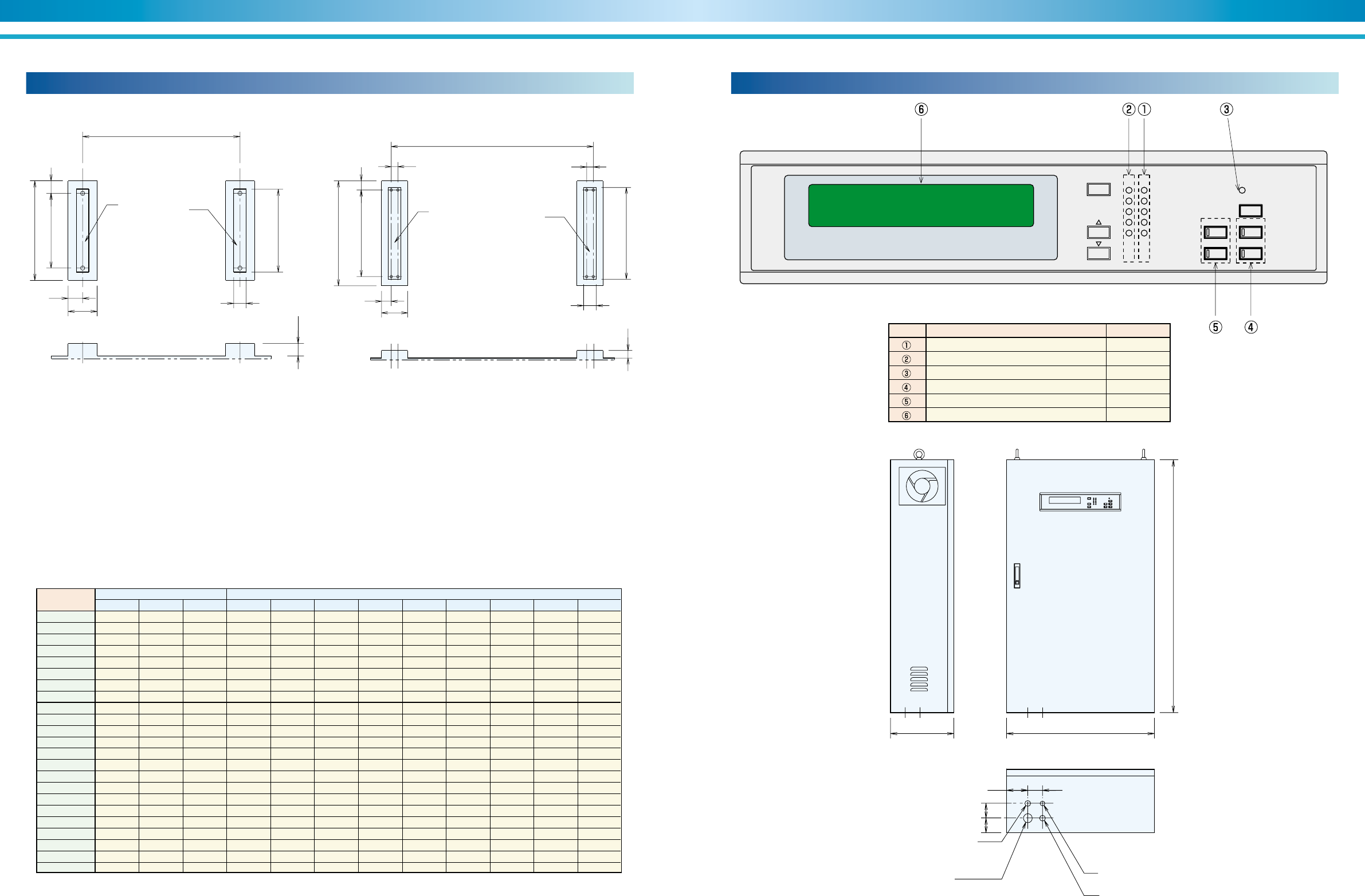
59
SUPER ABSORPTION
58
ENVIRONMENTALLY FRIENDLY TECHNOLOGY
Name Lamp color
Running(Operation) indication lamp Red
Stop indication lamp Green
Alarm indication lamp Orange
Remote / Local select button with lamp Red
Mode select button with lamp Red
Data display LED
symbol
Control panel (NE)Foundation dimensional data (NE)
Table 10. Dimensional data
Figure 45. NE-51 Thru NE-82
Model
No.
Weight (kg) Dimensions (mm)
4,200 2,100 2,100 1,896 —175 350 900 150 1,200 150 1,000
4,400 2,200 2,200 1,896 —175 350 900 150 1,200 150 1,000
5,500 2,700 2,750 2,916 —175 350 900 150 1,200 150 1,000
5,700 2,850 2,850 2,916 —175 350 900 150 1,200 150 1,000
6,800 3,400 3,400 2,916 —175 350 1,100 150 1,400 150 1,200
7,100 3,550 3,550 2,916 —175 350 1,100 150 1,400 150 1,200
8,400 4,200 4,200 3,939 —175 350 1,100 150 1,400 150 1,200
8,800 4,400 4,400 3,939 —175 350 1,100 150 1,400 150 1,200
10,800 5,400 5,400 3,886 —200 400 1,200 150 1,500 200 1,300
11,200 5,600 5,600 3,886 —200 400 1,200 150 1,500 200 1,300
13,200 6,600 6,600 3,886 —200 400 1,250 150 1,550 200 1,350
13,600 6,800 6,800 3,886 —200 400 1,250 150 1,550 200 1,350
18,800 9,400 9,400 3,966 130 190 510 1,700 180 2,060 250 1,800
20,400 10,200 10,200 4,508 130 190 510 1,700 180 2,060 250 1,800
21,900 10,950 10,950 5,006 130 190 510 1,700 180 2,060 250 1,800
26,600 13,300 13,300 4,466 140 210 560 1,800 180 2,160 300 1,900
28,500 14,250 14,250 4,966 140 210 560 1,800 180 2,160 300 1,900
30,500 15,250 15,250 5,491 140 210 560 1,800 180 2,160 300 1,900
36,200 18,100 18,100 4,566 140 210 560 2,200 180 2,560 300 2,300
38,200 19,100 19,100 5,091 140 210 560 2,200 180 2,560 300 2,300
40,500 20,250 20,250 5,591 140 210 560 2,200 180 2,560 300 2,300
43,600 21,800 21,800 5,091 140 210 560 2,400 180 2,760 300 2,500
46,100 23,050 23,050 5,591 140 210 560 2,400 180 2,760 300 2,500
NE-11
NE-12
NE-13
NE-14
NE-21
NE-22
NE-23
NE-24
NE-31
NE-32
NE-41
NE-42
NE-51
NE-52
NE-53
NE-61
NE-62
NE-63
NE-71
NE-72
NE-73
NE-81
NE-82
Oper.
AA BB A B C D E F G J K
150
A
G
E F
D
C
AA BB
J
K
150
A
BB
D
C
EF
G
J
K
AA BB
MODE
SETTING
STOP RUN
CHILLER
BUZZER STOP
STOP LOCAL
REMOTE
OPERATION
ALARM
REF PUMP
#1 ABS PUMP
#2 ABS PUMP
PURGE PUMP
H Generator temp 149.9°C
70100
7070
1200
700300
Remote control ø27
Steam shutoff valve ø21
Power supply
NE-11 thru NE-53 : ø33
NE-61 thru NE-82 : ø41
Steam control valve
NE-11 thru NE-53 : ø21
NE-61 thru NE-82 : ø27
Figure 44. NE-11 Thru NE-42
Figure 46. Control panel
NOTES :
1. The base of machine has ø50 hole for anchor bolt.
2. Anchor bolt should be fixed by shown detail drawing.
Washer should be welded with base.(Refer to Figure 21 page32)
3. There should be a drain ditch around the foundation.
4. The floor surface should be made as water proof for ease of
maintenance work.
5. Surface of foundation should be made flat.
6. Anchor bolts and nuts are supplied by customer.
Table 11. Indication lamp
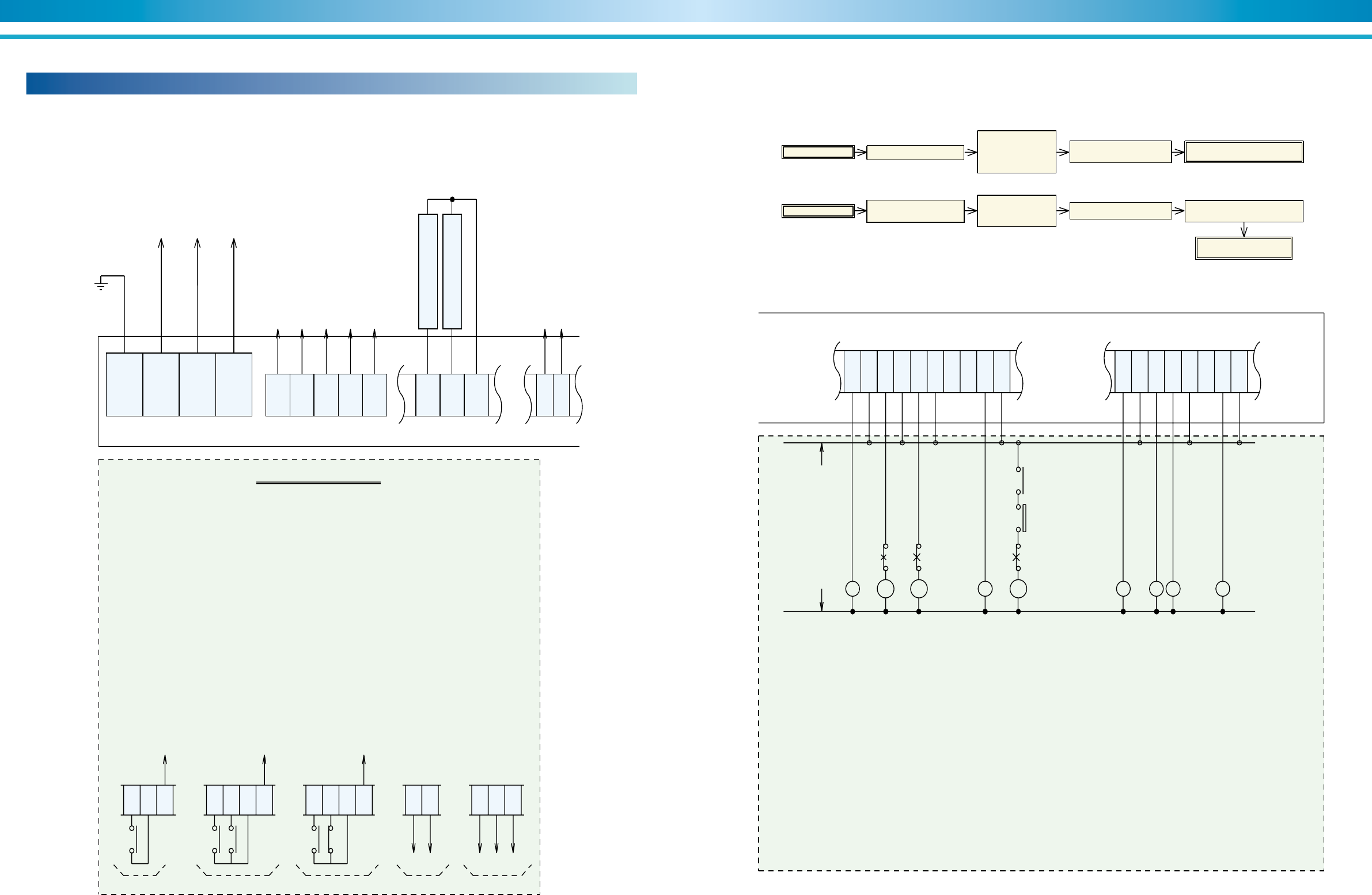
61
SUPER ABSORPTION
60
ENVIRONMENTALLY FRIENDLY TECHNOLOGY
Field wiring (NE)
Figure 47. Typical electrical field connection diagram - Steam-fired (NE)
Chilled water
pump interlock
To power source
3 Ph,50/60Hz
380V, 400V, 415V, 440V
E
R0
S0
T0
(52CH)
171
Cooling water
pump interlock
(52CO)
136
135
1
2
3
4
10
For emergency stop signal
(Those terminals are
connected by jumper)
Remove the jumper
before using
those terminals
The unit can be operated by the following five type signal.
(1)Non-voltage normal open contact(A) for start & stop (DC24V 10mA).
:Wiring the terminal 330 and 333.
(2)Non-voltage normal open contact(A) for start (DC24V 10mA).
:Wiring the terminal 330 and 333.
Non-voltage normal open contact(A) for stop (DC24V 10mA).
:Wiring the terminal 331 and 333.
(3)Non-voltage normal open contact(A) for start (DC24V 10mA).
:Wiring the terminal 330 and 333.
Non-voltage normal close contact(B) for stop (DC24V 10mA).
:Wiring the terminal 331 and 333.
(4)Continuous signal of DC/AC 24V for start & stop.
:Wiring the terminal 330 and 332.(Those terminals are non-polarity.)
(5)Pulse signal of DC/AC 24V for start.
:Wiring the terminal 330 and 332.(Those terminals are non-polarity.)
Signal of DC/AC 24V for stop.
:Wiring the terminal 331 and 332.(Those terminals are non-polarity.)
Remote signal
330
A
DC/AC 24VDC/AC 24V
Terminal strips in the control panel
(4)(1) (5)
4Y
1
333
332
171 171
330
A
(2)
4Y
1
331
333
332
4Y
2
AB
4Y
2
332
4Y
1
331
333
(3)
A
330
330
332
330
332
331
171
COM
84
85
For message signal
Terminal strips in the control panel
LL
Max. voltage and
Max. current
:AC 250V,0.1A
Stop
indication
Operation
indication
Answer back
indication
52
CT
Chilled
water pump
52
CH
51
CH 51
CT
Cooling tower
fan
52
CO
23
CO
51
CO
52
CO
Cooling water
pump
Note
1.Be sure to insert 23CO at the cooling water inlet side.
2.Be sure to wire the 52CH(interlock) between terminals 171 and 136.
3.Be sure to wire the 52CO(interlock) between terminals 171 and 135.
4.Be sure to wire the chilled water pump control relay between terminals 302 and 303
5.Be sure to wire the cooling water pump control relay between terminals 304 and 305.
L :Indication lamp
51CH:Chilled water pump overcurrent relay
51CO:Cooling water pump overcurrent relay
51CT :Cooling tower fan overcurrent relay
23CO:Cooling tower fan thermostat
Symbols
Start/Stop sequence of auxiliary equipments
Start
Start signal
Machine operates
Chilled water pump operates
Stop air conditioners
Cooling water pump
operates and then
cooling tower fan
operates
Stop
Stop signal
Diluted operation start Chiller stops entirely
Cooling water pump
stops and cooling
tower fan stops
Operate air conditioners
L
Chilled water pump stops
300
301
302
303
304
305
306
307
308
309
320
321
322
323
324
325
326
327
L
Remote signal
indication
L
Alarm
indication
L
Buzzer signal
indication
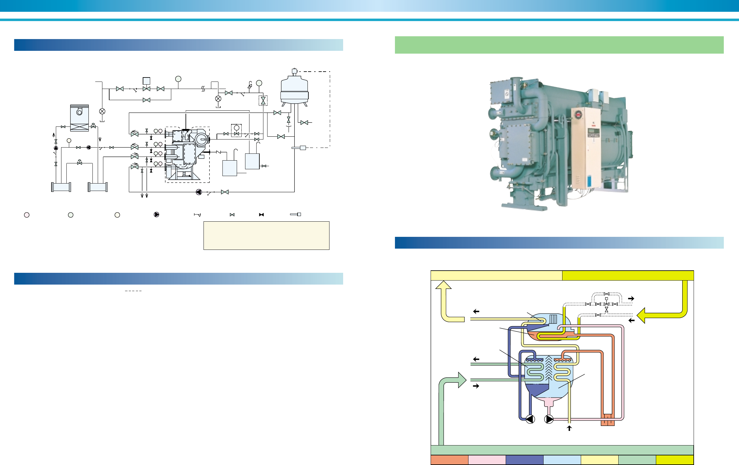
63
SUPER ABSORPTION
62
ENVIRONMENTALLY FRIENDLY TECHNOLOGY
1. Work outside the area surrounded by this line shall be under-
taken at the expense of the owner.
2. Refer to the Dimensions diagrams and specification tables for pipe
connections and diameters.
3. Standard supply steam press. Is 784 kPa (8 kg/cm2G). A reducing
valve and safety valve which blows at 981kPa (10 kg/cm2G) should
be located near the machine as in above diagram if the supply pres
sure is higher than 784kPa (8 kg/cm2G). A pipe should be extended
from this safety valve to release excess steam outdoors.
4. Even if a reducing valve is not required, a strainer, pressure gauge
and drain trap should be provided for each machine near the steam
inlet.
5. The back pressure in the steam drain line should be limited to less
than 49Pa (5 mH2O).
6. Determine the locations of the chilled water pumps and cooling water
pumps in due consideration of the pump’s hydrostatic head.
As standard condition, the machine should not be subject to a
pressure larger than 784kPa (8 kg/cm2G) at any water headers.
7. Concerning the temperature control of cooling water, refer to the
section of “control method of cooling water temperature”.
8. Provide a thermometer and pressure gauge at the outlet and inlet of
cooling water and chilled water.
General remarks on piping-laying work
9. Provide an air vent valve in each of the chilled and cooling water lines
at a point higher than the header for chilled water and cooling water.
10.Lay pipes from the cover of the evaporator and absorber to the drain
ditch.
11.Provide a bleeder in the cooling water line for control of water quality.
12.All external water piping with JIS 10k welding flanges are to be
provided by the customer.
13.Be sure to provide a shut-off valve to prevent the steam flow into the
chiller during shut-down.
In case two or more chillers are installed, provide an automatic
shut-off valve.
14.Be sure to design the location of cooling tower to prevent
contamination of cooling water by exhaust gas from flues.
15.Fix the rupture disk on the chiller according to the manual of rupture
disk, if necessary.
16.The chilled and cooling water pumps should preferably be provided
exclusively for each chillers.
17.Provide expansion tank in the chilled water line.
18.There should be a sufficiently large clearance for easy access to the
evaporator, absorber and condenser, to facilitate inspection and
cleaning work.
MV
HC C
By-pass
valve
Supply
header Return
heater
F
Air conditioner
Chilled water
pump
(primary)
Chilled water pump
(secondary)
Steam
control valve
To boiler
Cooling
water pump
Cooling water
thermostat
Water
supply
Safety valve
Bleeder
valve
Bypass
valve
To drain ditch
Reducing valve
R
Main steam piping
Check valve
T
Tank
about
1m3
Steam
shutoff
valve
P
T
P
T
P
T
P
PP
In order to prevent freezing up of chilled water during
diluting operation of chiller, continue the operation of
the chilled water pumps and air conditioner until the
diluting operation is completed.
T: Thermometer P: Pressure gauge F: Flow meter : Water pump : Strainer : Valve : Valve : Thermostat
Typical piping diagram-laying (NE)
Figure 48. Typical piping diagram
Cooling cycle schematic
Figure 49. Hot water-fired chillers
Condenser
Generator
Absorber
Heat Exchanger
Cooling Water
Chilled Water
Evaporator
Cooling Water
Hot Water
Heat 1.0
Liq. refrigerant Vap. refrigerant Cooling water Chilled water Hot water
Refrigeration capacity 0.7
Heat sink 1.7
Dil. solutionConc. solution
Hot water-fired chillers
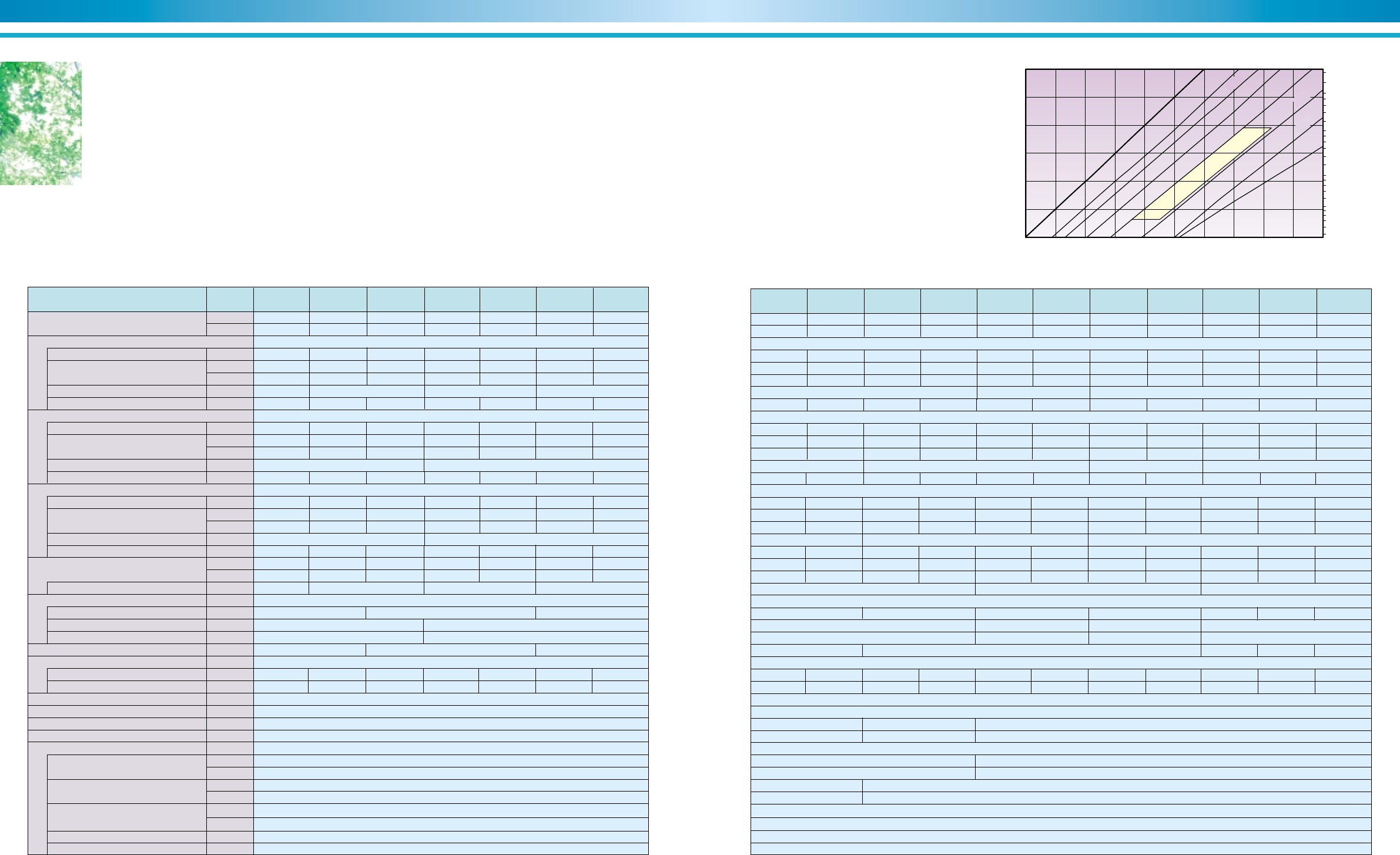
65
SUPER ABSORPTION
64
ENVIRONMENTALLY FRIENDLY TECHNOLOGY
Hot water-fired absorption chillers
Chilled water of 8°C can be produced using waste hot water of 80°C to 95°C from gas engine etc. It is a chiller
driven by waste hot water which temperature is low. Waste hot water and unused energy can be effectively used
and it is suitable for combined heat and power system.
LE-01Unit
Model(TSA-LE-**) LE-02 LE-03 LE-11 LE-12 LE-13 LE-14
◆ LE Model Specification
Refrigeration
Capacity
Chilled water system
Cooling water system
Hot water system
3 way valve pressure drop
Overall dimentions
Length (L)
Width (W)
Height (H)
Tube removal
Weights
Operating LE/NE
Shipping weight
Shipping method
Electric Power
Total electric current
Apparent power
Electric data
Flow rate
Pressure drop
Connection (JIS)
Holding water volume
Flow rate
Pressure drop
Connection (JIS)
Holding water volume
Flow rate
Pressure drop
Connection (JIS)
Holding water volume
Connection (JIS)
ABS pump
REF pump
Purge pump
PD cell heater
Control circuit
(USRT)
kW
m
3
/h
(mH
2
O)
kPa
inch
m
3
m
3
/h
(mH
2
O)
kPa
inch
m
3
kgf/s
(mH
2
O)
kPa
inch
m
3
(mH
2
O)
kpa
inch
mm
mm
mm
mm
kgf
kgf
A
kVA
kW
A
kW
A
kW
A
W
W
30 40 50 75 90 110 135
105 141 176 264 316 387 475
18.1 24.2 30.2 45.4 54.4 66.5 81.6
7.2 9.2 7.3 7.0 7.6 4.5 4.9
36.5 48.6 60.8 91.1 109 134 164
5.2 5.8 10.1 8.9 9.5 5.2 6.4
51 57 99 87 93 51 63
3 5
2-1/2 4
0.06 0.07 0.08 0.11 0.13 0.15 0.17
0.14 0.17 0.20 0.34 0.37 0.43 0.47
71 90 72 69 74 44 48
2-1/2 2-1/2 3 4
13 → 8℃(Fouling factor = 0.088m
2
℃ / kW(0.0001m
2
h℃ / kcal)・Max. working pressure 784kPa(8 kgf / cm
2
G))
31 → 37℃(Fouling factor = 0.088m
2
℃ / kW(0.0001m
2
h℃ / kcal)・Max. working pressure 784kPa(8 kgf / cm
2
G))
88 → 83℃(Fouling factor = 0.088m
2
℃ / kW(0.0001m
2
h℃ / kcal)・Max. working pressure 784kPa(8 kgf / cm
2
G))
1 section
3 phase 380V 50Hz
7.0
5.4
1.1
3.7
0.2
1.3
0.4
1.1
38
300
Note 1) Electric type 3way valve for LE-01 ∼ LE-24
Electric pneumatic type 3way valve for LE-31 ∼ LE-53(Required operation air : 392kPa(4.0kg / cm
2
G))
7.11 9.47 11.8 17.8 21.3 26.0 31.9
4.6 5.6 1.9 1.5 1.7 4.0 4.6
45 55 19 15 17 39 45
0.04 0.05 0.06 0.09 0.10 0.12 0.13
3.9 3.3 5.2 5.8 8.3 3.7 5.5
38 32 51 57 81 36 54
2,300 2,400 2,800 3,900 4,100 5,100 5,400
2,000 2,100 2,500 3,400 3,500 4,400 4,600
2,210 2,710 3,720
1,110 1,295
1,980 2,225
1,900 2,400 3,400
2 2-1/2 3 4
LE-31LE-24LE-23LE-22LE-21 LE-32 LE-41 LE-42 LE-51 LE-52 LE-53
155 180 210 240 270 300 335 375 420 470 525
545 633 738 844 949 1,055 1,178 1,319 1,477 1,653 1,846
188 219 255 292 328 365 407 456 510 571 638
5.4 6.1 11.1 12.1 9.1 9.5 10.0 11.0 7.0 9.3 12.1
53 60 109 119 89 93 98 108 69 91 119
36.7 42.5 49.7 56.7 63.9 71.1 79.2 88.9 99.4 111 124
4.1 4.4 2.0 2.2 1.8 2.0 1.6 1.7 1.8 2.3 3.0
40 43 20 22 18 20 16 17 18 23 29
0.17 0.18 0.20 0.22 0.27 0.29 0.34 0.36 0.44 0.48 0.51
3.3 4.4 6.0 7.9 6.0 7.4 9.2 11.6 4.6 5.8 7.2
36 43 59 77 59 73 90 114 45 47 71
6,500 6,900 8,000 8,500 10,300 10,800 12,500 13,000 17,700 19,200 20,600
5,500 5,800 6,800 7,100 8,700 9,100 10,400 10,800 14,600 15,900 17,100
9.7 10.2 12.5
7.6 8.0 9.9
2.2 3.0
6.4 8.7
0.2 0.4
1.3 1.8
0.4
1.1
2,395 2,645 2,905 3,230
3,820 4,850 4,980 5,060 5,200 5,740 6,240
3,400 4,500 4,600 5,200 5,700
1,445 1,515 1,615 1,950
5 6 8
5 6 8
0.60 0.65 0.71 0.79 0.99 1.06 1.25 1.35 2.02 2.18 2.31
6 8 10 12
0.22 0.24 0.27 0.30 0.33 0.35 0.45 0.48 0.65 0.71 0.76
5 6 8
93.7 109 127 145 163 181 203 227 254 284 318
4.3 4.7 9.2 9.6 9.5 10.0 9.8 9.7 7.8 3.7 4.9
42 46 90 94 93 98 96 95 76 36 48
13 → 8℃(Fouling factor = 0.088m
2
℃ / kW(0.0001m
2
h℃ / kcal)・Max. working pressure 784kPa(8 kgf / cm
2
G))
31 → 37℃(Fouling factor = 0.088m
2
℃ / kW(0.0001m
2
h℃ / kcal)・Max. working pressure 784kPa(8 kgf / cm
2
G))
88 → 83℃(Fouling factor = 0.088m
2
℃ / kW(0.0001m
2
h℃ / kcal)・Max. working pressure 784kPa(8 kgf / cm
2
G))
3 phase 380V 50Hz
1 section
38
300
Specifications subject to change without notic
e.
0 102030405060708090100
0
10
20
30
40
50
60
5
8
10
20
30
40
50
80
100
Temperature of absorbent (°C)
Temperature of refrigerant (°C)
Pressure(torr)
0%
40%
50%
55%
70%
45%
60%
65%

67
SUPER ABSORPTION
66
ENVIRONMENTALLY FRIENDLY TECHNOLOGY
The heating cycle
Item
Temperature
Flow rate
Max. working pressure
Hydraulic test pressure
Fouling factor
Material of tube
Water quality
Structure of water header
Manufacturing standard of water header
Temperature
Flow rate
Max. working pressure
Hydraulic test pressure
Fouling factor
Material of tubes
Water quality
Structure of water header
Manufacturing standard of water header
Temperature
Flow rate
Max. working pressure
Hydraulic test pressure
Material of tubes
Water quality
Structure of water header
Manufacturing standard of water header
Electricity
Shipment
Safety functions
Capacity control
Parts
Painting
Indication lamps
Display
External terminals
(no-voltage normal open contact)
Structure
Parts
Electrical wiring and piping
Place
Ambient temperature
Ambient humidity
Atmosphere
Option
Outlet : 6°C~12°C
Temperature difference : 3°C~10°C
Changes depending on chilled water temperature
difference (min. flow rate : 50%)
981~1,961kPa (10 ~ 20kg/cm2G)
Max. working press.✕1.5 times
0.196m2 °C/kW (0.0002m2h°C/kcal)
No option
No option
No option
No option
Inlet : 20.0°C~33.0°C
Within the water flow range of each model
981~1,961kPa (10 ~ 20kg/cm2G)
Max. working press.✕1.5 times
0.196m2 °C/kW (0.0002m2h°C/kcal)
No option
No option
No option
No option
Intel : 80°C~95°C
Within the water flow range of each model
No option
No option
No option
No option
No option
No option
Contact SANYO's representative
Multi-shipment
Cooling water flow switch
No option
No option
No option
No option
No option
No option
No option
No option
No option
No option
No option
No option
No option
Standard
Inlet : 13.0°C
Outlet :8.0°C
0.605m3/h•RT
784kPa (8kg/cm2G)
Max. working press. +196kPa (2kg / cm2)
0.088m2 °C/kW (0.0001m2h°C/kcal)
Copper tube
Refer to JRA-GL02E-1994
Removal type
SANYO standard
Inlet : 31°C
Outlet : 37°C
1.215m3/h•RT
784kPa (8kg/cm2G)
Max. working press. +196kPa (2kg / cm2)
0.088m2 °C/kW (0.0001m2h°C/kcal)
Copper tube
Refer to JRA-GL02E-1994
Removal type
SANYO standard
Inlet : 88°C
Outlet : 83°C
1.215m3/h•RT
784kPa (8kg/cm2G)
1,471kPa (15kg/cm2G)
Material : Copper
Refer to JRA-GL02E-1994
Removal type
Japanese pressure vessel code
3 phase 380V 50Hz
(Voltage regulation : within ± 10%)
(Frequency regulation : within ± 5%)
One-section
•Refrigerant temperature supervision
•Chilled water freeze protection
•Chilled water floe switch
•Cooling water temperature supervision
•Generator temperature supervision
•Crystallization protection
•Motor protection
•Digital PID control by chilled water outlet temperature
•Inverter control of No.1 absorbent pump
Selected by SANYO
Munsell 5Y-7/1
•Operation : red
•Stop : green
•Equipment alarm : orange
•LCD
•Operation indication
•Stop indication
•Alarm indication
•Answer back indication
Indoor type
Selected by SANYO
Wiring : 600V grade polyvinyl chloride-insulated wire
Pipe : plicatube (flexible metal conduit)
Indoor
5°C~40°C
Relative humidity : Max. 90% (45°C)
Be sure the following are not present:
•Corrosive gas
•Explosive gas
•Poisonous gas
Installation condition
Control panel Control Hot water Cooling water Chilled water
Scope of order (LE)Scope of supply (LE)
1.Absorption chiller
(1)Lower shell
•Evaporator and refrigerant dispersion tray
•Absorber and absorbent dispersion tray
•Eliminators
(2)Heat exchangers
(3)Upper shell
•Generator
•Condenser
•Eliminators
(4)Pumps
•Absorbent pump(s) with isolating valves
•Refrigerant pump with isolating valves
•Purge pump
(5)Control panel
•CE marking (if requested according to the regulation).
(6)Hot water control valve
(7)Locally mounted controls and electric parts
•Temperature sensor
(8)Purge unit
•Purge tank
•Ejector and liquid trap
•Piping and various manual valves
•Palladium cell with heater
(9)Interconnecting piping and wiring
(10) Initial charge
•Absorbent (lithium bromide)
•Refrigerant
•Inhibitor
(11) Painting
•Main unit: Rust preventive paint
•Control panel: Finish paint
(14) Accessories
•Operation manual : One set
•Washer (for fixing foundation bolts) : One set
•Manometer : One piece
•Gasket and sealant for rupture disk : One set
(if requested according to the regulation).
2.Factory test
Tests below are carried out in the SANYO factory.
•Check of external dimensions
•Leak test (vacuum side)
•Hydraulic test for water headers
•Electric insulation resistance test
•Dielectric breakdown test
•Function test only for electric circuit and safety devices
•Performance test of one section shipping unit.
(one unit is tested when several units of the same model are
ordered for one project)
3.Scope of supply of the purchaser
(1)Unloading, transportation, and insurance depend on the
individual sales contractor between your company and SANYO
group.
(2)Foundations with foundation bolts.
(3)External chilled water, cooling water, and hot water piping
work including various safety valves. isolating valves, etc.
(4)Rupture disk, flange of rupture disk, bolts, nuts, piping work
and tank, etc, if necessary.
(5)External wiring and piping for the chillers including
necessary parts.
(6)Insulation for the chillers including necessary parts.
(7)Mating flanges, gaskets, bolts and nuts
•Inlet/outlet nozzle flanges for chilled water. (evaporator)
•Inlet/outlet nozzle flanges for cooling water. (absorber/condenser).
•Inlet/outlet nozzle flanges for hot water. (generator)
(8)Finish painting of the chiller.
(9)Cooling water inlet temperature control device.
(10) Furnishing electric wiring/piping of hot water control valve
including necessary parts.
(11) Various temp./press. gauges for water lines.
(12) Cooling tower(s), chilled water pump(s) , cooling water
pump(s) and hot water pump(s) and it’s auxiliary accessaries.
(13) Electric power supply (specified value).
(14) Supply of chilled water, cooling water and hot water at rated
conditions.
(15) Necessary tools, workers and materials for installation and
site test operation.
(16)
After-sales service and periodical maintenance of the chillers.
(17) Any other item not specifically mentioned in the scope of
supply.
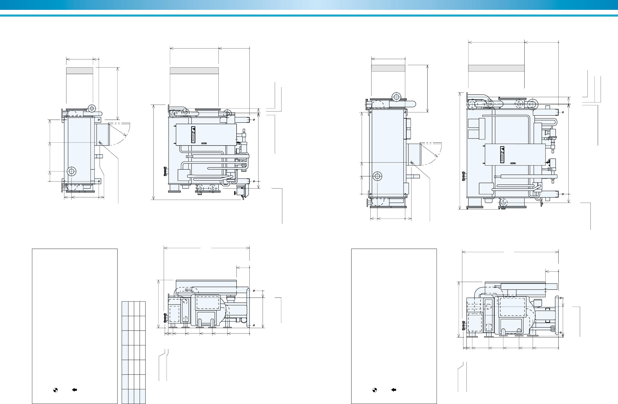
69
SUPER ABSORPTION
68
ENVIRONMENTALLY FRIENDLY TECHNOLOGY
Model A B C D L K
LE-01 1426 1566 1591 1687 2210 1900
LE-02 1426 1566 1591 1687 2210 1900
LE-03 1926 2066 2091 2187 2710 2400
Figure 50. LE-01 Thru LE-03
NOTES
1. Dimensions (L), (W), (H) are for the unit with rupture disk.
The dimensions are changed if additional parts are added.
2. indicates the position of anchor bolts.
3. All external water piping with welded JIS 10K flanges are to be provided by
the customer.
4. indicates the position of the power supply connection on control panel.
(diameter 33 mm)
5. Service space:
Longitudinal distance –1000 mm
Top –200 mm
Others –500 mm
6. Regarding fuel connection diameter and position, refer to specifications.
1110(W)
L
K
(Tube removal space either side)
1980
(H)
750
136
0
1840
715
0
300
0
860
0
160
800
630
0
20
R500
1958
1880
1770
1480
1150
860
510
0
HTW outlet
2-1/2 inch
HTW outlet
COW outlet
3 inch
COW inlet
3 inch
HTW inlet
2-1/2 inch
CHW outlet
2-1/2 inch
CHW inlet
2-1/2 inch
HTW outlet
CHW inlet / outlet
COW inlet / outlet
HTW inlet
165
0
900
230
Wire connection ø33 hole
0
Rupture Disk
4 inch
A
BCD
Figure 51. LE-11 Thru LE-12
NOTES
1. Dimensions (L), (W), (H) are for the unit with rupture disk.
The dimensions are changed if additional parts are added.
2. indicates the position of anchor bolts.
3. All external water piping with welded JIS 10K flanges are to be provided by
the customer.
4. indicates the position of the power supply connection on control panel.
(diameter 33 mm)
5. Service space:
Longitudinal distance –1000 mm
Top –200 mm
Others –500 mm
6. Regarding fuel connection diameter and position, refer to specifications.
1295(W) 2710(L)
2400
(Tube removal space either side)
2225
(H)
780
0
2085
785
0
300
0
910
882
0
200
800
640
0
145
R500
2203
2125
1995
1611
1275
911
595
0
HTW outlet
4 inch
HTW outlet
COW outlet
5 inch
COW inlet
5 inch
HTW inlet
4 inch
CHW outlet
3 inch
CHW inlet
3 inch
HTW outlet
CHW outlet
COW inlet / outlet HTW inlet
CTW inlet
200
2076
2096
2249
0
735
1896
415
Wire connection ø33 hole
0
Rupture Disk
4 inch
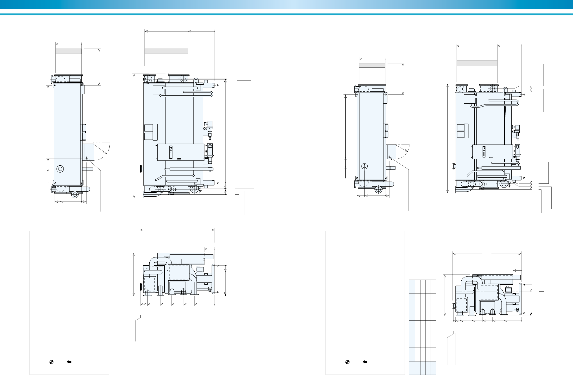
71
SUPER ABSORPTION
70
ENVIRONMENTALLY FRIENDLY TECHNOLOGY
Figure 52. LE-13 Thru LE-14
NOTES
1. Dimensions (L), (W), (H) are for the unit with rupture disk.
The dimensions are changed if additional parts are added.
2. indicates the position of anchor bolts.
3. All external water piping with welded JIS 10K flanges are to be provided by
the customer.
4. indicates the position of the power supply connection on control panel.
(diameter 33 mm)
5. Service space:
Longitudinal distance –1000 mm
Top –200 mm
Others –500 mm
6. Regarding fuel connection diameter and position, refer to specifications.
1295(W) 3720(L)
2225
(H)
780
0
2085
785
0
300
0
910
882
0
200
800
640
0
145
R500
2203
2125
1995
1611
1275
911
595
0
HTW outlet
4 inch
HTW outlet
COW outlet
5 inch
COW inlet
5 inch
HTW inlet
4 inch
CHW outlet
3 inch
CHW inlet
3 inch
CHW outlet CHW inlet
COW outlet
HTW outlet
HTW inlet
COW inlet
200
180
353
3096
3116
0
735
2916
415
Wire connection ø33 hole
0
Rupture Disk
4 inch
3400
(Tube removal space either side)
Model A B C D L K
LE-21 735 2916 3109 3128 3820 3400
LE-22 735 2916 3109 3128 3820 3400
LE-23 1185 3936 4129 4148 4850 4500
LE-24 1185 3936 4129 4148 4850 4500
Figure 53. LE-21 Thru LE-24
NOTES
1. Dimensions (L), (W), (H) are for the unit with rupture disk.
The dimensions are changed if additional parts are added.
2. indicates the position of anchor bolts.
3. All external water piping with welded JIS 10K flanges are to be provided by
the customer.
4. indicates the position of the power supply connection on control panel.
(diameter 33 mm)
5. Service space:
Longitudinal distance –1000 mm
Top –200 mm
Others –500 mm
6. Regarding fuel connection diameter and position, refer to specifications.
1455(W) L
2395
(H)
926
22
0
2255
835
0
300
0
1090
1065
0
251
1000
740
0
125
R500
2373
2295
2135
1724
1346
1006
605
0
HTW outlet
5 inch
HTW outlet
COW outlet
6 inch
COW inlet
6 inch
HTW inlet
5 inch
CHW outlet
5 inch
CHW inlet
5 inch
HTW outlet
CHW outlet
COW outlet
COW inlet
COW inlet
HTW inlet
195
212
403
0
415
Wire connection ø33 hole
0
Rupture Disk
4 inch
BA
CD
K
(Tube removal space either side)
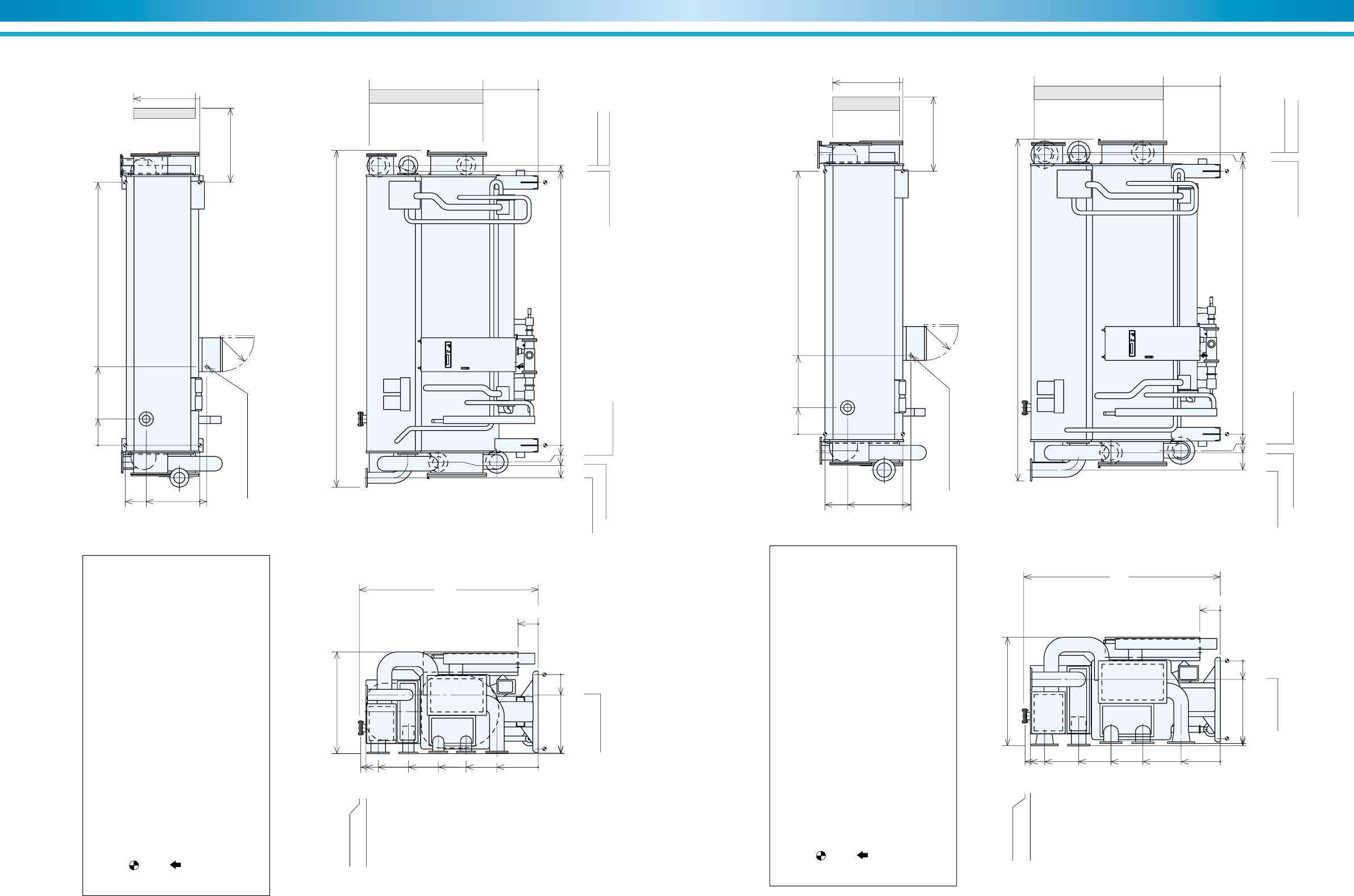
73
SUPER ABSORPTION
72
ENVIRONMENTALLY FRIENDLY TECHNOLOGY
Figure 54. LE-31 Thru LE-32
NOTES
1. Dimensions (L), (W), (H) are for the unit with rupture disk.
The dimensions are changed if additional parts are added.
2. indicates the position of anchor bolts.
3. All external water piping with welded JIS 10K flanges are to be provided by
the customer.
4. indicates the position of the power supply connection on control panel.
(diameter 33 mm)
5. Service space:
Longitudinal distance –1000 mm
Top –200 mm
Others –500 mm
6. Regarding fuel connection diameter and position, refer to specifications.
1515(W) 4980(L)
2645(H)
976
64
0
2500
815
0
300
0
1170
1156
0
250
1100
790
0
105
R500
2623
2545
2365
1918
1476
1066
611
0
HTW outlet
6 inch
HTW outlet
COW outlet
8 inch
COW inlet
8 inch
HTW inlet
6 inch
CHW outlet
6 inch
CHW inlet
6 inch
HTW outlet
CHW outlet COW outlet
COW inlet
HTW inlet
CHW inlet
244
4130
4136
250
479
0
390
1160
3886
Wire connection ø33 hole
0
Rupture Disk
4 inch
4500
(Tube removal space either side)
Figure 55. LE-41 Thru LE-42
NOTES
1. Dimensions (L), (W), (H) are for the unit with rupture disk.
The dimensions are changed if additional parts are added.
2. indicates the position of anchor bolts.
3. All external water piping with welded JIS 10K flanges are to be provided by
the customer.
4. indicates the position of the power supply connection on control panel.
(diameter 33 mm)
5. Service space:
Longitudinal distance –1000 mm
Top –200 mm
Others –500 mm
6. Regarding fuel connection diameter and position, refer to specifications.
1615(W) 5060(L)
2905
(H)
1036
50
0
2750
840
0
300
0
1255
1221
0
274
1150
815
0
120
R500
2883
2805
2595
2090
1613
1142
577
0
HTW outlet
8 inch
HTW outlet
COW outlet
10 inch
COW inlet
10 inch
HTW inlet
8 inch
CHW outlet
8 inch
CHW inlet
8 inch
HTW outlet
CHW outlet COW outlet
COW inlet HTW inlet
CHW inlet
244
4130
4162
276
530
0
390
1160
3886
Wire connection ø33 hole
0
Rupture Disk
4 inch
4500
(Tube removal space either side)
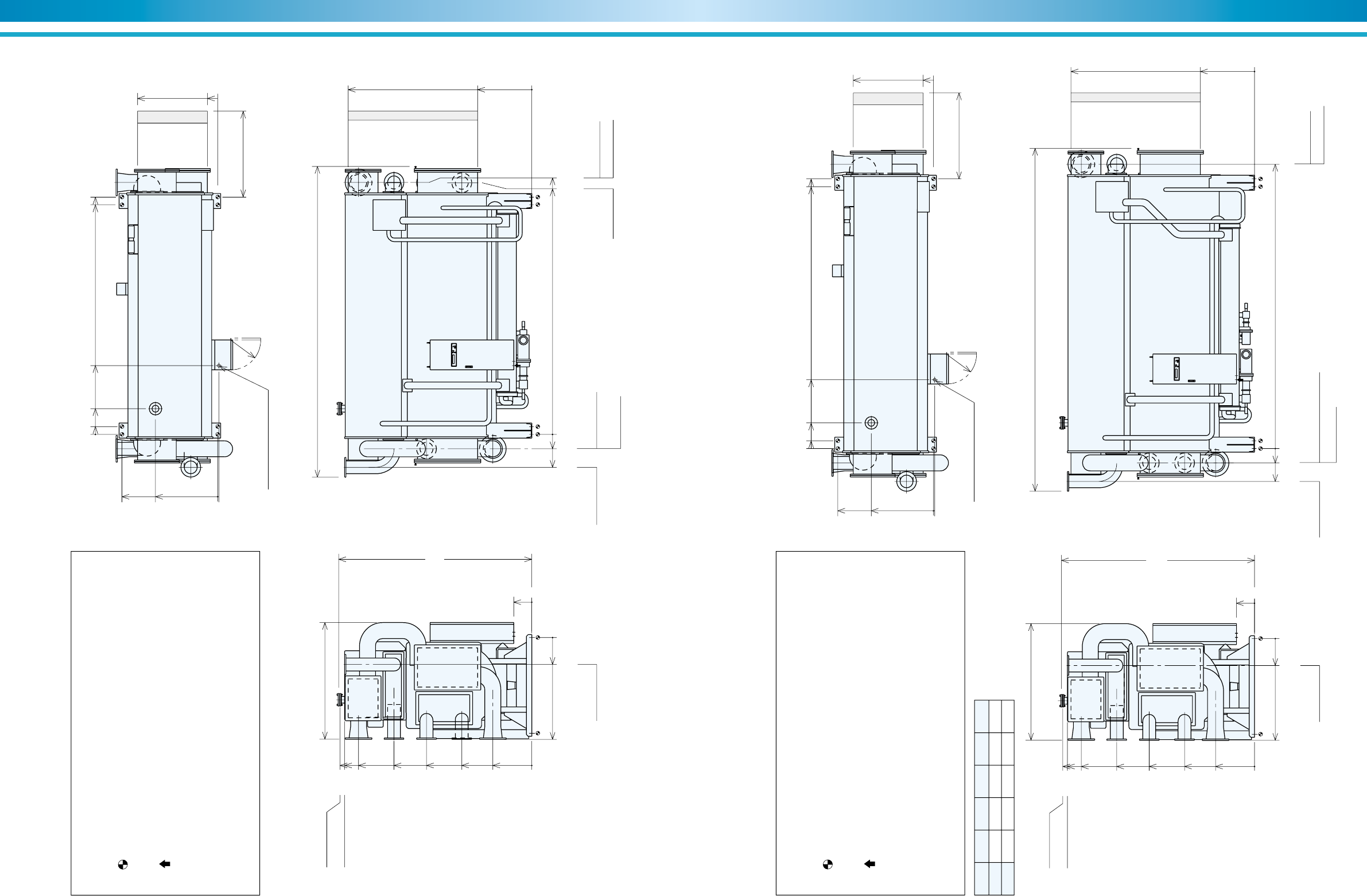
75
SUPER ABSORPTION
74
ENVIRONMENTALLY FRIENDLY TECHNOLOGY
Figure 56. LE-51
NOTES
1. Dimensions (L), (W), (H) are for the unit with rupture disk.
The dimensions are changed if additional parts are added.
2. indicates the position of anchor bolts.
3. All external water piping with welded JIS 10K flanges are to be provided by
the customer.
4. indicates the position of the power supply connection on control panel.
(diameter 33 mm)
5. Service space:
Longitudinal distance –1000 mm
Top –200 mm
Others –500 mm
6. Regarding fuel connection diameter and position, refer to specifications.
1950(W) 5200(L)
3230
(H)
1340
173
0
3075
905
0
300
0
1701
0
450
1600
1040
0
20
R500
3208
3130
2897
2304
1760
1170
651
0
HTW outlet
8 inch
HTW outlet
COW outlet
12 inch
COW inlet
12 inch
HTW inlet
8 inch
CHW outlet
8 inch
CHW inlet
8 inch
HTW outlet CHW outlet
COW outlet
COW inlet
HTW inlet
CHW inlet
4206
4211
240
550
0130
430
1150
3886
3966
Wire connection ø33 hole
0
Rupture Disk
4 inch
4600
(Tube removal space either side)
Model A B C L K
LE-52 4378 4508 4753 5740 5200
LE-53 4876 5006 5251 6240 5700
Figure 57. LE-52 Thru LE-53
NOTES
1. Dimensions (L), (W), (H) are for the unit with rupture disk.
The dimensions are changed if additional parts are added.
2. indicates the position of anchor bolts.
3. All external water piping with welded JIS 10K flanges are to be provided by
the customer.
4. indicates the position of the power supply connection on control panel.
(diameter 33 mm)
5. Service space:
Longitudinal distance –1000 mm
Top –200 mm
Others –500 mm
6. Regarding fuel connection diameter and position, refer to specifications.
1950(W)
L
3230
(H)
1340
173
0
3075
905
0
300
0
1701
0
450
1600
1040
0
20
R500
3208
3130
2897
2304
1760
1170
651
0
HTW outlet
8 inch
HTW outlet
COW outlet
12 inch
COW inlet
12 inch
HTW inlet
8 inch
CHW outlet
8 inch
CHW inlet
8 inch
HTW outlet CHW inlet / outlet
COW inlet
COW outlet
HTW inlet
240
550
0
1150
130
430
Wire connection ø33 hole
0
Rupture Disk
4 inch
AB
C
K
(Tube removal space either side)
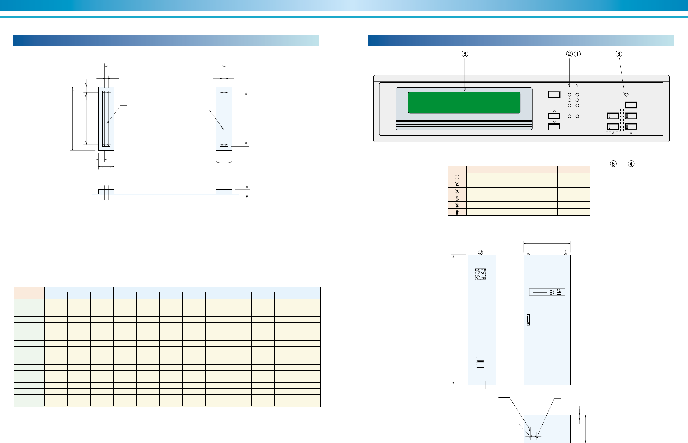
77
SUPER ABSORPTION
76
ENVIRONMENTALLY FRIENDLY TECHNOLOGY
Generator temp 69.9°C
MODE
STOP RUN
CHILLER
BUZZER STOP
STOP LOCAL
REMOTE
OPERATION
ALARM
REF PUMP
ABS PUMP
PURGE PUMP
SETTING
Name Lamp color
Running(Operation) indication lamp Red
Stop indication lamp Green
Alarm indication lamp Orange
Remote / Local select button with lamp Red
Mode select button with lamp Red
Data display LCD
symbol
Control panel (LE)
Hot water control valve
ø21 (LE-01 thru LE-12)
ø27 (LE-13 thru LE-24)
ø21 (LE-31 thru LE-53)
Power supply ø33
Remote control ø27
500
300 30
1400
Table 13. Indication lamp
Foundation dimensional data (LE)
Figure 58. LE-01 Thru 53
150
A
BB
D
C
E F
G
J
K
AA BB
Model
No.
Weight (kg) Dimensions (mm)
2,300 1,150 1,150 1,426 —113 226 800 100 1,000 125 900
2,400 1,200 1,200 1,426 —113 226 800 100 1,000 125 900
2,800 1,400 1,400 1,926 —113 226 800 100 1,000 125 900
3,900 1,950 1,950 1,896 —125 250 800 100 1,000 150 900
4,100 2,050 2,050 1,896 —125 250 800 100 1,000 150 900
5,100 2,550 2,550 2,916 —125 250 800 100 1,000 150 900
5,400 2,700 2,700 2,916 —125 250 800 100 1,000 150 900
6,500 3,250 3,250 2,916 —125 250 1,000 100 1,200 150 1,100
6,900 3,450 3,450 2,916 —125 250 1,000 100 1,200 150 1,100
8,000 4,000 4,000 3,936 —125 250 1,000 100 1,200 150 1,100
8,500 4,250 4,250 3,936 —125 250 1,000 100 1,200 150 1,100
10,300 5,150 5,150 3,886 —150 300 1,100 100 1,300 200 1,200
10,800 5,400 5,400 3,886 —150 300 1,100 100 1,300 200 1,200
12,500 6,250 6,250 3,886 —150 300 1,150 100 1,350 200 1,250
13,000 6,500 6,500 3,886 —150 300 1,150 100 1,350 200 1,250
17,700 8,850 8,850 3,966 130 110 350 1,600 100 1,800 250 1,700
19,200 9,600 9,600 4,508 130 110 350 1,600 100 1,800 250 1,700
20,600 10,300 10,300 5,006 130 110 350 1,600 100 1,800 250 1,700
LE-01
LE-02
LE-03
LE-11
LE-12
LE-13
LE-14
LE-21
LE-22
LE-23
LE-24
LE-31
LE-32
LE-41
LE-42
LE-51
LE-52
LE-53
Oper.
AA BB A B C D E F G J K
Table 12. Dimensional data
Figure 59. Control panel
NOTES :
1. The base of machine has ø50 hole for anchor bolt.
2. Anchor bolt should be fixed by shown detail drawing.
Washer should be welded with base.(Refer to Figure 21 page32)
3. There should be a drain ditch around the foundation.
4. The floor surface should be made as water proof for ease of
maintenance work.
5. Surface of foundation should be made flat.
6. Anchor bolts and nuts are supplied by customer.
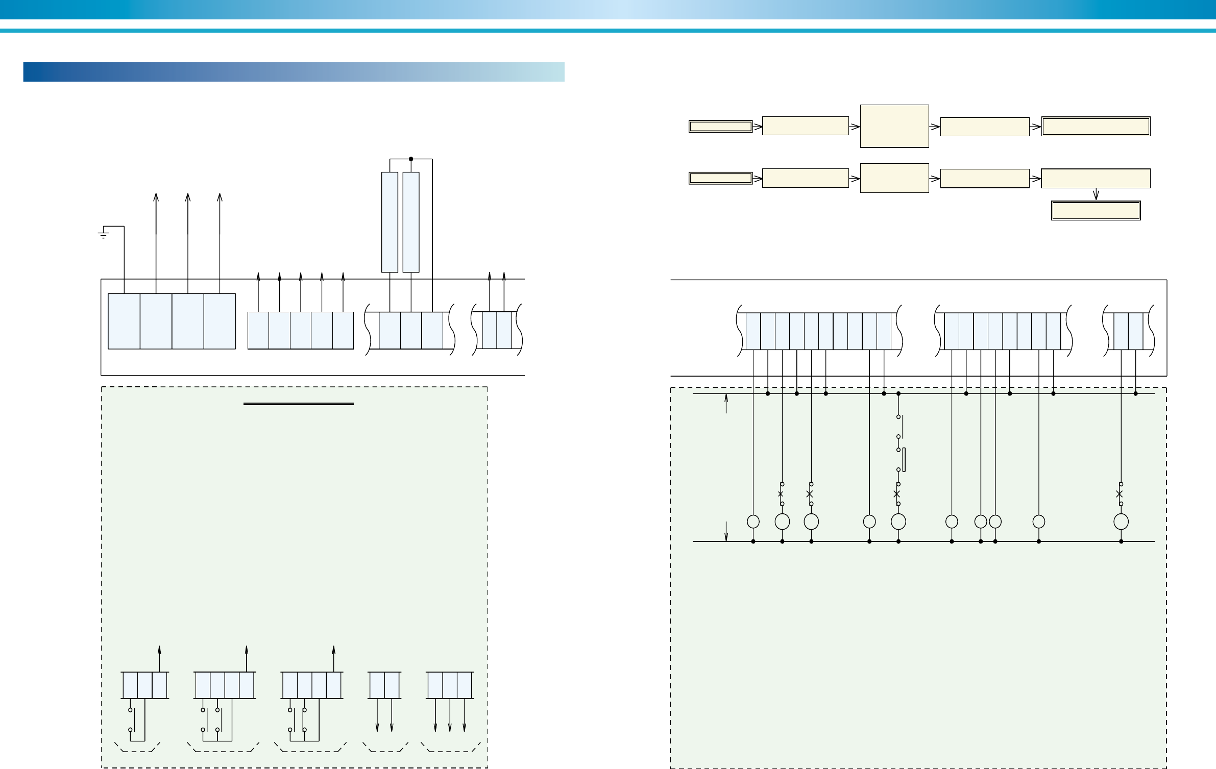
79
SUPER ABSORPTION
78
ENVIRONMENTALLY FRIENDLY TECHNOLOGY
Field wiring (LE)
Figure 60. Typical electrical field connection diagram - Hot water-fired (LE)
The unit can be operated by the following five type signal.
(1)Non-voltage normal open contact(A) for start & stop (DC24V 10mA).
:Wiring the terminal 330 and 333.
(2)Non-voltage normal open contact(A) for start (DC24V 10mA).
:Wiring the terminal 330 and 333.
Non-voltage normal open contact(A) for stop (DC24V 10mA).
:Wiring the terminal 331 and 333.
(3)Non-voltage normal open contact(A) for start (DC24V 10mA).
:Wiring the terminal 330 and 333.
Non-voltage normal close contact(B) for stop (DC24V 10mA).
:Wiring the terminal 331 and 333.
(4)Continuous signal of DC/AC 24V for start & stop.
:Wiring the terminal 330 and 332.(Those terminals are non-polarity.)
(5)Pulse signal of DC/AC 24V for start.
:Wiring the terminal 330 and 332.(Those terminals are non-polarity.)
Signal of DC/AC 24V for stop.
:Wiring the terminal 331 and 332.(Those terminals are non-polarity.)
Remote signal
Terminal strips in the control panel
Chilled water
pump interlock
To power source
3 Ph, 50/60Hz
380V, 400V, 415V, 440V
E
R0
S0
T0
(52CH)
171
Cooling water
pump interlock (52CO)
330
A
DC/AC 24VDC/AC 24V
(4)(1)
136
135
4Y
1
1
2
3
4
10
For emergency stop signal
(Those terminals are
connected by jumper)
Remove the jumper
before using
those terminals
333
332
171 171
330
A
(2)
4Y
1
331
333
332
4Y
2
AB
4Y
2
332
4Y
1
331
333
(3)
A
330
330
332
330
332
331
171
COM
84
85
For message signal
Note
1.Be sure to insert 23CO at the cooling water inlet side.
2.Be sure to wire the 52CH(interlock) between terminals 171 and 136.
3.Be sure to wire the 52CO(interlock) between terminals 171 and 135.
4.Be sure to wire the chilled water pump control relay between terminals 302 and 303.
5.Be sure to wire the cooling water pump control relay between terminals 304 and 305.
6.Be sure to wire the hot water pump control relay between terminals 345 and 346.
L :Indication lamp
51CH:Chilled water pump overcurrent relay
51CO:Cooling water pump overcurrent relay
51CT :Cooling tower fan overcurrent relay
51H :Hot water pump overcurrent relay
23CO:Cooling tower fan thermostat
Symbols
Terminal strips in the control panel
LL
Max. voltage and
Max. current
:AC 250V,0.1A
Stop
indication
Operation
indication
Answer back
indication
52
CT 52
H
Chilled
water pump
52
CH
51
CH 51
CT
Cooling tower
fan
52
CO
23
CO
51
CO
52
CO
Cooling water
pump
Start/Stop sequence of auxiliary equipments
Start
Start signal Machine operates
Chilled water pump operates
Cooling water pump
operates and then
cooling tower fan
operates
Stop
Stop signal Diluted operation start Chiller stops entirely
Cooling water pump
stops and cooling
tower fan stops
L
Chilled water pump stops
300
301
302
303
304
305
306
307
308
309
320
321
322
323
324
325
326
327
345
346
L
Remote signal
indication
L
Alarm
indication
L
Buzzer signal
indication
51
H
Hot water
pump
Operate air conditioners
Stop air conditioners
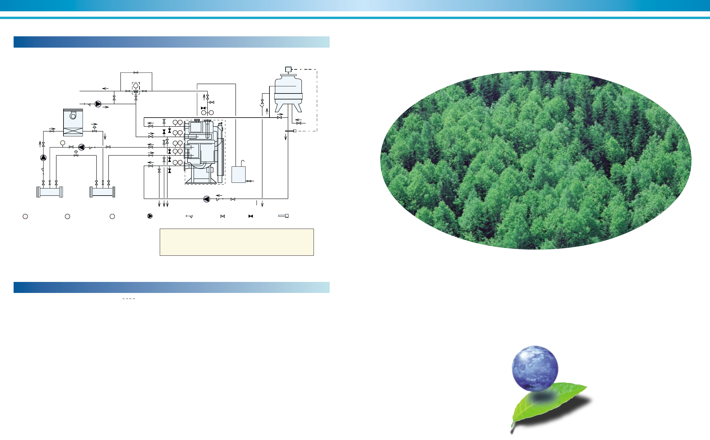
81
SUPER ABSORPTION
80
ENVIRONMENTALLY FRIENDLY TECHNOLOGY
1. Work outside the area surrounded by this line shall be under-
taken at the expense of the owner.
2. Refer to the Dimensions diagrams and specification tables for pipe
connections and diameters.
3. Determine the locations of the chilled, cooling and hot water pump in
due consideration of the pump’s hydrostatic head.
As standard condition, the machine should not be subject to a
pressure larger than 8 kg/cm2G. at any water headers.
4. Concerning the temperature control of cooling water, refer to the
section of ”control method of cooling water temperature”.
5. Provide a thermometer and a pressure gauge at the outlet and inlet
of cooling water temperature.
General remarks on piping work
6. Provide an air vent valve in each of the chilled, cooling and hot water
lines at a point higher than the header for chilled, cooling and hot
waters.
7. Lay pipes from the cover of the evaporator, absorber and generator
to drain ditch.
8. Provide a bleeder in the cooling water line for control of water quality.
9. All external water piping are to be provided with JIS 10k welding flanges
by the customer.
10.Be sure to design the location of cooling tower to prevent
contamination of cooling water by exhaust gas from flues.
Supply
Header Return
Header
Secondary
Chilled
Water pump Bypass valve
Primary
Chilled water pump
Air
Conditioner
Hot water
Pump
Hot water
3 way valve
Cooling water pump
Cooling
tower
Make up
water
To drain
To drain
F
CC
T
T
T
T
T
P
P
T
P
P
P
P
Air vent
In order to prevent freezing up of chilled water when the chilled water
gets a stop signal, continue the operation of the primary chilled water
pump and secondary chilled water pump and air conditioner during
dilution cycle operation of the chillers.
T
: Thermometer
P
: Pressure gauge
F
: Flow meter : Water pump : Strainer : Valve : Valve : Thermostat
Tank
above
1m
3
Utility
1.Unit selection tables
2.Pressure drop curves
3.Installation and application data
4.Management of cooling water quality
5.Installation examples
Typical piping diagram-laying (LE)
Figure 61. Typical piping diagram
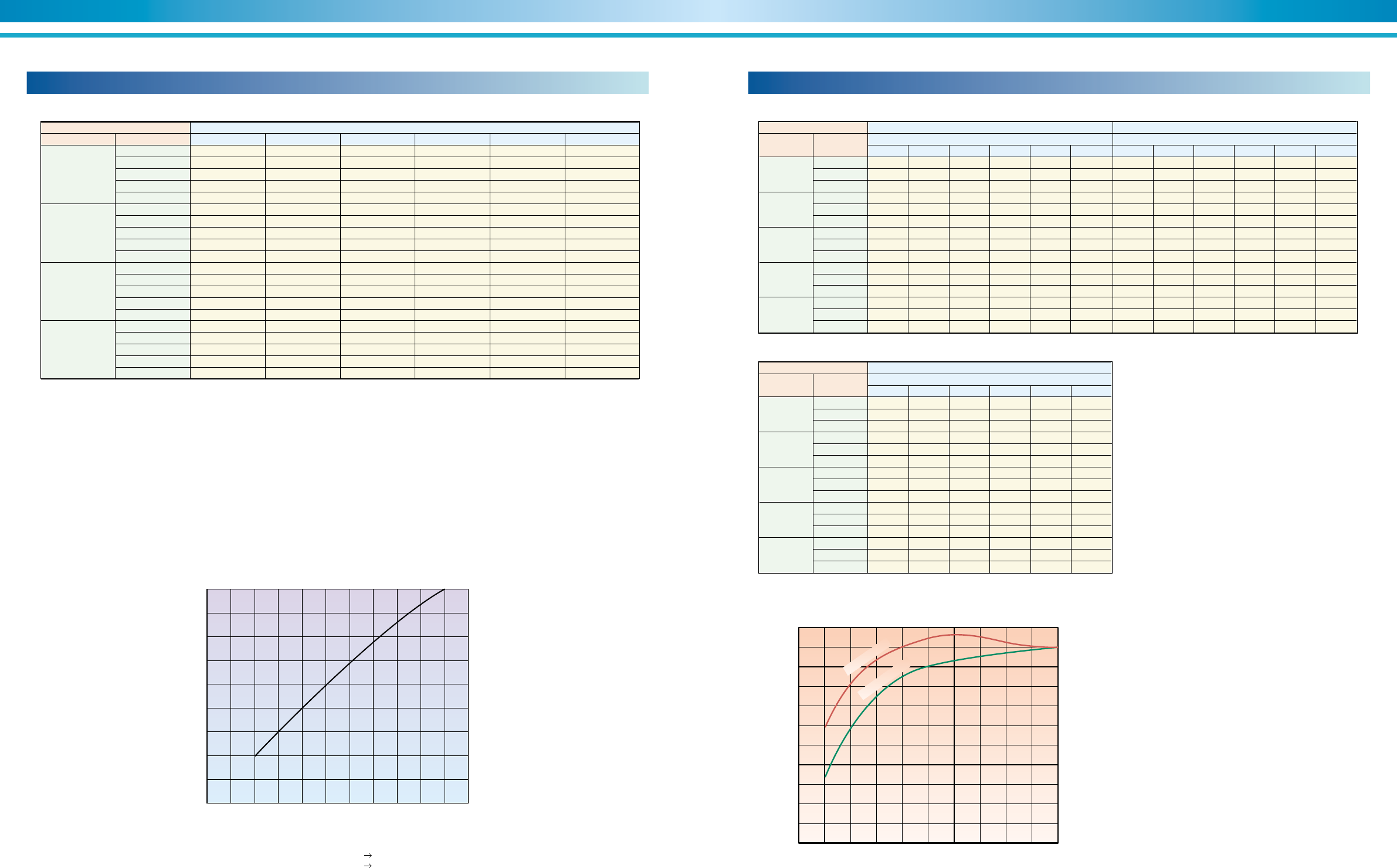
83
SUPER ABSORPTION
82
ENVIRONMENTALLY FRIENDLY TECHNOLOGY
Capacity ratings (DE and NE)
Chilled water temperature Cooling water inlet temperature (°C)
Outlet temp.
5.0
6.0
7.0
8.0
Inlet temp. 28 29 30 31 32 33
8.0
9.0
10.0
11.0
12.0
8.0
9.0
10.0
11.0
12.0
8.0
9.0
10.0
11.0
12.0
8.0
9.0
10.0
11.0
12.0
0.826 0.803 0.780 0.753 0.716 0.634
0.883 0.859 0.834 0.805 0.766 0.678
0.922 0.898 0.871 0.841 0.800 0.708
0.940 0.915 0.888 0.857 0.815 0.721
0.957 0.932 0.904 0.873 0.830 0.735
0.929 0.904 0.877 0.847 0.806 0.713
0.993 0.966 0.938 0.905 0.861 0.762
1.038 1.010 0.980 0.946 0.900 0.797
1.050 1.029 0.999 0.964 0.917 0.812
1.050 1.048 1.017 0.982 0.934 0.827
1.032 1.004 0.975 0.941 0.895 0.792
1.050 1.050 1.042 1.006 0.957 0.847
1.050 1.050 1.050 1.050 1.000 0.885
1.050 1.050 1.050 1.050 1.019 0.902
1.050 1.050 1.050 1.050 1.038 0.919
1.050 1.046 1.016 0.980 0.933 0.825
1.050 1.050 1.050 1.048 0.997 0.883
1.050 1.050 1.050 1.050 1.042 0.922
1.050 1.050 1.050 1.050 1.050 0.940
1.050 1.050 1.050 1.050 1.050 0.957
COW inlet CHW outlet
6.0
7.0
8.0
6.0
7.0
8.0
6.0
7.0
8.0
6.0
7.0
8.0
6.0
7.0
8.0
28.0
29.0
30.0
31.0
32.0
COW inlet CHW outlet
6.0
7.0
8.0
6.0
7.0
8.0
6.0
7.0
8.0
6.0
7.0
8.0
6.0
7.0
8.0
28.0
29.0
30.0
31.0
32.0
CHW ∆T = 4 deg CHW ∆T = 5 deg
Hot water outlet (°C) Hot water outlet (°C)
CHW ∆T = 6 deg
80.0 81.0 82.0 83.0 84.0 85.0
Hot water outlet (°C)
1.084 1.131 1.177 1.223 1.268 1.300
1.151 1.197 1.243 1.288 1.300 1.300
1.217 1.263 1.300 1.300 1.300 1.300
0.970 1.017 1.065 1.111 1.158 1.204
1.037 1.084 1.131 1.177 1.223 1.268
1.104 1.151 1.197 1.242 1.288 1.300
0.853 0.902 0.950 0.998 1.046 1.092
0.921 0.970 1.017 1.064 1.111 1.158
0.989 1.037 1.084 1.131 1.177 1.223
0.733 0.784 0.834 0.883 0.932 0.980
0.803 0.853 0.902 0.950 0.998 1.045
0.872 0.921 0.970 1.017 1.064 1.111
***
0.661 0.714 0.765 0.815 0.865
0.680 0.733 0.784 0.834 0.883 0.932
0.752 0.803 0.853 0.902 0.950 0.998
80.0 81.0 82.0 83.0 84.0 85.0
1.046 1.092 1.137 1.183 1.228 1.272
1.111 1.156 1.202 1.247 1.291 1.300
1.176 1.221 1.266 1.300 1.300 1.300
0.934 0.980 1.027 1.073 1.119 1.164
0.999 1.046 1.092 1.137 1.182 1.227
1.065 1.111 1.156 1.201 1.246 1.291
0.820 0.868 0.915 0.962 1.008 1.055
0.886 0.934 0.980 1.027 1.073 1.118
0.953 0.999 1.046 1.091 1.137 1.182
0.703 0.753 0.802 0.850 0.897 0.944
0.771 0.820 0.868 0.915 0.962 1.008
0.838 0.886 0.934 0.980 1.027 1.073
0.583 0.635 0.685 0.735 0.784 0.832
0.653 0.703 0.753 0.802 0.850 0.897
0.722 0.771 0.820 0.868 0.915 0.962
80.0 81.0 82.0 83.0 84.0 85.0
1.066 1.112 1.158 1.204 1.249 1.294
1.132 1.178 1.223 1.268 1.300 1.300
1.198 1.243 1.288 1.300 1.300 1.300
0.953 1.000 1.047 1.093 1.139 1.185
1.019 1.066 1.112 1.158 1.204 1.249
1.085 1.132 1.177 1.223 1.268 1.300
0.837 0.886 0.934 0.981 1.028 1.074
0.905 0.953 1.000 1.047 1.093 1.139
0.972 1.019 1.066 1.112 1.158 1.203
0.719 0.769 0.819 0.867 0.915 0.963
0.788 0.837 0.886 0.934 0.981 1.028
0.856 0.905 0.953 1.000 1.047 1.093
0.597 0.649 0.701 0.751 0.801 0.849
0.668 0.719 0.770 0.819 0.867 0.915
0.738 0.788 0.838 0.886 0.934 0.981
100
90
80
70
60
45678
Supply steam pressure(Kg / cm2G)
Selection condition
1) Chilled water 12°C 7°C
2) Cooling water 32°C 37.5°C
Cooling capacity
(%)
XXXX Note :
1) Cooling water temperature difference : 5.5°C constant
2) The table is used only for the purpose of presuming the capacity factor.
3) In DE model, the proper flow rate of hot water is required in case of heating mode.
It requires proper consumption of hot water for required cooling capacity.
4) Please contact your SANYO representative, if your request is not indicated in the table.
Table 14. Capacity factor (DE and NE)
Capacity ratings (LE)
Table 15. Capacity factor (LE)
Note :
1) Cooling water temperrature difference : 6°C constant
Hot water temperature difference : 5°C constant
2) The table is used only for the purpose of presumpting
the capacity factor.
3) It requires proper consumption of hot water for required
cooling capacity.
4) Please contact your SANYO representative, if your
request is not indicated in the table.
5) ” *** ” mark means out of operation condition.
Graph 12. Partial load characteristics
0 102030405060708090100
0
10
20
30
40
70
60
50
110
100
90
80
Load (%)
COP (%)
w/ inverter
w/o inverter
Adoption of the controlling circulation amount of the solution
In order to have a stable and effective operation under the wide range of
hot water temperature given, absorbent pump driven by an inverter con-
trols the optimal operation. This control is that hot water is effectively
utilized to regenerate the refrigerant instead of heating up the solution
not attributed to the cooling capacity at the partial load.
Features;
1. To shorten the start-up period in time.
2. To prevent the excessive heat rejection to the cooling water system.
Even if the heating amount of heat source becomes less, the unit can
operate without fail by means of the procedure that the input is almost
rejected to cooling water.
3.To improve COP at the partial load due to less input.
Graph 11. Cooling capacity and steam pressure
(steam-fired chillers)
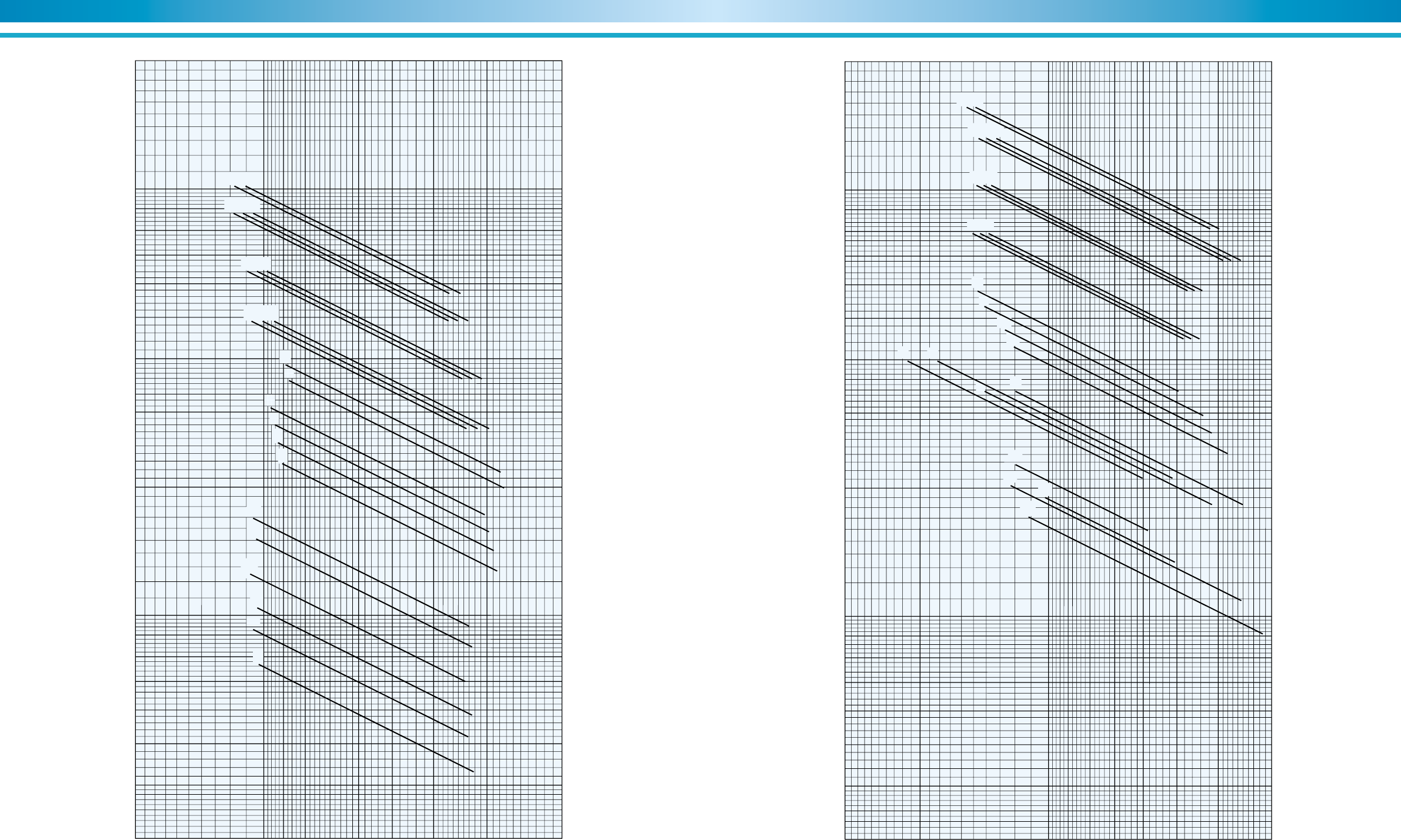
85
SUPER ABSORPTION
84
ENVIRONMENTALLY FRIENDLY TECHNOLOGY
Pressure drop (kPa)
Flow rate (m
3
/h)
Graph 13.
Chilled water pressure drop curve (DE and NE)
900800700
600
500
400300 2000
200
40
1009080
20
30
100
90
80
7060504030 200
70
60
50
1000
11 12 13 14 21 22
23 24 31 32
41 42
53
52
51
63
62
61
73
72
71
82
81
Graph 14.
Cooling water pressure drop curve (DE and NE)
900800700
600500400300 2000
200
40
1009080
30
100
90
80
7060504030 200
70
60
50
1000
11
12
13
14
21
22
23
24
31 32
41 42 53
52
51
63
62
61 71
72
73 81
82
300
Pressure drop (kPa)
Flow rate (m
3
/h)
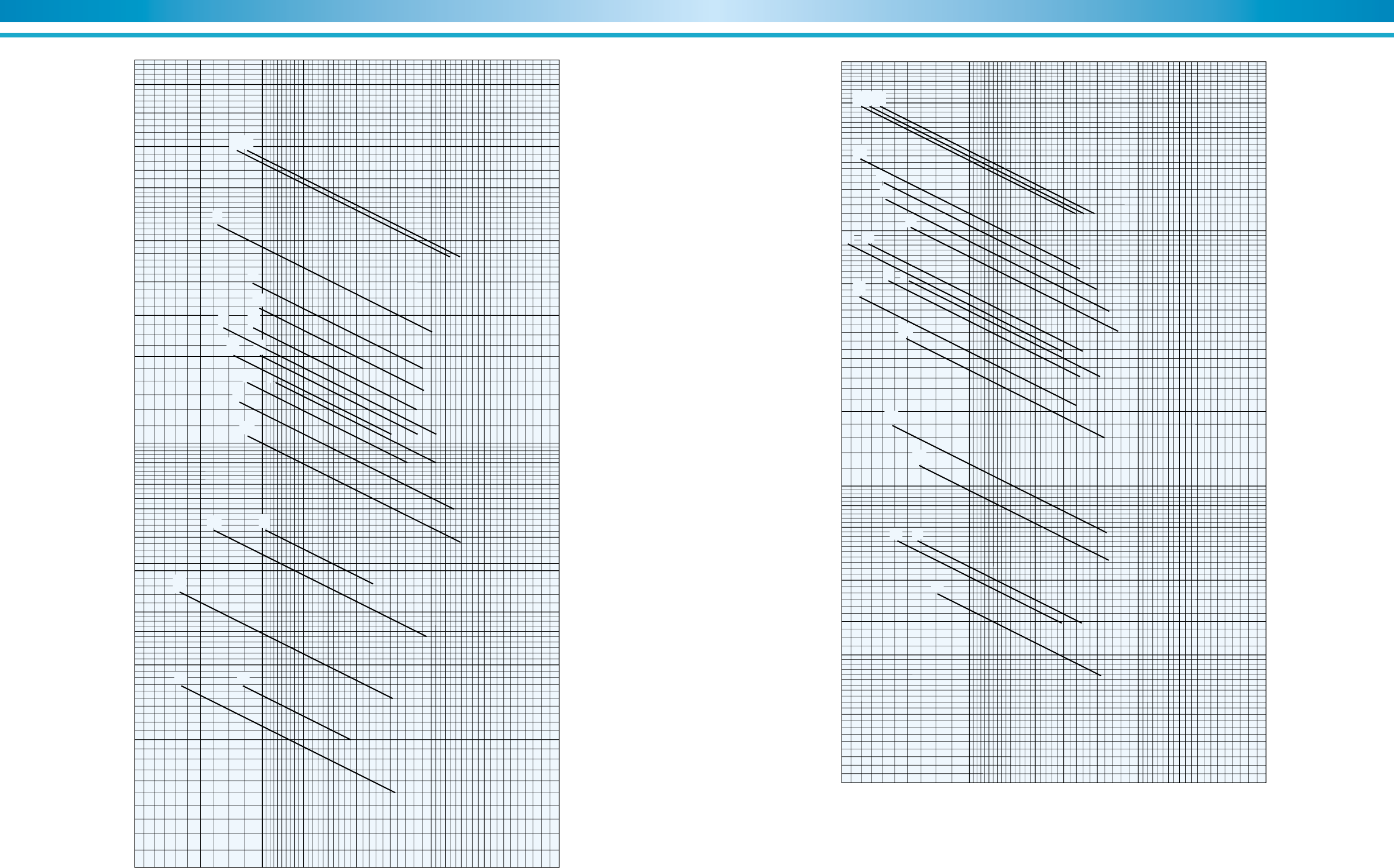
87
SUPER ABSORPTION
86
ENVIRONMENTALLY FRIENDLY TECHNOLOGY
800700
60050040030010090807060504030 2002010
01
02
03
11
12
13 14
21
22
24
31
32 41 42
51
52
53
23
Graph 15.
Chilled water pressure drop curve (LE)
200
40
30
20
100
90
80
70
60
50
Pressure drop (kPa)
Flow rate (m
3
/h)
800700
60050040030010090807060504030 20020 900 1000
01
02
03
11
12
13
14
21
22
23
24
31
32 41
42
51
52
53
Graph 16.
Cooling water pressure drop curve (LE)
200
40
30
20
100
90
80
70
60
50
Pressure drop (kPa)
Flow rate (m
3
/h)
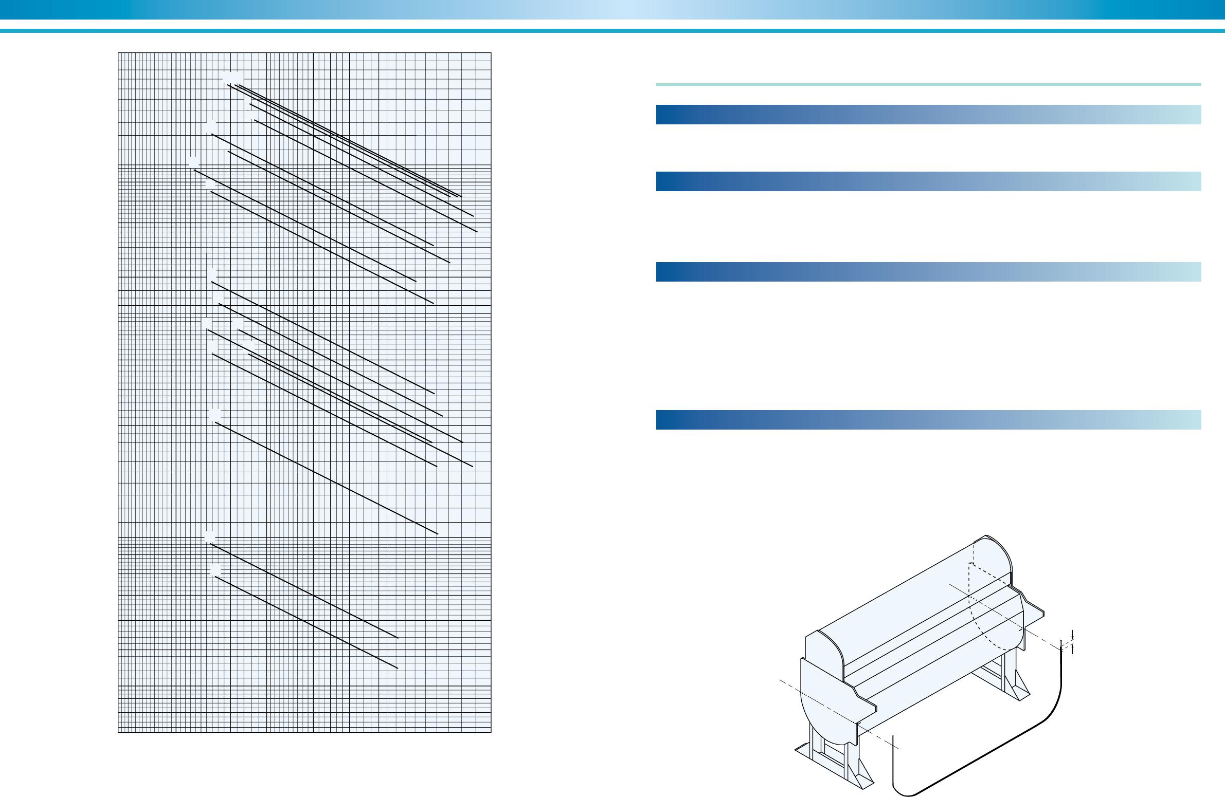
89
SUPER ABSORPTION
88
ENVIRONMENTALLY FRIENDLY TECHNOLOGY
1. In order to prevent freeze-up of chilled water during unit shutdown,
the chilled water pump(s) and air handler must be run for 15 minutes
after the burner is shut off. This will allow time for the automatic dilu-
tion cycle to be completed.
2. The standard unit must not be subjected to water pressures in excess
of 981 kPa (10 kg/cm2G).
3. An expansion tank should be provided in the chilled/hot water line.
4. Thermometers and pressure gauges should be field-installed at the
inlet and outlet of the chilled/hot water line, and the cooling water
line.
5. During heating operation, the cooling water circuit should not be in
operation and should be blown down.
6. All external piping connections are provided with JIS 10K flanges un-
less noted.
7. A drain line must be installed from the smoke chamber drain to a floor
drain.
8. See Figure 32 (DE), Figure 48 (NE), Figure 61 (LE) for typical sys-
tem piping arrangement.
Field piping instruction
908070
60504030 200
109876543 20 100
01 02 03
11
12
13 21
14 22 23
24
31
32
41 42 51
52
53
Graph 17.
Hot water pressure drop curve (LE)
40
30
10
20
100
90
80
70
60
50
Pressure drop (kPa)
Flow rate (m
3
/h)
Installation and application data
Location and space requirements
The unit is designed for indoor application and must be located in a space
where the surrounding temperature of equipment is between 5°C and
45°C, and at no more than 90% relative humidity. Clearance must be
provided on either end to facilitate tube cleaning, or removal and clear-
ance on all other sides of the unit for general unit maintenance. See the
dimensional data tables for clearance requirements.
Water piping should be arranged so that the circulating pumps discharge
directly into the vessels. The water piping should be insulated to reduce
heat gain and to prevent condensation. Air vents should be located at all
high points in the water piping system, and drains should be located at all
low points to facilitate complete system drainage. To reduce vibration
and noise transmission, vibration absorbers should be provided. Shutoff
valves should be provided to allow unit isolation during maintenance.
Chilled water flow switch is provided on the unit and is preset to open at
approximately 50% of specified flow rate.
Water piping
D
B
C
AEvaporator side
Absorber side
Strict leveling tolerances must be adhered to for trouble-free operation.
SANYO units are furnished with four leveling reference points, one on
each corner of the lower shell or tube sheet. Each reference point is
designated by three punch marks. A convenient method to check level-
ing tolerances is to fill a clear vinyl hose with water and measure the
difference in the water level at the two points. The tolerance that must be
maintained from end-to-end and side-to side is 1mm (1/25'') of difference
for each 1m length between points. It is not necessary to check levels
diagonally. When the unit does not meet this requirement, the unit must
be shimmed in order to meet leveling tolerances.
Leveling requirements
Figure 62. Leveling the chiller
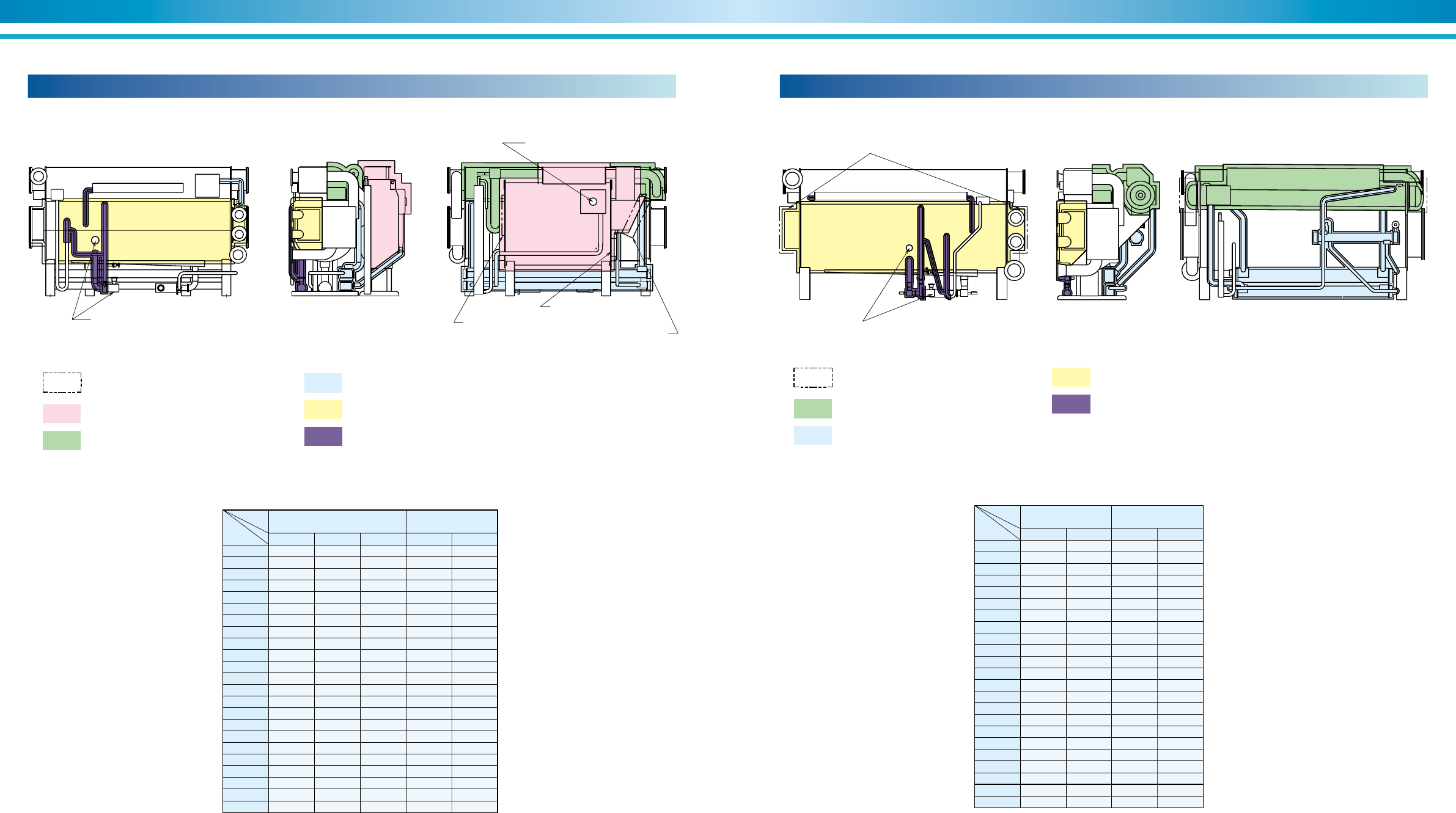
91
SUPER ABSORPTION
90
ENVIRONMENTALLY FRIENDLY TECHNOLOGY
100mm thick insulation for hot surface
75mm thick insulation for hot surface
Don't insulate the motor,
refrigerant pump and sight glass.
Don't insulate sight glass.
Evaporator cover and chamber cover are
removable in construction
*2 Chamber cover *2 Chamber cover
50mm thick insulation
for hot surface
50mm thick insulation for hot surface
30mm thick insulation for cold surface
30mm thick insulation for cold surface
Model 100mm 75mm 30mm 50mm 30mm
DE-11 5.8 2.2 2.9 4.0 0.4
DE-12 6.2 2.2 3.0 4.0 0.4
DE-13 7.8 3.2 4.2 5.5 0.4
DE-14 8.0 3.2 4.3 5.5 0.4
DE-21 10.1 3.8 4.9 6.1 0.5
DE-22 10.4 3.8 5.0 6.1 0.5
DE-23 11.8 4.8 5.5 7.6 0.5
DE-24 12.5 4.8 5.6 7.6 0.5
DE-31 14.5 5.5 6.2 8.5 0.7
DE-32 15.2 5.5 6.4 8.5 0.7
DE-41 17.5 5.7 6.8 9.9 0.7
DE-42 18.1 5.7 7.0 9.9 0.7
DE-51 19.6 5.4 7.6 13.8 1.1
DE-52 20.7 5.9 7.9 15.0 1.1
DE-53 21.7 6.2 8.2 16.1 1.1
DE-61 25.4 7.2 9.7 17.5 1.2
DE-62 27.2 7.7 10.1 18.7 1.2
DE-63 28.9 8.2 10.5 20.0 1.2
DE-71 35.4 10.4 12.1 10.9 1.4
DE-72 37.4 10.7 12.4 11.4 1.4
DE-73 39.4 11.0 12.7 11.8 1.4
DE-81 42.5 11.0 13.0 13.1 1.5
DE-82 44.0 11.3 13.5 13.6 1.5
Hot surface
insulation(m2)Cold surface
insulation(m2)
Insulation (DE)
Figure 63. Insulation of DE
Evaporator cover
Don't insulate the motor,
refrigerant pump and sight glass.
75mm thick insulation for hot surface
50mm thick insulation for hot surface
Evaporator cover and chamber cover are
removable in construction 30mm thick insulation for cold surface
30mm thick insulation for cold surface
Model 75mm 30mm 50mm 30mm
NE-11 5.2 3.5 4.0 0.4
NE-12 5.2 3.6 4.0 0.4
NE-13 7.3 4.8 5.5 0.4
NE-14 7.3 4.9 5.5 0.4
NE-21 8.3 5.7 6.1 0.5
NE-22 8.3 5.8 6.1 0.5
NE-23 10.5 6.3 7.6 0.5
NE-24 10.5 6.4 7.6 0.5
NE-31 11.6 7.1 8.5 0.7
NE-32 11.6 7.3 8.5 0.7
NE-41 13.0 7.7 9.9 0.7
NE-42 13.0 7.9 9.9 0.7
NE-51 13.8 8.9 13.8 1.1
NE-52 15.4 9.2 15.0 1.1
NE-53 17.0 9.5 16.1 1.1
NE-61 18.4 11.0 17.5 1.2
NE-62 20.2 11.4 18.7 1.2
NE-63 22.0 11.8 20.0 1.2
NE-71 20.9 13.7 10.9 1.4
NE-72 22.6 14.0 11.4 1.4
NE-73 24.6 14.3 11.8 1.4
NE-81 24.4 14.6 13.1 1.5
NE-82 26.4 15.1 13.6 1.5
Hot surface
insulation(m
2
)Cold surface
insulation(m
2
)
Figure 64. Insulation of NE
Insulation (NE)
Table 16. Insulation data Table 17. Insulation data
Notice :
1) Material : Glass wool or rock wool (non-combustible type)
2) The total area includes the area of pipes in the chiller/heaters.
3) The machine is coated with rust preventive paint before shipment,
but is not provided with finish paint.
Notice :
1) Material : Glass wool or rock wool (non-combustible type)
2) The total area includes the area of pipes in the chiller.
3) The machine is coated with rust preventive paint before shipment,
but is not provided with finish paint.
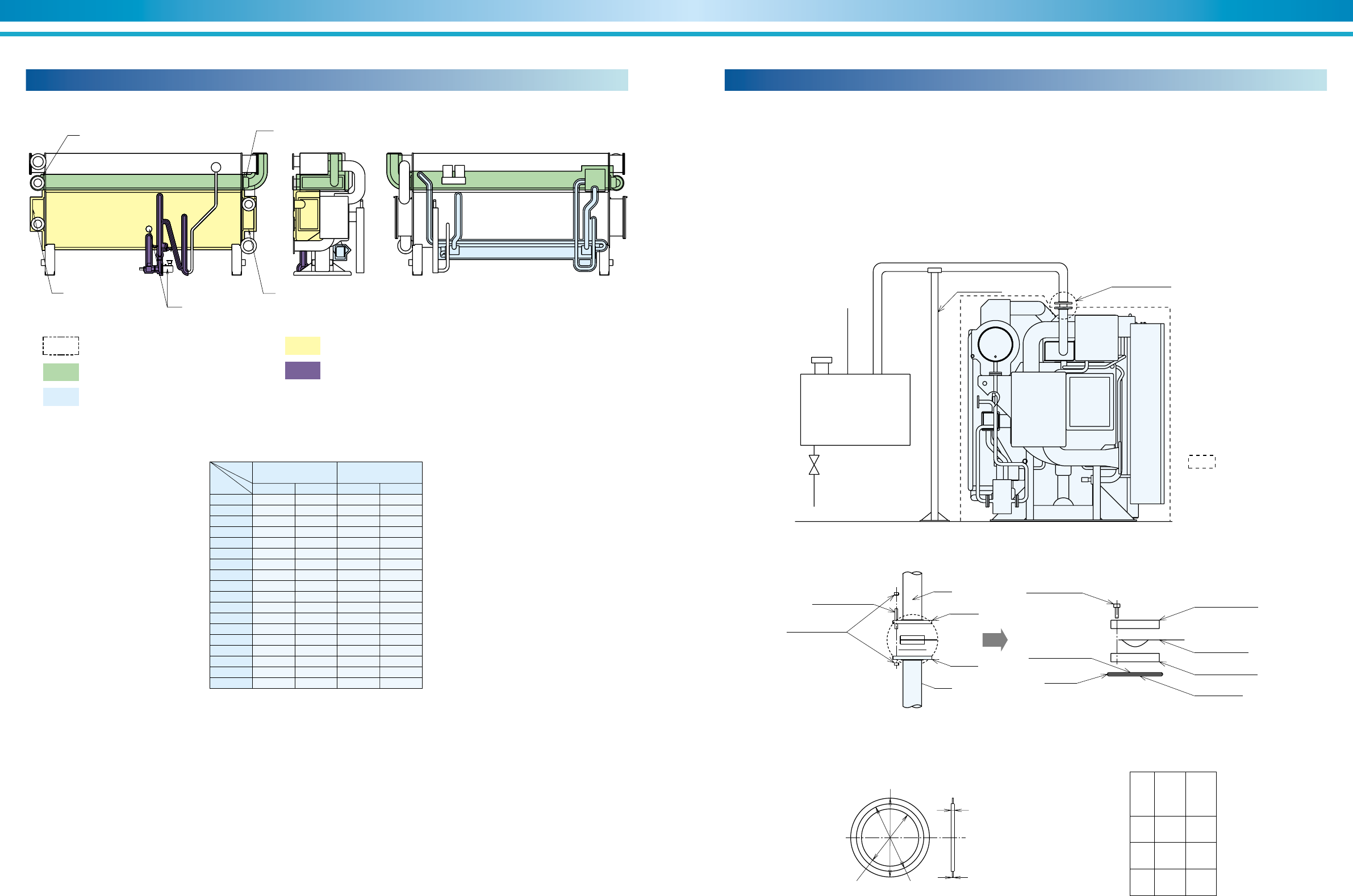
93
SUPER ABSORPTION
92
ENVIRONMENTALLY FRIENDLY TECHNOLOGY
Evaporator cover Evaporator cover
Generator cover Generator cover
Don't insulate the motor,
refrigerant pump and sight glass.
75mm thick insulation for hot surface
50mm thick insulation for hot surface
Evaporator cover and chamber cover are
removable in construction 30mm thick insulation for cold surface
30mm thick insulation for cold surface
Model 75mm 30mm 50mm 30mm
LE-01 2.3 1.4 3.3 0.2
LE-02 2.3 1.4 3.3 0.2
LE-03 2.7 1.6 3.9 0.3
LE-11 2.8 1.6 4.0 0.3
LE-12 2.8 1.8 4.0 0.3
LE-13 3.8 1.9 5.5 0.3
LE-14 3.8 2.2 5.5 0.3
LE-21 4.0 2.5 6.1 0.4
LE-22 4.0 2.5 6.1 0.4
LE-23 5.2 3.1 7.6 0.5
LE-24 5.2 3.3 7.6 0.5
LE-31 6.0 3.5 8.5 0.5
LE-32 6.0 3.6 8.5 0.5
LE-41 6.6 3.7 9.9 0.5
LE-42 6.6 3.9 9.9 0.5
LE-51 7.6 4.8 13.8 0.7
LE-52 8.4 5.1 15.0 0.7
LE-53 9.2 5.3 16.1 0.7
Hot surface
insulation(m
2
)Cold surface
insulation(m
2
)
Notice :
1) Material : Glass wool or rock wool (non-combustible type)
2) The total area includes the area of pipes in the chiller.
3) The machine is coated with rust preventive paint before shipment,
but is not provided with finish paint.
Figure 65. Insulation of LE
Insulation (LE)
In some instances local codes may dictate the use of a rupture disk to
prevent damage to the chiller in the event of overpressurization of the
high and low temperature generators. SANYO units are provided with a
flange for mounting a rupture disk.
At this flange connection, a rupture disk may be installed and connected
to a field-provided overflow tank per Figure 66.
It is the responsibility of the installing contractor to install the rupture disk
on the units and overflow tank (if required) prior to initial chiller startup.
Rupture disk mounting
Rupture disk mounting instructions are as follows:
1. Prior to installing or replacing the rupture disk, insure that a slight
positive pressure is maintained in the chiller with nitrogen gas.
2. Apply Teflon paste to both sides of gasket.
3. Align gasket as shown in Figure 68.
4. Assemble flanges and torque per specifications shown in the manual
of rupture disk.
5. Conduct leak test using nitrogen gas at 49 kPa (0.5 kg/cm2G) after
installation of rupture disk.
6. Periodic maintenance should include tightening the rupture disk with
a torque wrench.
4.5
3.2
4 inch
• Material : T/#9090-OR
disk
6 inch
disk
A
B
C
(mm)
(mm)
(mm)
174.8
149.4
127.6
222.3
209.6
182.6
C B
A
Pipe
Pipe
Flange
Flange
High tension nut
High tension bolt
To tank
From chiller
Teflon paste
Safety head
: Scope of supply by SANYO
Rupture disk
Safety head
Teflon paste
Gasket
Cap screw
Above 35 QFT
Discharge piping
Rupture disk
Vent piping
Drain
Tank
Support
Figure 66. Piping of rupture disk
Figure 67. Fixing methed of rupture disk
Figure 68. Gasket
Table 18. Insulation data
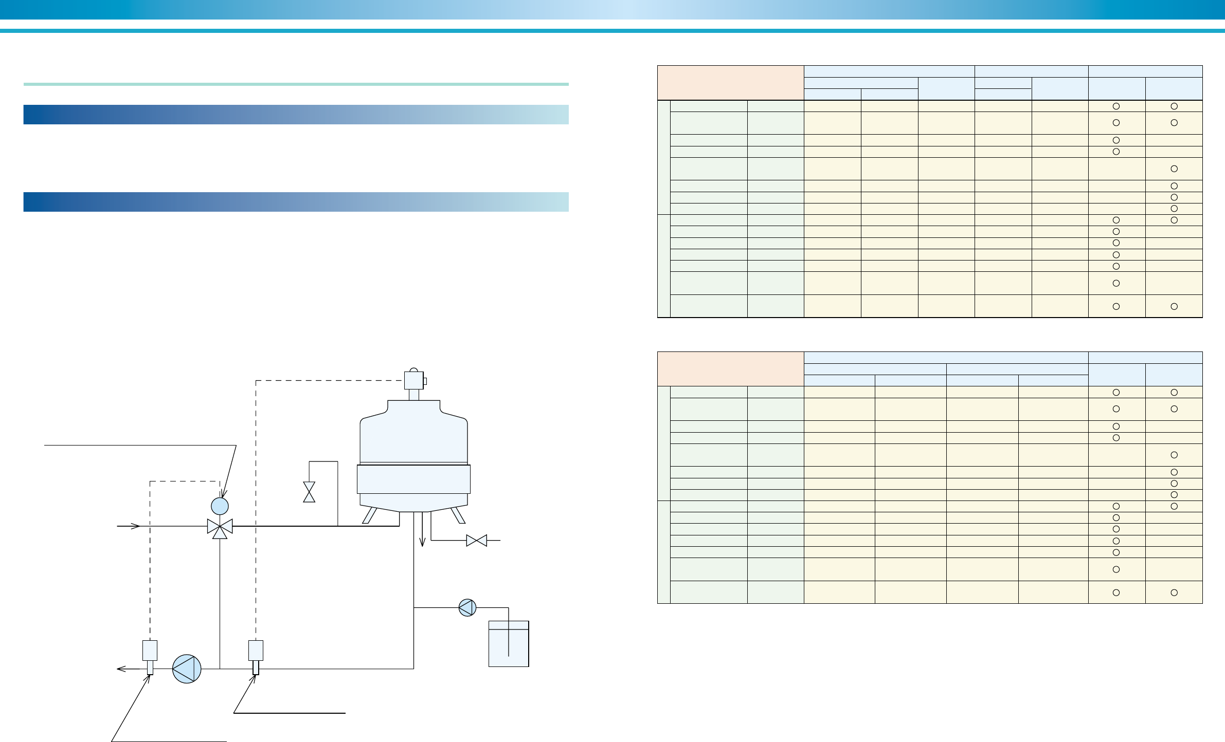
95
SUPER ABSORPTION
94
ENVIRONMENTALLY FRIENDLY TECHNOLOGY
The cooling water of an open-type recycling cooling tower lowers tem-
perature of the cooling water using vaporized latent-heat, and is reused.
At this time, the water is evaporated and dissolved salts. Hardness mate-
rials sulfate ion, etc. in the water will increase. Namely, condensation
phenomena of such materials occurs in the water, and water quality will
Quality control of cooling water
gradually be degraded. As the water and air always come in contact with
each other in the cooling tower, sulfurous acid gas, dust, sand and etc. in
the atmosphere will mix into the water, further degrading the water qual-
ity. In the cooling water system, problems with water are caused by these
factors. Typical problems are corrosion, scales and slimes.
As with any system utilizing an open or closed loop water circuit, the use
of water treatment is a necessity to insure long life and efficient operation
of the entire system.
Impurities in the water such as scale, dirt, bacteria, etc. will adhere to
heat transfer surfaces causing a loss of efficiency, higher operating costs,
and a potential for mechanical damage.
Proper and continued water treatment by a reputable water treatment
company should be continued for the life of the equipment. Water treat-
Water treatment
ment specialists can also help determine the necessary time intervals for
tube inspections and/or tube brushing/cleaning.
Added attention must be given on retrofit jobs when the existing piping is
reused. Air infiltration into the piping will cause a rapid build-up of rust
and corrosion inside the piping. Scale and debris may break loose from
the inside walls of the piping during retrofit operations. The use of water
strainers and water treatment will be necessary to remove the larger par-
ticles from the system and keep the smaller particles in suspension.
Notes :
1) The nomenclature of items, definition of terms and units shall comply with the JIS K 0101.
2) The mark K indicates factors affecting the corrosive or scale-forming tendencies.
3) When temperature is high (above 40°C), corrosiveness generally increases.
Especially, when the iron/steel surface has no protective film and directly contacts water,
it is desirable to adequately take countermeasures against corrosion, such as the addition of a
corrosion inhibitor and deaeration treatment.
4) As for the cooling water system using a closed type cooling tower, the water quality standard for
the mid-range temperature water system shall be applied to the closed circuit recirculating/sprinkling
water and its make-up water, while the water quality standard for the recirculating cooling water
system shall be applied to the sprinkling water and its make-up water, respectively.
5) City water, industrial water and ground water shall be used as source water, and demineralized water
reclaimed water, softened water, etc. shall be excluded.
6) The 15 items listed above show typical factors of corrosion and scale problems.
Cooling water thermostat
for cooling tower fan
Constant flow
blow valve
Cooling tower
Blow
Water supply
Chemicals adding pump
Chemicals tank
To chiller
From chiller
Cooling
Water pump
MV
Cooling water thermostat
for three-way control valve
Automatic three way control valve
Cooling water system
Reference items Standard items
Chilled water system Tendency
Recirculating type
Table 19. Water quality standard values for cooling water and chilled water
Table 20. Water quality standard values for mid-range temperature water
Recirculating
pH(25°C)
Electrical
conductivity 25°C
Chloride ion
Sulfate ion
Acid consumption
pH 4.8
Total hardness
Calcium hardness
Ionic silica
Iron
Copper
Sulfide ion
Ammonium ion
Residual chlorine
Free carbon
dioxide
Ryzner stability
index
(ms / m)
(mgCI- / I)
(mgSO
42
- / I)
(mgCaCO
3
/ I)
(mgCaCO
3
/ I)
(mgCaCO
3
/ I)
(mgSiO
2
/ I)
(mgFe / I)
(mgCu / I)
(mgS
2
- / I)
(mgNH
4
+ / I)
(mgCI / I)
(mgCO
2
/ )
(RSI)
6.5 to 8.2
80 or less
200 or less
200 or less
100 or less
200 or less
150 or less
50 or less
1.0 or less
0.3 or less
No detected
1.0 or less
0.3 or less
4.0 or less
60 to 7.0
6.0 to 8.0
30 or less
50 or less
50 or less
50 or less
70 or less
50 or less
30 or less
0.3 or less
0.1 or less
No detected
0.1 or less
0.3 or less
4.0 or less
***
7.0 to 8.0
30 or less
50 or less
50 or less
50 or less
70 or less
50 or less
30 or less
1.0 or less
1.0 or less
No detected
0.3 or less
0.25 or less
4.0 or less
***
7.0 to 8.0
30 or less
50 or less
50 or less
50 or less
70 or less
50 or less
30 or less
1.0 or less
1.0 or less
No detected
0.1 or less
0.3 or less
4.0 or less
***
7.0 to 8.0
30 or less
30 or less
30 or less
50 or less
70 or less
50 or less
30 or less
1.0 or less
1.0 or less
No detected
0.1 or less
0.1 or less
4.0 or less
***
7.0 to 8.0
30 or less
30 or less
30 or less
50 or less
70 or less
50 or less
30 or less
0.3 or less
0.1 or less
No detected
0.1 or less
0.3 or less
4.0 or less
***
6.8 to 8.0
40 or less
50 or less
50 or less
50 or less
70 or less
50 or less
30 or less
1.0 or less
1.0 or less
No detected
1.0 or less
0.3 or less
4.0 or less
***
6.8 to 8.0
40 or less
50 or less
50 or less
50 or less
70 or less
50 or less
30 or less
1.0 or less
1.0 or less
No detected
1.0 or less
0.3 or less
4.0 or less
***
6.8 to 8.0
30 or less
50 or less
50 or less
50 or less
70 or less
50 or less
30 or less
0.3 or less
0.1 or less
No detected
0.1 or less
0.3 or less
4.0 or less
***
Make-up water
Once through
(One way) type Make-up water Corrosive Scale forming
below 20°C
Recirculating
Mid-range temperature (20-90°C) water system
Reference items Standard items
Tendency
Lower level (20 to 60°C) Higher level (60 to 90°C)
Recirculating
pH(25°C)
Electrical
conductivity 25°C
Chloride ion
Sulfate ion
Acid consumption
pH 4.8
Total hardness
Calcium hardness
Ionic silica
Iron
Copper
Sulfide ion
Ammonium ion
Residual chlorine
Free carbon
dioxide
Ryzner stability
index
(ms / m)
(mgCI- / I)
(mgSO
42
- / I)
(mgCaCO
3
/ I)
(mgCaCO
3
/ I)
(mgCaCO
3
/ I)
(mgSiO
2
/ I)
(mgFe / I)
(mgCu / I)
(mgS
2
- / I)
(mgNH
4
+ / I)
(mgCI / I)
(mgCO
2
/ )
(RSI)
Make-up waterRecirculating Make-up water Corrosive Scale forming
Figure 69. Temperature control of cooling water
Management of cooling water quality
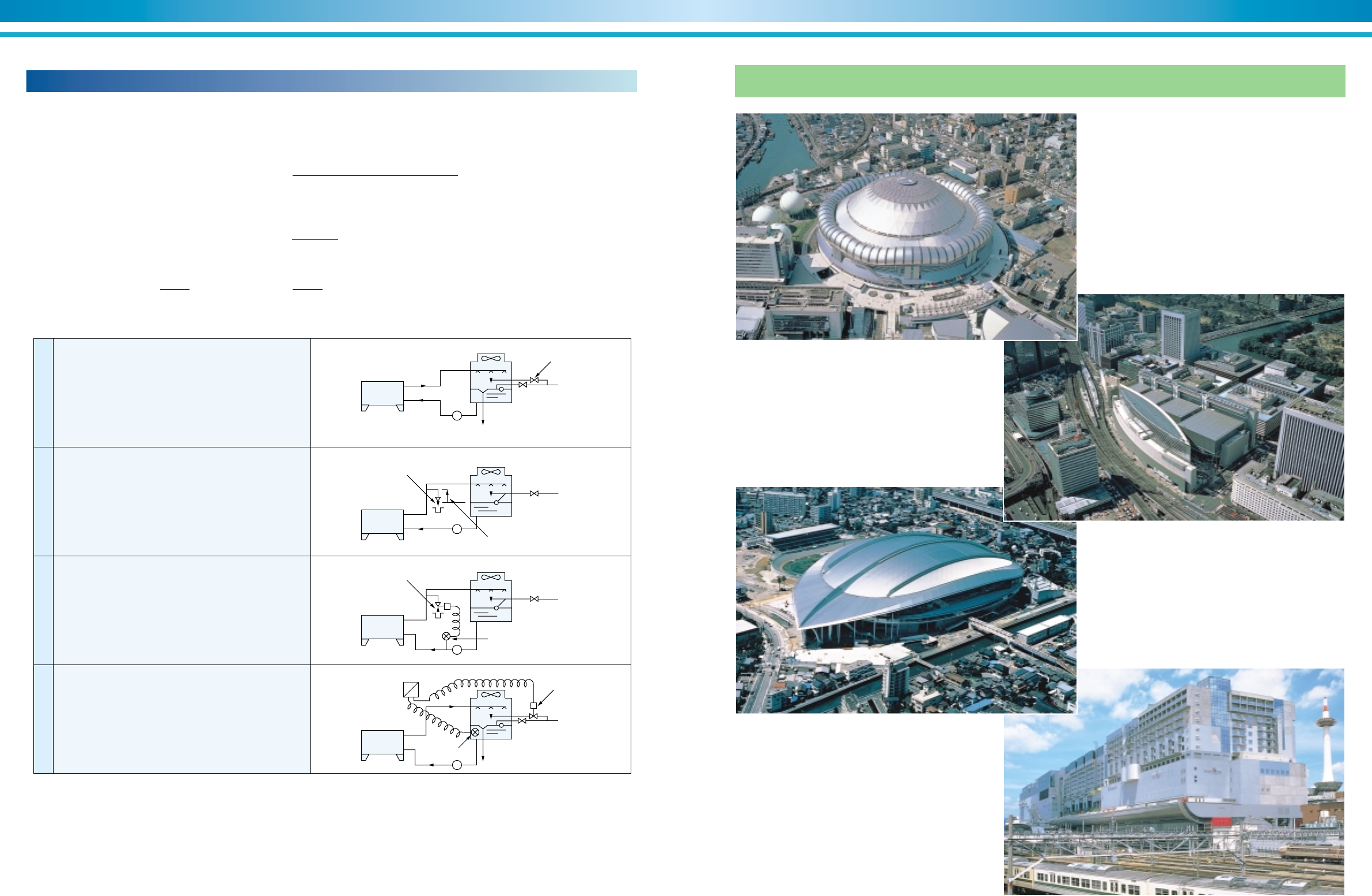
97
SUPER ABSORPTION
96
ENVIRONMENTALLY FRIENDLY TECHNOLOGY
Examples of Installation
Osaka Dome City User : OSAKA GAS Co.,Ltd. Iwasaki Energy Center
TOKYO INTERNATIONAL FORUM User : Tokyo Heat Supply Co.,ltd
Kitakyusyu Media Dome
Kyoto Station Building
Cooling water blow system
A part of circulating water should be blown to prevent degrading of cooling water quality.
Since concentration ratio is considered about 3 to 4 blowing, water quantity is calculated as follows.
N : Concentration ratio generally N=3
M : Make-up water volume
3,024✕1.85 (exhaust factor)
E : Evaporation loss E= 575 (Latent heat of evaporation at 40°C)
W : Splashing loss generally W=0.2% of circulating water volume
B : Blow volume
E+W+B
M : E+W+B N= W+B
by the above,
1N
B= • (E+W-NW) M= •E
N-1 N-1
Absorption
chiller
Over flow
Over flow
Blow regulation valve
Solenoid valve
Solenoid valve
Pressure switch
Higher than
cooling water level
Sensor
Water treatment control panel
Make-up
water
Manual valve
Figure 70.
Figure 71.
Figure 72.
Figure 73.
Make-up
water
Make-up
water
Make-up
water
Absorption
chiller
Absorption
chiller
Absorption
chiller
P
P
P
P
1
2
3
4
Over Flow
Make-up water is over supplied
by manual valve for over-flow
in cooling tower.
Continuous Flow
Certain amount of circulating
water is blown by blow
regulation valve.
Pressure Switch+Solenoid Valve
Circulation pump is controlled
by pressure switch.
Conductivity Meter+Solenoid Valve
PH Meter+Solenoid Valve
Blow is controlled.
