Sanyo Refrigerator Mpr 311Dh Users Manual
MPR-311D(H) to the manual beed74e8-7bc9-4de2-bca5-0e791e7952e6
2015-01-26
: Sanyo Sanyo-Refrigerator-Mpr-311Dh-Users-Manual-338146 sanyo-refrigerator-mpr-311dh-users-manual-338146 sanyo pdf
Open the PDF directly: View PDF ![]() .
.
Page Count: 20
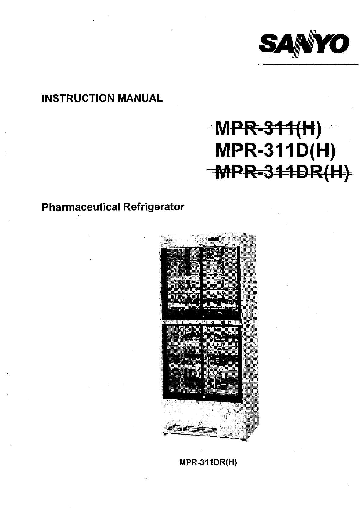
INSTRUCTION MANUAL
Pharmaceutical Refrigerator
=MPR-311
(II)
MPR-3110(H)
---MPR-314DR{II}
MPR-311 DR(H)
Note:
1. No
part
of
this
manual may be reproduced in
any
form
with
the expressed
written
permission
of
SANYO.
2. The
contents
of
this
manual are
subject
to
change
without
notice.
3. Please
contact
SANYO
if
any
point
in
this
manual is
unclear
or
if
there are
any
inaccuracies.
SANYO Electric Co., Ltd. All rights reserved. Printed
in
Japan.
CONTENTS
PRECAUTIONS FOR SAFE OPERATION
P.
1
CAUTIOINS FOR USAGE
P.5
NAME AND FUNCTION OF PARTS
P.
6
BEFORE COMMENCING OPERATION
P.8
AUTOMATIC TEMPERATURE RECORDER
P.10
START-UP OF UNIT
P.
11
OPERATING INSTRUCTIONS
P.
12
MAINTENANCE
P.
14
TROUBLE SHOOTING
P.
15
ENVIRONMENTAL CONDITIONS
P.15
DISPOSAL
OF
UNIT
P.
15
SPECIFICATIONS
P.
16
PERFORMANCE
P.
16
SAFETY CHECK SHEET
P.
17
1
PRECAUTIONS FOR
SAFE OPERATION
It is imperative that the user
complies with this manual
as
it
contains important safety
advice.
Items and procedures are described so that
you can use this unit correctly and safely. If
the precautions advised are followed, this will
prevent possible damage to the user and any
other person.
Precautions are illustrated
in
the following
way:
~WARNING
Failure to observe WARNING signs
could result
in
a hazard to personnel
possibly resulting
in
serious injury or
death.
~CAUTION
Failure to observe CAUTION signs
could result
in
injury to personnel and
damage to the unit and associated
property.
Symbol shows;
~
L::,
this symbol means caution.
o
iSl
this symbol means
an
action
is
prohibited.
o • this symbol means
an
instruction must be
followed.
Be
sure to keep this manual
in
a place
accessible to users
of
this unit.
PRECAUTIONS FOR SAFE OPERATION
o
o
o
o
e
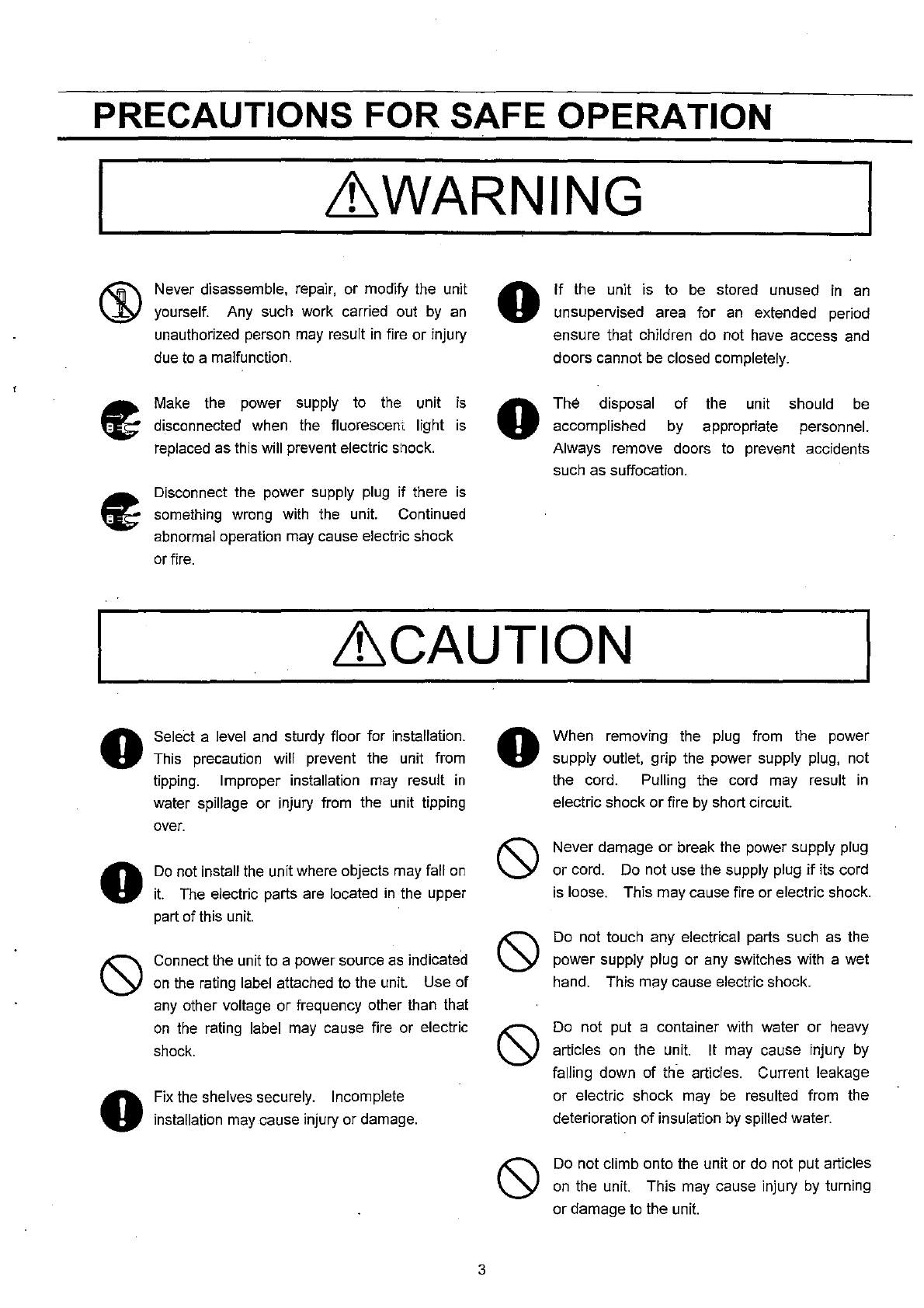
~WARNING
Do
not use the unit outdoors. Current
leakage or electric
shOck
may result
if
the
unit
is exposed to rainwater.
Only qualified engineers or service personnel
should install the unit. The installation
by
unqualified personnel may cause gas or liquid
leakage, electric shock or fire.
Be
sure
to
install the unit
on
a sturdy floor.
If
the floor
is
not strong enough
or
the installation
site is not adequate, this may result
in
injury
from the unit falling or tipping over.
Never install the unit
in
a humid place or a
place where it is likely
to
be
splashed
by
water.
Deterioration of the insulation may result which
could cause current leakage
or
electric shock.
Never install the unit
in
a flammable or volatile
location. This may cause explosion
or
fire.
Never install the unit where acid or corrosive
gases are present as current leakage or
electric shock may result due to corrosion.
Make sure a dedicated power source
is
used
as indicated
on
the
rating label attached
to
the
unit.
Make sure to remove dust from the power
supply
plug
before inserting
in
a power source.
A dusty plug or improper insertion may pose a
hazard.
Use a power supply outlet with ground (earth)
to prevent electric shock. If the power supply
outlet
is
not grounded, it will
be
necessary
to
install a ground
by
qualified engineers.
2
o
o
Never ground the unit through a gas pipe,
water
main,
telephone line or lightening
rod.
Such grounding may cause electric shock
in
the case of
an
incomplete circuit.
Do
not insert metal objects such as a
pin
or a
wire into any vent, gap or any outlet for inner
air circulation. This may cause electric shock
or injury
by
accidental contact with moving
parts.
Never store volatile or flammable substances
in
this unit. This may cause explosion or fire.
Never store corrosive substances in this unit.
This may
lead
to
damage to the inner
components or electric parts.
Make sure to use this unit
in
safe area when
treating the poison, harmful or radiate articles.
Improper use may cause
bad
effect
on
your
health or environment.
Make sure
to
prepare a safety check sheet
when
you
request
any
repair or maintenance
fO!
the
safety of service personnel.
Always disconnect the power supply
to
the unit
prior
to
any repair or maintenance of the unit
in
order
to
prevent electric shock or injury.
Ensure
you
do
not inhale or consume
medication or aerosols from around the unit at
the time of maintenance. These may
be
harmful
to
your health.
Never splash water directly onto the unit as this
may cause electric shock or short circuit.
PRECAUTIONS FOR SAFE OPERATION
I
o
o
o
~WARNING
Never disassemble, repair, or modify the unit
yourself. Any such work carried out
by
an
unauthorized person may result
in
fire or injury
due
to
a malfunction.
Make the power supply to
the
unit
is
disconnected when the fluorescent light
is
replaced as this will prevent electric
S110ck.
Disconnect the power supply
plug
if
there
is
something wrong with the unit. Continued
abnormal operation may cause electric shock
or
fire.
o
o
If
the unit is to
be
stored unused
in
an
unsupervised area for
an
extended period
ensure that children
do
not have access
and
doors cannot
be
closed completely.
The disposal
accomplished
of
by
the unit should
be
appropriate personnel.
Always remove doors
to
prevent accidents
such as suffocation.
~CAUTION
Select a level
and
sturdy floor for installation.
This precaution will prevent the unit from
tipping. Improper installation may result
in
water spillage or injury from the unit tipping
over.
Do
not install the unit where objects may fall
on
it.
The
electric parts are located
in
the upper
part of this unit.
Connect the unit
to
a power source
as
indicated
on
the
rating label attached to the unit. Use of
any
other voltage or frequency other than that
on
the
rating label
may
cause fire or electric
shock.
Fix
the
shelves securely. Incomplete
installation may cause injury or damage.
3
o When removing the
plug
from the power
supply outlet, grip the power supply plug, not
the cord.
PUlling
the cord may result
in
electric shock or fire
by
short circuit.
Never damage or break
the
power supply plug
or cord.
Do
not use the supply plug
if
its cord
is
loose. This may cause fire or electric shock.
Do not touch any electrical parts such
as
the
power supply plug or any switches with a wet
hand. This may cause electric shock.
Do
not put a container with water or heavy
articles
on
the unit. It may cause injury
by
falling down of
th·e
articles. Current leakage
or electric shock may
be
resulted from the
deterioration of insulation
by
spilled water.
Do
not climb onto the unit or
do
not put articles
on
the unit. This may cause injury
by
turning
or damage
to
the unit.
PRECAUTIONS FOR SAFE OPERATION
o
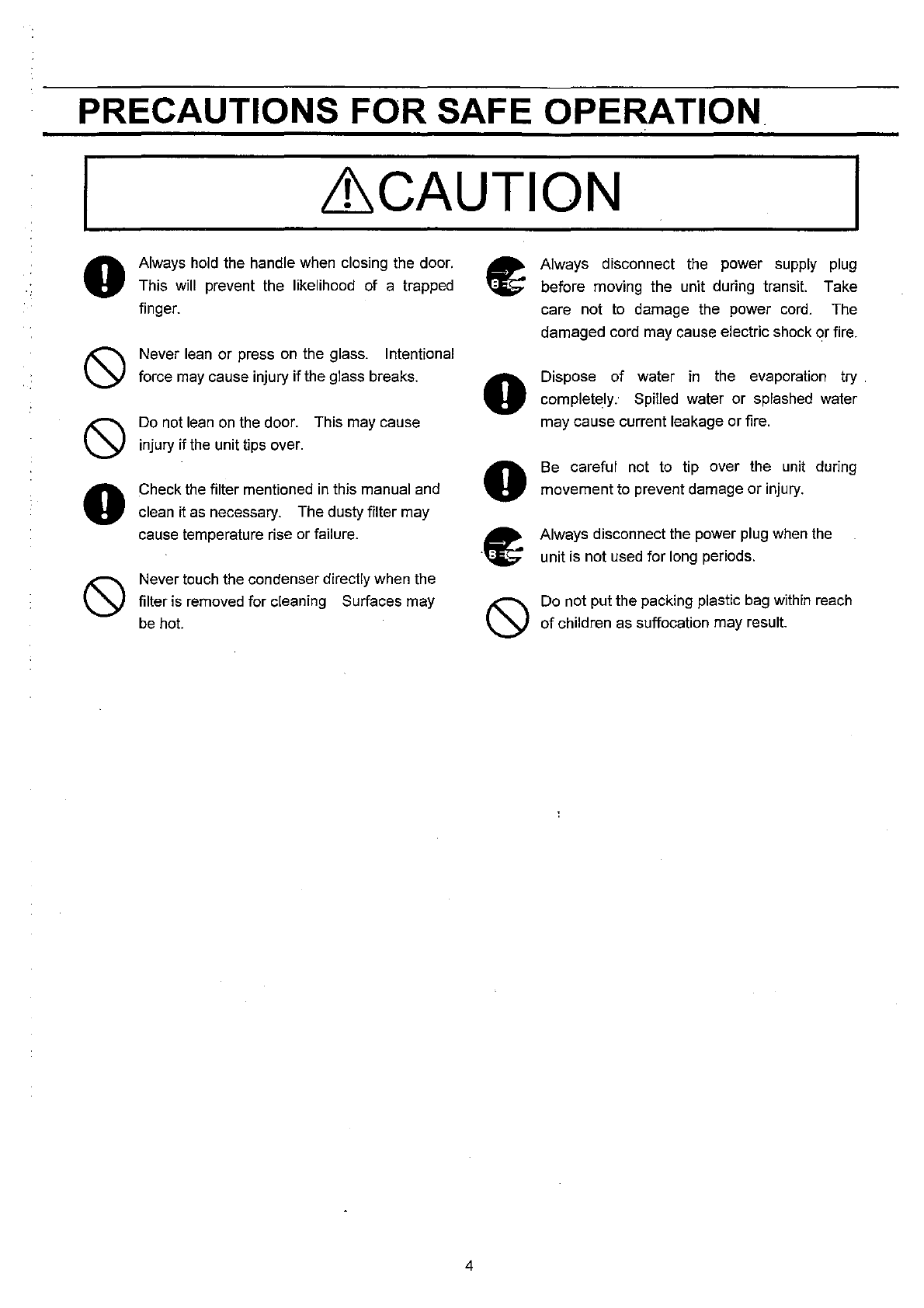
~CAUTION
Always
hold
the handle when closing the door.
This will prevent the likelihood of a trapped
finger.
Never
lean
or press
on
the glass. Intentional
force may cause injury if the glass breaks.
Do
not
lean
on
the door. This may cause
injury if
the
unit tips over.
Check
the
filter mentioned
in
this manual and
clean it
as
necessary. The dusty filter may
cause temperature rise or failure.
Never touch the condenser directly when the
filter is removed for cleaning Surfaces may
be
hot.
4
o
o
c
Always disconnect the power supply
plug
before moving the unit during transit. Take
care not
to
damage the power
cord.
The
damaged cord may cause electric shock or fire.
Dispose of water
in
the evaporation
try.
completely. Spilled water or splashed water
may cause current leakage or fire.
Be careful not to tip over the unit during
movement
to
prevent damage
or
injury.
Always disconnect the power plug
when
the
unit is not used for long periods.
Do not put the packing plastic
bag
within reach
of
children as suffocation may result.
CAUTIONS FOR USAGE
G) If the unit
is
unplugged or the power to the unit
is
interrupted,
do
not restart the unit for at least 5 minutes.
This protects the compressor.
® This inner cabinet
is
refrigerated
by
the forced
circulation of cooled air inside the chamber.
Ensure
that the intake and exhaust vents are not blocked.
@ Adequate space should
be
provided between
the
items inside the unit to allow air circulation.
@ Never store corrosive materials such as
acid
or
alkali unless the container
is
completely sealed
up.
Corrosion may lead to failure
of
the unit
in
time.
@ Once the chamber temperature has stabilized,
put
the items into the chamber
in
small batches
to
minimize the temperature increase.
® Fix the shelves securely. Place items
on
the
shelves
and
leave a space between the walls of
the
cabinet
and
the contents
to
allow air circulation.
Do
not place items
on
the floor of the chamber.
(J)
When
the
power plug-in the unit, the fan does
not
always operate immediately. After a few minutes,
the
fan operates properly.
® For some time after
the
unit has been started, or
when the ambient temperature
is
fairly high, the cabinet
walls may heat
up.
This does not indicate a
malfunction. It indicates that the dew
preventative/power economy function
is
performing
satisfactorily. Hot gases are piped from the motor
compressor along the front edges of the cabinet to
prevent dew condensation.
@ If condensation forms
on
the front glass
or
frame
surface, wipe it off with a soft, dry cloth.
@l
Do
not clean the unit with scrubbing brushes, acid,
thinner, solvents, powdered soap, cleanser
or
hot water.
These agents
can
scratch the paint or cause it to peel.
Plastic and rubber parts
can
be
easily damaged by
these materials, especially solvents. When a neutral
detergent
is
used
to
clean
the unit, rinse thoroughly
with a cloth soaked
in
clean
water.
!TIl
If
an
instrument requiring a power source is to be
placed inside the cabinet, the cable
can
be
led through
the access port
on
the
left hand side of the cabinet.
After installation, a rubber cap should
be
used
to
seal
the access
port.
Failure to
do
this
can
affect the
temperature uniformity inside the cabinet and lead to
condensation
on
the outside of the access port.
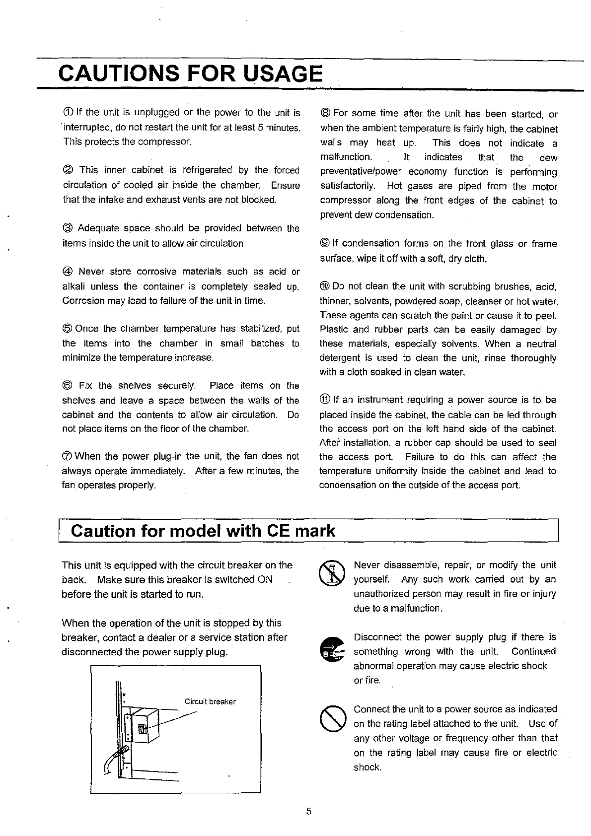
Caution for model with
CE
mark
This unit is equipped with the circuit breaker
on
the
back. Make sure this breaker is switched ON
before the unit is started to run.
When
the operation
of
the unit is stopped by this
breaker, contact a dealer
or
a service station after
disconnected the power supply plug.
•
Circuit
breaker
t:JZ::;:::r-
5
Never disassemble, repair, or modify the unit
yourself. Any
such
work carried out
by
an
unauthorized person may result
in
fire
or
injury
due
to
a malfunction.
Disconnect the power supply
plug
if there is
something wrong with the unit. Continued
abnormal operation may cause electric shock
or fire .
Connect the unit
to
a power source as indicated
on
the rating
label
attached
to
the unit. Use of
any other voltage or frequency other than that
on
the
rating
label
may cause fire or electric
shock.
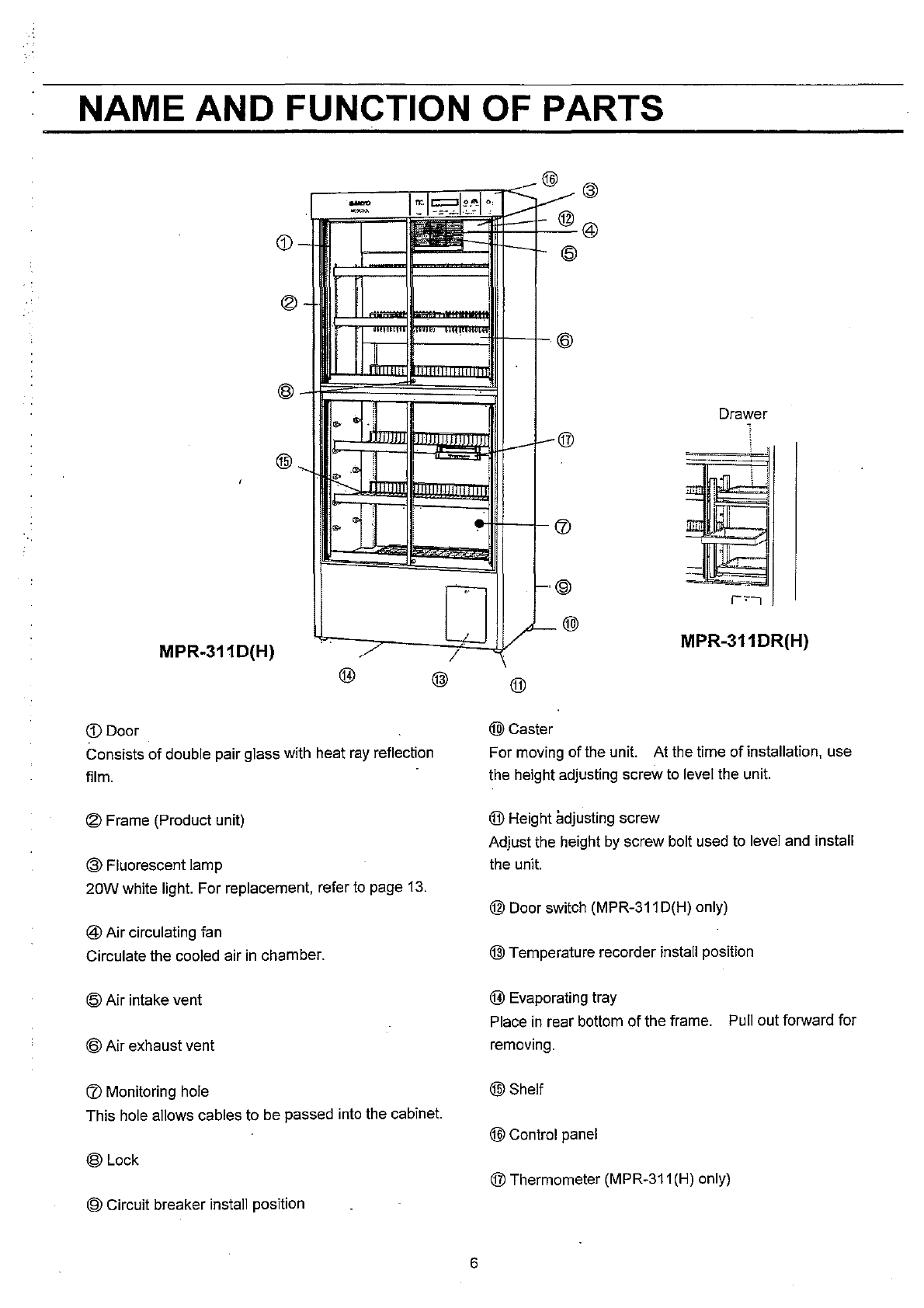
NAME AND FUNCTION OF PARTS
.-.
ii~r
.
..""'''
-
-~
---
@
(Q)
@
@
-
IIIII
il
'
..
1 i
"-
~
I
,
..
.
MPR-311 D(H)
([)
Door
Consists
of
double pair glass with heat
ray
reflection
film.
® Frame (Product unit)
@ Fluorescent lamp
20W
white light. For replacement, refer to page
13.
@ Air circulating fan
Circulate the cooled air
in
chamber.
(Q)
Air intake vent
@ Air exhaust vent
CD
Monitoring hole
This hole allows cables to be passed into the cabinet.
@Lock
® Circuit breaker install position
,..
r-;c-
..L
I
6
i
i @
;
, -
-®
\lJ
1-,@
I~@
®
@Caster
Drawer
."
_
..
_.
__
.L~
-_._
.•
__
.•
--<.
MPR-311DR(H)
For moving
of
the unit. At the time
of
installation, use
the height adjusting screw to level the unit.
® Height adjusting screw
Adjust the height
by
screw bolt used to level and install
the unit.
@ Door switch (MPR-311 D(H) only)
@ Temperature recorder install position
@ Evaporating tray
Place
in
rear bottom
of
the frame. Pull out forward for
removing.
@Shelf
@ Control panel
® Thermometer (MPR-311 (H) only)
NAME AND FUNCTION OF PARTS
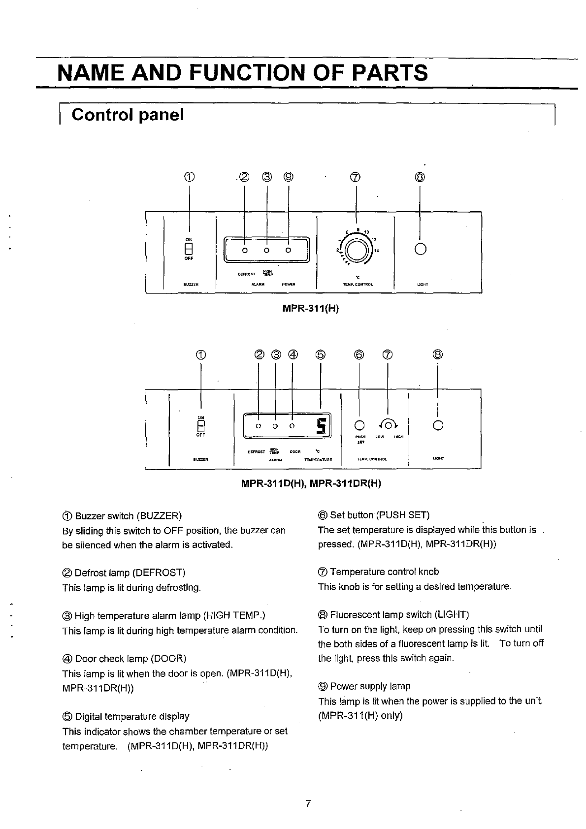
I Control panel
®
0'
0'
II
II
El
0 0 0
\,0
" 0
0"
DEFROST
""
~"
"
. -_:.All
..
._.
TeMP.
CONTROL
UGHT
MPR·311(H)
®@@
@ ®
0'
II
sll
AA
El
0 0 0 0 0
0"
~~
'ow
"~
,~
DEFROST
w,'m.
o~.
"
.=.
.~-
lEMPERATIJRE
lEMP.
CONTROL
UGHT
MPR·311D(H), MPR·311DR(H)
cD
Buzzer switch (BUZZER)
By
sliding this switch to OFF position, the buzzer can
be silenced when the alarm is activated.
® Defrost lamp (DEFROST)
This lamp is lit during defrosting.
@ High temperature alarm lamp (HIGH TEMP.)
This lamp is lit during high temperature alarm condition.
@ Door check lamp (DOOR)
This lamp is lit when the door is open. (MPR·311 D(H),
MPR·311 DR(H))
@ Digital temperature display
This indicator shows the chamber temperature or set
temperature. (MPR·311D(H), MPR·311DR(H))
7
@ Set button (PUSH SET)
The set temperature
is
displayed while this button is
pressed. (MPR·311D(H), MPR·311DR(H))
r:v
Temperature control knob
This knob is for setting a desired temperature.
® Fluorescent lamp switch (LIGHT)
To turn
on
the light, keep
on
pressing this switch until
the both sides
of
a fluorescent lamp is lit. To turn off
the light, press this switch again.
® Power supply lamp
This lamp is lit when the power is supplied to the unit.
(MPR·311(H) only)
BEFORE COMMENCING OPERATION
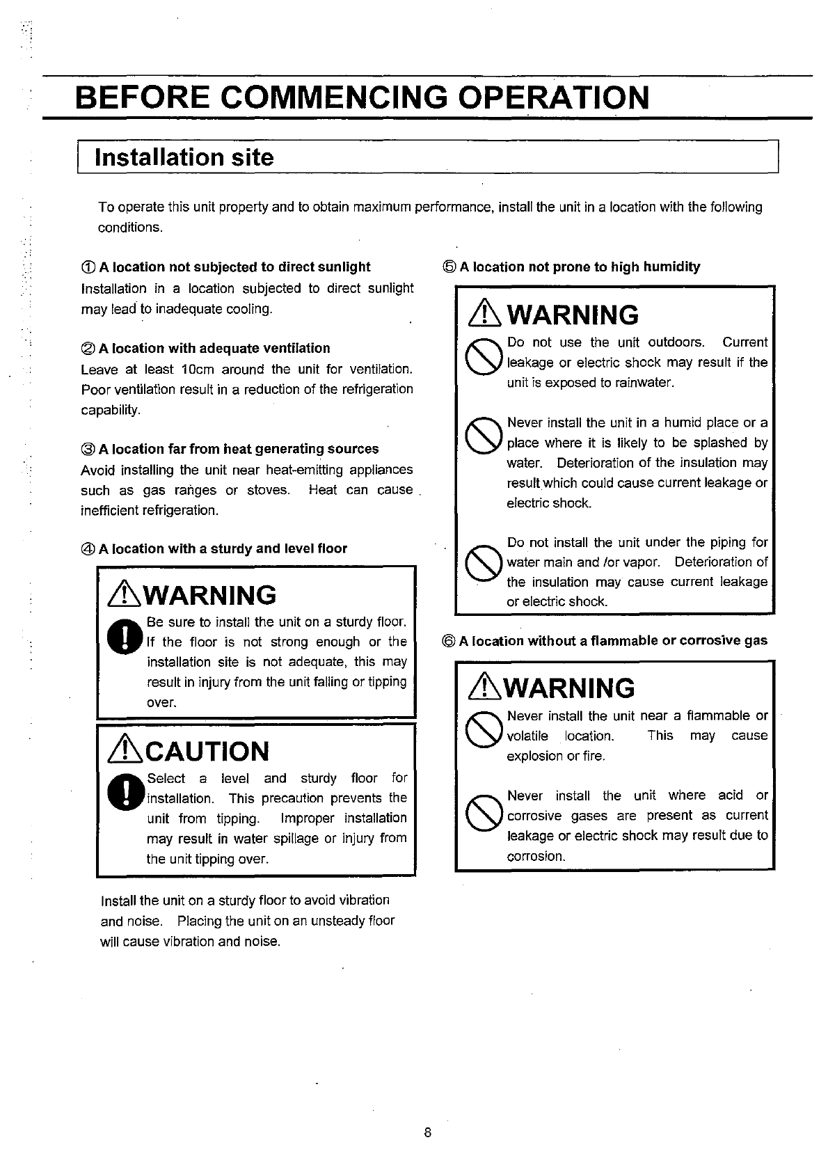
Installation site
To operate this unit property and
to
obtain maximum performance, install the unit
in
a location with the following
conditions.
<D
A location not subjected to direct sunlight
Installation
in
a location subjected
to
direct sunlight
may
lead·
to
inadequate cooling.
® A location with adequate ventilation
Leave at least 10cm around the unit for ventilation.
Poor ventilation result
in
a reduction of the refrigeration
capability.
@ A location far from heat generating sources
Avoid installing the unit near heat-emitting appliances
such as gas ranges or stoves. Heat
can
cause.
inefficient refrigeration.
@ A location with a sturdy and level floor
&'WARNING
o Be sure to install the unit
on
a sturdy floor.
If the floor is not strong enough or the
installation site
is
not adequate, this may
result
in
injury from the unit falling or tipping
over.
~CAUTION
o Select a level and sturdy floor for
installation. This precaution prevents the
unit from tipping. Improper installation
may result
in
water spillage or injury from
the unit tipping over.
Install the unit
on
a sturdy floor
to
avoid vibration
and noise. Placing the unit
on
an
unsteady floor
will cause vibration
and
noise.
8
@ A location not prone to high humidity
&'WARNING
'"
Do
not use the unit outdoors. Current
\.Y
leakage or electric shock may result if the
unit
is
exposed
to
rainwater.
'"
Never install the unit
in
a humid place or a
\.Y
place where it is likely to
be
splashed
by
water. Deterioration
of
the insulation may
resultwhich could cause current leakage or
electric shock.
'"
Do
not install the unit under the piping for
\.Y
water main and lor vapor. Deterioration of
. the insulation may cause current leakage
or electric shock.
@ A location without a flammable
or
corrosive gas
&'WARNING
'"
Never install the unit near a flammable or
\.Y
volatile location. This may cause
explosion or fire.
'"
Never install the unit where acid or
\.Y
corrosive gases are present as current
leakage or electric shock may result due to
corrosion.
BEFORE COMMENCING OPERATION
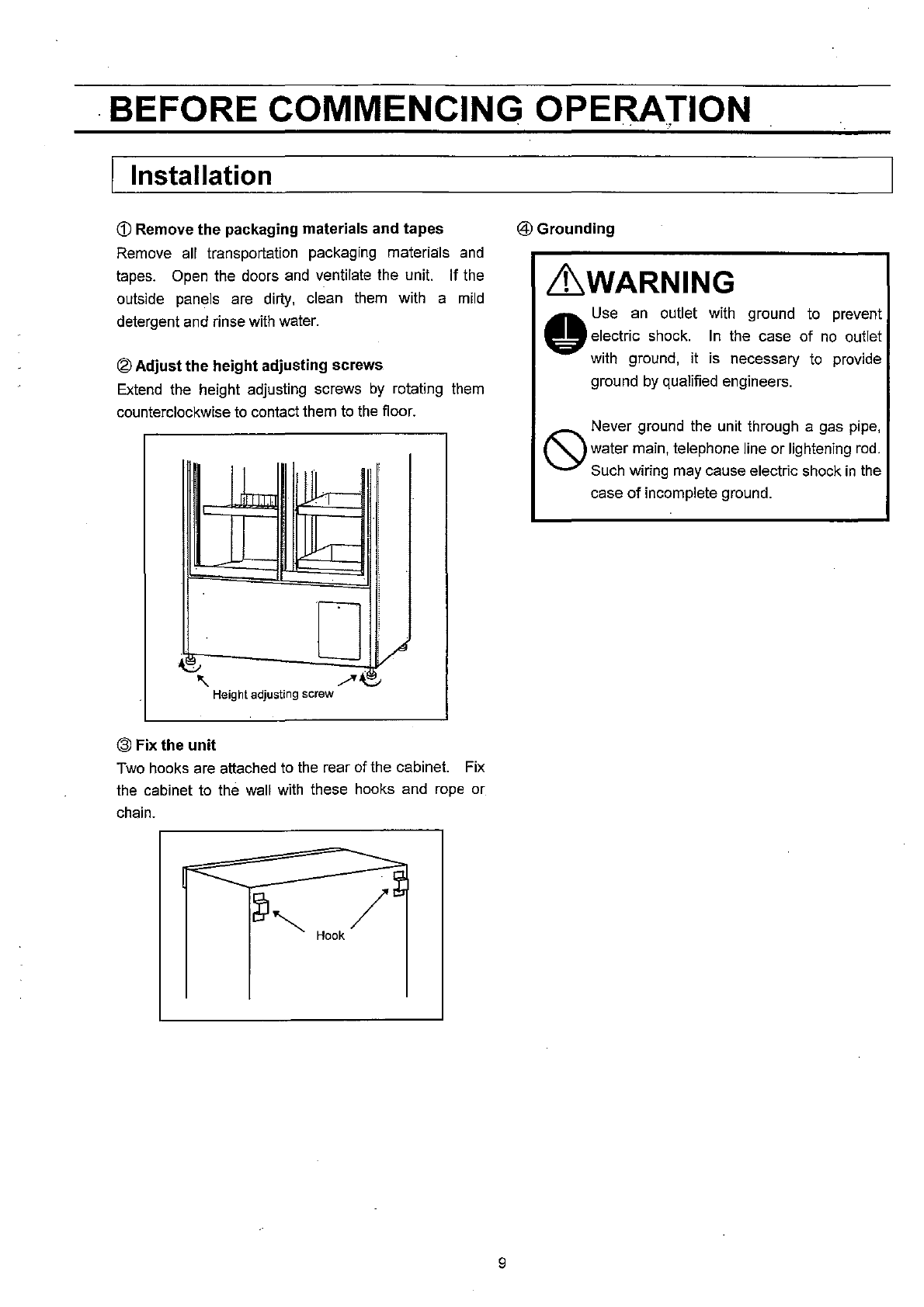
I Installation
<D
Remove
the
packaging materials and tapes
Remove all transportation packaging materials
and
tapes. Open the doors
and
ventilate the unit. If the
outside panels are dirty, clean them with a
mild
detergent and rinse with water.
®
Adjust
the
height adjusting screws
Extend
the height adjusting screws
by
rotating them
counterclockwise
to
contact them to
the
floor.
lb
JJ
~I
!
0
l/
e
'\
./"~
Height
adjusting
screw
@ Fix the
unit
Two hooks are attached
to
the
rear of the cabinet. Fix
the cabinet to the wall with these hooks and
rope
or
chain.
='"""-=-......,=
-=
-==~-
---:-~~.
~
~"
/
Hook
9
. . .
"'
@Grounding
&WARNING
..
Use
an
outlet with ground
to
prevent
velectric
shock.
In
the case of
no
outlet
with ground, it is necessary
to
provide
ground
by
qualified engineers.
Never ground the unit through a gas pipe,
o water main, telephone line or lightening
rod.
Such wiring may cause electric shock
in
the
case
of
incomplete ground.
AUTOMATIC TEMPERATUER RECORDER
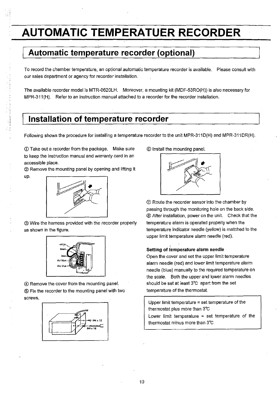
I Automatic temperature recorder (optional)
To record the chamber temperature, an optional automatic temperature recorder is available. Please consult with
our sales department
or
agency for recorder installation.
The available recorder model is MTR-0620LH. Moreover, a mounting kit (MDF-53RO(H)) is also necessary for
MPR-311 (H). Refer to an instruction manual attached to a recorder for the recorder installation .
. 1 Installation
of
temperature recorder
Following shows the procedure for installing a temperature recorder to the unit MPR-311 D(H) and MPR-311 DR(H).
(j)
Take out a recorder from the package. Make sure
to keep the instruction manual and warranty card
in
an
accessible place.
@ Remove the mounting panel by opening and lifting it
up.
.'"-....
® Wire the harness provided with the recorder properly
as shown
in
the figure.
@ Remove the cover from the mounting panel.
® Fix the recorder to the mounting panel with two
screws.
10
® Install the mounting panel.
r:J)
Route the recorder sensor into the chamber
by
passing through the monitoring hole
on
the back side.
@ After installation, power
on
the unit. Check that the
temperature alarm is operated properly when the
temperature indicator needle (yellow) is matched to the
upper limit temperature alarm needle (red).
Setting
of
iemperature alarm needle
Open the cover and set the upper limit temperature
alarm needle (red) and lower limit temperature alarm
needle (blue) manually to the required temperature
on
the scale. Both the upper and lower alarm needles
should be set at least
3°C
apart from the set
temperature
of
the thermostat.
Upper limit temperature = set tem perature of the
thermostat plus more than
3°C
Lower limit temperature = set temperature
of
the
thermostat minus more than
3°C
START-UP OF UNIT
The following procedure should
be
adhered to for initial start-up and continuous operation.
<D
Connect unit to dedicated power supply. Do not put
any
product
in
the unit
at
this time.
® When the power
is
initially applied, the audible alarm
may sound. Set the BUZZER switch to OFF to silence
the alarm.
@ Set the desired temperature.
Handling
of
the containers
@ Check that the chamber temperature has reached to
the desired temperature.
@
When
you are satisfied that the unit
is
working
correctly, begin slowly placing product into the chamber
to minimize the temperature rise.
Arrange containers not to disturb air circulation
in
the unit. Disturbance
of
air circulation may cause freeze
of
containers or incline
of
temperature.
<D
Air
intake
vent
Avoid the disturbance
of
air circulation
in
the unit
by
containers. Disturbance
of
air circulation may causes
freeze
of
containers or incline
of
temperature.
®
Air
exhaust
vent
Do
not disturb the exhaust air port
by
putting containers
near the exhaust air port. Containers near the exhaust
air port may freeze when the unit runs with low
temperature (less than
5°C).
Note:
Never store the material of corrosive such
as
acid or
alkaline
of
which container is not sealed
up
completely.
It may cause poor cool
by
refrigerant leakage resulted
from corrosion
of
the evaporator.
~I
_D_ef_r_os_t_c~y_c_le_s
______________________________
~1
There are two types
of
defrost cycles present
in
this blood bank refrigerator, and both cycles occur automatically.
1. Cycle
defrost
To keep the temperature stable inside the chamber, the
refrigeration compressor
is
cycled
on
and off. During
the "off' periods
any
frost which has accumulated on
the refrigeration coils
is
melted
by
energizing a small
heater, this will not have any discernable effect on the
chamber temperature.
11
2.
Forced
defrost
When ambient humidity
is
high, or a large amount
of
damp product
is
being stored inside the refrigerator,
there is a possibility that cycle defrost may not be
enough to remove all
of
the frost
on
the refrigeration
coils. In this case, a forced defrost cycle will be
initiated. While the unit
is
operating under a forced
defrost cycle, the defrost lamp on the control panel will
be lit. Once the forced defrost cycle
is
complete,
normal operation will resume. The chamber
temperature rises to about
10°C
during the defrosting.
.-;
OPERATING INSTRUCTIONS
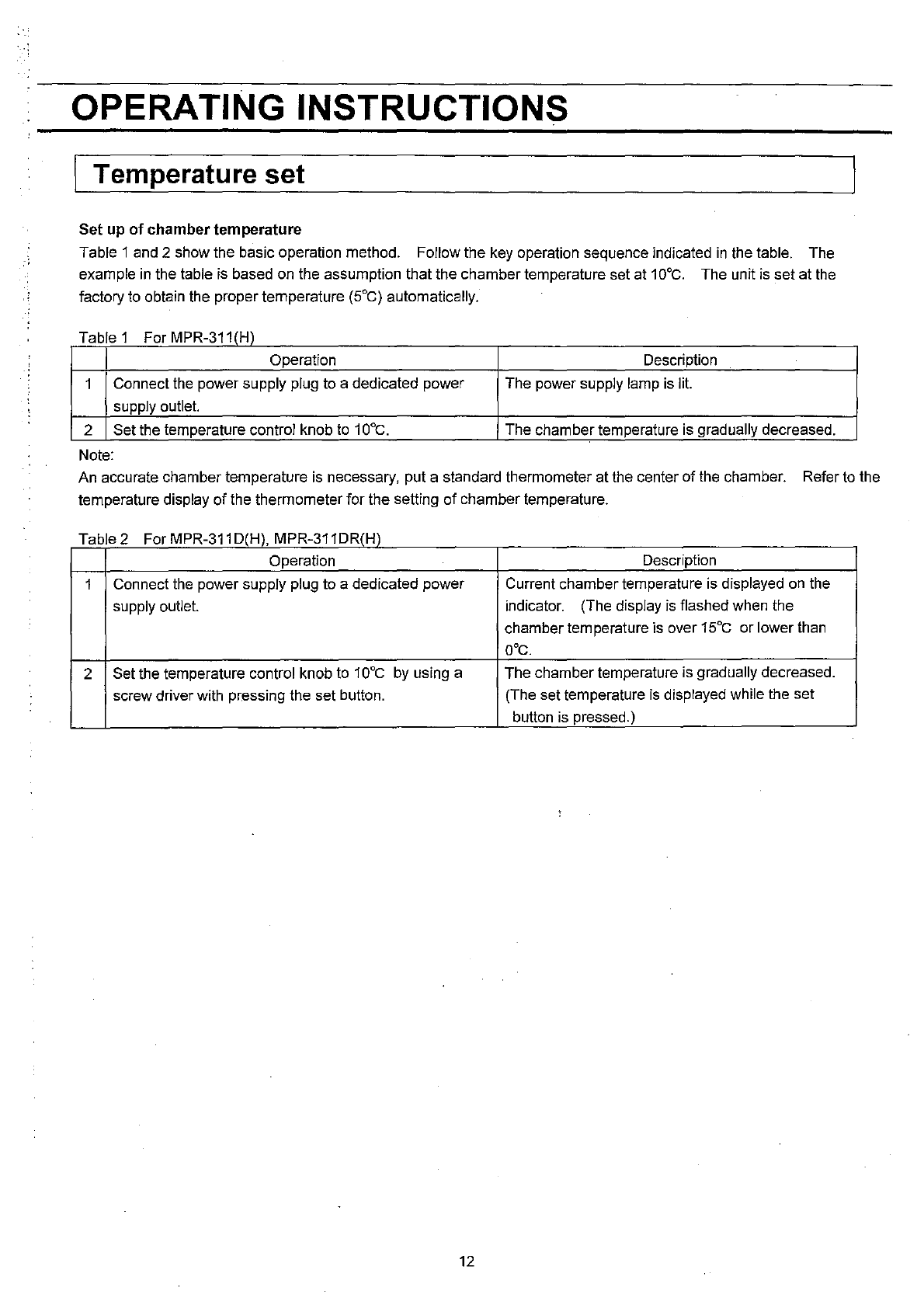
I Temperature set
Set
up
of
chamber
tern perature
Table 1 and 2 show the basic operation method. Follow the key operation sequence indicated
in
the table. The
example
in
the table is based on the assumption that the chamber temperature set at 1
GOC.
The unit is set at the
factory to obtain the proper temperature (5°C) automatically.
Table 1 For MPR-311 (H)
Operation Description
1 Connect the power supply plug to a dedicated power The power supply lamp is lit.
supply outlet.
2 Set the temperature control knob to 1
GOC.
The chamber temperature is gradually decreased.
Note:
An accurate chamber temperature is necessary, put a standard thermometer at the center
of
the chamber. Refer to the
temperature display
of
the thermometer for the setting
of
chamber temperature.
Table 2 For MPR-311 D(H), MPR-311 DR(H)
Operation Description
1 Connect the power supply plug to a dedicated power Current chamber temperature is displayed
on
the
supply outlet. indicator. (The display is flashed when the
chamber tem perature is over
15°C
or
lower than
aOc.
2 Set the temperature control knob to 1
GOC
by using a The chamber temperature is gradually decreased.
screw driver with pressing the set button. (The set temperature is displayed while the set
button is pressed.)
12
OPERATING INSTRUCTIONS
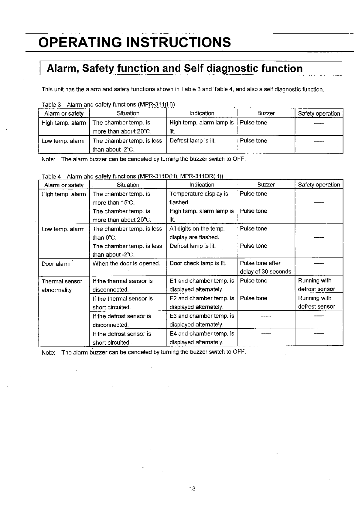
I Alarm, Safety function and Self diagnostic function
This unit has the alarm and safety functions shown
in
Table 3 and Table
4,
and also a self diagnostic function.
Table 3 Alarm and safety functions (MPR-311 H))
Alarm
or
safety Situation Indication Buzzer Safety operation
High temp. alarm
The
chamber temp. is High temp. alarm lamp is Pulse tone ~----
more than about 20°C. lit.
Low temp. alarm The chamber temp. is less Defrost lamp is lit. Pulse tone
-----
than about
_2°C.
Note: The alarm buzzer can be canceled
by
turning the buzzer switch to OFF.
Table 4 Alarm and safety functions (MPR-311 D(H), MPR-311 DR(H))
Alarm
or
safety Situation Indication Buzzer Safety operation
High temp. alarm
The
chamber temp. is Temperature display is Pulse tone
more than 15°C. fiashed.
-----
The
chamber temp. is High temp. alarm lamp is Pulse tone
more than about 20°C. lit.
Low temp. alarm
The
chamber temp. is less All digits on the temp. Pulse tone
than
DOC.
display are flashed.
-----
The
chamber temp. is less Defrost lamp is lit. Pulse tone
than about
_2°C.
Door alarm
When
the door is opened. Door check lamp is lit. Pulse tone after
----
delay
of
30
seconds
Thermal sensor If the thermal sensor is
E1
and chamber temp. is Pulse tone Running with
abnormality disconnected. displayed alternately. defrost sensor
If the thermal sensor is E2 and chamber temp. is Pulse tone Running with
short circuited. displayed alternately. defrost sensor
If
the defrost sensor is E3 and chamber temp. is
-----
---
disconnected. displayed alternately.
If
the defrost sensor is E4 and chamber temp. is -----
----
short circuited.· displayed alternately.
Note: The alarm buzzer can be canceled by turning the buzzer switch to OFF.
13
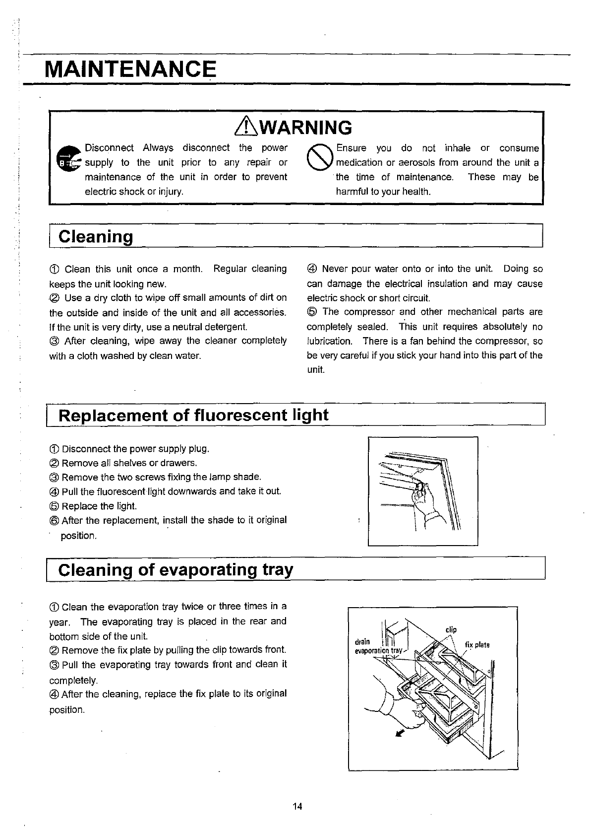
MAINTENANCE
&WARNING
..
Disconnect Always
~
supply to the unit
maintenance of the
disconnect the power
prior to any repair or
unit
in
order to prevent
electric shock or injury.
Cleaning
G) Clean this unit once a month. Regular cleaning
keeps the unit looking
new.
® Use a dry cloth
to
wipe off small amounts of dirt
on
the outside and inside of the unit
and
all accessories.
If
the unit
is
very dirty, use a neutral detergent.
® After cleaning, wipe away the cleaner completely
with a cloth washed
by
clean water.
'"
Ensure
you
do
not inhale or consume
\.y
medication or aerosols from around the unit a
. the time of maintenance. These may
be
harmful to your health.
@ Never pour water onto or into the unit. Doing
so
can
damage the electrical insulation and may cause
electric shock or short circuit.
@
The
compressor
and
other mechanical parts
are
completely sealed. This unit requires absolutely
no
lubrication. There
is
a
fan
behind the compressor,
so
be
very careful
if
you
stick your
hand
into this part of
the
unit.
Replacement
of
fluorescent light
G) Disconnect the power supply plug.
® Remove all shelves or drawers.
® Remove the two screws fixing the lamp shade.
@ Pull the fluorescent light downwards and take it
out.
@ Replace the light.
@ After the replacement, install the shade
to
it
original
position.
Cleaning
of
evaporating tray
G) Clean the evaporation tray twice or three times
in
a
year. The evaporating tray is placed
in
the rear
and
bottom side
of
the unit.
® Remove the fix plate
by
pulling the clip towards front.
®
Pull
the evaporating tray towards front
and
clean it
completely.
@ After the cleaning, replace the fix plate
to
its original
position.
14
TROUBLE SHOOTING
If
the unit malfunctions, check out the following before calling for service.
1.
If
nothing operates even when switched
on
1)
Is unit connected to the power supply?
2) Is there a power failure?
3)
Is the fuse blown.or the circuit breaker inactivated?
2. When alarm is activated
When alarm lamp and buzzer are activated, follow
procedures, to determine a cause.
1) On start-up
Does the temperature
in
the unit match set value? .
2)
In
use
Was
the door kept opened for long time? Were
containers
of
high temperature (load) put
in
the unit?
In
this case, alarm is removed automatically by running
the unit for several hours.
3.
When unit does not get cold enough
1) Is air exhaust vent blocked
up
with containers?
2)
Was
a large amount
of
warm product put
in
the
unit?
3)
Is there nearly heat source?
4) Is the door opened frequently?
5)
Is ambient temperature too high?
6) Is the unit
in
direct sunlight?
7)
8)
Is the door securely closed?
Is
the
door
seal
damaged
or
foreign
substance
inserted
between
door
gaskets?
ENVIRONMENTAL CONDITIONS
This equipment is designed to be safe at least under Ihe following conditions:
1.
Indoor use;
2.
Altitude up to 2000
m;
3.
Ambient temperature
5°C
to 40°C;
4. Maximum relative humidity 80% for temperature
up
to
31°C
decreasing linearly to 50% relative humidity at
40°C;
DISPOSAL OF UNIT
5.
Mains supply voltage fluctuations
as
stated by the
manufacturer;
6. Transient overvoltages according to Installation
Categories (Overvoltage Categoires)
II;
For mains
supply the minimum and normal category is
II;
7.
Pollution degree 2
in
accordance with IEC 664.
LtWARNING
O
When the unit is stored
in
an
unsupervised area for an extended period, ensure that children
do
not have
access and make sure the doors cannot be closed completely.
O
The disposal of the unit should be undertaken by appropriate personnel. Always remove doors to
prevent accidents such as suffocation.
15
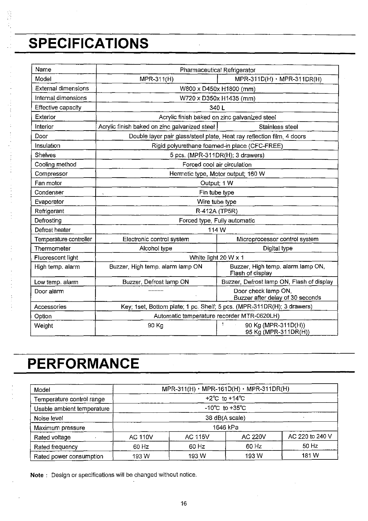
SPECIFICATIONS
Name Pharmaceutical Refrigerator
Model MPR-311(H) MPR-311 D(H) • MPR-311DR(H)
External dimensions W800 x D450x H1800 (mm)
Internal dimensions W720 x D350x H1435 (mrn)
Effective capacity 340 L
Exterior Acrylic finish baked on zinc galvanized steel
Interior Acrylic finish baked on zinc galvanized steel Stainless steel
Door Double layer pair glass/steel plate, Heat ray reflection film, 4 doors
Insulation Rigid polyurethane foamed-in place (CFC-FREE)
Shelves 5
pcs.
(MPR-311 DR(H); 3 drawers)
Cooling method Forced cool air circulation
Compressor Hermetic type, Motor output; 160 W
Fan
motor Output; 1 W
Condenser Fin tube type
Evaporator Wire tube type
Refrigerant R-412A (TP5R)
Defrosting Forced type, Fully automatic
Defrost heater 114 W
Temperature controller Electronic control system Microprocessor control system
Thermometer Alcohol type Digital type
Fluorescent light White light 20 W x 1
High temp. alarm Buzzer, High temp. alarm lamp
ON
Buzzer, High temp. alarm.lamp
ON,
Flash
of
display
Low temp. alarm Buzzer, Defrost lamp
ON
Buzzer, Defrost lamp ON, Flash
of
display
Door alarm
-----
Door check lamp ON,
Buzzer after delay
of
30 seconds
Accessories Key; 1set, Bottom plate; 1
pc.
Shelf; 5 pcs. (MPR,311DR(H); 3 drawers)
Option Automatic temperature recorder MTR-0620LH)
Weight
90
Kg
, 90
Kg
(MPR-311
D(H»
95
K~
(MPR-311DR(H))
PERFORMANCE
Model
MPR-311(H)'
MPR-161D(H) • MPR-311DR(H)
Temperature control range +2°C to +14°C
Usable ambient temperature
_10°C
to +35°C
Noise level 38 dB(A scale)
Maximum pressure 1646 kPa
Rated voltage AC 110V
AC
115V AC 220V AC 220 to 240 V
Rated frequency 60 Hz 60 Hz 60 Hz 50 Hz
Rated power consumption
193W
193 W
193W
181
W
Note:
Design
or
specifications will
be
changed without notice.
16
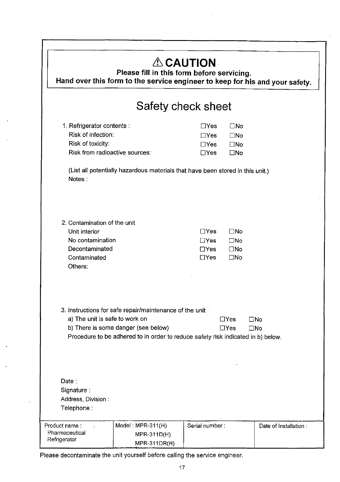
& CAUTION
Please fill
in
this form before servicing.
Hand over this form to the service engineer to keep for his
and
your safety.
Safety
check
sheet
1.
Refrigerator contents:
DYes
DNo
Risk
of
infection:
DYes
DNo
Risk
of
toxicity:
DYes
DNo
Risk from radioactive sources:
DYes
DNo
(List all potentially hazardous materials that have been stored
in
this unit.)
Notes:
2.
Contamination
of
the unit
Unit interior
DYes
DNo
No
contamination
DYes
DNo
Decontaminated
DYes
DNo
Contaminated
DYes
DNo
Others:
3.
Instructions for safe repair/maintenance of the unit
a) The unit is safe to work on
DYes
DNo
b)
There is some danger (see below)
DYes
DNo
Procedure to
be
adhered to
in
order to reduce safety risk indicated
in
b)
below.
Date:
Signature:
Address, Division:
Telephone:
Product
name:
Pharmaceutical
Refrigerator
Model:
MPR-311
(H)
MPR-311D(H)
MPR-311DR(H)
Serial number:
Please decontaminate the unit yourself before calling the service engineer.
17
Date
of Installation:
I
" i
t
'j
!
"-j
'I
7FB6P10124000
SANYO Electric Co., Ltd.
Refrigerating Products Division
1-1-1, Sakata Oizumi-Machi,
Ora-Gun, Gunma 370-0596 Japan
Printed
in
Japan
