Sanyo Vsp 3000 Users Manual 00GB_L8CSE_WA_Hyoshi_all
VSP-3000 to the manual e72d6b84-f929-45e0-b27c-ca03a5652ac9
2015-01-26
: Sanyo Sanyo-Vsp-3000-Users-Manual-338403 sanyo-vsp-3000-users-manual-338403 sanyo pdf
Open the PDF directly: View PDF ![]() .
.
Page Count: 34
INSTRUCTION MANUAL
System Controller
VSP-3000
About this manual
• Before installing and using this unit, please read this manual carefully. Be sure to keep it handy for
later reference.
01GB_L8CSE_WA_VSP3000.indd 101GB_L8CSE_WA_VSP3000.indd 1 2008/02/29 13:16:552008/02/29 13:16:55
Introduction
1
Introduction
Precautions ........................................................ 2
Safety Cautions ................................................. 3
Main features ..................................................... 7
Accessories ....................................................... 7
Preparations
Part names ......................................................... 8
Connection method ......................................... 10
Connecting to a Sanyo camera .................. 10
Connecting to a Sanyo DVR ...................... 11
Connecting to a Sanyo DVR
with a mouse function ................................ 12
Menu settings .................................................. 13
Main menu steps ........................................ 13
Language setting .................................. 14
Title setting ........................................... 14
List of title input characters ................... 14
Control ID setting .................................. 15
Termination setting ................................ 15
Sleep setting ......................................... 16
Buzzer setting ....................................... 16
Backlight setting .................................... 17
Mouse setting ....................................... 17
DVR link setting .................................... 18
Password setting ................................... 18
Default setting ....................................... 19
Camera settings ............................................... 20
Camera setup steps ................................... 20
Address setting ..................................... 21
Protocol setting ..................................... 21
Baud rate setting ................................... 22
Pan and tilt speed setting ...................... 22
DVR address and channel setting ........ 23
■
■
■
■
■
Operation
Camera operations .......................................... 24
Operating the camera from the system
controller .................................................... 24
Camera operation buttons ......................... 24
Operating the camera by changing
camera menu settings using the system
controller .................................................... 25
Auxiliary function operation ........................ 26
Preset position retrieval operation ............. 26
Preset memory operations ......................... 26
Retrieving pan, sequence and tour
operations recorded in a PTZ camera ....... 27
DVR operation .................................................. 28
Switching the DVR screen display ............. 28
Operating a DVR with mouse function .......... 29
Others
Appendices ...................................................... 30
List of auxiliary commands for Sanyo
cameras ..................................................... 30
Camera address numbers (default value)
... 31
Specifications .................................................. 32
External dimensions .................................. 32
■
■
■
■
■
■
■
■
■
■
■
Contents
SERVICE
This unit is a precision instruments and if treated
with care, will provide years of satisfactory
performance. However, in the event of a problem,
the owner is advised not to attempt to make
repairs or open the cabinet. Servicing should
always be referred to your dealer or Sanyo
Authorized Service Center.
01GB_L8CSE_WA_VSP3000.indd 101GB_L8CSE_WA_VSP3000.indd 1 2008/02/29 13:16:552008/02/29 13:16:55
Introduction 2
Precautions
For UL Users
CAUTION
RISK OF ELECTRIC SHOCK
DO NOT OPEN
CAUTION: TO REDUCE THE RISK OF
ELECTRIC SHOCK, DO NOT REMOVE COVER
(OR BACK).
NO USER-SERVICEABLE PARTS INSIDE.
REFER SERVICING TO QUALIFIED SERVICE
PERSONNEL.
WARNING: To reduce the risk of fire or
electric shock, do not expose this appliance to
rain or moisture.
The lightning flash with arrowhead
symbol, within an equilateral triangle,
is intended to alert the user to the
presence of uninsulated “dangerous
voltage” within the product’s enclosure
that may be of sufficient magnitude to
constitute a risk of electric shock to
persons.
The exclamation point within an
equilateral triangle is intended to
alert the user to the presence of
important operating and maintenance
(servicing) instructions in the literature
accompanying the product.
CAUTION: Changes or modifications not
expressly approved by the manufacturer may void
the user’s authority to operate this equipment.
This equipment has been tested and found to
comply with the limits for a Class B digital device,
pursuant to part 15 of the FCC Rules. These limits
are designed to provide reasonable protection
against harmful interference in a residential
installation. This equipment generated, uses
and can radiate radio frequency energy and, if
not installed and used in accordance with the
instructions, may cause harmful interference
to radio communications. However, there is no
guarantee that interference will not occur in a
particular installation. If this equipment does
cause harmful interference radio or television
reception, which can be determined by turning the
equipment off and on, the user is encouraged to
try to correct the interference by one or more of
the following measures:
Reorient or relocate the receiving antenna.
■
•
Increase the separation between the equipment
and receiver.
Connect the equipment into an outlet on a
circuit different from that to which the receiver is
connected.
Consult the dealer or an experienced radio/TV
technician for help.
For the customers in Canada
This class B digital apparatus complies with
Canadian ICES-003.
For EU Users
Please note:
Your SANYO product is designed
and manufactured with high quality
materials and components which
can be recycled and reused.
This symbol means that electrical
and electronic equipment, at their
end-of-life, should be disposed of
separately from your household
waste.
Please dispose of this equipment
at your local community waste
collection/recycling centre.
In the European Union there are
separate collection systems for
used electrical and electronic
products.
Please help us to conserve the
environment we live in!
This symbol mark and recycle
system are applied only to EU
countries and not applied to
the countries in the other area
of the world.
SANYO FISHER Sales (Europe) GmbH
Stahlgruberring 4, D-81829 München, Germany
SANYO Electric Co., Ltd.
1-1, Sanyo-cho, Daito City, Osaka 574-8534,
Japan
For Russian Users
This product certified by official
certification company which is
authorized by Russian Federation.
ДЛЯ ПОЛЬЗОВАТЕЛЕЙ РОССИЯ
Данная продукция
сертифицирована официальным
органом по сертификации
Российской Федерации.
•
•
•
■
■
■
01GB_L8CSE_WA_VSP3000.indd 201GB_L8CSE_WA_VSP3000.indd 2 2008/02/29 13:16:562008/02/29 13:16:56

Introduction
3
WARNING
Never use when unit emits smoke,
unusual noises, or unusual smells.
Using under these abnormal conditions can
cause fires and electric shock.
Immediately unplug the AC adapter power plug
from the outlet, confirm that the smoke stops,
and then request repairs from the installer or the
purchasing source.
Never attempt to repair the unit on your own, as
this is dangerous.
Never disassemble or modify
Touching the internal parts is dangerous, and
can cause fires and electric shock.
Request internal inspection, adjustment, and
repairs from the installer or the location of
purchase.
Never get unit wet
This unit is not waterproof or dustproof. Do
not install where exposed to rain, excessive
humidity, or excessive dust. This can cause
fires and electric shock.
Do not install in a bath or shower room.
In the event that water enters the unit interior,
unplug the AC adapter power plug from the
outlet, and contact the installer or location
of purchase. Continued use can cause fires,
electric shock, and unit breakdowns.
Do not use during thunderstorms
Do not use this during thunderstorms.
In particular, never touch the AC adapter or
connection cables. This can cause electric shock.
■
■
•
•
■
•
•
■
Do not install in unstable location
The unit may fall or topple, causing injuries or
unit breakdowns.
In the event that the unit is dropped or the
cabinet is broken, unplug the AC adapter
power plug from the outlet, and contact the
installer or location of purchase.
Continued use can cause fires or electric
shock.
Do not use in locations with explosion
risk
Do not use in locations where flammable gas or
explosive gas may exist in the atmosphere. This
can cause ignition and explosion.
Fogging (Condensation)
Drops of water form on the outside of a glass
containing very cold water. Similarly, droplets
can form on the interior of this unit. This is
called fogging, or condensation.
Using the unit during fogging can cause a unit
breakdown.
Be careful of fogging when the environment
temperature changes suddenly, such as when
heating the room quickly.
Fogging does not occur while electrical current
is present.
When fogging could occur...
Turn OFF the unit power, and leave the unit
in its installed position for one to two hours
before use.
■
•
•
■
Main Unit
Safety Cautions
01GB_L8CSE_WA_VSP3000.indd 301GB_L8CSE_WA_VSP3000.indd 3 2008/02/29 13:16:572008/02/29 13:16:57
Introduction 4
CAUTION
Transport with care
Unplug the AC adapter power plug from the
outlet, confirm that connection cables are
disconnected, and transport carefully to avoid
dropping the unit or subjecting it to severe shock.
Cautions for care or long-term disuse
Unplug the AC adapter power plug from the
outlet. Caring for the unit with the AC adapter
connected can cause electric shock.
Cleaning the interior
For cleaning the interior, consult the installer
or the location of purchase. When dust
has accumulated inside the unit over time
without cleaning, this can cause fires or unit
breakdowns.
Installation location
This unit is comprised of precision electronic
parts. Never install in the locations described
below, as this can cause operation errors and
unit breakdowns.
In direct sunlight
In extreme humidity or where humidity
fluctuates wildly
Where water could be splashed
Near heating/cooling equipment or humidifiers.
Where cold air from air conditioners contact the
unit directly
Where dust is extreme
Near a spark source
Near magnetic objects
Near explosive materials
Where subject to vibration
■
■
■
■
•
•
•
•
•
•
•
•
•
•
DANGER
Only use with 100 to 240V power source
voltage.
This can cause fires and electric shock.
Never disassemble or modify
Touching the internal parts is dangerous, and
can cause fires and electric shock.
Never use as a DC power source unit.
Never get unit wet
Never submerge in water or get unit wet. This
can cause fires and electric shock.
Do not use in a bath or shower room.
In the event that water enters the unit interior,
unplug the power plug from the outlet, and
contact the installer or location of purchase.
Continued use can cause fires, electric shock,
and unit breakdowns.
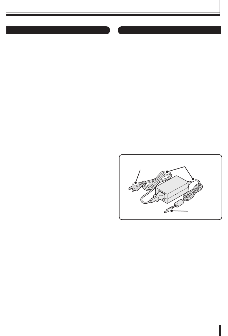
DC plug
Power cord
Power plug
AC adapter
■
■
•
•
■
•
•
•
Safety Cautions
Provided AC Adapter
01GB_L8CSE_WA_VSP3000.indd 401GB_L8CSE_WA_VSP3000.indd 4 2008/02/29 13:16:572008/02/29 13:16:57

Introduction
5
Provided AC Adapter
WARNING
Use only the provided AC adapter
Use the provided AC adapter. Using a different
AC adapter can cause fires or electric shock,
due to differences in power cord current capacity.
Never touch the AC adapter with wet
hands
This can cause electric shock.
Power cord
Never bundle up the power cord during use. This
can cause overheating, fires and electric shock.
When using an extension cord
Be careful that the total power consumption of
the connected equipment does not exceed the
rated power of the extension cord.
Exceeding the rated power can cause fires.
■
■
■
■
Power plug
Never use while abnormality is not corrected.
The following situations can cause fires or
electric shock.
Never allow dust to accumulate on power plug
or in outlet insertion holes. Dust and dirt on
either contact portion can cause an electric
short or overheating. Wipe off with a dry cloth.
When using an outlet where humidity is high
or condensation forms easily, or an outlet in
a kitchen or dusty environment, unplug the
power plug regularly and wipe off the dust and
dirt adhering to the plug.
Never pull the power cord to unplug the power
plug.
Always hold the power plug when unplugging.
Never leave the power plug plugged into the
outlet while the DC plug is disconnected from
the power source input terminal on this unit.
This can cause electric shock when touching
with wet hands, or when an infant places the
power plug in his/her mouth.
Never use an outlet if the power plug is fully
seated but is still loose in the outlet. This can
cause fires due to overheating.
Never use the power plug when it is damaged.
When the plug has poor contact, consult the
installer or the location of purchase.
■
•
•
•
•
•
•
Safety Cautions (Continued)
01GB_L8CSE_WA_VSP3000.indd 501GB_L8CSE_WA_VSP3000.indd 5 2008/02/29 13:16:572008/02/29 13:16:57

Introduction 6
Safety Cautions
CAUTION
Do not connect to other equipment
The provided AC adapter and power cable are
exclusively for use with this unit. Connecting
to other equipment can cause fires or electric
shock.
Power cord
Damaging the power cord in the following
manner can cause fires or electric shock.
When the power cord is damaged, consult the
installer or the location of purchase.
Never place a heavy object on the power
cord, or expose to heating equipment, heated
surfaces (front surface of heaters), or direct
sunlight.
Do not stress the power cord with the weight of
the AC adapter unit.
Never bundle up the power cord during use.
Never bend, modify, or staple the power cord.
Power cord connection
Route the power cord and connecting cables
with care. Tripping over power cords can cause
injuries due to falls or falling equipment.
Connect power plug securely to outlet
Using with an incomplete connection can cause
fires due to overheating.
Do not place in unstable location
Place the unit in a stable location.
Placing the unit in an unstable location can
cause injuries or unit breakdowns, due to falling
or toppling equipment.
■
■
•
•
•
•
■
■
■
Always Observe These
Rules for Proper Use
Caring for the Unit
Unplug the power plug from the outlet.
Gently wipe away any contamination, using a
soft cloth.
When heavily soiled...
Immerse a cloth in neutral detergent thinned
with water, wring it well, and wipe the unit.
Finish with a dry cloth.
Cautions
Never use benzene or paint thinner to clean the
unit. The unit could discolor, or paint could be
removed.
When using chemically treated cloths, note the
cautions on the package.
Do not expose the unit to volatile chemicals such
as pesticides. Do not leave the unit in contact with
rubber or plastic products for long periods.
The unit could discolor, or paint could be
removed.
When not using for long periods
Unplug the power plug from the outlet.
However, this could damage the functions.
Connect the power and operate the unit
occasionally.
■
•
•
•
■
01GB_L8CSE_WA_VSP3000.indd 601GB_L8CSE_WA_VSP3000.indd 6 2008/02/29 13:16:582008/02/29 13:16:58
Introduction
7
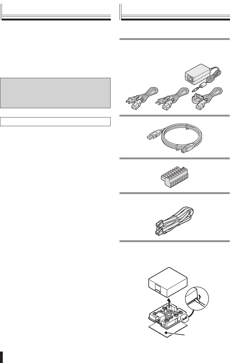
Main features Accessories
You can use the joystick to carry out
pan, tilt and zoom operations for the
camera.
RS-485 communication cable can be
connected.
Password setting is available.
Trademark
Brands and product names described in
this document are trademarks or registered
trademarks of their respective companies.
Licensed Under U.S. Patent No. 4974088
•
•
•
Check that all accessories are included.
AC adapter/power cord x 3
North America: 1
Europe: 1
Great Britain: 1
•
•
•
USB cable
Connector
Modular cable
(Straight type: 3 m)
Communication conversion connector
Double-faced tape
Double-faced
tape
(How to disassemble)
•
•
01GB_L8CSE_WA_VSP3000.indd 701GB_L8CSE_WA_VSP3000.indd 7 2008/02/29 13:16:582008/02/29 13:16:58
Preparations 8
①
④ ⑥⑤ ⑧⑨
② ③
PWR Tx Rx
⑩
⑦
DVR: Digital video recorder
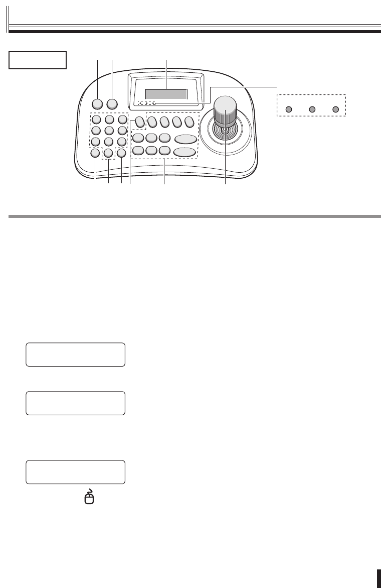
① Escape/Power button (ESC/PWR)
ESC:
This is used to exit from the current operating
menu and return to the initial screen.
PWR:
When you press the button, the power turns
on and the PWR indicator on the power/
communication indicator panel illuminates.
The version information will be displayed in the
menu display, and then the initial screen will be
displayed.
(Version information)
SANYO VSP-3000
Ver:X.XX
▼
•
(Initial screen)
SANYO SSP 19.2k
CAM:001 D1 CH01
If you press and hold the button for
approximately 3 seconds, “POWER OFF” will
be displayed. When you release the button, the
power will turn off.
SANYO SSP 19.2k
< POWER OFF >
② Mouse button ( )
If the accessory USB cable is used to connect
a DVR with a mouse function (sold separately)
to the USB mouse port at the rear of the system
controller, the joystick can be used to operate the
cursor. (P29)
•
③ Menu display
This displays the information which is required for
menu settings.
④ Clear button (CLR)
This button is used to correct any character input
errors such as passwords.
⑤ Numeric buttons (0 to 9)
These are used to select camera numbers and for
character input.
⑥ Enter button (ENT)
This is used to confirm menu settings.
⑦ DVR operation button (P28)
⑧ Camera operation buttons
These are used to operate the cameras. (P20)
⑨ Joystick
This controls the pan (left and right), tilt (forward
and back) and zoom in and out (rotation)
operations of the camera. In addition, it is used
to select menu items which are appearing in the
menu display.
⑩ Power/communication indicator panel
PWR (Power): Illuminates when the power is
turned on.
Tx: Flashes while a command is being sent.
Rx: Flashes while a command is being received.
•
•
•
Front
Part names
01GB_L8CSE_WA_VSP3000.indd 801GB_L8CSE_WA_VSP3000.indd 8 2008/02/29 13:16:582008/02/29 13:16:58
Preparations
9
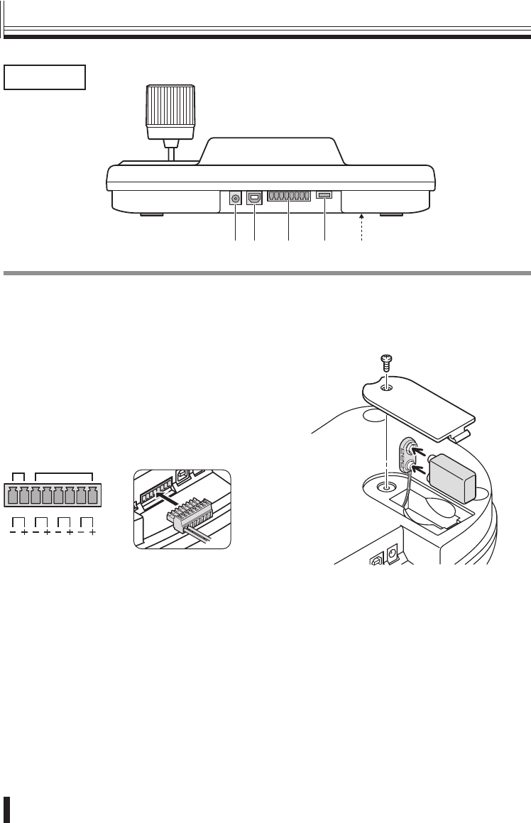
① ② ③ ④ ⑤
① Power terminal (DC 12 V)
Connect the accessory AC adapter to the DC
terminal.
② USB mouse port (USB)
Connect the accessory USB cable to this port if
using a DVR with a mouse function.
③ RS-485/RS-422 communication
terminals (TRx, Tx3, Tx2, Tx1)
When operating a camera or DVR, connect the
cable from that device to the accessory connector,
and then insert the connector into these terminals.
TRx Tx3 Tx2 Tx1
*1 *2
*1 For Sanyo SSP connections (TRx)
+: RS485A
−: RS485B
If the DVR uses only an RJ11 terminal,
use the accessory modular cable and the
conversion connector. (P11)
*2 For PELCO-D/HSSP connections (Tx3 to
Tx1)
+: RS485A
−: RS485B
④ Program terminal (PROGRAM)
This is for service use.
⑤ Battery compartment (DC 9 V)
Use commercially-available alkaline battery.
Rear
Part names (continued)
01GB_L8CSE_WA_VSP3000.indd 901GB_L8CSE_WA_VSP3000.indd 9 2008/02/29 13:16:592008/02/29 13:16:59
Preparations 10
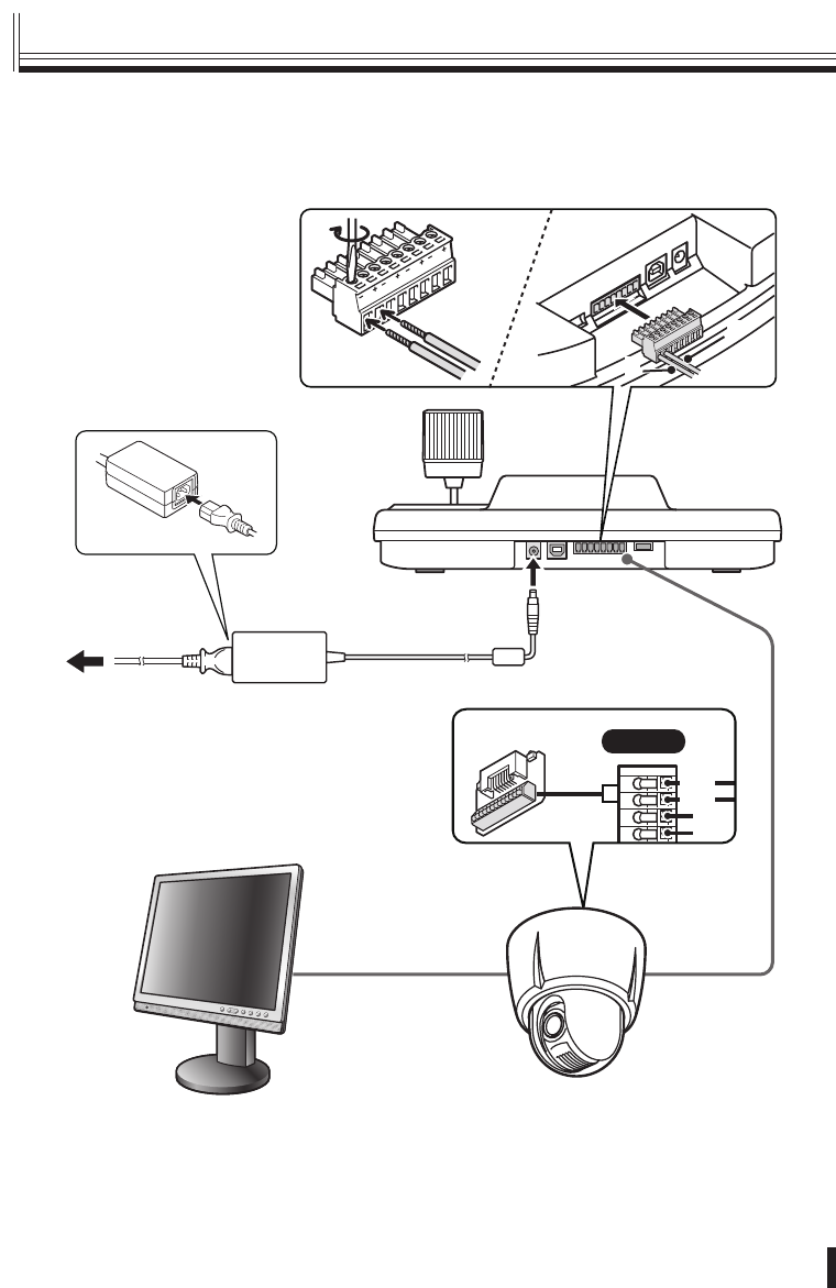
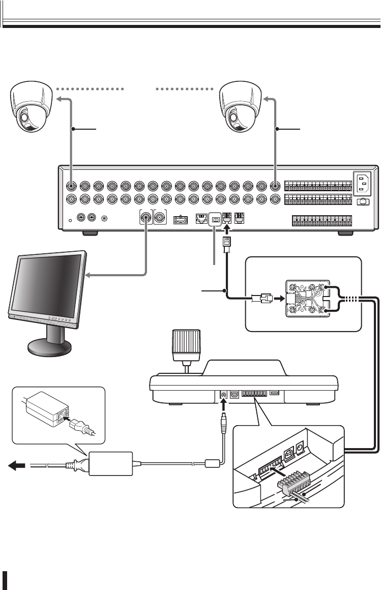
Connecting to a Sanyo camera (Operation: P20)
Monitor (sold separately)
AC adapter (accessory)
485A
485B
SIDE-A
Dome camera (sold separately)
TRx (+) : A
TRx (–) : B
A
B
Tx1
Tx2
Tx3
TRx
System
controller
■
Connection method
01GB_L8CSE_WA_VSP3000.indd 1001GB_L8CSE_WA_VSP3000.indd 10 2008/02/29 13:16:592008/02/29 13:16:59
Preparations
11
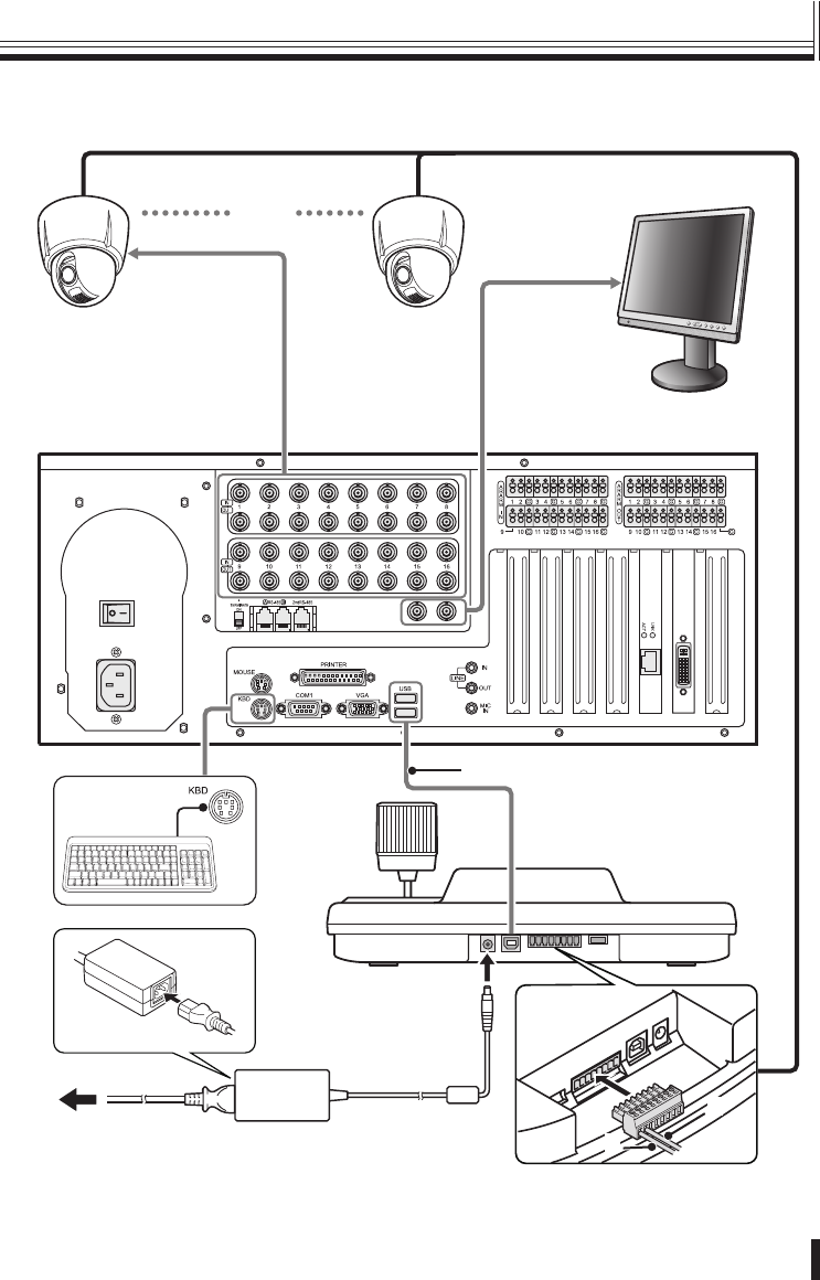
Connecting to a Sanyo DVR (Operation: P28)
Set the protocol to “SSP” for all of the cameras being connected. (Protocol setting: P21)
A RS-485 B
DO NOT CONNECT TO PHONE LINE
1
IN
OUT MONITOR OUT
MON2
2 3 4 5 6 7 8 9 10 11 12 13 14 15 16
MAIN
Camera
(sold separately)
Camera
(sold separately)
Video input terminal Video input terminal
Digital video recorder (sold separately)
Video input
terminal
Termination switch
System controller
Monitor
(sold separately)
WH
B
L
S
L
O
R
B
R
B
K
Y
L
R
D
G
R
Red
Green
Coaxial cable Coaxial cable
Conversion connector
(accessory)
TRx (+) : A (Green)
TRx (–) : B (Red)
A
B
Modular cable
(accessory)
(1−16)
AC adapter (accessory)
■
Connection method (continued)
01GB_L8CSE_WA_VSP3000.indd 1101GB_L8CSE_WA_VSP3000.indd 11 2008/02/29 13:17:002008/02/29 13:17:00
Preparations 12
Connection method
Connecting to a Sanyo DVR with a mouse function (Operation: P29)
T
Camera
(sold separately)
Camera
(sold separately)
Video input
terminal
DVR with mouse function
(sold separately)
Video input
terminal
System controller
Monitor
(sold separately)
(1−16)
A
B
TRx (+) : A
TRx (–) : B
USB cable (accessory)
AC adapter (accessory)
■
01GB_L8CSE_WA_VSP3000.indd 1201GB_L8CSE_WA_VSP3000.indd 12 2008/02/29 13:17:012008/02/29 13:17:01
Preparations
13
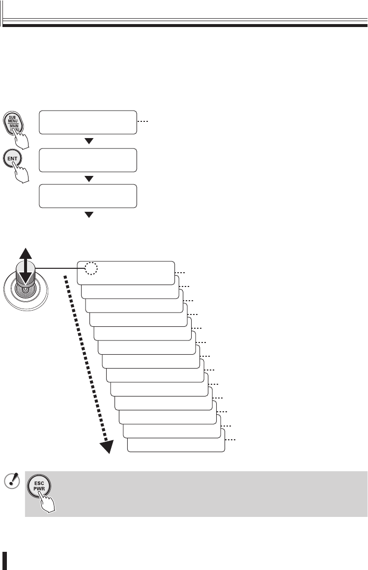
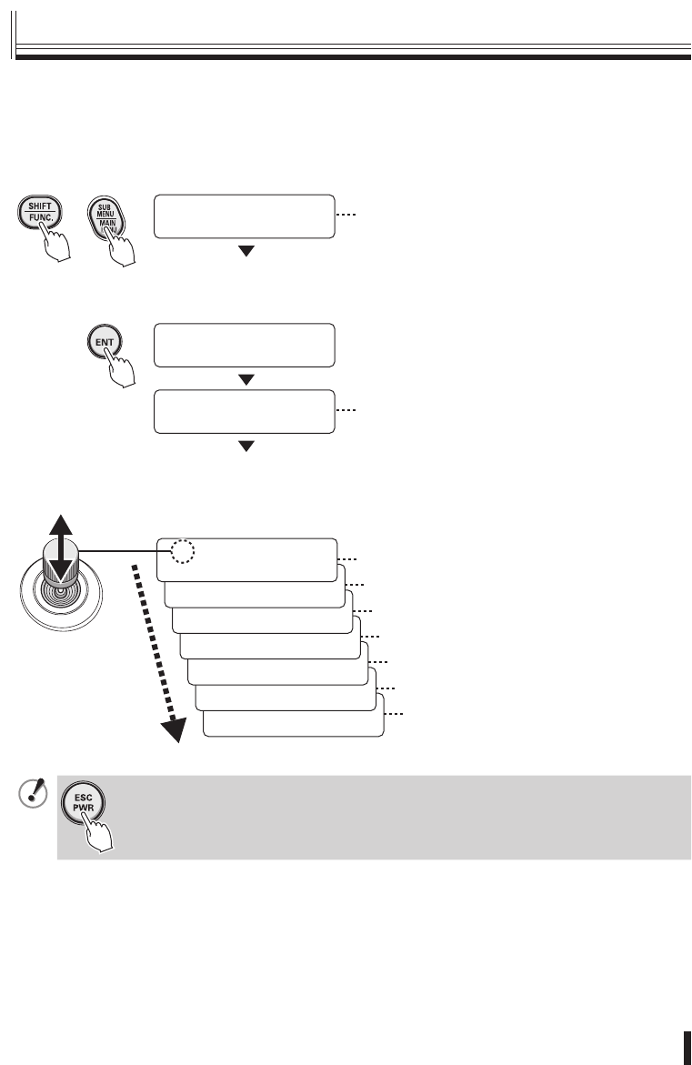
Main menu steps
Press the SUB MENU/MAIN MENU button.
The MAIN MENU screen appears in the menu display and you are prompted to enter the
password. No password is set initially, so simply press the ENT button. “1.VER: X.XX” will
then be displayed.
[ MAIN MENU ]
PASSWORD[ ---- ]
[ MAIN MENU ]
OK
[ñ MAIN MENU ]
1.VER: X.XX
To set a password, refer to “À Password setting”
in the menu setting section. (P18)
[ó
ñ MAIN MENU ]
14.SAVE/EXIT · Saving and returning to the initial
screen
[ó
ñ MAIN MENU ]
13.FACTORY SET · Á Default setting P19
[ó
ñ MAIN MENU ]
12.PASSWORD:**** À Password setting P18
[ó
ñ MAIN MENU ]
11.DVR LINK: ON 9 DVR link setting P18
[ó
ñ MAIN MENU ]
10.MOUSE SET:OFF 8 Mouse setting P17
[ó
ñ MAIN MENU ]
9.BACKLIGHT:OFF 7 Backlight setting P17
[ó
ñ MAIN MENU ]
8.BUZZER: OFF 6 Buzzer setting P16
[ó
ñ MAIN MENU ]
7.SLEEP: OFF 5 Sleep setting P16
[ó
ñ MAIN MENU ]
6.TERMINATE: ON 4 Termination setting P15
[ó
ñ MAIN MENU ]
5.CONTROL ID: 0 3 Control ID setting P15
[ó
ñ MAIN MENU ]
4.TITLE SET · 2 Title setting P14
[ó
ñ MAIN MENU ]
3.LANGUAGE SET · 1 Language setting (English only) P14
Use the joystick to switch menu displays.
To save the menu settings, select “YES” in “14. SAVE/EXIT”.
[ó
ñ MAIN MENU ]
2.DATE:DEC.03
This is the firmware information. It cannot be
changed.
To cancel any changes you have made while carrying out menu settings, press
the ESC/PWR button. The display will return to the initial screen. Any menu
settings which you have changed will not be saved.
■
Menu settings
01GB_L8CSE_WA_VSP3000.indd 1301GB_L8CSE_WA_VSP3000.indd 13 2008/02/29 13:17:022008/02/29 13:17:02
Preparations 14
Menu settings
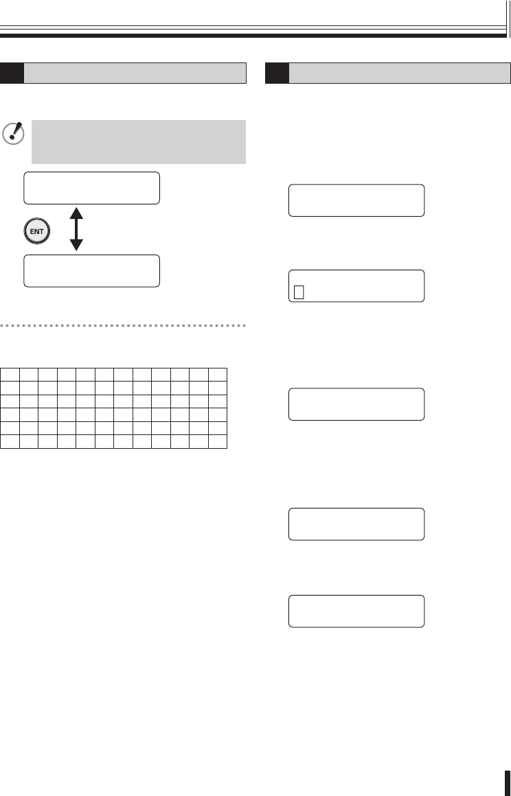
1Language setting
The only available language for menus is English.
No setting is neccessary.
When “ENGLISH” is displayed, press
the ENT button or the ESC/PWR button
to return to the MAIN MENU screen.
[ó
ñ MAIN MENU ]
3.LANGUAGE SET ·
[ LANGUAGE SET†]
ENGLISH
List of title input characters
[¥]ˆ
■
!"#$%&'
()*+,-./0123
456789:·<=>?
ABCDEFGHIJK
LMNOPQRSTUVW
XYZ
2Title setting
This sets a title (maximum 16 characters) for the
system controller.
(Default setting: VSP-3000 ➝ Example: SAN
1001)
1Move the joystick up or down to
select “4. TITLE SET”.
[ó
ñ MAIN MENU ]
4.TITLE SET ·
2Move the joystick to the right.
“TITLE SET” will be displayed and the first
character “V” will flash.
[ TITLE SET ]
VSP-3000
3Move the joystick up or down to
select a character, and then move the
joystick to the right to select the next
character.
Repeat these steps to enter the title.
[ TITLE SET ]
SAN 1001
4Press the ENT button.
The display will return to “4. TITLE SET”.
5Move the joystick up or down to
select “14. SAVE/EXIT”, and then
move the joystick to the right.
[ó MAIN MENU ]
14.SAVE/EXIT ·
6Move the joystick to the left or right
to select “YES”, and then press the
ENT button.
[ SAVE / EXIT ]
NO <YES>
The setting will be saved and the display will
return to the initial screen.
01GB_L8CSE_WA_VSP3000.indd 1401GB_L8CSE_WA_VSP3000.indd 14 2008/02/29 13:17:022008/02/29 13:17:02
Preparations
15
3Control ID setting
If using more than one system controller, change
the addresses for each of them. The addresses
can be assigned to a number within the range of
0 to 4.
(Default setting: 0)
1Move the joystick up or down to
select “5. CONTROL ID”.
[ó
ñ MAIN MENU †]
5.CONTROL ID: 0
2Move the joystick to the left or right
to assign the address (Example: 3).
[ó
ñ MAIN MENU †]
5.CONTROL ID: 3
Available settings: 0−4
3Move the joystick up or down to
select “14. SAVE/EXIT”, and then
move the joystick to the right.
[ó MAIN MENU ]
14.SAVE/EXIT ·
4Move the joystick to the left or right
to select “YES”, and then press the
ENT button.
[ SAVE / EXIT ]
NO <YES>
The setting will be saved and the display will
return to the initial screen.
4Termination setting
Set the termination for the system controller.
(Default setting: ON)
1Move the joystick up or down to
select “6. TERMINATE”.
2Move the joystick to the left or right
to set the termination.
[ó
ñ MAIN MENU í]
6.TERMINATE: ON
3Move the joystick up or down to
select “14. SAVE/EXIT”, and then
move the joystick to the right.
[ó MAIN MENU ]
14.SAVE/EXIT ·
4Move the joystick to the left or right
to select “YES”, and then press the
ENT button.
[ SAVE / EXIT ]
NO <YES>
The setting will be saved and the display will
return to the initial screen.
Menu settings (continued)
01GB_L8CSE_WA_VSP3000.indd 1501GB_L8CSE_WA_VSP3000.indd 15 2008/02/29 13:17:032008/02/29 13:17:03
Preparations 16
Menu settings
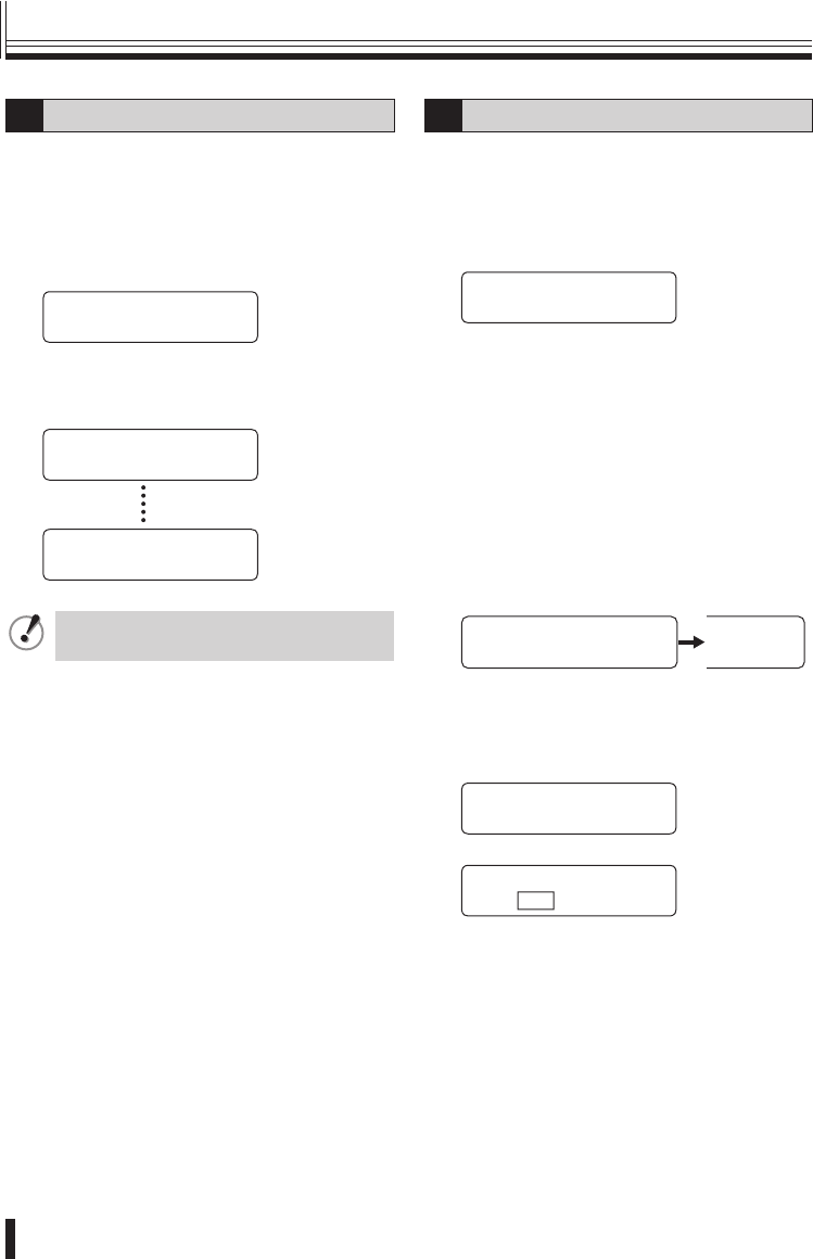
5Sleep setting
You can set the system controller to turn off
automatically if it is not operated for a certain
period of time. When this is done, a moving
“SLEEP MODE” display will appear in the menu
display.
(Default setting: OFF)
1Move the joystick up or down to
select “7. SLEEP”.
[ó
ñ MAIN MENU †]
7.SLEEP: OFF
2Move the joystick to the left or
right to select the time (Example: 1
(HOUR)).
[ó
ñ MAIN MENU í]
7.SLEEP: 1(HOUR)
Available settings:
OFF, 1(MIN), 5(MIN), 10(MIN), 30(MIN),
1(HOUR)
3Move the joystick up or down to
select “14. SAVE/EXIT”, and then
move the joystick to the right.
[ó MAIN MENU ]
14.SAVE/EXIT ·
4Move the joystick to the left or right
to select “YES”, and then press the
ENT button.
[ SAVE / EXIT ]
NO <YES>
The setting will be saved and the display will
return to the initial screen.
When the specified sleep mode is reached,
the following display will appear.
VSP-3000
SLEEP MODE
6Buzzer setting
This sets the buzzer when the system controller is
operated.
(Default setting: OFF)
1Move the joystick up or down to
select “8. BUZZER”.
[ó
ñ MAIN MENU †]
8.BUZZER: OFF
2Move the joystick to the left or right
to set the buzzer (Example: ON).
[ó
ñ MAIN MENU í]
8.BUZZER: ON
Available settings: ON, OFF
3Move the joystick up or down to
select “14. SAVE/EXIT”, and then
move the joystick to the right.
[ó MAIN MENU ]
14.SAVE/EXIT ·
4Move the joystick to the left or right
to select “YES”, and then press the
ENT button.
[ SAVE / EXIT ]
NO <YES>
The setting will be saved and the display will
return to the initial screen.
01GB_L8CSE_WA_VSP3000.indd 1601GB_L8CSE_WA_VSP3000.indd 16 2008/02/29 13:17:032008/02/29 13:17:03
Preparations
17
7Backlight setting
This sets the brightness of the system controller’s
menu display screen.
(Default setting: OFF)
1Move the joystick up or down to
select “9. BACKLIGHT”.
[ó
ñ MAIN MENU †]
9.BACKLIGHT:OFF
2Move the joystick to the left or right
to set the backlight (Example: AUTO).
[ó
ñ MAIN MENU í]
9.BACKLIGHT:AUTO
Available settings:
OFF: Never illuminated
ON: Always illuminated
AUTO: Illuminates only while the system
controller is being operated, and
switches off after approximately
30 seconds.
3Move the joystick up or down to
select “14. SAVE/EXIT”, and then
move the joystick to the right.
[ó MAIN MENU ]
14.SAVE/EXIT ·
4Move the joystick to the left or right
to select “YES”, and then press the
ENT button.
[ SAVE / EXIT ]
NO <YES>
The setting will be saved and the display will
return to the initial screen.
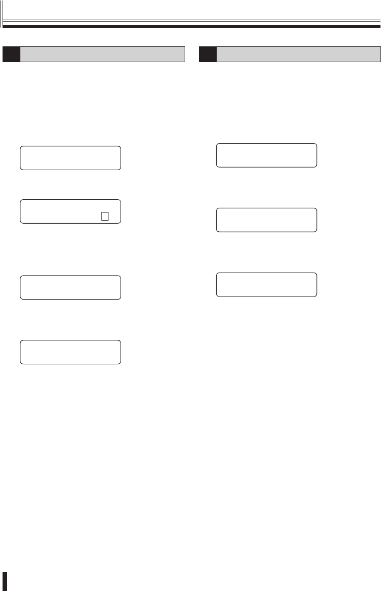
8Mouse setting
Use this setting when operating a DVR with a
mouse function. To use the mouse function,
change the setting to a setting other than “OFF”.
Refer to P12 for details on the connection method.
(Default setting: OFF)
1Move the joystick up or down to
select “10. MOUSE SET”
[ó
ñ MAIN MENU †]
10.MOUSE SET:OFF
2Move the joystick to the left or right
to set the cursor movement speed
(Example: LOW).
[ó
ñ MAIN MENU †]
10.MOUSE SET:LOW
Available settings: OFF, LOW, MID, HIG
3Move the joystick up or down to
select “14. SAVE/EXIT”, and then
move the joystick to the right.
[ó MAIN MENU ]
14.SAVE/EXIT ·
4Move the joystick to the left or right
to select “YES”, and then press the
ENT button.
[ SAVE / EXIT ]
NO <YES>
The setting will be saved and the display will
return to the initial screen.
Refer to P29 for details on operating a DVR
with mouse function.
Menu settings (continued)
01GB_L8CSE_WA_VSP3000.indd 1701GB_L8CSE_WA_VSP3000.indd 17 2008/02/29 13:17:042008/02/29 13:17:04
Preparations 18
Menu settings
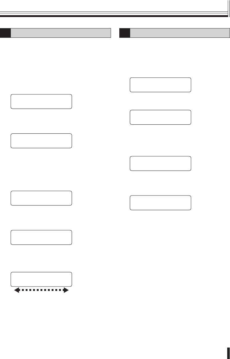
9DVR link setting
The camera images from the DVR which is
connected to the system controller switch in line
with the camera selection.
(Default setting: ON)
1Move the joystick up or down to
select “11. DVR LINK”.
[ó
ñ MAIN MENU í]
11.DVR LINK: ON
2Move the joystick to the left or right
to set the DVR connection (Example:
OFF).
[ó
ñ MAIN MENU †]
11.DVR LINK: OFF
Available settings: ON, OFF
3Move the joystick up or down to
select “14. SAVE/EXIT”, and then
move the joystick to the right.
[ó MAIN MENU ]
14.SAVE/EXIT ·
4Move the joystick to the left or right
to select “YES”, and then press the
ENT button.
[ SAVE / EXIT ]
NO <YES>
The setting will be saved and the display will
return to the initial screen.
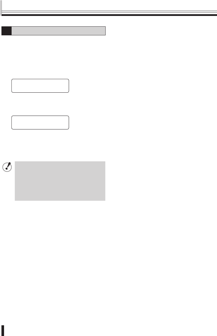
10 Password setting
You can change the password for the system
controller.
(Default setting: No password)
1Move the joystick up or down to
select “12. PASSWORD”.
[ó
ñ MAIN MENU ]
12.PASSWORD:****
2Use the numeric buttons to enter a
password (Example: 1234) and then
press the ENT button.
The password entered will be displayed for
approximately 1 second, and then the display
will return to the password setting screen.
[ó
ñ MAIN MENU ]
12.PASSWORD:1234
▼
[ó
ñ MAIN MENU ]
12.PASSWORD:****
3Move the joystick up or down to
select “14. SAVE/EXIT”, and then
move the joystick to the right.
[ó MAIN MENU ]
14.SAVE/EXIT ·
4Move the joystick to the left or right
to select “YES”, and then press the
ENT button.
[ SAVE / EXIT ]
NO <YES>
The setting will be saved and the display will
return to the initial screen.
01GB_L8CSE_WA_VSP3000.indd 1801GB_L8CSE_WA_VSP3000.indd 18 2008/02/29 13:17:042008/02/29 13:17:04
Preparations
19
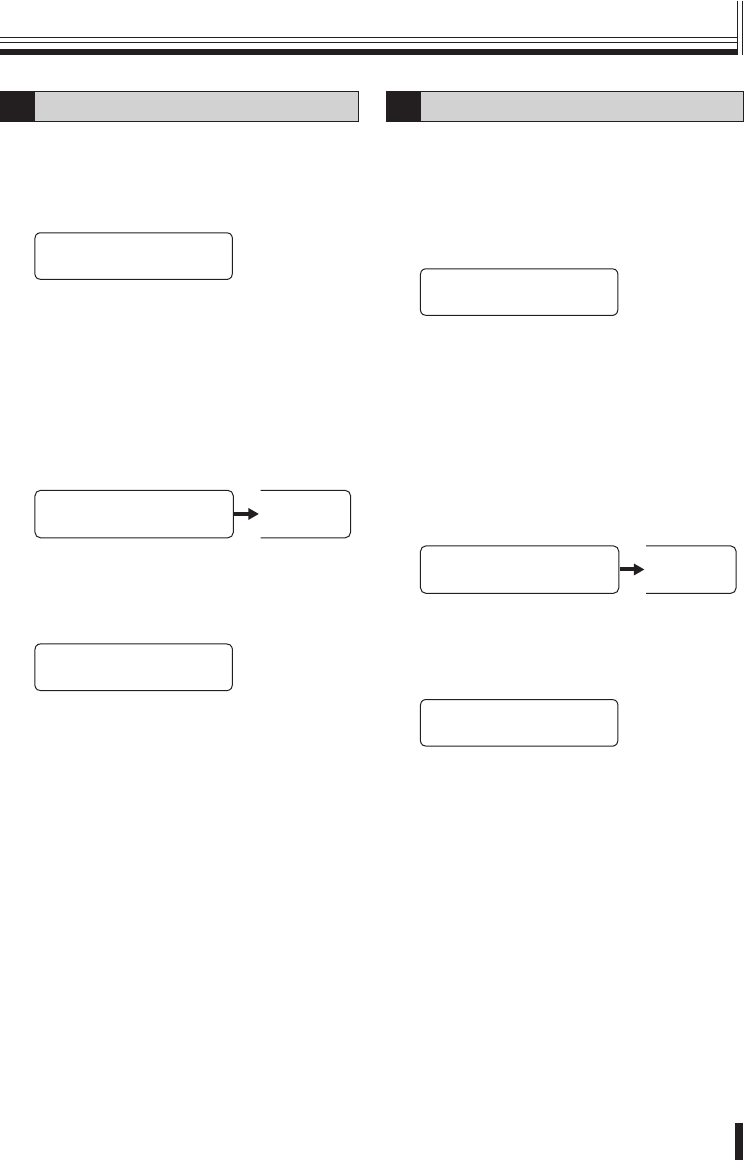
11 Default setting
This returns all settings to the default settings that
were in place at the time of shipment from the
factory.
1Move the joystick up or down to
select “13. FACTORY SET”, and then
move the joystick to the right.
[ó
ñ MAIN MENU ]
13.FACTORY SET ·
2Move the joystick to the left or right
to select “YES”, and then press the
ENT button.
[ FACTORY SET ]
NO <YES>
Available settings: NO, YES
Once the default settings have all been set,
the display will return automatically to the
initial screen.
When returning all settings to the
default settings, the camera settings
and all setting contents will be
returned to the settings made at the
time of shipment from the factory.
You cannot cancel the default setting
procedure once it is under way.
Menu settings (continued)
01GB_L8CSE_WA_VSP3000.indd 1901GB_L8CSE_WA_VSP3000.indd 19 2008/02/29 13:17:042008/02/29 13:17:04
Preparations 20
Camera setup steps
While pressing the SHIFT/FUNC. button, press the SUB MENU/MAIN MENU button.
“CAM SETUP001” will be displayed in the menu display and you will be prompted to enter
the password.
[ CAM SETUP001 ]
PASSWORD[ ---- ]
[ CAM SETUP001 ]
OK
[ñCAM SETUP001†]
1.ADDRESS: 001
To set a password, refer to “ÀPassword
setting” in the menu setting section. (P18)
1 Address setting P21
+
[ó
ñCAM SETUP001 ]
8.EXIT · Returns to the initial screen.
[ó
ñCAM SETUP001 ]
7.SAVE · Saves the settings.
[ó
ñCAM SETUP001í]
6.DVR:01 CH:16 5 DVR address and channel setting P23
[ó
ñCAM SETUP001†]
5.PROP.: OFF 4 Pan and tilt speed setting P22
[ó
ñCAM SETUP001 ]
4.PARITY:NONE This setting cannot be changed.
[ó
ñCAM SETUP001◆]
3.BAUDRATE:19.2k 3 Baud rate setting P22
Use the joystick to switch menu displays.
To save the camera settings, select “7. SAVE”.
No password is set initially, so simply press the ENT button.
“1. ADDRESS: 001 (blink)” will be displayed.
[ó
ñCAM SETUP001 ]
2.PROTOCOL:SSP 2 Protocol setting P21
To cancel any changes you have made while carrying out menu settings, press
the ESC/PWR button. The display will return to the initial screen. Any menu
settings which you have changed will not be saved.
■
Camera settings
01GB_L8CSE_WA_VSP3000.indd 2001GB_L8CSE_WA_VSP3000.indd 20 2008/02/29 13:17:042008/02/29 13:17:04
Preparations
21
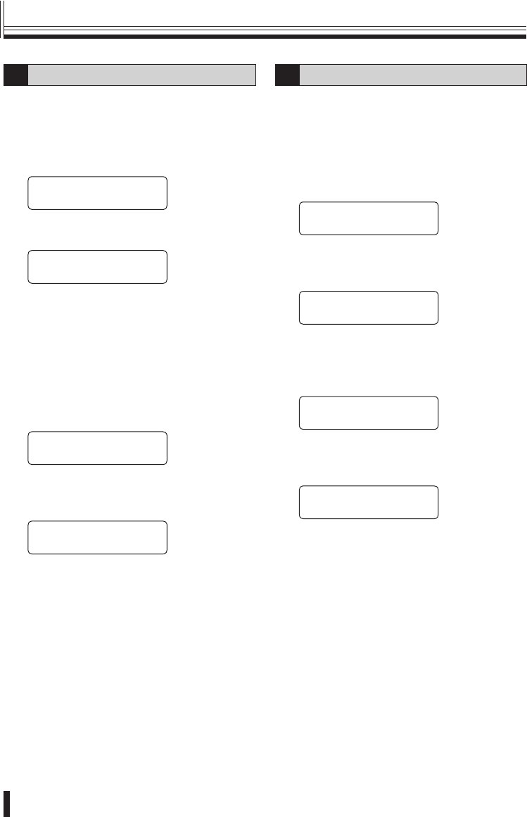
1Address setting
This selects the camera address.
All settings other than this one will be applied to
the selected address.
(Default setting: 001)
1Move the joystick up or down to
select “1. ADDRESS”.
[ñCAM SETUP001†]
1.ADDRESS: 001
2Move the joystick to the left or right
to select the address, and then press
the ENT button.
[ñCAM SETUP001†]
1.ADDRESS: 001
[ñCAM SETUP255†]
1.ADDRESS: 255
The address can also be selected
using the numeric buttons.
2Protocol setting
This selects the protocol to be used for
communication.
(Default setting: SSP)
1Move the joystick up or down to
select “2. PROTOCOL”.
[ó
ñCAM SETUP001†]
2.PROTOCOL:SSP
2Move the joystick to the left or right
to select the protocol.
The camera address will vary depending on
the protocol selected.
Available settings: SSP (001−127)
PEL-D (001−255)
HSSP (001−127)
3Move the joystick up or down to
select “7. SAVE”, and then move the
joystick to the right.
“OK” will be displayed and the settings will
be saved.
[ó
ñCAM SETUP001 ]
7.SAVE ·
UP001 ]
OK
4Move the joystick up or down to
select “8. EXIT”, and then move the
joystick to the right.
Returns to the initial screen.
[óCAM SETUP001 ]
8.EXIT ·
▼
SANYO SSP 19.2k
CAM:001 D1 CH01
Camera settings (continued)
01GB_L8CSE_WA_VSP3000.indd 2101GB_L8CSE_WA_VSP3000.indd 21 2008/02/29 13:17:052008/02/29 13:17:05
Preparations 22
Camera settings
3Baud rate setting
This sets the communication speed.
(Default setting: 19.2 Kbps)
1Move the joystick up or down to
select “3. BAUDRATE”.
[ó
ñCAM SETUP001
◆
]
3.BAUDRATE:19.2k
2Move the joystick to the left or right
to select the communication speed.
Available settings:
2.4k, 4.8k, 9.6k, 19.2k, 38.4k, 57.6k
3Move the joystick up or down to
select “7. SAVE”, and then move the
joystick to the right.
“OK” will be displayed and the settings will
be saved.
[ó
ñCAM SETUP001 ]
7.SAVE ·
UP001 ]
OK
4Move the joystick up or down to
select “8. EXIT”, and then move the
joystick to the right.
Returns to the initial screen.
[óCAM SETUP001 ]
8.EXIT ·
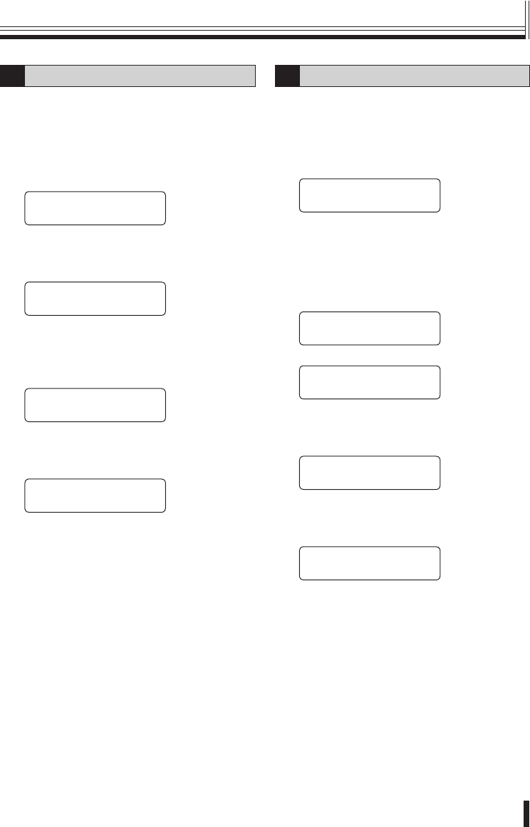
4Pan and tilt speed setting
The speed of pan and tilt operations for the
camera is controlled by the degree of tilt of the
joystick.
(Default setting: OFF)
1Move the joystick up or down to
select “5. PROP.”.
[ó
ñCAM SETUP001†]
5.PROP.: OFF
Available settings:
ON: Variable
OFF: Constant
2Move the joystick to the left or right
to select “ON” or “OFF”.
3Move the joystick up or down to
select “7. SAVE”, and then move the
joystick to the right.
“OK” will be displayed and the settings will
be saved.
[ó
ñCAM SETUP001 ]
7.SAVE ·
UP001 ]
OK
4Move the joystick up or down to
select “8. EXIT”, and then move the
joystick to the right.
Returns to the initial screen.
[óCAM SETUP001 ]
8.EXIT ·
01GB_L8CSE_WA_VSP3000.indd 2201GB_L8CSE_WA_VSP3000.indd 22 2008/02/29 13:17:052008/02/29 13:17:05

Preparations
23
5DVR address and channel
setting
This assigns the DVR address and channel
number to the selected camera.
For details, refer to “Camera address numbers
(default value)”. See page 31.
1Move the joystick up or down to
select “6. DVR”.
The “01” setting assigned to the first DVR
will flash.
[ó
ñCAM SETUP001†]
6.DVR:01 CH:01
2Move the joystick to the left or
right to select the address for the
connected DVR (Example: 03), and
then press the ENT button.
The cursor will move to “01” and it will flash.
DVR address: 01−99
[ó
ñCAM SETUP001†]
6.DVR:03 CH:01
3Move the joystick to the left or
right to select the channel number
(Example: 16), and then press the
ENT button.
Channel number: 01−16
[ó
ñCAM SETUP001†]
6.DVR:03 CH:16
4Move the joystick up or down to
select “7. SAVE”, and then move the
joystick to the right.
“OK” will be displayed and the settings will
be saved.
[ó
ñCAM SETUP001 ]
7.SAVE ·
UP001 ]
OK
5Move the joystick up or down to
select “8. EXIT”, and then move the
joystick to the right.
Returns to the initial screen.
[óCAM SETUP001 ]
8.EXIT ·
Camera settings (continued)
01GB_L8CSE_WA_VSP3000.indd 2301GB_L8CSE_WA_VSP3000.indd 23 2008/02/29 13:17:052008/02/29 13:17:05
Operation 24
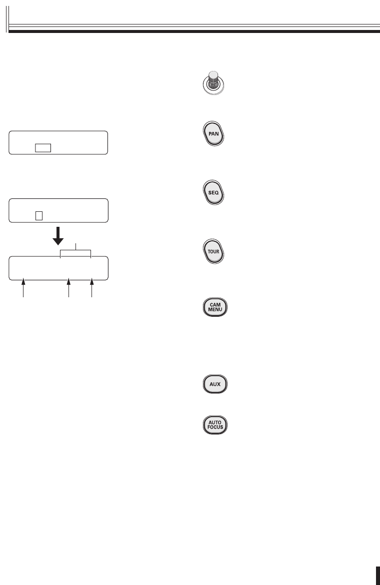
Camera operation buttons
Joystick:
When in camera mode and a camera
menu is not being displayed, this can
be used to carry out pan, tilt and zoom
operations.
AUTO PAN START: (P27)
When this button is pressed, automatic
panning is carried out between the
preset panning positions.
When some other operation is carried
out, automatic panning stops.
AUTO SEQ START: (P27)
When this button is pressed, sequential
panning is carried out between the
preset sequential positions.
When some other operation is carried
out, automatic sequential panning stops.
AUTO TOUR START: (P27)
When this button is pressed, the camera
starts moving along the path that has
been preset at the camera.
When some other operation is carried
out, automatic tour operation stops.
OPEN CAM MENU?:
This is used to display the camera
menu. You will be prompted to enter a
password in order to display the menu.
For details, refer to “Operating the
camera by changing camera menu
settings using the system controller”.
See page 25.
AUX ON:
Turns on and off an auxiliary function.
For details, refer to “Auxiliary function
operation”. See page 26.
AUTO FOCUS:
Automatically focuses the images which
are currently being monitored.
■Operating the camera from the
system controller
Press the button corresponding to the
number of the camera to be operated
(Example: 2), and then press the ENT
button.
SANYO SSP 19.2k
CAM:001 D1 CH01
Camera 2 will be selected and the channel
connected to DVR 01 will change to 2.
For details, refer to “Camera address numbers
(default value)”. See page 31.
SANYO SSP 19.2k
CAM:2–
SANYO SSP 19.2k
CAM:002 D1 CH02
CA B
D
A Currently-selected camera address number
(CAM:002)
B Currently-connected DVR number (D1)
C Channel number of currently-connected DVR
(CH02)
D Communication protocol (SSP)/speed (19.2k)
■
Camera operations
01GB_L8CSE_WA_VSP3000.indd 2401GB_L8CSE_WA_VSP3000.indd 24 2008/02/29 13:17:062008/02/29 13:17:06

Operation
25
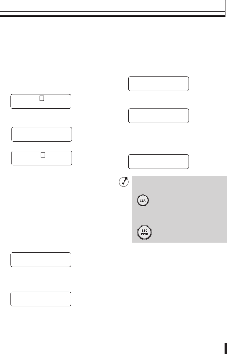
FOCUS NEAR:
Adjusts the focus to the nearest object.
FOCUS FAR:
Adjusts the focus to the furthest object.
GO PRESET P:
The camera will move to the preset
position which has been recorded.
For details, refer to “Preset position
retrieval operation”. See page 26.
MEM.PRESET: ?:
Lets you record an object into a preset
setting.
For details, refer to “Preset memory
operations”. See page 26.
IRIS OPEN:
Increases the iris level setting.
IRIS CLOSE:
Decreases the iris level setting.
Operating the camera by changing
camera menu settings using the
system controller
1Press the CAM MENU button.
The “OPEN CAM MENU?” menu will be
displayed.
OPEN CAM MENU?
PASSWORD[ ---- ]
2No password is set initially, so simply
press the ENT button.
The camera’s menu screen will be displayed
on the monitor.
OPEN CAM MENU?
OK
▼
OPEN CAM MENU?
CAM:002
▼
SANYO SSP 19.2k
CAM:002 D1 CH02
While pressing the SHIFT/FUNC.
button, press the CAM MENU button to
exit the camera menu.
+
* Only available for the VCC-9500/9600/
9700/9800 series.
3Use the joystick to select a menu, and
then press the ENT button to display
the sub-menu.
For details on menu operations, refer to the
operating instructions for the camera.
■
Camera operations (continued)
01GB_L8CSE_WA_VSP3000.indd 2501GB_L8CSE_WA_VSP3000.indd 25 2008/02/29 13:17:072008/02/29 13:17:07
Operation 26
Camera operations
Auxiliary function operation
Transmits AUX ON/OFF commands to the
selected cameras.
For details, refer to “List of auxiliary
commands for Sanyo cameras”. (P30)
1Press the AUX button.
“AUX ON” will be displayed.
If the AUX button is pressed once more, the
display changes to “AUX OFF”.
AUX ON :–
1-16 ENT/ESC
2Press a numeric button (Example: 2)
and then press the ENT button.
AUX ON :2–
CAM:001
▼
AUX ON :2
1-16 ENT/ESC
Available settings:
Sanyo SSP/HSSP: 1−16
Pelco-D: 1−8
Preset position retrieval operation
This retrieves preset positions which have
been recorded by the camera beforehand.
Up to 255 settings can be retrieved. (Varies
depending on model.)
1Press the PRESET GO button.
“GO PRESET P” will be displayed.
GO PRESET P:–
1-255 ENT/ESC
2Press a numeric button (Example: 1)
and then press the ENT button.
The camera will move to preset position 1.
GO PRESET P:1
CAM:001
■
■
Preset memory operations
Records preset positions into the cameras.
First use the joystick or some other method
to select a preset position for the camera.
1Press the PRESET MEMORY button.
You will be prompted for the password.
MEM.PRESET:?
PASSWORD[ ---- ]
2No password is set initially, so simply
press the ENT button.
MEM.PRESET:–
1-255 ENT/ESC
3Press a numeric button (Example: 1)
to select the desired preset number,
and then press the ENT button.
Preset position 1 has now been recorded.
MEM.PRESET:1
CAM:001
If you make a mistake with a number
while entering any of the settings,
press the CLR button.
To return to another operation, press
the ESC/PWR button to return to the
initial screen.
•
•
■
01GB_L8CSE_WA_VSP3000.indd 2601GB_L8CSE_WA_VSP3000.indd 26 2008/02/29 13:17:082008/02/29 13:17:08
Operation
27
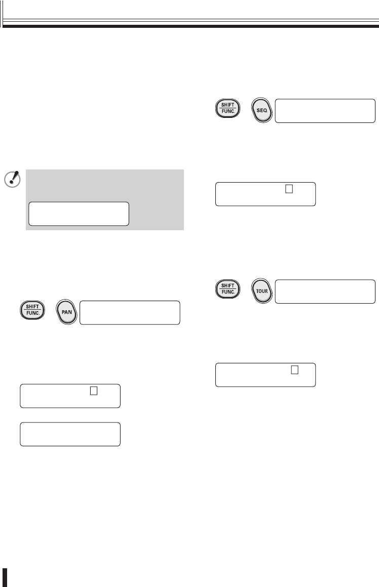
Retrieving pan, sequence and
tour operations recorded in a PTZ
camera
You can select preset pan, sequence and
tour operations so that these operations can
be carried out.
This operation is limited to the following
camera models which already contain preset
operations.
VCC-9500/9600/9700/9800 series
If you enter a number outside the range
of 1 to 4, “error” will be displayed, so
re-enter the number.
PAN PATTERN:
error
A Pan operation
1While pressing the SHIFT/FUNC.
button, press the PAN button.
“PAN PATTERN” will be displayed.
+ PAN PATTERN:–
1-4 ENT/ESC
2Press a numeric button (Example: 2)
and then press the ENT button.
The pan operation recorded for the selected
number will then be carried out.
Returns to the initial screen.
PAN PATTERN:2
CAM:002
▼
SANYO SSP 19.2k
CAM:001 D1 CH01
■
•
B Sequence operation
1While pressing the SHIFT/FUNC.
button, press the SEQ button.
“SEQ PATTERN” will be displayed.
+ SEQ PATTERN:–
1-4 ENT/ESC
2Press a numeric button (Example: 2)
and then press the ENT button.
The sequence operation recorded for the
selected number will then be carried out.
Returns to the initial screen.
SEQ PATTERN:2
CAM:002
C Tour operation
1While pressing the SHIFT/FUNC.
button, press the TOUR button.
“TOUR PATTERN” will be displayed.
+ TOUR PATTERN:–
1-4 ENT/ESC
2Press a numeric button (Example: 2)
and then press the ENT button.
The tour operation recorded for the selected
number will then be carried out.
Returns to the initial screen.
TOUR PATTERN:2
CAM:002
Camera operations (continued)
01GB_L8CSE_WA_VSP3000.indd 2701GB_L8CSE_WA_VSP3000.indd 27 2008/02/29 13:17:082008/02/29 13:17:08
Operation 28
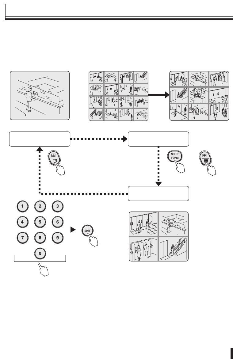
Switching the DVR screen display
The only DVR function that can be operated from the system controller is the screen display
switching function.
The monitor screen can be switched between multi-screen, quad-screen or single-screen
display by pressing the following buttons.
SANYO SSP 19.2k
CAM:001 D1 CH01
SANYO SSP 19.2k
MULTI D1 CH--
(Multi-screen display)
(Quad-screen display)
(Single-screen display)
SANYO SSP 19.2k
QUAD D1 CH--
0302
05 06
01
04
07 08 09
12
16
03 04
13 14 15
07 08
09 10 11 12
01 02
05 06
02
0201
0403
+
While pushing
■
DVR operation
01GB_L8CSE_WA_VSP3000.indd 2801GB_L8CSE_WA_VSP3000.indd 28 2008/02/29 13:17:092008/02/29 13:17:09
Operation
29
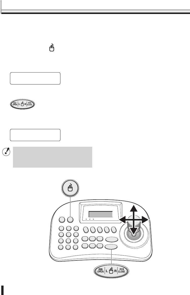
1Press the mouse ( ) button.
“MOUSE MODE” will be displayed, and you
can then use the joystick to move the cursor.
Camera operations cannot be carried out at
this time.
SANYO SSP 19.2k
MOUSE MODE
L button: Left click
R button: Right click
2Press the mouse button once more.
The display will return to the initial screen and
camera operations can then be carried out.
SANYO SSP 19.2k
CAM:001 D1 CH01
If using this function, first use the
menu settings to activate the function.
For details, refer to “8 Mouse setting”.
See page 17.
Use the accessory USB cable to connect a DVR with mouse function (such as the HD-8000)
to the USB mouse port at the rear of the system controller.
For details on the connection method, refer to P12.
Operating a DVR with mouse function
01GB_L8CSE_WA_VSP3000.indd 2901GB_L8CSE_WA_VSP3000.indd 29 2008/02/29 13:17:092008/02/29 13:17:09

Others 30
List of auxiliary commands for Sanyo cameras
The commands are examples of commands for the VCC-9500/9600/9700/9800 series.
Auxiliary
command
ON OFF Operation
1 Switch to Color Mode Pan/Tilt control 1 Switches a day/night camera to color
mode.
2 Switch to B/W Mode Pan/Tilt control 2 Switches a day/night camera to black
& white mode.
3 Switch to Day/Night Auto
Mode
Pan/Tilt control 3 Switches a day/night camera to day/
night automatic mode.
4 AUTO RETURN Function
ON
AUTO RETURN Function
OFF
For a description of the automatic
return function, refer to the instruction
manual.
5 GLOBAL ADDRESS
Function ON
GLOBAL ADDRESS
Function OFF
For Pelco-D only. Address 99 allows
all cameras to receive the command
and operate.
6 REMOTE SET REMOTE RESET Only enabled when alarm output 2 is
set to “REMOTE”. For details, refer to
the instruction manual.
7−−−
8 ALARM DISABLE
Function ON
ALARM DISABLE
Function OFF
Alarms cannot be received for a
set period of time during and after
operation of a PTZ camera.
For a description of the alarm disable
function, refer to the instruction
manual.
9 AUTO PURSUIT Function
ON
AUTO PURSUIT Function
OFF
VCC-9700/9800 series only.
For details on the automatic pursuit
function, refer to the instruction
manual.
* Auxiliary commands 1, 2 and 3 are also valid for day/night-type zoom cameras.
■
Appendices
01GB_L8CSE_WA_VSP3000.indd 3001GB_L8CSE_WA_VSP3000.indd 30 2008/02/29 13:17:092008/02/29 13:17:09
Others
31
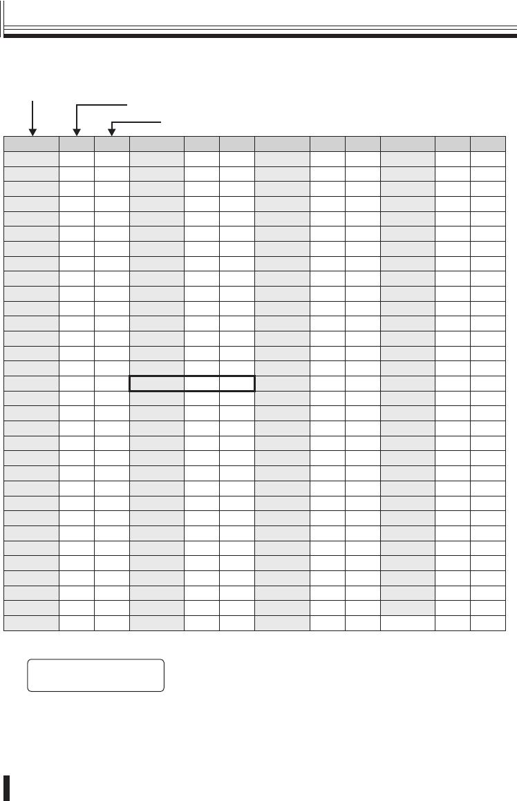
Camera address numbers (default value)
Camera address
Connected DVR
Connected channel No.
CAM No. DVR CH CAM No. DVR CH CAM No. DVR CH CAM No. DVR CH
1 11333165519771
2 12343266529872
3 13353367539973
4 143634685410074
5 153735695510175
6 163836705610276
7 173937715710377
8 184038725810478
9 194139735910579
10 1 10 42 3 10 74 5 10 106 7 10
11 1 11 43 3 11 75 5 11 107 7 11
12 1 12 44 3 12 76 5 12 108 7 12
13 1 13 45 3 13 77 5 13 109 7 13
14 1 14 46 3 14 78 5 14 110 7 14
15 1 15 47 3 15 79 5 15 111 7 15
16 1 16 48 3 16 80 5 16 112 7 16
17 2 1 49 4 1 81 6 1 113 8 1
18 2 2 50 4 2 82 6 2 114 8 2
19 2 3 51 4 3 83 6 3 115 8 3
20 2 4 52 4 4 84 6 4 116 8 4
21 2 5 53 4 5 85 6 5 117 8 5
22 2 6 54 4 6 86 6 6 118 8 6
23 2 7 55 4 7 87 6 7 119 8 7
24 2 8 56 4 8 88 6 8 120 8 8
25 2 9 57 4 9 89 6 9 121 8 9
26 2 10 58 4 10 90 6 10 122 8 10
27 2 11 59 4 11 91 6 11 123 8 11
28 2 12 60 4 12 92 6 12 124 8 12
29 2 13 61 4 13 93 6 13 125 8 13
30 2 14 62 4 14 94 6 14 126 8 14
31 2 15 63 4 15 95 6 15 127 8 15
32 2 16 64 4 16 96 6 16
The camera address for channel 16 of DVR3 is 48.
[ó
ñCAM SETUP048†]
6.DVR:03 CH:16
■
•
Appendices (continued)
01GB_L8CSE_WA_VSP3000.indd 3101GB_L8CSE_WA_VSP3000.indd 31 2008/02/29 13:17:102008/02/29 13:17:10
Others 32
Communication format RS485, RS-422
Keyboard 29 keys
Joystick 3-axis joystick (pan / tilt / zoom)
Control communication terminal Tx1, Tx2, Tx3, TRx
Protocol SSP, H-SSP, Pelco-D
USB mouse port Compatible with DVRs with mouse function
Communication speed 2400, 4800, 9600, 19200, 38400, 57600 bps
Max. number of connectable
units
256
Cameras: SSP/HSSP: 127, Pelco-D: 255
Controllers: 5
Digital video recorders: 99
•
•
•
Operating environment Temperature: 5° to 40°C
Humidity: 80% or lower
Storage environment Temperature: −20° to 60°C
Humidity: 80% or lower
Power supply (AC adapter) Input voltage: 100−240 V AC 50/60Hz
Output voltage: 12 V DC
Current consumption 0.2 A
Weight 750 g
Appearance and specifi cations are subject to change without prior notice.
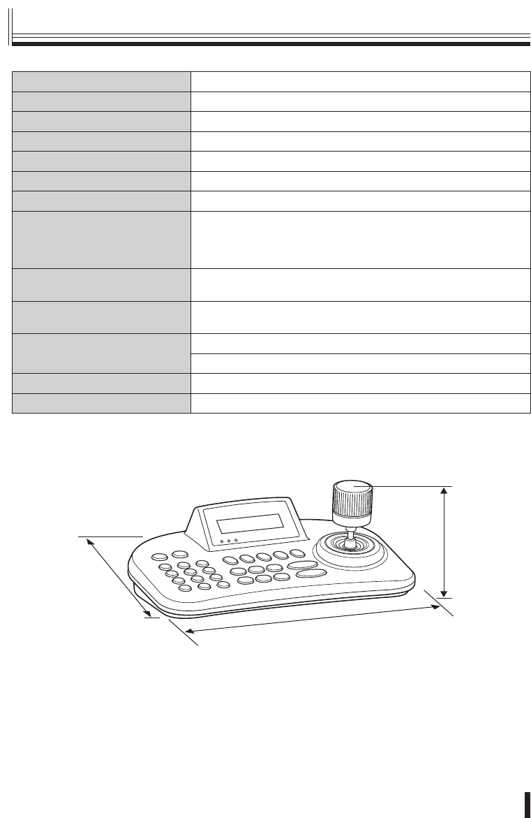
External dimensions
(Units: mm)
280
100
180
■
Specifi cations
01GB_L8CSE_WA_VSP3000.indd 3201GB_L8CSE_WA_VSP3000.indd 32 2008/02/29 13:17:102008/02/29 13:17:10

SANYO Electric Co., Ltd.
01GB_L8CSE_WA_VSP3000.indd 3301GB_L8CSE_WA_VSP3000.indd 33 2008/02/29 13:17:102008/02/29 13:17:10
