Sargent 45066 CR ED6000 INSTALLATION INSTRUCTIONS FOR 7800/8200 MORTISE LOCK 8200installation
User Manual: Sargent INSTALLATION INSTRUCTIONS FOR 7800/8200 MORTISE LOCK Instruction Sheets
Open the PDF directly: View PDF ![]() .
.
Page Count: 2
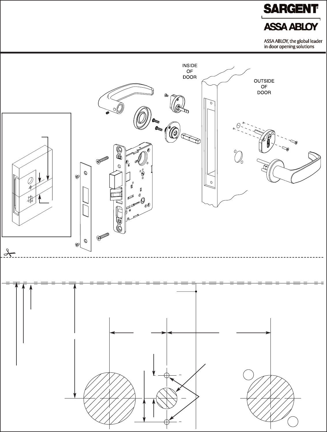
TEMPLATE LAYOUT
ON DOOR EDGE
A7623A
185P Occupancy Indicator shown
2-1/2"
CENTERLINE
OF LOCKBODY
CENTERLINE OF
LOCKBODY
2-1/2"1-3/8"
FOR METAL
DOORS: DRILL
(2) PILOT HOLES
0.106 (#36 DRILL)
AND TAP
(#6-32 UNC)
9/16"
9/16"
2-3/4"
LOW SIDE
OF DOOR
INSIDE RHRB
OUTSIDE LH
NO BEVEL
DOOR
HIGH SIDE
OF DOOR
INSIDE RH
OUTSIDE LHRB
1/2" DIA. HOLE
FOLD HERE ACCORDING TO DOOR HAND AND BEVEL
TOP
CYLINDER
LEVER OR
KNOB
Copyright ©2006, 2008, Sargent Manufacturing Company, an
ASSA ABLOY Group company. All rights reserved. Reproduction
in whole or in part without the express written permission of
Sargent Manufacturing Company is prohibited.
INSTALLATION INSTRUCTIONS FOR
7800/8200 MORTISE LOCK
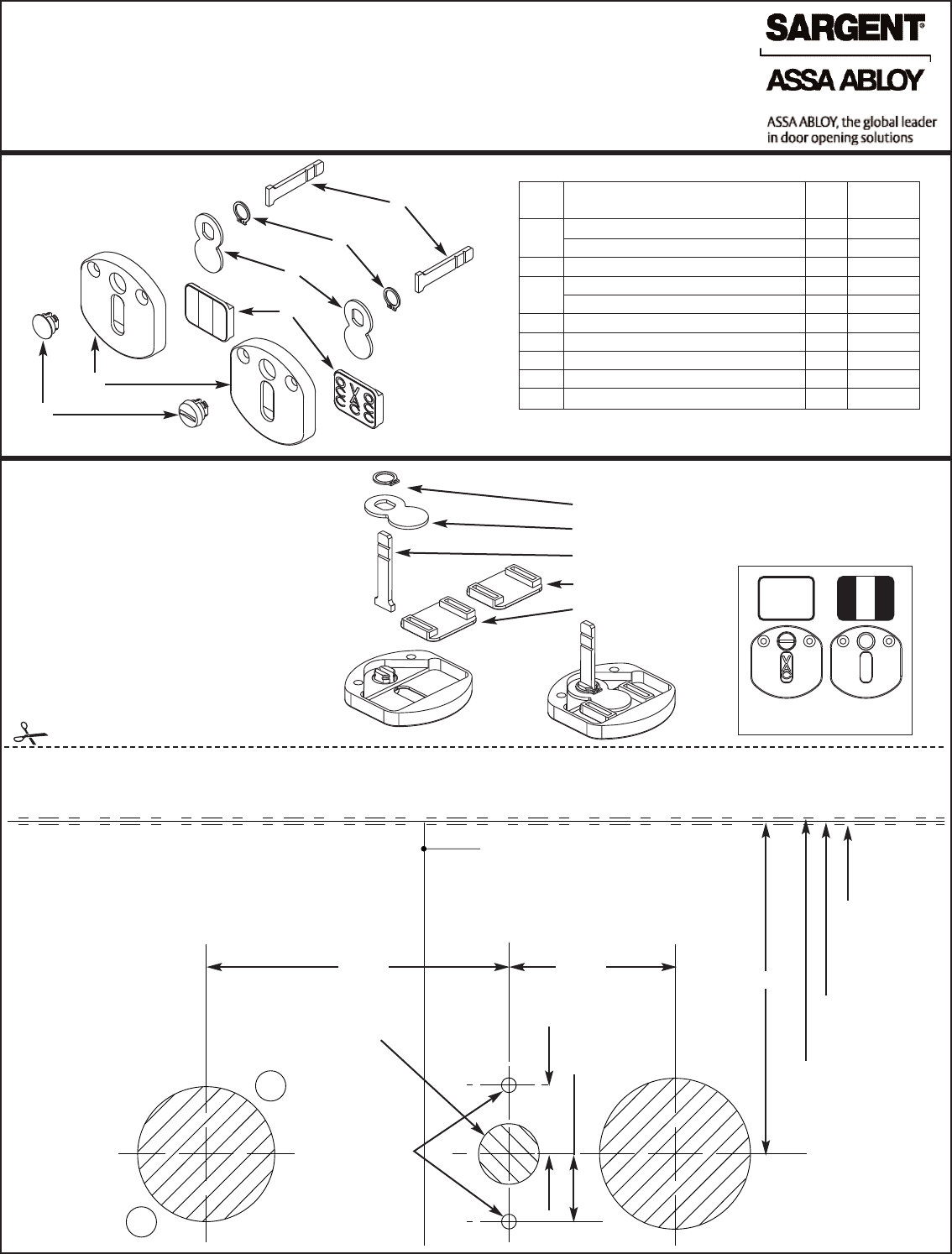
VISUAL(185C)/OCCUPANCY(185P) INDICATORS
For assistance contact SARGENT at 800-727-5477 or www.sargentlock.com
INSTALLATION INSTRUCTIONS FOR
7800/8200 MORTISE LOCK
VISUAL(185C)/OCCUPANCY(185P) INDICATORS
For assistance contact SARGENT at 800-727-5477 or www.sargentlock.com
A7623A
Item Description Qty. Part
Number
1Indicator Button 1 82-0592
Indicator Button–Emrgcy. Release 1 82-0591
2 Housing Plate 1 82-0589
3Red/White Slide 1 82-4050
VAC/OCC Slide 1 82-4051
4 Rotation Plate 1 82-0590
5 Snap Ring 1 01-4552
6 Spindle 1 77-1195
7 #6 x 5/8" Wood Screw (not shown) 2 01-2036
8 #6-32 x 1/2" MS (not shown) 2 01-1020
INSTRUCTIONS FOR CHANGING
INDICATOR SLIDES 1. SNAP RING
2. ROTATION PLATE
3. SPINDLE
4. RED/WHITE SLIDE
5. VAC/OCC SLIDE
O
C
C
O
C
C
V
A
C
185C
1
185P
2
3
4
5
6
CENTERLINE OF
LOCKBODY
2-1/2" 1-3/8"
FOR METAL
DOORS: DRILL
(2) PILOT HOLES
0.106 (#36 DRILL)
AND TAP
(#6-32 UNC)
9/16"
9/16"
2-3/4"
LOW SIDE
OF DOOR
INSIDE LHRB
OUTSIDE RH
NO BEVEL
DOOR
HIGH SIDE
OF DOOR
INSIDE LH
OUTSIDE RHRB
1/2" DIA. HOLE
185C
185P
1. REMOVE SNAP RING.
2. REMOVE PARTS 2, 3, & 4 OR 5.
3. REPLACE WITH ALTERNATE SLIDE.
4. REASSEMBLE PARTS 2 & 3.
NOTE: CHECK FOR PROPER ORIENTATION
OF VAC/OCC SLIDE TEXT.
5. REPLACE SNAP RING INTO GROOVE IN
BUTTON.
FOLD HERE ACCORDING TO DOOR HAND AND BEVEL
TOP
CYLINDER
LEVER OR KNOB
Copyright ©2006, 2008, Sargent Manufacturing Company, an
ASSA ABLOY Group company. All rights reserved. Reproduction
in whole or in part without the express written permission of
Sargent Manufacturing Company is prohibited.
