Sargent 421 Cam Action Door Closer (PCTB & PCHTB) Push Side Track Application Installation Instructions A7959A
User Manual: Sargent 421 Cam Action Door Closer (PCTB & PCHTB) Push Side Track Application Installation Instructions Instruction Sheets
Open the PDF directly: View PDF ![]() .
.
Page Count: 4
A7959A 1
421 CAM ACTION DOOR CLOSER
(PCTB & PCHTB) PUSH SIDE TRACK
APPLICATION INSTALLATION INSTRUCTIONS
CAUTION: FAILURE TO INSTALL OR ADJUST PROPERLY MAY RESULT IN INJURY OR DAMAGE
For assistance, contact SARGENT at 800-727-5477 or www.sargentlock.com
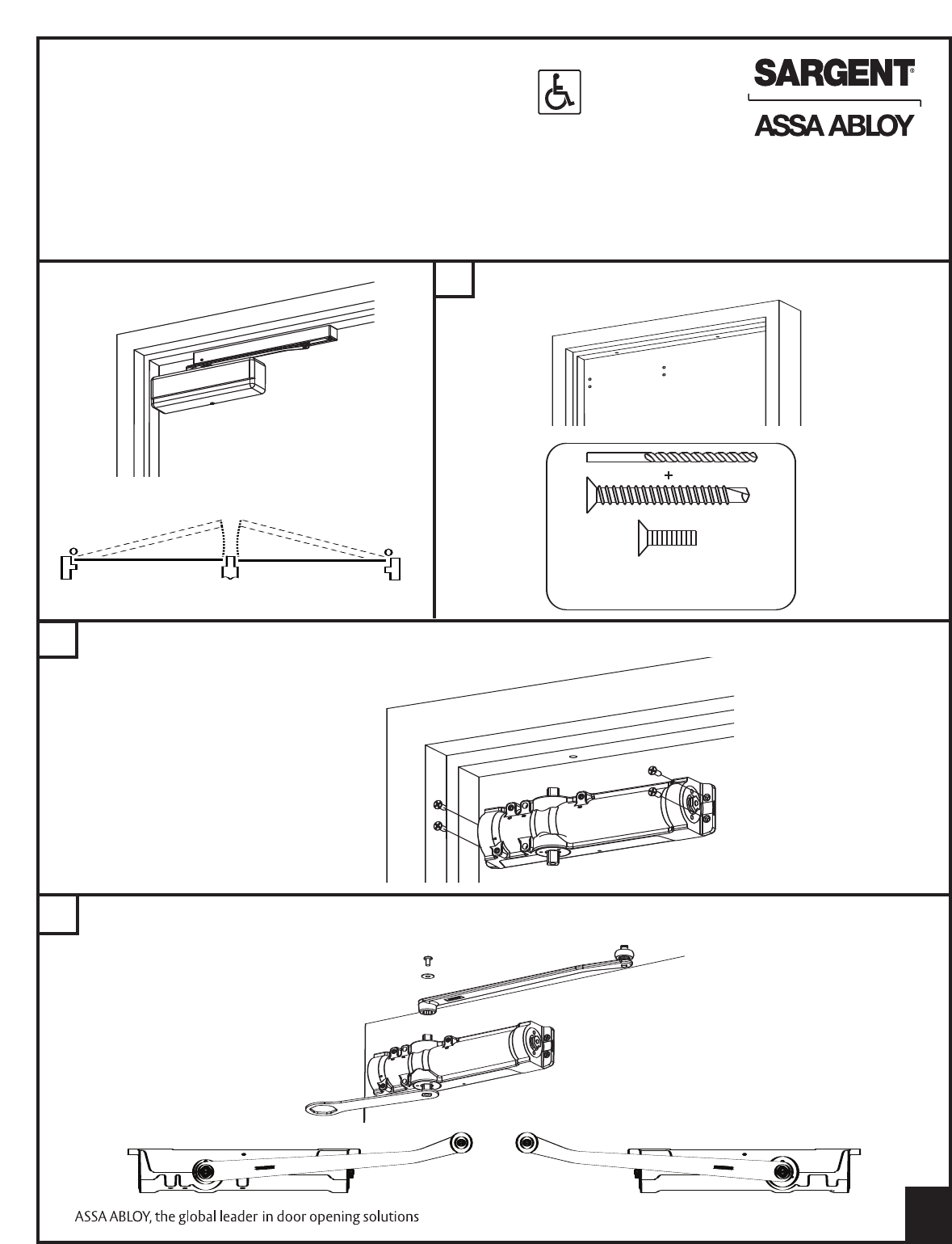
NOTE: AN AUXILIARY DOOR STOP IS REQUIRED
B
LEFT HAND
SHOWN
MEASURE & MARK HOLES. PREP HOLES USING DIMENSIONS
ON PAGE 4
CWITH A WRENCH, ROTATE THE BOTTOM SPINDLE TOWARD HINGE APPROXIMATELY 15°. SECURE ARM TO SPINDLE
WITH SCREW AND WASHER PROVIDED
A
HINGE SIDEHINGE SIDE
STOP SIDE STOP SIDE
RIGHT
HAND DOOR
LEFT
HAND DOOR
WITH PROVIDED FASTENERS, SECURE CLOSER BODY TO DOOR WITH POWER ADJUSTMENT FACING
AWAY FROM HINGE SIDE OF DOOR.
When using mortise nuts,
see accessories on page 3
Warning: If not properly indexed, door
closer will not operate properly
OR
Pre-drill - 3/32” holes
for self tapping screws or #16 drill and tap
#12-24 UNC for machine screws
©Sargent Manufacturing Company 2007
Left Hand Right Hand
Left Hand Shown
(Right Hand Opposite)
© Sargent Manufacturing Company 2007 A7959A
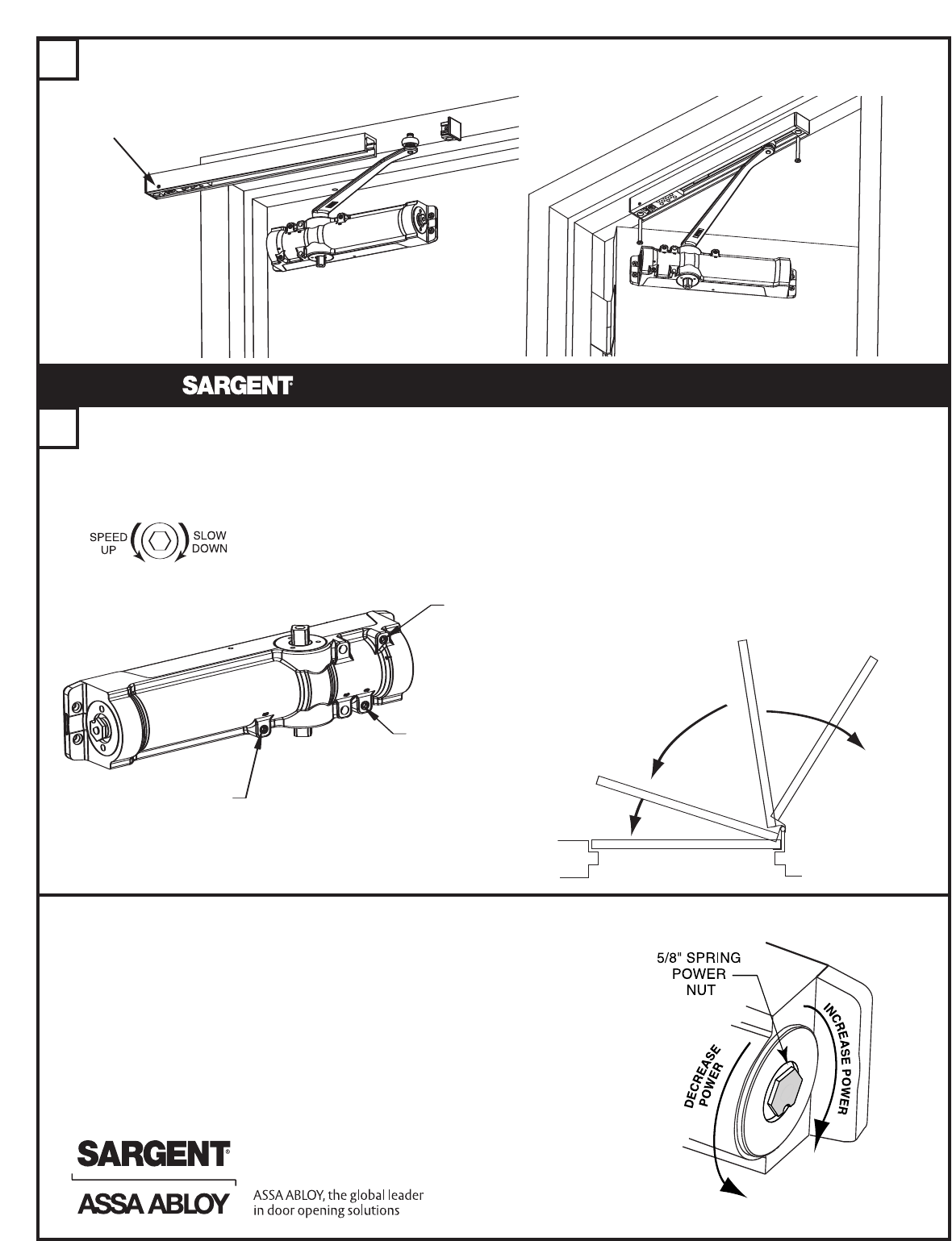
SLIDE TRACK OVER ROLLER AND INSTALL END CAPS. SECURE TRACK TO FRAME WITH SCREWS PROVIDED.
D
E
BACKCHECK
RANGE
CLOSING SPEED
RANGE
LATCHING SPEED
RANGE
–Adjust door speed and latching speed valves to achieve the desired closing time. 6 seconds minimum from 90° to the
closed position is recommended.
–If backcheck is required, adjust valve to achieve a slight cushioning effect. Auxiliary stop required.
Use 5/32" hex wrench to
adjust valves
ADJUST POWER TO MINIMUM REQUIRED TO RELIABLY CLOSE AND LATCH DOOR
–If door is hard to open, decrease power slightly
– If door does not latch, increase power as required
–Doors adjusted with high closing power to overcome strong
draft conditions may exceed ADA standards.
CLOSING SPEED
LATCHING SPEED
BACKCHECK
FINAL ADJUSTMENT AND REGULATING PROCEDURE
NOTE: ORIENT TRACK SO STOP PIN IS
ON HINGE SIDE OF DOOR
421 CLOSERS ARE
FIELD ADJUSTABLE
FOR SIZES 1-6
© Sargent Manufacturing Company 2007 A7959A
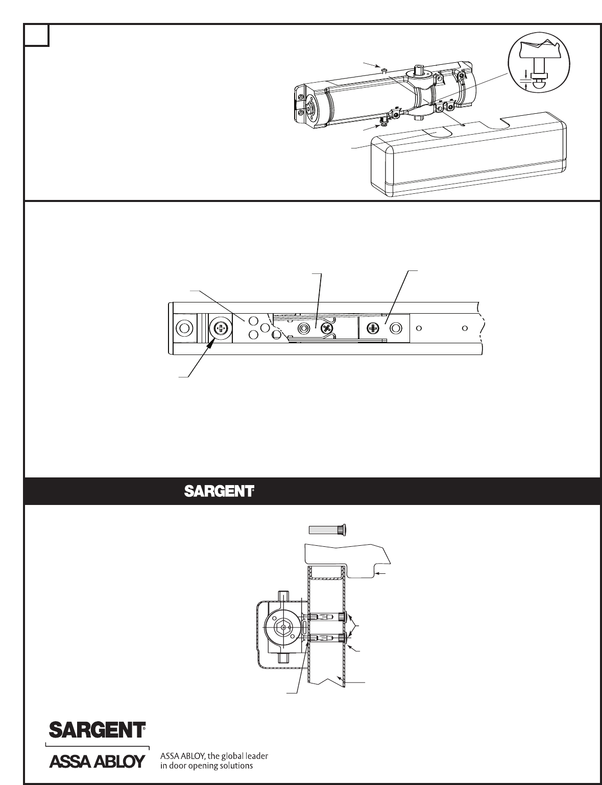
FOR MODELS HAVING “PCHT” HOLDER
ARMS
The holder device is set for 85° door holding position at the factory.
Tension is set at the highest setting.
HOLD OPEN
MECHANISM
BUMPER
STOP PIN
TENSIONER
F
GAP
Move insert
as needed
Small screw
Long screw
INSTALL COVER AS FOLLOWS:
1. SCREW SHORT COVER SCREW (#8-35 x 5/16)
INTO TOP OF CASE APPROXIMATELY 2 TURNS
2. ASSEMBLE PLASTIC SUPPORT AND LONG
COVER SCREW (# 8-32 x 1-1/4 ) INTO BOTTOM
OF CASE APPROXIMATELY 2 TURNS.
3. HOLD SUPPORT AGAINST CASE AND SLIDE
COVER INTO GAP BETWEEN FLANGE AND
SCREW HEAD
4. POSITION COVER ON CLOSER AND
TIGHTEN SCREWS
-To decrease holding tension: Remove tensioner mounting screw and move tension adjuster away
from hold open mechanism by using either of the two hole locations.
-To change hold open position: Remove hold open mechanism and tensioner mounting screws;
slide both to desired position and reinstall screws.
-To decrease the degree of door opening: Move stop pin to desired position
FRAME
UNREINFORCED
DOOR
DOOR STOP
MORTISE NUT
DRILL 3/8" DIA.
HOLE FOR MORTISE
NUT BODY
DRILL 1/4" DIA. HOLE
FOR MOUNTING SCREWS
Using optional mortise nuts when through-bolting
ACCESSORIES INFORMATION
MORTISE NUT INSTRUCTIONS
©Sargent Manufacturing Company 2007 A7959A
3/4"
RELEASEDATE
TEMPLATE NO
.
100 Sargent Drive New Haven, CT 06511
Manufacturing Company
8 May , 2007
C
LOF
HINGE
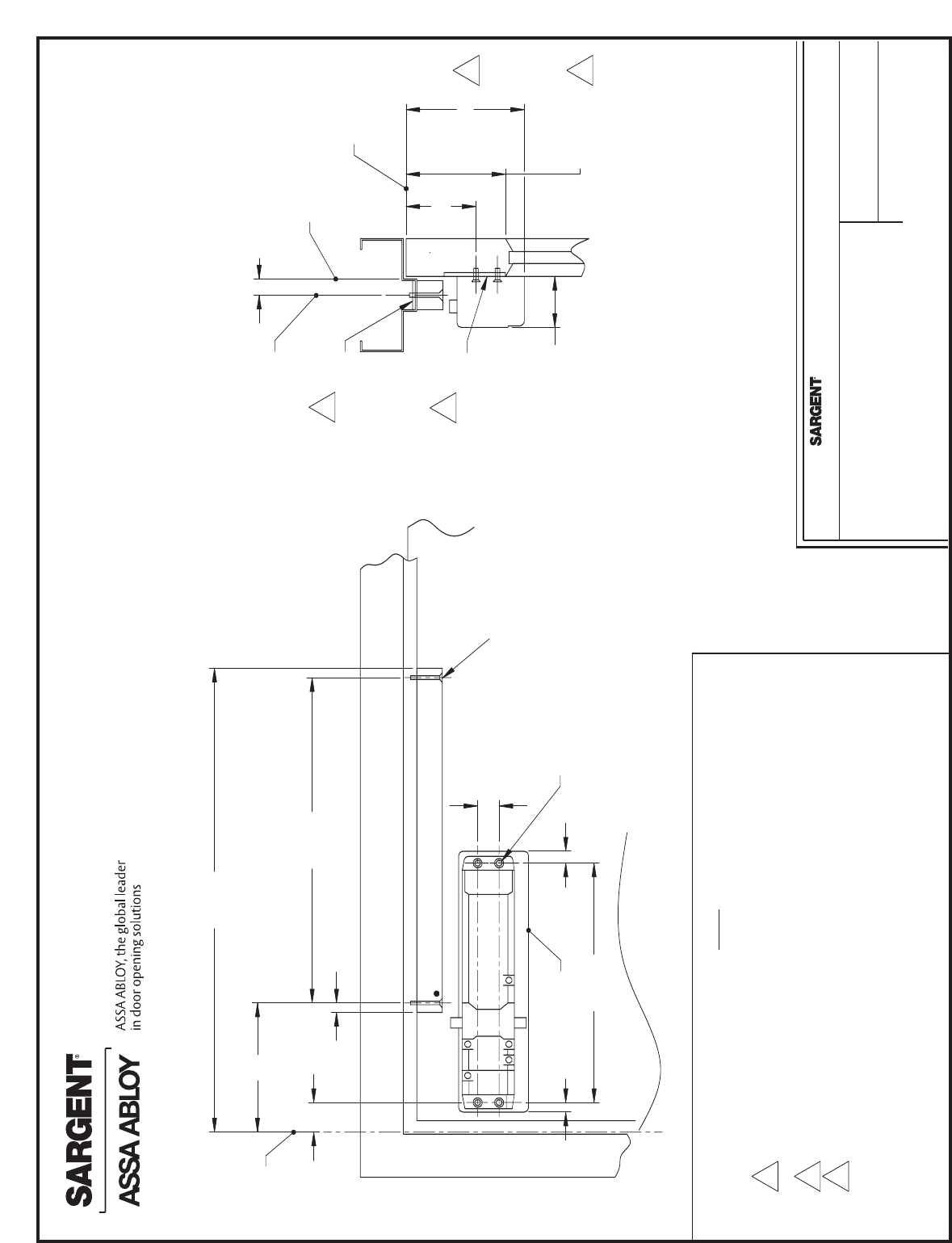
DATA SHEET
421 SERIES CLOSER WITH PCTB OR PCHTB
ARMS - PUSH SIDE APPLICATION
NOTE:
LEFT HAND DOOR SHOWN, RIGHT HAND OPPOSITE
1.
REINFORCE METAL DOORS AND FRAMES PER ANSI A250.8 AND
2.
SDI-100 , 12 GAUGE RECOMMENDED
USE 1431-J PLATE WHEN CLOSER BODY IS VISIBLE THROUGH GLASS
3.
THE MINIMUM TOP RAIL MAY BE REDUCED BY 3/4" BY USING THE
4.
1431-D MOUNTING PLATE. SEE TEMPLATE A7168
MAXIMUM OPENING POSITION 125°
5.
ADJUSTABLE HOLD OPEN RANGE: 75° -120° (HOLDER MODEL ONLY)
6.
AUXILIARY STOP REQUIRED
7.
FRAME
REINFORCEMENT
DOOR
REINFORCEMENT
2
2
#12-24 X 5/8 FLAT HEAD MACHINE
SCREW OR #12 X 1 1/2 SCREW
PROVIDED
#12-24 X 1 3/4 FLAT HEAD MACHINE
SCREW OR #12 x 1 3/4" SCREW PROVIDED
TOP OF
DOOR
3
TRACK
421 CLOSER
OUTLINE OF
COVER
FACE OF
STOP
4
C
LOF TRACK
A 7961 A
13/8"
6"
21 5/8"
1"
11 1/8"
1/2"1/2"
31/4"
TOP RAIL
23/8"
15 1/8"
4 5/8" MIN
51/2"
1/2"
