Saris Cycling Group SL2P401 Power Tap SL2.4 System User Manual
Saris Cycling Group Inc Power Tap SL2.4 System
UserManual.wiki
>
Saris Cycling Group
>
SL2P401 User Manual
>
User Manual
Contents
1.
User Manual
2.
user manual
User Manual
Navigation menu
Upload a User Manual
Namespaces
Wiki Guide
HTML
PDF
Info
Views
User Manual
Discussion / Help
Navigation


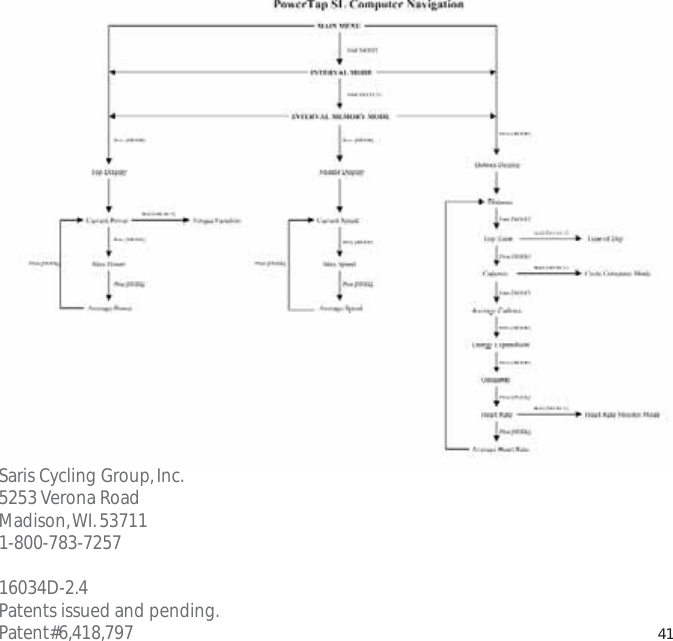
![3652558.I0WATTS3MID2.4General Computer OperationDDIISSPPLLAAYY LLEEVVEELLSSThe computer has three (3) main display levels:Top Power Middle Speed Bottom Multi-Function NOTE:These locations only apply to trip and interval modes and ddooeess nnoottapply to Cycle Computer or Heart Rate Monitor Function. See COMPUTER SETUP 4to customize display options.DDIISSPPLLAAYY MMOODDEESSThe computer has two (2) main modes of operation:1) Trip 2) Interval Hold [MODE] to toggle between display modes.BBUUTTTTOONNSSThere are two (2) buttons on the computer:1) [Mode]2) [Select]NOTE: [BRACKETED] words indicate buttons.There are five (5) types of button presses:1) Press [MODE] or [SELECT] - a single press and release of either [MODE] or [SELECT].Used for entering different modes and functionality.11TTRRAANNSS..IICCOONNIINNTTEERRVVAALLDDIISSPPLLAAYYMMOODDEE((LLEEFFTT))PPOOWWEERRDDIISSPPLLAAYYSSPPEEEEDDDDIISSPPLLAAYYMMUULLTTIIDDIISSPPLLAAYYBBOOTTHHSSEELLEECCTT((RRIIGGHHTT))Changes activemode Clear dataEnter setup Select function](https://usermanual.wiki/Saris-Cycling-Group/SL2P401.User-Manual/User-Guide-692178-Page-11.png)
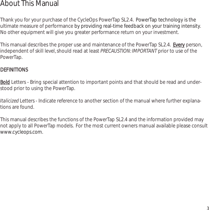
![2) Hold [MODE] or [SELECT] - a single button press and hold of either [MODE] or[SELECT] for 2 sec. Used for initiating a new Interval.3) Press [MODE] and [SELECT] - simultaneously press and release of bbootthh[MODE] and[SELECT].4) Hold [MODE] and [SELECT] - simultaneously press and hold bbootthh[MODE] and[SELECT] for 2 sec. NOTE: Continuing to hold longer than 2 sec. and releasing will clearall data.5) Extended Hold [MODE] and [SELECT] - simultaneously press and hold of bbootthh[MODE] and [SELECT] for ggrreeaatteerr tthhaann 55 sseecc. Used for initiating scrolling menu.SSCCRROOLLLLIINNGG MMEENNUU::PPOOWWEERR CCOONNSSEERRVVAATTIIOONNThe computer and hub have power saving features to prolong battery life.The computer powersdown the display after four (4) minutes of inactivity.Press either [MODE] or [SELECT] to activatethe display.Similarly,the hub powers down after five (5) minutes of inactivity. The transmissionicon will not be visible when the hub is asleep.To wake the hub spin the wheel and verify thetransmission icon is illuminated. 12 SSCCRROOLLLLIINNGG MMEENNUU:: FFiinndd:: If [MODE] and [SELECT] are released When “Find” is displayed the computer will find Search for the PowerTap hub. ccllrr:: If [MODE] and [SELECT] are released when clr is displayed AALLLL DDAATTAA WWIILLLL BBEE EERRAASSEEDD. SSEEtt:: If [MODE] and [SELECT] are released When SEt is displayed on the top level of the Screen, a flashing “E”, d and t on the middle Level and 12345 on the bottom level. E = exit, return to ride mode d = restore default settings T = test mode 1 2 3 4 = setup menus](https://usermanual.wiki/Saris-Cycling-Group/SL2P401.User-Manual/User-Guide-692178-Page-12.png)
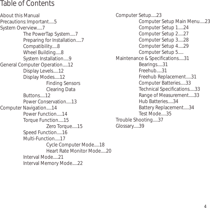
![Computer NavigationPPOOWWEERR FFUUNNCCTTIIOONNThe top level of the main display shows current,max,and average power readings.1) Press [MODE] to scroll the cursor to the top line of the main display2) Press [SELECT] to toggle through the power function options.For accurate power readings it is important to ffrreeqquueennttllyyzero the torque,see ZERO TORQUE.CCuurrrreenntt PPoowweerrPower is displayed in watts from 0-1999 in 1 watt increments. Current powerreadings are displayed only when the word “WATTS”appears below the top line(FIGURE 9). NOTE:If “WATTS”ddooeess nnoottappear under the top line the computer isin the Cycle Computer Function. To return to power readings see CYCLECOMPUTER MODE.MMaaxxiimmuumm PPoowweerrBoth “WATTS”and “MX”displayed simultaneously indicate the highest recordedpower output since the last time the data was cleared in trip mode or the selectedinterval in interval mode.(FIGURE 10)AAvveerraaggee PPoowweerrBoth “WATTS”and “AVG”displayed simultaneously indicate the average power output since the last time the data was cleared in trip mode or the selected interval in interval mode.(FIGURE 11)133652558.I0WATTS3MID8492558.I0MX WATTS3MIDI952558.I03MIDAV WATTSFIGURE 9FIGURE 10FIGURE 11](https://usermanual.wiki/Saris-Cycling-Group/SL2P401.User-Manual/User-Guide-692178-Page-13.png)
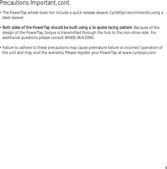
![TTOORRQQUUEE FFUUNNCCTTIIOONNShows the torque placed on the hub in inch-pounds. To display torque in trip mode:1) Press [MODE] to scroll the cursor to the top line of the main display.2) Press [SELECT] until the current power function is displayed.3) Hold [SELECT] until the word ‘WATTS”begins to flash. A blinking “WATTS”display indicates the torque function is currently displayed.4) Press [SELECT] to return to the current power function.(FIGURE 12).3MID0002558.I0 IMPORTANT: ZERO TORQUE Frequently the torque must be zeroed to ensure the most accurate power information is displayed. If the current power display is positive or negative while coasting the torque must be zeroed. This operations must be done while coasting with no tension on the chain, no tension placed on the pedals, and the transmission icon must be illuminated. To zero torque: 1) Press [MODE] to scroll the cursor to the top line of the main display. 2) Press [SELECT] until current power function is displayed. 3) Hold [SELECT] until the word “WATTS” begins to flash to enter the torque function. 4) Hold [SELECT] again until “0” is shown. 5) Press [SELECT] to return to current power. The current power function will now read zero while coasting. 14FIGURE 12](https://usermanual.wiki/Saris-Cycling-Group/SL2P401.User-Manual/User-Guide-692178-Page-14.png)
![SSPPEEEEDD FFUUNNCCTTIIOONNThe middle level of the main display shows current,max,and average speed readings.1) Press [MODE] to scroll the cursor to the middle line of the main display.2) Press [SELECT] to toggle through the speed function options.CCuurrrreenntt SSppeeeeddSpeed is displayed in either miles per hour (MI) or kilometers per hour (KM) up to99.9 mi/hr or km/hr in 0.1 mi/hr or km/hr increments. Current speed readings aredisplayed when only “MI”or “KM”appears below the middle line.(FIGURE 13)MMaaxxiimmuumm SSppeeeeddEither “MI”or “KM”and “MX”displayed simultaneously indicate the highest record-ed speed since the last time data was cleared in trip mode or the selected intervalin interval mode.(FIGURE 14)AAvveerraaggee PPoowweerrEither “MI” or “KM” and “AVG” displayed simultaneously indicate the average recorded speed since the last time data was cleared in trip mode or the selectedinterval in interval mode.(FIGURE 15)153652558.I0WATTS3MID3653358.I0WATTS7MX MID3652058.I03AV MIDWATTSFIGURE 13FIGURE 14FIGURE 15](https://usermanual.wiki/Saris-Cycling-Group/SL2P401.User-Manual/User-Guide-692178-Page-15.png)
![MMUULLTTII--FFUUNNCCTTIIOONN DDIISSPPLLAAYYDDiissttaannccee ((DD))Total trip or the selected interval distance in interval mode is displayed in miles orkilometers from 0.00 to 999.99 (FIGURE 16).1) Press [MODE] to scroll the cursor to the bottom line of the main display.2) Press [SELECT] to toggle through the multi-function displays until the “D”icon is displayed.NOTE:Distance is displayed in the same units as speed.TTrriipp TTiimmee aanndd TTiimmee ooff DDaayy ((TT))Total trip time,interval time,and time of day is displayed to 9:59:59 (FIGURE 17).1) Press [MODE] to scroll the cursor to the bottom line of the main display.2) Press [SELECT] to toggle through the multi-function displays until the “T”icon isdisplayed.3) While in trip time hold [SLECET] to access the real time clock.4) Hold [SELECT] to return to trip or interval time.NOTE:Auto start and stop with rotation of the wheel is the default setting.To customize autostart and stop see COMPUTER STETUP 4.3652558.I0WATTS3MI365252.5 I.43WATTS3MIT DFIGURE 16FIGURE 17](https://usermanual.wiki/Saris-Cycling-Group/SL2P401.User-Manual/User-Guide-692178-Page-16.png)
![CCaaddeennccee ((CC))Cadence is measured at the hub by analyzing the way a rider applies torquethrough the pedal stroke since there are natural power differences in the pedalstroke. The rate of pedaling is shown from 20 to 240 RPM.NOTE:An optional wireless cadence sensor is available to measure cadence atthe crank.1) Press [MODE] to scroll the cursor to the bottom line of the main display.2) Press [SELECT] to toggle through the multi-function displays until the "C" icon is displayed.(FIGURE 18)173652589WATTS3MICFIGURE 18CCYYCCLLEE CCOOMMPPUUTTEERR MMOODDEEAccess to the Cycle Computer Mode is also gained in the cadence function.This fun-tion allows the PowerTap SL2.4 computer to function as a cycle computer in theabsence of the PowerTap hub.This function is useful when the PowerTap SL2.4 hub isnot present such as in racing situations where lighter racing wheels are used.NOTE:InCycle Computer Mode heart rate is displayed in the top line of the main display andpower data is no longer displayed.To enter Cycle Computer Mode:1) Press [MODE] to scroll the cursor to the bottom line of the main display.2) Press [SELECT] to toggle through the mult-function displays until the “C”icon is dis-played.3) Hold [SELECT] and the word “WATTS”will disappear from below the top line.Placemagnet or rear wheel so it passes the receiver at the line or the sensor.4) To return to current power function hold [SELECT] until the word “WATTS”is dis-played under the top line of the main display.](https://usermanual.wiki/Saris-Cycling-Group/SL2P401.User-Manual/User-Guide-692178-Page-17.png)
![AAvveerraaggee CCaaddeennccee ((CC && AAVVGG))The average cadence displays data since the last time data was cleared in tripmode or the selected interval in interval mode. Average cadence is displayed inRPM.1) Press [MODE] to scroll the cursor to the bottom line of the main display.2) Press [SELECT] to toggle through the multi-function displays until the “C” and“AVG”is displayed.(FIGURE 19)EEnneerrggyy EExxppeennddiittuurree ((EE))The total work done over the course of the trip or interval is shown in kilojoules.This value is a measure of the total energy expended over the course of your ride.This is roughly equivalent to dietary calories expended.1) Press [MODE] to scroll the cursor to the bottom line of the main display.2) Press [SELECT] to toggle through the multi-function displays until the “E”is dis-played.(FIGURE 20)OOddoommeetteerr ((OO))Total accumulated distance traveled since the last system reset is displayed inmiles or kilometers. To manually input the your odometer reading see COMPUTERSETUP 1.1) Press [MODE] to scroll the cursor to the bottom line of the main display.2) Press [SELECT] to toggle through the multi-function displays until the “O”is displayed.(FIGURE 21)183652576WATTS3MIC AV365252009WATTS3MIE365252584WATTS3MIOFIGURE 19FIGURE 20FIGURE 21](https://usermanual.wiki/Saris-Cycling-Group/SL2P401.User-Manual/User-Guide-692178-Page-18.png)
![HHeeaarrtt RRaattee (())Current heart rate is shown up to 255 beats per minute (BMP). You must wear theheart rate chest strap to enable the heart rate measurement function. NOTE:ThePowerTap SL2.4 uses a coded chest strap.1) Press [MODE] to scroll the cursor to the bottom line of the main display.2) Press [SELECT] to toggle through the multi-function displays until the “ ”isdisplayed.(FIGURE 22)1936525I72WATTS3MI HEART RATE MONITOR MODE Access to the Heart Rate Monitor Mode is also gained in the current heart rate mode. This function allows the PowerTap computer to function as a heart rate monitor in the absence of the PowerTap hub. NOTE: In Heart Rate Monitor Mode heart rate is displayed on the top line of the main display and power data is no longer displayed. 1) Press [MODE] to scroll the cursor to the bottom line of the main display. 2) Press [SELECT] to toggle through the multi-function displays until the ( ) icon is displayed. 3) Hold [SELECT] and the words “watts” disappears from below the top line. 4)To return normal PowerTap functions hold [SELECT] until the word “WATTS” is displayed under the top line of the main display. FIGURE 22](https://usermanual.wiki/Saris-Cycling-Group/SL2P401.User-Manual/User-Guide-692178-Page-19.png)
![AAvveerraaggee HHeeaarrtt RRaattee ((AAVV))This value is a running average of the heart rate in BPM. If there is no heart rateinformation this will display as 0.1) Press [MODE] to scroll the cursor to the bottom line of the main display.2) Press [SELECT] to toggle through the multi-function displays until the “ AAVV”isdisplayed.(FIGURE 23)IINNTTEERRVVAALL MMOODDEEThe computer has two display modes. The trip mode shows total trip met-rics,and the interval mode displays interval specific information.The inter-val mode functions as a lap marker and is essentially always on.To begin the first interval,or advance to the next interval:Press and release [MODE] and [SELECT] simultaneously. NNOOTTEE:: DDoo nnootthhoollddbbootthh bbuuttttoonnss ddoowwnn aass yyoouu wwiillll cclleeaarr aallll ddaattaa ffrroomm tthhee ccoommppuutteerr.. In trip mode “INT” and the new interval number will appear and disappear(FIGURE 24). The computer can mark an unlimited number of intervalsalthough after nine (9) the marker will begin to count back at one (1). Forexample, interval ten (10) is displayed following interval (9) as one (1). To view interval specific data (power, speed, and multi-function display) from any location on thedisplay:1) Hold [MODE] until “INT”appears on the left hand side of the display. The “INT”and intervalnumber will remain illumined as a forth line in the main display (FIGURE 24). The data displayedis that of the current interval number shown.2)To exit back out of interval mode hold [MODE] until “INT”disappears. 2036525152WATTS3MIAVwattsspeedintmultiFIGURE 23FIGURE 24](https://usermanual.wiki/Saris-Cycling-Group/SL2P401.User-Manual/User-Guide-692178-Page-20.png)
![IINNTTEERRVVAALL MMEEMMOORRYY MMOODDEETo access stored interval data for the pprreevviioouuss 99 iinntteerrvvaallss oonnllyy:1) Enter the interval mode hold [MODE] until “INT”appears on the left hand side of the display.2) Press [MODE] to scroll until the “INT”flashes. NOTE:INT now constitutes a fourth level of dis-play.3) Hold [SELECT] and the memory icon (”M”) appears next to the interval number (FIGURE 25).4) With “INT”flashing,press [SELECT] to advance to the interval you wish to view.5) Press [MODE] scroll the cursor to the line of information you wish to view. NOTE:Recoveryperiods as well as work periods are displayed in memory mode.To exit back out of the interval memory mode hold [SELECT] until the memory icon disappears.The computer is now displayed in the interval mode. To exit from the interval mode from anylocation on the display hold [MODE] until “INT”disappears.21wattsspeedint mmultiFIGURE 25](https://usermanual.wiki/Saris-Cycling-Group/SL2P401.User-Manual/User-Guide-692178-Page-21.png)
![Computer SetupThe setup feature has four (4) main modes. You ddoo nnootthave to complete all four to change set-tings. Please reference each mode to determine the correct location to begin. NNOOTTEE:: TThhee ccoomm--ppuutteerr iilllluussttrraattiioonnss ffoorr eeaacchh mmooddee ddiissppllaayy tthhee ffaaccttoorryy ddeeffaauulltt sseettttiinnggss..CCOOMMPPUUTTEERR SSEETTUUPP MMAAIINN MMEENNUU1) Press either [MODE] or [SELECT] to activate the computer.NOTE:The version of firmware is displayed upon startup. The mostupdated firmware version is available at www.cycleops.com.(FIGURE26)2) Extended hold of [MODE] and [SELECT] simultaneously enters com-puter setup function indicates by a flashing “E”. NOTE:Continue to holdtthhrroouugghh“clear all”screen. Releasing hold early will clear all current data.3) The setup mode displays three (3) letters and numbers 1-4. Each letter represents a setupmenu. A flashing alphanumeric character indicated current selection.(FIGURE 27)E = exit,return to ride moded = restore default settings T = test mode 1 2 3 4 5= setup menus4) Press [SELECT] to scroll to the desired setup mode.5) Press [MODE] to begin setup.22SetE12345tdFIGURE 27Set12345FIGURE 26](https://usermanual.wiki/Saris-Cycling-Group/SL2P401.User-Manual/User-Guide-692178-Page-22.png)
![CCOOMMPPUUTTEERR SSEETTUUPP 11This setup menu includes:time of day,date,storage rate,wheel circumference, units of measure,odometer. NOTE:You are unable to move back to a previously viewed settings. You must restartsetup 1 to make corrections. You may hold [MODE] and [SELECT] to save and exit setup.1) From the computer setup main menu press [SELECT] and scroll until thenumber one (1) is flashing.Press [MODE] to enter setup mode.2) Press [SELECT] to toggle between a 12 or 24 hour clock. Press [MODE] tosave.3) Press [SELECT] to toggle between AM (A) or PM (P). Press [MODE] tosave.4) Press [SELECT] to toggle through digit values to set hours in time of day.Press [MODE] to save.23Stdt12StdtStdpt12:00pSetE11234td](https://usermanual.wiki/Saris-Cycling-Group/SL2P401.User-Manual/User-Guide-692178-Page-23.png)
![5) Press [SELECT] to toggle through digit values to set minutes in time ofday. Press [MODE] to save.6) Press [SELECT] to toggle through digit values to set year,month,anddate. Press [MODE] to save.7) Press [SELECT] to toggle through storage rate values (1,2 seconds).Press [MODE] to save. NOTE:Different storage rates yield different amountsof total storage time. Changes to the storage rate ddooeess nnootteffect displayinformation. Refer to TABLE 3 for appropriate storage rate.TABLE 3 - PowerTap SL2.4 Storage Rate8) Press [SELECT] to toggle through digit values to set the wheel circumfer-ence. Press [MODE] to save. Refer to TABLE 4 for common tire information.NOTE: For the most accurate reading perform a roll out measurement(mm) of the rear wheel.24Recording Rate (sec) 1 2 Max Recording Time (hrs) 15 30 Std0301-01cYearDayMonthStdrec1Std1CIr2096](https://usermanual.wiki/Saris-Cycling-Group/SL2P401.User-Manual/User-Guide-692178-Page-24.png)
![TABLE 4 - Common Wheel Circumferences9) Press [SELECT] to toggle between English or Metric units.Press [MODE] to save.10) Press [SELECT] to set starting odometer reading. Press [MODE] to save.NOTE:Odometer settings are saved during battery changes.25Tire Size Circ. (mm) Tire Size Circ (mm) 24 x 1 1753 27 x 1 1/4 2152 26 x 1 1913 700C Tubular 2094 26 x 1.25 1953 700 x 20C 2084 26 x 1.5 1986 700 x 23C 2096 26 x 2.0 2055 700 x 25C 2108 26 x 2.125 2070 700 x 28C 2116 27 x 1 2125 700 x 32C 2136 27 x 1 1/8 2139 700 x 38C 2170 Std1Std100000ODomi](https://usermanual.wiki/Saris-Cycling-Group/SL2P401.User-Manual/User-Guide-692178-Page-25.png)
![CCOOMMPPUUTTEERR SSEETTUUPP 22This setup menu includes:rate of display for watts,speed,and cadence. NOTE:You are unable tomove back to a previously viewed settings. You must restart setup 2 to make corrections. NOTE:These settings ddoo nnootteffect the data stored for download.This function can be used to allow better pacing during time trial efforts. A greater rate of dis-play allows for a slower update of the display.1) From the computer setup main menu press [SELECT] and scroll until thenumber two (2) is flashing and press [MODE] to enter setup mode.2) Press [SELECT] to toggle through (1,2,3,5 10,30) rate of display values inseconds for watts.Press [MODE] to save.3) Press [SELECT] to toggle between (1,2,3,5 10,30) rate of display valuesin seconds for speed.Press [MODE] to save.4) Press [SELECT] to toggle between (1,2,3,5 10,30) rate of display valuesin seconds for cadence.Press [MODE] to save.6) Press [SELECT] then [MODE] to reset default settings. Press [MODE] tosave changes.26PRO22AV WATTSPRO23AV MIPRO25C AV SetE12234td](https://usermanual.wiki/Saris-Cycling-Group/SL2P401.User-Manual/User-Guide-692178-Page-26.png)
![CCOOMMPPUUTTEERR SSEETTUUPP 33This setup menu includes:zero readings for power,speed,and cadence. NOTE:You are unable tomove back to a previously viewed setting. You must restart setup 3 to make corrections. NOTE:These settings are useful for determining you average when pedaling only and ddoo nnootteffect thedata that is stored for download.1) Press [SELECT] to toggle between yes and no for zeros included in aver-age of watts. Press [MODE] to save.2) Press [SELECT] to toggle between yes and no for zeros included in aver-age of speed. Press [MODE] to save.3) Press [SELECT] to toggle between yes and no for zeros included in aver-age of cadence. Press [MODE] to save.4) Press [SELECT] to toggle between yes and no for auto-zero function.NNoorrmmaallllyyleave at yes. NOTE:Auto-zero is used for track bike use wherelarge negative torque may be present. Hub modification to fixed hear isnecessary.27PRO30’sYESAV WATTSPRO0’sAV MIYESPRO3c av0’sYESPRO3tYES](https://usermanual.wiki/Saris-Cycling-Group/SL2P401.User-Manual/User-Guide-692178-Page-27.png)
![CCOOMMPPUUTTEERR SSEETTUUPP 44This setup menu includes:sleep time,locations of display,cadence source,cycle computer mode,heart rate monitor,and auto start/stop. You are unable to move back to a previously viewed set-tings. You must restart setup 4 to make corrections.1) Press [SELECT] to set how many minutes the computer will stay “awake”after not receiving a valid speed or heart rate signal. Press [MODE] to save.NOTE:The shorter the sleep time the better the battery life.2) Press [SELECT] to determine what is displayed in the middle line.(mi =speed,c = cadence,( ) = heart rate). Press [MODE] to save.The selectedmetric will flash during the ride. NOTE:If heart rate or cadence is selectedspeed is not displayed. This is useful for intervals when power,heart rateand cadence are most important.3) Press [SELECT] to determine cadence information source.Default = pedal then hubPedal = crank onlyHub = hub onlyNOTE:An optional cadence sensor is available (sold separately).Press [MODE] to save.28PRO44SLEEPPRO4miPRO4pedalcHuP](https://usermanual.wiki/Saris-Cycling-Group/SL2P401.User-Manual/User-Guide-692178-Page-28.png)
![4) The PowerTap can be used as a cycle computer or heart rate monitor.Press [SELECT] to toggle through mode options.watts,mi,and ( ) = power meter modemi,and ( ) = cycle computer mode( ) = heart rate monitor modePress [MODE] to save.5) Press [SELECT] to toggle through auto start options.mi,and data = allows trip time to count when wheel speed is registering.Trip time stops 3 sec.after if speed is not registered.( ),and data = allows trip time to count as long as a heart rate signal isregistered. This function is useful in the transition from cycling to runningand vice versa.Press [MODE] to save.29PRO4miwattsPRO4miwattsdata](https://usermanual.wiki/Saris-Cycling-Group/SL2P401.User-Manual/User-Guide-692178-Page-29.png)
![CCOOMMPPUUTTEERR SSEETTUUPP 55This setup allows the CPU to learn a new device or sensor such as the hub,heart rate strap andoptional cadence sensor. NOTE:This process only needs to be used if a new sensor or hub isbeing used in conjunction with your CPU or vice versa and if batteries are changed in the hub orchest strap. There are 2 Learn sequences,1 and 2. Learn 1 is used when you have switched sen-sors or the CPU and there are no other like bikes with PowerTap SL2.4 within a 30’radius. Learn 2is used if there are other devices in the area but requires you to remove and reinsert the batterybefore activating the Learn 2 sequence.1) To manually change the hub I.D.Push [Select] to toggle through the Hub I.D.Press [Mode] to save.2) In most cases the Hub I.D.will not be known so you can "learn" the I.D.bypressing [Mode] to advance through the Hub I.D.settings to Learn 1. NOTE:Learn 1 will search for any active hub so be sure that there are no other active hubs in the area. If there are,proceed to Learn 2.3) Learn 1 is initiated by Holding [Select] until "Learn" begins flashing.When the CPU has learned the device I.D.it will display the I.D.Press [Mode] to advance to the next device I.D. If it did not learn the deviceit will take you back to the most recent Hub I.D. NOTE:Make sure the hub is"awake" by spinning the wheel or axle.4) Press [Mode] until Learn 2 is displayed. Learn 2 is used when there are other "awake" or active PowerTap SL 2.4 hubs within a 30 foot radius.5) Initiate Learn 2 by first removing the batteries from the hub for 5 seconds and replacing them.Then hold [Select] until "Learn" begins to flash. When the CPU has learned the hub I.D.it will display the I.D.Press [Mode] to save and proceed to the next device I.D.If it did not learn the device it will take you back to the most recent Hub I.D. 30hubId45847hubIdLEArn1hubIdLEArn1flashinghubIdLEArn2hubIdLEArn2flashing](https://usermanual.wiki/Saris-Cycling-Group/SL2P401.User-Manual/User-Guide-692178-Page-30.png)


![TTEESSTT MMOODDEE1) From the computer setup main menu press [SELECT] and scroll until the letter “t”is flashing.Press [MODE] to enter setup mode.2) Press [MODE] to scroll through the different test modes as shown by the number. NOTE:Press and hold [MODE] and [SELECT] simultaneously returns to standard operation.00 -- MMooddeell aanndd vveerrssiioonn..Displays the model on the middle line and version number on the bottom line.11 -- LLCCDD TTeessttPress [SELECT] all the LCD segments are displayed.Press [SELECT] to return to the normal screen.22 -- HHeeaarrtt RRaattee SSiiggnnaall TTeessttNOTE:The heart rate signal is illuminated.The middle line display flashes “88”with each heart rate blip received.33-- TToorrqquuee IInnffoorrmmaattiioonn NOTE:The T icon is displayed.This displays information about the internal workings of the torque readings.The bottom displayis the offset torque value directly sent by the hub torque with no correction applied.The hubsends a value of approximately 512 as the zero point.The middle line display is the correctionoffset value currently stored in the computer.This is the value that is changed when you do amanual zeroing of the torque.The top display is the corrected actual torque (the bottom valueminus the middle value).44 -- SSttaannddaarrdd TTeesstt FFiilleeThis mode writes a small test file to the memory.Press [SELECT] and the bottom lines says “run”and then “yes”when the file is written.This file can then be downloaded.55 -- CCoommmmuunniiccaattiioonn LLoooopp BBaacckk TTeessttWhen looking at the front side of the computer,use a coin or paper clip to short out the two pins36](https://usermanual.wiki/Saris-Cycling-Group/SL2P401.User-Manual/User-Guide-692178-Page-36.png)
![on the left side.Press [SELECT].The bottom line will say “run”and then “yes”if it passes the testcorrectly.If the pins are not shorted together or there was a problem,the display will say “no”.Thistest can be repeated by pressing [SELECT].66 -- FFaasstt MMeemmoorryy TTeessttThis tests the memory in the computer.Press [SELECT] and “run”is displayed on the bottom line.When the test is completed and it passes,it says “yes”.If the test should fail,the bottom line willsay “no”.37](https://usermanual.wiki/Saris-Cycling-Group/SL2P401.User-Manual/User-Guide-692178-Page-37.png)
![TroubleshootingNNoo ddiissppllaayy oonn ccoommppuutteerr ssccrreeeenn· Computer is asleep – Press [MODE] or [SELECT] on the computer to wake up the computer.· Batteries need replacement - replace the computer batteries as shown on pages 14-15 of the User Manual.· Computer is too cold- operating temp.is 32 to 110 degrees FahrenheitCCoommppuutteerr ddiissppllaayy iiss oonn,, bbuutt tthheerree iiss nnoo ttrraannssmmiissssiioonn iiccoonn· Hub is asleep - spin the wheel to wake up the hub.· Batteries need replacement - replace the hub batteries as shown on page 34 of the User Manual.· Does the word “watts”appear under the top line? If no than you have entered cycle computer mode. See cycle computer mode for further instructions.· Computer not seated in mount - make sure computer is firmly and correctly mounted in handlebar mount.· Moisture in hub - remove cover to see if there is any condensation on the battery cover.If there is,leave cover off in a dry place for 12 hours or until moisture disappears.· Interference with other devices - make sure you are not setting up the PowerTap inside a building with a lot of electrical noise,neon signs,or near power lines.Bring the PowerTap outside or away from the electrical disturbance to see if signal returns.Also make sure you don’t have any other devices on your bike such as lights,magnets or cycle computer sensors.· PowerTap computer’s batteries are low,replace batteries as shown on page 34 of the User Manual.We recommend using a Cone Wrench to remove the battery cap,not a coin.·· DDiissppllaayyeedd ddaattaa bblliinnkkss oorr ddooeess nnoott ffuunnccttiioonn· Batteries need replacement - replace the computer batteries as shown on pages 34 of the User Manual.· Computer not seated in mount - make sure computer is firmly and correctly mounted in handlebar mount.· Interference with other devices - make sure you are not setting up the PowerTap inside a building with a lot of electrical noise,neon signs,or near power lines.Bring the PowerTap outside or away from the electrical disturbance to see if signal returns.Also make sure you don’t have any other devices on your bike such as lights,magnets or cycle computer sensors. 38](https://usermanual.wiki/Saris-Cycling-Group/SL2P401.User-Manual/User-Guide-692178-Page-38.png)
![PPoowweerr sseeeemmss iinnccoorrrreecctt·Torque value is not zeroed to manually zero torque go to current watts and hold down the select button until watts disappears.Torque is now being displayed.To zero torque hold down the select button until the value reads zero.To exit torque mode press select once.If read zero the torque does not seem to recalibrate the unit call Saris Cycling Group customer service at 1-800-783-7257.SSppeeeedd sseeeemmss iinnccoorrrreecctt· Wheel size incorrect -refer to the chart on page 25 and enter the correct size in setup mode.TTrraannssmmiissssiioonn iiccoonn ffllaasshheess rraappiiddllyy· Hub batteries need replacement - replace the hub batteries as shown on page 34 of the User Manual.GlossaryCCoommppuutteerr - Refers to the yellow handlebar or stem mounted device.HHeeaarrtt RRaattee ((HHRR))- This displays current HR. Max and average values are displayed if [MAX] or[AVG] is selected. NOTE:A non-coded chest strap must be used in order for the console to 39](https://usermanual.wiki/Saris-Cycling-Group/SL2P401.User-Manual/User-Guide-692178-Page-39.png)
![pick up heart rate.WWaattttss- Real-time display of the effort you are putting in to pedaling the bike. This is your powerreading. **If you press the [SELECT] while the cursor is pointing to Watts the line changes to"inch-lbs". This is the raw torque value that is being applied to the hub,NOT your power in watts.CCaaddeennccee ((CC))- The number of pedal revolutions per minute. The rate of pedaling is shown from 0to 140 RPM.SSppeeeedd- The estimated speed that you would be traveling on a flat road with no wind is displayedhere.SSccrroollll= to move vertically through available menu or screen optionsTTooggggllee= to move horizontally through alphanumeric digitsCCuurrssoorr = the ® arrow located on console screenMMeettrriiccss= a standard of measurementMMAAXX= MaxRRPPMM= Revolutions Per MinuteMMII = Miles Per HourKKMM= Kilometers Per HourUUII= User Interface40](https://usermanual.wiki/Saris-Cycling-Group/SL2P401.User-Manual/User-Guide-692178-Page-40.png)