Saris Cycling Group SL2P401 Power Tap SL2.4 System User Manual
Saris Cycling Group Inc Power Tap SL2.4 System
Contents
- 1. User Manual
- 2. user manual
User Manual

PowerTap SL2.4
OWNER’S MANUAL

CCooppyyrriigghhtt
Copyright 2005.All rights reserved.No part of this publication may be copied,
photographed,reproduced,translated,transmitted electronically or placed on digital media
without the prior written consent of Saris Cycling Group,Inc.
TTrraaddeemmaarrkkss
Saris Cycling Group,Inc ,PowerTap and the PowerTap logo,are all registered
trademarks of Saris Cycling Group,Inc.All other product,brand,or trade names
used in this manual may be trademarks or registered trademarks of their
respective owners.
MMooddiiffiiccaattiioonnss
Saris Cycling Group,Inc reserves the right to make improvements and/or updates to the prod-
ucts described herein at any time without notice.
FFCCCC SSttaatteemmeenntt ooff CCoommpplliiaannccee::
Statement of Compliance for FCC and Industry Canada:
"This device complies with Industry Canada and Part 15 of the FCC Rules.Operation is subject to
the following two conditions:(1) This device may not cause harmful interference,and (2) this
device must accept any interference received,including interference that may cause undesired
operation."
The term "IC:" before the radio certification number only signifies that Industry Canada technical
specifications were met.
Changes or modifications to this device not expressly approved by the party responsible for
compliance with FCC regulations (the manufacturer) could void the user's authority to operate
the equipment.
This equipment has been tested and found to comply with the limits for a Class B digital device,
pursuant to part 15 of the FCC Rules. These limits are designed to provide reasonable protection
against harmful interference in a normal installation.This equipment generates,uses and can
radiate radio frequency energy and,if not installed and used in accordance with the instructions,
may cause harmful interference to radio communications.However,there is no guarantee that
interference will not occur in a particular installation
Saris Cycling Group,Inc.
Model #:PowerTap SL2.4
IC:6459A-SL2P401
FCC ID:T8P-SL2P401

3
About This Manual
Thank you for your purchase of the CycleOps PowerTap SL2.4. PowerTap technology is the
ultimate measure of performance by providing real-time feedback on your training intensity.
No other equipment will give you greater performance return on your investment.
This manual describes the proper use and maintenance of the PowerTap SL2.4. EEvveerryyperson,
independent of skill level,should read at least PRECAUSTION: IMPORTANT prior to use of the
PowerTap.
DDEEFFIINNIITTIIOONNSS
BBoollddLetters - Bring special attention to important points and that should be read and under-
stood prior to using the PowerTap.
Italicized Letters - Indicate reference to another section of the manual where further explana-
tions are found.
This manual describes the functions of the PowerTap SL2.4 and the information provided may
not apply to all PowerTap models. For the most current owners manual available please consult
www.cycleops.com.

Table of Contents
About this Manual
Precautions:Important.....5
System Overview.....7
The PowerTap System.....7
Preparing for Installation.....7
Compatibility.....8
Wheel Building.....8
System Installation.....9
General Computer Operation.....12
Display Levels.....12
Display Modes.....12
Finding Sensors
Clearing Data
Buttons.....12
Power Conservation.....13
Computer Navigation.....14
Power Function.....14
Torque Function.....15
Zero Torque.....15
Speed Function.....16
Multi-Function.....17
Cycle Computer Mode.....18
Heart Rate Monitor Mode.....20
Interval Mode.....21
Interval Memory Mode.....22
4
Computer Setup.....23
Computer Setup Main Menu.....23
Computer Setup 1.....24
Computer Setup 2.....27
Computer Setup 3.....28
Computer Setup 4.....29
Computer Setup 5.....
Maintenance & Specifications.....31
Bearings.....31
Freehub.....31
Freehub Replacement.....31
Computer Batteries.....33
Technical Specifications.....33
Range of Measurement.....33
Hub Batteries.....34
Battery Replacement.....34
Test Mode.....35
Trouble Shooting.....37
Glossary.....39

Precautions:Important
• Before beginning any exercise program,consult your physician.
• Keep your eyes on the road.DDoo nnoottbecome overly engaged with the PowerTap display.
We recommend familiarizing yourself with computer functions while stationary.
• The computer,receiver,and hub are water resistant,nnoottwater proof. Avoid sustained water
contact and do not deliberately place the PowerTap or its components in water or under high-
pressure sprays. Therefore caution should be used when riding in rain. Following such rides,
special precautions should be taken including removing the PowerTap plastic twist cap and
allowing the hub to air dry.
• Wash off dirt with a cloth soaked in a weak mixture of neutral detergent and water and wipe
excess water off with a dry cloth Avoid spraying the unit directly with solvent mixture. Do not
use thinner or other solvents to clean parts as they may dissolve the plastic console casings.
• If you are not familiar with bike maintenance please contact a professional bicycle mechanic
before servicing. The power measuring components of the PowerTap are highly complex and
should only be serviced by Saris Cycling Group.
• The plastic cover on the hub should be removed only when replacing batteries or when
allowing the unit to dry after submersion in water.Repeated disassembly may compromise the
effectiveness of the O-ring seals.O-rings should be inspected and replaced if necessary when
ever the battery cover is removed. Use a light coating of grease when reinstalling the battery
cap on the O-rings.
• During the course of repair ddoo nnoottremove the torque tube. There are no serviceable parts
inside. Special tools are required for reassembly and calibration. If problems are suspected
contact Saris Cycling Group directly at 800-783-7257 (001 608 274 6550).
5

Precautions:Important,cont.
• The PowerTap wheel does not include a quick release skewer.CycleOps recommends using a
steel skewer.
• BBootthh ssiiddeess ooff tthhee PPoowweerrTTaapp sshhoouulldd bbee bbuuiilltt uussiinngg aa 33xx ssppookkee llaacciinngg ppaatttteerrnn.Because of the
design of the PowerTap,torque is transmitted through the hub to the non-drive side. For
additional questions please consult WHEEL BUILDING.
• Failure to adhere to these precautions may cause premature failure or incorrect operation of
the unit and may void the warranty.Please register your PowerTap at www.cycleops.com.
6

System Overview
TTHHEE PPOOWWEERR TTAAPP SSYYSSTTEEMM
The PowerTap system includes a power-measuring hub which measures torque and wheel
speed.This information is transmitted to a computer mounted on the handlebar or stem.Heart
rate data is transferred via A coded telemetry signal from the chest strap monitor. The data is
then integrated to display current,average,and maximum biometric information.
PPRREEPPAARRIINNGG FFOORR IINNSSTTAALLLLAATTIIOONN
The PowerTap SL2.4 hub comes either alone or in a pre-built wheel.If purchased alone,the hub
must be built into a complete wheel prior to use.Other items necessary for installation and not
provided include a cassette,spoke protector,reflectors,skewer,rim strip,tire,and tube (clincher
rim) or glue and tubular tire (tubular rim).See TABLE 1 to verify package contents.
TABLE 1
7
1 PowerTap hub (or built wheel)
1 PowerTap computer
1 Chest strap
4 Foam mounting tapes
12 Cable ties
1 Training With Power guide
1 PowerTuned Agent CD
1 Link USB Cable
1 Extra CPU Battery
Qty Item
PPaacckkaaggee CCoonntteennttss

System Overview cont.
CCOOMMPPAATTAABBIILLIITTYY
The PowerTap SL2.4 hub is compatible with Shimano 8,9,and 10 speed systems or Campagnolo
8,9,and 10 speed systems.Freehub bodies may be interchanged. Reference FREEHUB
REPLACEMENT for further instructions.
The PowerTap is available in 130mm and 135mm axle lengths. Only insert the correctly spaced
PowerTap hub into your frame. For example,only use a 130mm-spaced hub in a 130mm road
frame.Do not force the hub into any frame.Doing so may cause failure of the frame,hub,or both,
and will void the warranty.Contact your dealer or Saris Cycling Group to address any special
compatibility concerns.
WWHHEEEELL BBUUIILLDDIINNGG
Contact a wheel building professional or dealer for assistance in building the PowerTap SL2.4
wheel if not purchased as a complete wheel.BBootthh ssiiddeess ooff tthhee PPoowweerrTTaapp sshhoouulldd bbee bbuuiilltt uussiinngg
oonnllyy aa 33xx ssppo
okkee llaacciinngg ppaatttteerrnn..Due to the design of the hub,the load pattern is not the same as
a conventional hub.Slotting the hub flanges to accommodate bladed spokes is not recommend-
ed and will void the warranty. Complete wheel building hub dimensions are listed in TABLE 2.
RReeffeerreennccee aa ssppookkee--lleennggtthh ccaallccuullaattoorr ttoo ddeetteerrmmiinnee pprrooppeerr ssppookkee lleennggtthh..
TABLE 2 - Wheel Building Dimensions
8
Measurements
Drive
Non-Drive
Hub Center To
Flange
17.4mm
31.7mm
Flange Diameter
70mm
70mm
Spoke Hole Diameter: 2.5
9
System Overview cont.
SSYYSSTTEEMM IINNSSTTAALLLLAATTIIOONN
11.. IInnsseerrtt WWhheeeell IInnttoo FFrraammee
Insert the PowerTap SL2.4 wheel into the frame. Make sure the
axel is correctly positioned in the dropouts and secure the
wheel in place with a steel skewer.
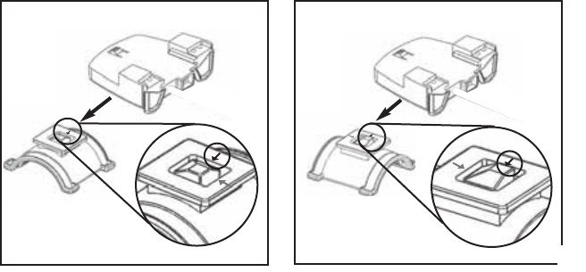
22..AAttttaacchh CCoommppuutteerr SShhooee ttoo HHaannddlleebbaarr oorr SStteemm
The shoe can be mounted on either the handlebar or stem. Secure the receiver shoe with cable
ties. Slide the receiver shoe in the direction of the arrow as depicted in either FIGURE 2A or 2B
depending on mounting location.
Receiver Shoe
Mounting Base
Arrow
Receiver Shoe
Mounting Base
Arrow
Slide shoe in direction of arrow onto the base.
Slide shoe in direction of arrow onto the base.
22AA..AAttttaacchh RReecceeiivveerr mmoouunntt ttoo HHaannddlleebbaarr22BB..AAttttaacchh RReecceeiivveerr mmoouunntt ttoo SStteemm
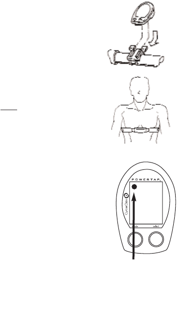
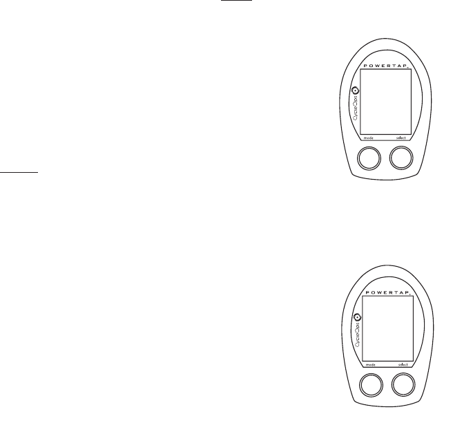
33.. PPllaaccee CCoommppuutteerr iinnttoo SShhooee
Place the computer into the mounting shoe on the handlebar or stem.
Line up the slots on the base of the computer with the bracket and slide
computer toward the rider (FIGURE 5). NOTE: Ensure the computer is fully
inserted onto the receiver shoe for proper data transmission.
44 HHeeaarrtt RRaattee MMoonniittoorr SSttrraapp
Position the heart rate monitor strap on your torso as pictured in FIG-
URE 6. The strap should rest just beneath the pectoralis muscles of
the chest. For best results slightly moisten the electrodes where con-
tact is made with skin. The heart rate strap mmuussttbe worn to enable
the heart rate function. NOTE:The chest strap for the PowerTap SL2.4
uses a coded frequency and is not compatible with other manufactur-
er’s chest straps.
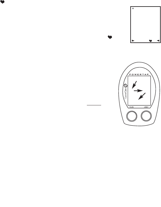
55.. VVeerriiffyy IInnssttaallllaattiioonn
Check to make sure all components are properly secured. Spin the
rear wheel and verify that in the upper left hand corner of the com-
puter the transmission icon illuminates (FIGURE 7). This indicates
the hub is properly transmitting a signal to the receiver and com-
puter. If the transmission icon is not illuminated consult Finding
Section Sensors for further instructions.
10
FIGURE 5
FIGURE 6
FIGURE 7
365
25
58.I0
WATTS3
MI
D
2.4
General Computer Operation
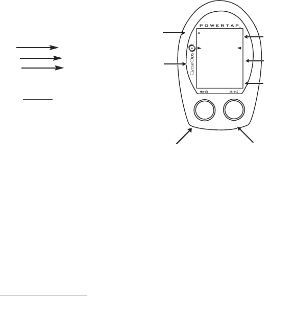
DDIISSPPLLAAYY LLEEVVEELLSS
The computer has three (3) main display levels:
Top Power
Middle Speed
Bottom Multi-Function
NOTE:These locations only apply to trip and
interval modes and ddooeess nnoottapply to Cycle Computer
or Heart Rate Monitor Function. See COMPUTER SETUP 4
to customize display options.
DDIISSPPLLAAYY MMOODDEESS
The computer has two (2) main modes of operation:
1) Trip
2) Interval
Hold [MODE] to toggle between display modes.
BBUUTTTTOONNSS
There are two (2) buttons on the computer:
1) [Mode]
2) [Select]
NOTE: [BRACKETED] words indicate buttons.
There are five (5) types of button presses:
1) Press [MODE] or [SELECT] - a single press and release of either [MODE] or [SELECT].
Used for entering different modes and functionality.
11
TTRRAANNSS..
IICCOONN
IINNTTEERRVVAALL
DDIISSPPLLAAYY
MMOODDEE((LLEEFFTT))
PPOOWWEERR
DDIISSPPLLAAYY
SSPPEEEEDD
DDIISSPPLLAAYY
MMUULLTTII
DDIISSPPLLAAYY
BBOOTTHHSSEELLEECCTT((RRIIGGHHTT))
Changes active
mode Clear data
Enter setup Select function

2) Hold [MODE] or [SELECT] - a single button press and hold of either [MODE] or
[SELECT] for 2 sec. Used for initiating a new Interval.
3) Press [MODE] and [SELECT] - simultaneously press and release of bbootthh[MODE] and
[SELECT].
4) Hold [MODE] and [SELECT] - simultaneously press and hold bbootthh[MODE] and
[SELECT] for 2 sec. NOTE: Continuing to hold longer than 2 sec. and releasing will clear
all data.
5) Extended Hold [MODE] and [SELECT] - simultaneously press and hold of bbootthh
[MODE] and [SELECT] for ggrreeaatteerr tthhaann 55 sseecc. Used for initiating scrolling menu.
SSCCRROOLLLLIINNGG MMEENNUU::
PPOOWWEERR CCOONNSSEERRVVAATTIIOONN
The computer and hub have power saving features to prolong battery life.The computer powers
down the display after four (4) minutes of inactivity.Press either [MODE] or [SELECT] to activate
the display.Similarly,the hub powers down after five (5) minutes of inactivity. The transmission
icon will not be visible when the hub is asleep.To wake the hub spin the wheel and verify the
transmission icon is illuminated. 12
SSCCRROOLLLLIINNGG MMEENNUU::
FFiinndd::
If [MODE] and [SELECT] are released
When “Find” is displayed the computer will find
Search for the PowerTap hub.
ccllrr::
If [MODE] and [SELECT] are released when
clr is displayed
AALLLL DDAATTAA WWIILLLL BBEE EERRAASSEEDD
.
SSEEtt::
If
[MODE] and [SELECT] are released
When SEt is displayed on the top level of the
Screen, a flashing “E”, d and t on the middle
Level and 12345 on the bottom level.
E = exit, return to ride mode
d = restore default settings
T = test mode
1 2 3 4 = setup menus

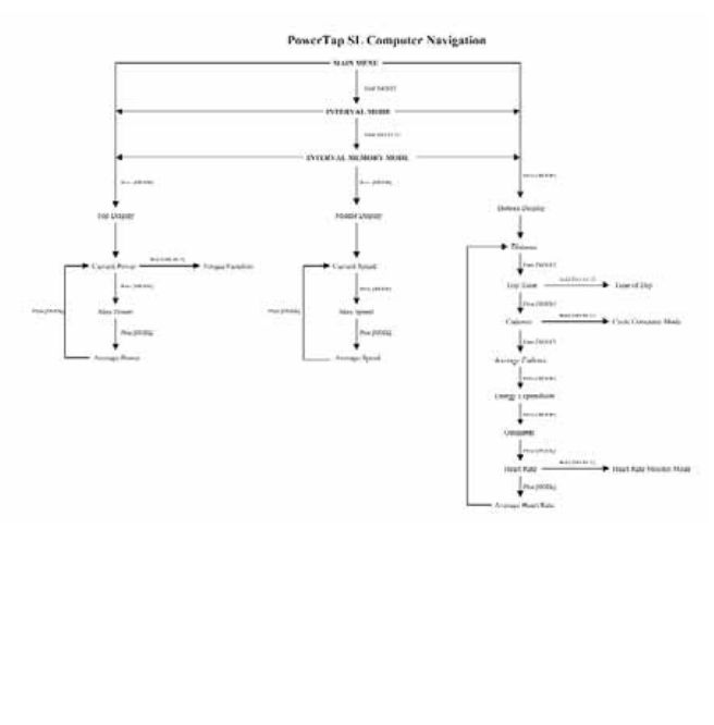
Computer Navigation
PPOOWWEERR FFUUNNCCTTIIOONN
The top level of the main display shows current,max,and average power readings.
1) Press [MODE] to scroll the cursor to the top line of the main display
2) Press [SELECT] to toggle through the power function options.
For accurate power readings it is important to ffrreeqquueennttllyyzero the torque,see ZERO TORQUE.
CCuurrrreenntt PPoowweerr
Power is displayed in watts from 0-1999 in 1 watt increments. Current power
readings are displayed only when the word “WATTS”appears below the top line
(FIGURE 9). NOTE:If “WATTS”ddooeess nnoottappear under the top line the computer is
in the Cycle Computer Function. To return to power readings see CYCLE
COMPUTER MODE.
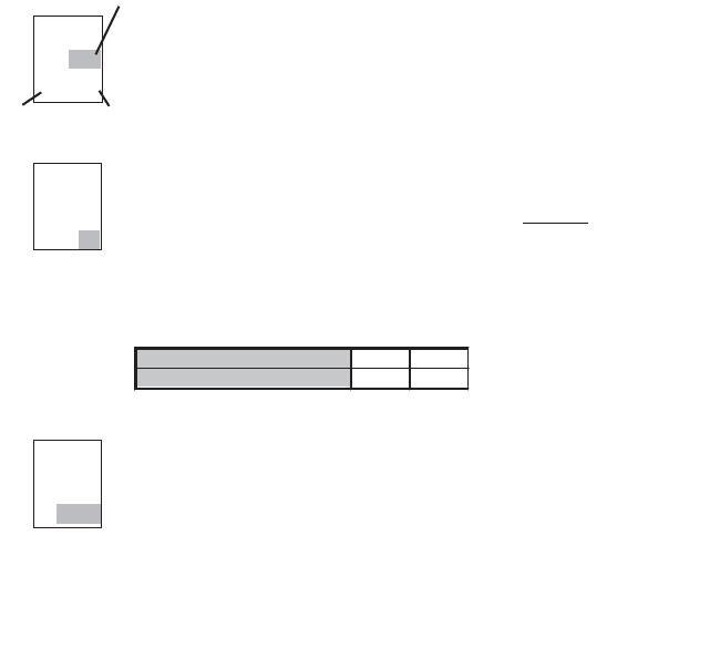
MMaaxxiimmuumm PPoowweerr
Both “WATTS”and “MX”displayed simultaneously indicate the highest recorded
power output since the last time the data was cleared in trip mode or the selected
interval in interval mode.(FIGURE 10)
AAvveerraaggee PPoowweerr
Both “WATTS”and “AVG”displayed simultaneously indicate the average power
output since the last time the data was cleared in trip mode or the selected
interval in interval mode.(FIGURE 11)
13
365
25
58.I0
WATTS3
MI
D
849
25
58.I0
MX WATTS
3
MI
D
I95
25
58.I0
3
MI
D
AV WATTS
FIGURE 9
FIGURE 10
FIGURE 11
TTOORRQQUUEE FFUUNNCCTTIIOONN
Shows the torque placed on the hub in inch-pounds. To display torque
in trip mode:
1) Press [MODE] to scroll the cursor to the top line of the main display.
2) Press [SELECT] until the current power function is displayed.
3) Hold [SELECT] until the word ‘WATTS”begins to flash. A blinking “WATTS”display indicates
the torque function is currently displayed.
4) Press [SELECT] to return to the current power function.(FIGURE 12).
3
MI
D
000
25
58.I0
IMPORTANT: ZERO TORQUE
Frequently the torque must be zeroed to ensure the most accurate power
information is displayed. If the current power display is positive or
negative while coasting the torque must be zeroed. This operations must
be done while coasting with no tension on the chain, no tension placed on
the pedals, and the transmission icon must be illuminated. To zero torque:
1) Press [MODE] to scroll the cursor to the top line of the main display.
2) Press [SELECT] until current power function is displayed.
3) Hold [SELECT] until the word “WATTS” begins to flash to enter the
torque function.
4) Hold [SELECT] again until “0” is shown.
5) Press [SELECT] to return to current power. The current power function
will now read zero while coasting.
14
FIGURE 12

SSPPEEEEDD FFUUNNCCTTIIOONN
The middle level of the main display shows current,max,and average speed readings.
1) Press [MODE] to scroll the cursor to the middle line of the main display.
2) Press [SELECT] to toggle through the speed function options.
CCuurrrreenntt SSppeeeedd
Speed is displayed in either miles per hour (MI) or kilometers per hour (KM) up to
99.9 mi/hr or km/hr in 0.1 mi/hr or km/hr increments. Current speed readings are
displayed when only “MI”or “KM”appears below the middle line.(FIGURE 13)
MMaaxxiimmuumm SSppeeeedd
Either “MI”or “KM”and “MX”displayed simultaneously indicate the highest record-
ed speed since the last time data was cleared in trip mode or the selected interval
in interval mode.(FIGURE 14)
AAvveerraaggee PPoowweerr
Either “MI” or “KM” and “AVG” displayed simultaneously indicate the average
recorded speed since the last time data was cleared in trip mode or the selected
interval in interval mode.(FIGURE 15)
15
365
25
58.I0
WATTS3
MI
D
365
33
58.I0
WATTS
7
MX MI
D
365
20
58.I0
3
AV MI
D
WATTS
FIGURE 13
FIGURE 14
FIGURE 15

MMUULLTTII--FFUUNNCCTTIIOONN DDIISSPPLLAAYY
DDiissttaannccee ((DD))
Total trip or the selected interval distance in interval mode is displayed in miles or
kilometers from 0.00 to 999.99 (FIGURE 16).
1) Press [MODE] to scroll the cursor to the bottom line of the main display.
2) Press [SELECT] to toggle through the multi-function displays until the “D”icon is displayed.
NOTE:Distance is displayed in the same units as speed.
TTrriipp TTiimmee aanndd TTiimmee ooff DDaayy ((TT))
Total trip time,interval time,and time of day is displayed to 9:59:59 (FIGURE 17).
1) Press [MODE] to scroll the cursor to the bottom line of the main display.
2) Press [SELECT] to toggle through the multi-function displays until the “T”icon is
displayed.
3) While in trip time hold [SLECET] to access the real time clock.
4) Hold [SELECT] to return to trip or interval time.
NOTE:Auto start and stop with rotation of the wheel is the default setting.To customize auto
start and stop see COMPUTER STETUP 4.
365
25
58.I0
WATTS3
MI
365
25
2.5 I.43
WATTS
3
MI
T
D
FIGURE 16
FIGURE 17

CCaaddeennccee ((CC))
Cadence is measured at the hub by analyzing the way a rider applies torque
through the pedal stroke since there are natural power differences in the pedal
stroke. The rate of pedaling is shown from 20 to 240 RPM.
NOTE:An optional wireless cadence sensor is available to measure cadence at
the crank.
1) Press [MODE] to scroll the cursor to the bottom line of the main display.
2) Press [SELECT] to toggle through the multi-function displays until the "C" icon is displayed.
(FIGURE 18)
17
365
25
89
WATTS3
MI
C
FIGURE 18
CCYYCCLLEE CCOOMMPPUUTTEERR MMOODDEE
Access to the Cycle Computer Mode is also gained in the cadence function.This fun-
tion allows the PowerTap SL2.4 computer to function as a cycle computer in the
absence of the PowerTap hub.This function is useful when the PowerTap SL2.4 hub is
not present such as in racing situations where lighter racing wheels are used.NOTE:In
Cycle Computer Mode heart rate is displayed in the top line of the main display and
power data is no longer displayed.To enter Cycle Computer Mode:
1) Press [MODE] to scroll the cursor to the bottom line of the main display.
2) Press [SELECT] to toggle through the mult-function displays until the “C”icon is dis-
played.
3) Hold [SELECT] and the word “WATTS”will disappear from below the top line.Place
magnet or rear wheel so it passes the receiver at the line or the sensor.
4) To return to current power function hold [SELECT] until the word “WATTS”is dis-
played under the top line of the main display.

AAvveerraaggee CCaaddeennccee ((CC && AAVVGG))
The average cadence displays data since the last time data was cleared in trip
mode or the selected interval in interval mode. Average cadence is displayed in
RPM.
1) Press [MODE] to scroll the cursor to the bottom line of the main display.
2) Press [SELECT] to toggle through the multi-function displays until the “C” and
“AVG”is displayed.(FIGURE 19)
EEnneerrggyy EExxppeennddiittuurree ((EE))
The total work done over the course of the trip or interval is shown in kilojoules.
This value is a measure of the total energy expended over the course of your ride.
This is roughly equivalent to dietary calories expended.
1) Press [MODE] to scroll the cursor to the bottom line of the main display.
2) Press [SELECT] to toggle through the multi-function displays until the “E”is dis-
played.(FIGURE 20)
OOddoommeetteerr ((OO))
Total accumulated distance traveled since the last system reset is displayed in
miles or kilometers. To manually input the your odometer reading see COMPUTER
SETUP 1.
1) Press [MODE] to scroll the cursor to the bottom line of the main display.
2) Press [SELECT] to toggle through the multi-function displays until the “O”
is displayed.(FIGURE 21)
18
365
25
76
WATTS
3
MI
C AV
365
25
2009
WATTS
3
MI
E
365
25
2584
WATTS3
MI
O
FIGURE 19
FIGURE 20
FIGURE 21

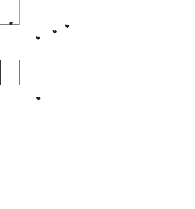
HHeeaarrtt RRaattee (())
Current heart rate is shown up to 255 beats per minute (BMP). You must wear the
heart rate chest strap to enable the heart rate measurement function. NOTE:The
PowerTap SL2.4 uses a coded chest strap.
1) Press [MODE] to scroll the cursor to the bottom line of the main display.
2) Press [SELECT] to toggle through the multi-function displays until the “ ”is
displayed.(FIGURE 22)
19
365
25
I72
WATTS
3
MI
HEART RATE MONITOR MODE
Access to the Heart Rate Monitor Mode is also gained in the current heart
rate mode. This function allows the PowerTap computer to function as a
heart rate monitor in the absence of the PowerTap hub. NOTE: In Heart
Rate Monitor Mode heart rate is displayed on the top line of the main
display and power data is no longer displayed.
1) Press [MODE] to scroll the cursor to the bottom line of the main display.
2) Press [SELECT] to toggle through the multi-function displays until the
( ) icon is displayed.
3) Hold [SELECT] and the words “watts” disappears from below the top
line.
4)To return normal PowerTap functions hold [SELECT] until the word
“WATTS” is displayed under the top line of the main display.
FIGURE 22
AAvveerraaggee HHeeaarrtt RRaattee ((AAVV))
This value is a running average of the heart rate in BPM. If there is no heart rate
information this will display as 0.
1) Press [MODE] to scroll the cursor to the bottom line of the main display.
2) Press [SELECT] to toggle through the multi-function displays until the “ AAVV”is
displayed.(FIGURE 23)
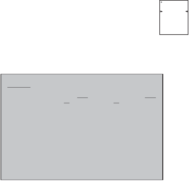
IINNTTEERRVVAALL MMOODDEE
The computer has two display modes. The trip mode shows total trip met-
rics,and the interval mode displays interval specific information.The inter-
val mode functions as a lap marker and is essentially always on.
To begin the first interval,or advance to the next interval:
Press and release [MODE] and [SELECT] simultaneously. NNOOTTEE:: DDoo nnootthhoolldd
bbootthh bbuuttttoonnss ddoowwnn aass yyoouu wwiillll cclleeaarr aallll ddaattaa ffrroomm tthhee ccoommppuutteerr..
In trip mode “INT” and the new interval number will appear and disappear
(FIGURE 24). The computer can mark an unlimited number of intervals
although after nine (9) the marker will begin to count back at one (1). For
example, interval ten (10) is displayed following interval (9) as one (1).
To view interval specific data (power, speed, and multi-function display) from any location on the
display:
1) Hold [MODE] until “INT”appears on the left hand side of the display. The “INT”and interval
number will remain illumined as a forth line in the main display (FIGURE 24). The data displayed
is that of the current interval number shown.
2)To exit back out of interval mode hold [MODE] until “INT”disappears. 20
365
25
152
WATTS
3
MI
AV
watts
speed
int
multi
FIGURE 23
FIGURE 24

IINNTTEERRVVAALL MMEEMMOORRYY MMOODDEE
To access stored interval data for the pprreevviioouuss 99 iinntteerrvvaallss oonnllyy:
1) Enter the interval mode hold [MODE] until “INT”appears on the left hand side of the display.
2) Press [MODE] to scroll until the “INT”flashes. NOTE:INT now constitutes a fourth level of dis-
play.
3) Hold [SELECT] and the memory icon (”M”) appears next to the interval number (FIGURE 25).
4) With “INT”flashing,press [SELECT] to advance to the interval you wish to view.
5) Press [MODE] scroll the cursor to the line of information you wish to view. NOTE:Recovery
periods as well as work periods are displayed in memory mode.
To exit back out of the interval memory mode hold [SELECT] until the memory icon disappears.
The computer is now displayed in the interval mode. To exit from the interval mode from any
location on the display hold [MODE] until “INT”disappears.
21
watts
speed
int m
multi
FIGURE 25
Computer Setup
The setup feature has four (4) main modes. You ddoo nnootthave to complete all four to change set-
tings. Please reference each mode to determine the correct location to begin. NNOOTTEE:: TThhee ccoomm--
ppuutteerr iilllluussttrraattiioonnss ffoorr eeaacchh mmooddee ddiissppllaayy tthhee ffaaccttoorryy ddeeffaauulltt sseettttiinnggss..
CCOOMMPPUUTTEERR SSE
ETTUUPP MMAAIINN MMEENNUU
1) Press either [MODE] or [SELECT] to activate the computer.
NOTE:The version of firmware is displayed upon startup. The most
updated firmware version is available at www.cycleops.com.(FIGURE
26)
2) Extended hold of [MODE] and [SELECT] simultaneously enters com-
puter setup function indicates by a flashing “E”. NOTE:Continue to hold
tthhrroouugghh“clear all”screen. Releasing hold early will clear all current data.
3) The setup mode displays three (3) letters and numbers 1-4. Each letter represents a setup
menu. A flashing alphanumeric character indicated current selection.(FIGURE 27)
E = exit,return to ride mode
d = restore default settings
T = test mode
1 2 3 4 5= setup menus
4) Press [SELECT] to scroll to the desired setup mode.
5) Press [MODE] to begin setup.
22
Set
E
12345
t
d
FIGURE 27
Set
12345
FIGURE 26

CCOOMMPPUUTTEERR SSEETTUUPP 11
This setup menu includes:time of day,date,storage rate,wheel circumference, units of measure,
odometer. NOTE:You are unable to move back to a previously viewed settings. You must restart
setup 1 to make corrections. You may hold [MODE] and [SELECT] to save and exit setup.
1) From the computer setup main menu press [SELECT] and scroll until the
number one (1) is flashing.Press [MODE] to enter setup mode.
2) Press [SELECT] to toggle between a 12 or 24 hour clock. Press [MODE] to
save.
3) Press [SELECT] to toggle between AM (A) or PM (P). Press [MODE] to
save.
4) Press [SELECT] to toggle through digit values to set hours in time of day.
Press [MODE] to save.
23
Std
t
12
Std
t
Std
p
t
12:00
p
Set
E
11234
t
d
5) Press [SELECT] to toggle through digit values to set minutes in time of
day. Press [MODE] to save.
6) Press [SELECT] to toggle through digit values to set year,month,and
date. Press [MODE] to save.
7) Press [SELECT] to toggle through storage rate values (1,2 seconds).
Press [MODE] to save. NOTE:Different storage rates yield different amounts
of total storage time. Changes to the storage rate ddooeess nnootteffect display
information. Refer to TABLE 3 for appropriate storage rate.
TABLE 3 - PowerTap SL2.4 Storage Rate
8) Press [SELECT] to toggle through digit values to set the wheel circumfer-
ence. Press [MODE] to save. Refer to TABLE 4 for common tire information.
NOTE: For the most accurate reading perform a roll out measurement
(mm) of the rear wheel.
24
Recording Rate (sec)
1
2
Max Recording Time (hrs)
15
30
Std
03
01-01
c
Year
Day
Month
Std
rec
1
Std
1CI
r
2096

TABLE 4 - Common Wheel Circumferences
9) Press [SELECT] to toggle between English or Metric units.
Press [MODE] to save.
10) Press [SELECT] to set starting odometer reading. Press [MODE] to save.
NOTE:Odometer settings are saved during battery changes.
25
Tire Size
Circ. (mm)
Tire Size
Circ (mm)
24 x 1
1753
27 x 1 1/4
2152
26 x 1
1913
700C Tubular
2094
26 x 1.25
1953
700 x 20C
2084
26 x 1.5
1986
700 x 23C
2096
26 x 2.0
2055
700 x 25C
2108
26 x 2.125
2070
700 x 28C
2116
27 x 1
2125
700 x 32C
2136
27 x 1 1/8
2139
700 x 38C
2170
Std
1
Std
1
00000
OD
o
mi

CCOOMMPPUUTTEERR SSEETTUUPP 22
This setup menu includes:rate of display for watts,speed,and cadence. NOTE:You are unable to
move back to a previously viewed settings. You must restart setup 2 to make corrections. NOTE:
These settings ddoo nnootteffect the data stored for download.
This function can be used to allow better pacing during time trial efforts. A greater rate of dis-
play allows for a slower update of the display.
1) From the computer setup main menu press [SELECT] and scroll until the
number two (2) is flashing and press [MODE] to enter setup mode.
2) Press [SELECT] to toggle through (1,2,3,5 10,30) rate of display values in
seconds for watts.Press [MODE] to save.
3) Press [SELECT] to toggle between (1,2,3,5 10,30) rate of display values
in seconds for speed.Press [MODE] to save.
4) Press [SELECT] to toggle between (1,2,3,5 10,30) rate of display values
in seconds for cadence.Press [MODE] to save.
6) Press [SELECT] then [MODE] to reset default settings. Press [MODE] to
save changes.
26
PRO
2
2
AV WATTS
PRO
2
3
AV MI
PRO
25
C AV
Set
E
12234
t
d

CCOOMMPPUUTTEERR SSEETTUUPP 33
This setup menu includes:zero readings for power,speed,and cadence. NOTE:You are unable to
move back to a previously viewed setting. You must restart setup 3 to make corrections. NOTE:
These settings are useful for determining you average when pedaling only and ddoo nnootteffect the
data that is stored for download.
1) Press [SELECT] to toggle between yes and no for zeros included in aver-
age of watts. Press [MODE] to save.
2) Press [SELECT] to toggle between yes and no for zeros included in aver-
age of speed. Press [MODE] to save.
3) Press [SELECT] to toggle between yes and no for zeros included in aver-
age of cadence. Press [MODE] to save.
4) Press [SELECT] to toggle between yes and no for auto-zero function.
NNoorrmmaallllyyleave at yes. NOTE:Auto-zero is used for track bike use where
large negative torque may be present. Hub modification to fixed hear is
necessary.
27
PRO
30’s
YES
AV WATTS
PRO
0’
s
AV MI
YES
PRO
3
c av
0’
s
YES
PRO
3
t
YES

CCOOMMPPUUTTEERR SSEETTUUPP 44
This setup menu includes:sleep time,locations of display,cadence source,cycle computer mode,
heart rate monitor,and auto start/stop. You are unable to move back to a previously viewed set-
tings. You must restart setup 4 to make corrections.
1) Press [SELECT] to set how many minutes the computer will stay “awake”
after not receiving a valid speed or heart rate signal. Press [MODE] to save.
NOTE:The shorter the sleep time the better the battery life.
2) Press [SELECT] to determine what is displayed in the middle line.(mi =
speed,c = cadence,( ) = heart rate). Press [MODE] to save.The selected
metric will flash during the ride. NOTE:If heart rate or cadence is selected
speed is not displayed. This is useful for intervals when power,heart rate
and cadence are most important.
3) Press [SELECT] to determine cadence information source.
Default = pedal then hub
Pedal = crank only
Hub = hub only
NOTE:An optional cadence sensor is available (sold separately).
Press [MODE] to save.
28
PRO
4
4
SLEEP
PRO
4
mi
PRO
4
pedal
c
Hu
P
4) The PowerTap can be used as a cycle computer or heart rate monitor.
Press [SELECT] to toggle through mode options.
watts,mi,and ( ) = power meter mode
mi,and ( ) = cycle computer mode
( ) = heart rate monitor mode
Press [MODE] to save.
5) Press [SELECT] to toggle through auto start options.
mi,and data = allows trip time to count when wheel speed is registering.
Trip time stops 3 sec.after if speed is not registered.
( ),and data = allows trip time to count as long as a heart rate signal is
registered. This function is useful in the transition from cycling to running
and vice versa.
Press [MODE] to save.
29
PRO
4
mi
watts
PRO
4
mi
watts
data

CCOOMMPPUUTTEERR SSEETTUUPP 55
This setup allows the CPU to learn a new device or sensor such as the hub,heart rate strap and
optional cadence sensor. NOTE:This process only needs to be used if a new sensor or hub is
being used in conjunction with your CPU or vice versa and if batteries are changed in the hub or
chest strap. There are 2 Learn sequences,1 and 2. Learn 1 is used when you have switched sen-
sors or the CPU and there are no other like bikes with PowerTap SL2.4 within a 30’radius. Learn 2
is used if there are other devices in the area but requires you to remove and reinsert the battery
before activating the Learn 2 sequence.
1) To manually change the hub I.D.Push [Select] to toggle through the
Hub I.D.Press [Mode] to save.
2) In most cases the Hub I.D.will not be known so you can "learn" the I.D.by
pressing [Mode] to advance through the Hub I.D.settings to Learn 1. NOTE:
Learn 1 will search for any active hub so be sure that there are no other
active hubs in the area. If there are,proceed to Learn 2.
3) Learn 1 is initiated by Holding [Select] until "Learn" begins flashing.
When the CPU has learned the device I.D.it will display the I.D.
Press [Mode] to advance to the next device I.D. If it did not learn the device
it will take you back to the most recent Hub I.D. NOTE:Make sure the hub is
"awake" by spinning the wheel or axle.
4) Press [Mode] until Learn 2 is displayed. Learn 2 is used when there are
other "awake" or active PowerTap SL 2.4 hubs within a 30 foot radius.
5) Initiate Learn 2 by first removing the batteries from the hub for 5
seconds and replacing them.Then hold [Select] until "Learn" begins to
flash. When the CPU has learned the hub I.D.it will display the I.D.
Press [Mode] to save and proceed to the next device I.D.If it did not learn
the device it will take you back to the most recent Hub I.D. 30
hub
Id
45847
hub
Id
LEArn
1
hub
Id
LEArn
1
flashing
hub
Id
LEArn
2
hub
Id
LEArn
2
flashing

6) Follow the above steps for any additional sensors you may be using,
such as the heart rate strap,speed and cadence sensors.
SPd = speed sensor
Cd = cadence sensor
HS = heart rate sensor
31

Maintenance & Specifications
The following information will help you keep your PowerTap SL2.4 running properly.If you are
not familiar with hub maintenance please consult a professional
bicycle mechanic before servicing.
DDuurriinngg tthhee ccoouurrssee ooff aannyy rreeppaaiirr ddoo nnoott rreemmoovvee tthhee ttoorrqquuee ttuubbee.. TThheerree aarree nnoo uusseerr sseerrvviicceeaabbllee
ppaarrttss iinnssiiddee.. SSppeecciiaall ttoooollss aarree rreeqquuiirreedd ffoorr rre
eaasssseemmbbllyy aanndd ccaalliibbrraattiioonn.. IIff pprroobblleemmss aarree ssuussppeecctteedd
ccoonnttaacctt SSaarriiss CCyycclliinngg GGrroouupp..
BBEEAARRIINNGGSS
The power measuring components inside the PowerTap SL2.4 are highly complex and should
only by serviced by Saris Cycling Group.The bearings are sealed type 6901RS and do not require
replacement.Field replacement can cause permanent damage to the power measuring electron-
ics and result in compromised sealing and performance.If bearing problems are suspected
please contact Saris Cycling Group at 1-800-783-7257 for a return authorization.The PowerTap
SL2.4 uses a modern 4 bearing design and does not require any tensioning adjustment.
FFRREEEEHHUUBB
The grease in the freehub pawls should be replaced if it becomes contaminated with water.
Replace the seal at the same time,contact Saris Cycling Group for replacement parts.Saris
Cycling Group recommends the following types of grease to ensure proper functioning:
-Kluber Isoflex NB52 o
-Dupont Krytox GPL226
Warning:Failure to use the proper grease on the freehub pawls could result in engagement
problems.
FFRREEEEHHUUBB RREEPPLLAACCEEMMEENNTT
-See Figure 28 for illustrations
-Use 5mm hex wrench and 17mm bike wrench and remove both end nuts from the axle.
-Remove the axle
-Remove the freehub and spacers.
-Remove all old grease from the freehub ratchet ring. 32

-Install spacers per the illustration.
-Install axle.
-Apply 2 grams of high quality freehub grease to the ratchet ring.
-Grease the V seal and place it on the freehub and install onto shaft.
-Replace end nuts.Torque end nuts to 12 lbs-ft.
33
FIGURE 28

CCOOMMPPUUTTEERR BBAATTTTEERRIIEESS
The PowerTap SL2.4 has batteries in the hub and computer.Computer bat-
teries typically need to be changed every 400 hours of use.The computer
will also say “low bat”when the computer battery needs to be changed.This
message is displayed after a “clr”is performed.To replace computer battery
(Type CR2032),remove the computer from the mount.Remove the battery
cover on the back of the computer (use a cone wrench to remove the bat-
tery cover),exchange the battery,and replace the cover as shown below
(FIGURE 29).
TTEECCHHNNIICCAALL SSPPEECCIIFFIICCAATTIIOONNSS
Accuracy +/-1.5%
Signal Transmission 2.4 Ghz
Interval Data Storage Unlimited
Interval Display 9 Intervals (internal recording)
Operational Temperature 0 to 40 degrees c or 32 to 104 f
Battery Life (Hub) 300 hours approx.
Battery Life (Console) 400 hours approx.
Battery Type (Hub) Type 357 or EPX 76 (2 ea)
Battery Type (CPU ER2032
RRAANNGGEE OOFF MMEEAASSUURREEMMEENNTT
Power 0-1999 Watts
Torque 0-1999 inch-lbs.
Speed 2-59 mph (3-95 KPH)
Distance 0.00 to 9999.99 (Miles)
Trip Time 0.00.00-999.99 Minutes
Cadence 40-140 RPM
Total energy 0-99999 Kilojoules
Odometer 0-99999 Miles or Kilometers
Heart Rate 0-255 BPM (Beats per Minute)
34
FIGURE 29

HHUUBB BBAATTTTEERRIIEESS
Normal battery life in the hub is 400 hours of actual ride time.Use #357 or EPX76 Silver Oxide
type batteries and always replace batteries in pairs.Alkaline type batteries give shorter life and
poorer performance.NOTE:After replacing batteries in the hub you need to Learn the device
codes.See computer setup 5.
BBAATTTTEERRYY RREEPPLLAACCEEMMEENNTT
- Unscrew the plastic battery cover.Use a spanner wrench or bench vise opened wide to get it
started if stuck.There are O-ring seals that can cause the cover to resist the start of motion.The
threading is normal right hand.
- Remove the battery pack.A small screw driver can be used back and forth between the to ends
to start to lift it out.
- Pop the battery out by bending the plastic retaining tap back and pushing the batter up from
the bottom.
- Check that the electrical connector tab from the inside of the hub is perpendicular to the
bottom of the battery pocket.If the tab gets bent,gently press it back to perpendicular with
a non-sharp tool.
-Slide the battery pack back into position along the center core.As the battery is engaged a small
increase of resistance to installation should be felt as the electrical connections are made.
- Thread the cap all the way back on.
- Replacement O-rings and battery packs are available from Saris Cycling Group.
35

TTEESSTT MMOODDEE
1) From the computer setup main menu press [SELECT] and scroll until the letter “t”is flashing.
Press [MODE] to enter setup mode.
2) Press [MODE] to scroll through the different test modes as shown by the number. NOTE:Press
and hold [MODE] and [SELECT] simultaneously returns to standard operation.
00 -- MMooddeell aanndd vveerrssiioonn..
Displays the model on the middle line and version number on the bottom line.
11 -- LLCCDD TTeesstt
Press [SELECT] all the LCD segments are displayed.Press [SELECT] to return to the normal screen.
22 -- HHeeaarrtt RRaattee SSiiggnnaall TTeesstt
NOTE:The heart rate signal is illuminated.
The middle line display flashes “88”with each heart rate blip received.
33-- TToorrqquuee IInnffoorrmmaatti
ioonn
NOTE:The T icon is displayed.
This displays information about the internal workings of the torque readings.The bottom display
is the offset torque value directly sent by the hub torque with no correction applied.The hub
sends a value of approximately 512 as the zero point.The middle line display is the correction
offset value currently stored in the computer.This is the value that is changed when you do a
manual zeroing of the torque.The top display is the corrected actual torque (the bottom value
minus the middle value).
44 -- SSttaannddaarrdd TTeesstt FFiillee
This mode writes a small test file to the memory.Press [SELECT] and the bottom lines says “run”
and then “yes”when the file is written.This file can then be downloaded.
55 -- CCoommmmuunniiccaattiioonn LLoooopp BBaacckk TTeesstt
When looking at the front side of the computer,use a coin or paper clip to short out the two pins
36

on the left side.Press [SELECT].The bottom line will say “run”and then “yes”if it passes the test
correctly.If the pins are not shorted together or there was a problem,the display will say “no”.This
test can be repeated by pressing [SELECT].
66 -- FFaasstt MMeemmoorryy TTeesstt
This tests the memory in the computer.Press [SELECT] and “run”is displayed on the bottom line.
When the test is completed and it passes,it says “yes”.If the test should fail,the bottom line will
say “no”.
37

Troubleshooting
NNoo ddiissppllaayy oonn ccoommppuutteerr ssccrreeeenn
· Computer is asleep – Press [MODE] or [SELECT] on the computer to wake up the computer.
· Batteries need replacement - replace the computer batteries as shown on pages 14-15 of the
User Manual.
· Computer is too cold- operating temp.is 32 to 110 degrees Fahrenheit
CCoommppuutteerr ddiissppllaayy iiss oonn,, bbuutt tthheerree iiss nnoo ttrraannssmmiissssiioonn iiccoonn
· Hub is asleep - spin the wheel to wake up the hub.
· Batteries need replacement - replace the hub batteries as shown on page 34 of the
User Manual.
· Does the word “watts”appear under the top line? If no than you have entered cycle computer
mode. See cycle computer mode for further instructions.
· Computer not seated in mount - make sure computer is firmly and correctly mounted in
handlebar mount.
· Moisture in hub - remove cover to see if there is any condensation on the battery cover.If there
is,leave cover off in a dry place for 12 hours or until moisture disappears.
· Interference with other devices - make sure you are not setting up the PowerTap inside a
building with a lot of electrical noise,neon signs,or near power lines.Bring the PowerTap out
side or away from the electrical disturbance to see if signal returns.Also make sure you don’t
have any other devices on your bike such as lights,magnets or cycle computer sensors.
· PowerTap computer’s batteries are low,replace batteries as shown on page 34 of the
User Manual.We recommend using a Cone Wrench to remove the battery cap,not a coin.
·· DDiissppllaayyeedd ddaattaa bblliinnkkss oorr ddooeess nnoott ffuunnccttiioonn
· Batteries need replacement - replace the computer batteries as shown on pages 34 of
the User Manual.
· Computer not seated in mount - make sure computer is firmly and correctly mounted in
handlebar mount.
· Interference with other devices - make sure you are not setting up the PowerTap inside a
building with a lot of electrical noise,neon signs,or near power lines.Bring the PowerTap
outside or away from the electrical disturbance to see if signal returns.Also make sure you don’t
have any other devices on your bike such as lights,magnets or cycle computer sensors. 38

PPoowweerr sseeeemmss iinnccoorrrreecctt
·Torque value is not zeroed to manually zero torque go to current watts and hold down the
select button until watts disappears.Torque is now being displayed.To zero torque hold down
the select button until the value reads zero.To exit torque mode press select once.If read zero
the torque does not seem to recalibrate the unit call Saris Cycling Group customer service at
1-800-783-7257.
SSppeeeedd sseeeemmss iinnccoorrrreecctt
· Wheel size incorrect -refer to the chart on page 25 and enter the correct size in setup mode.
TTrraannssmmiissssiioonn iiccoonn ffllaasshheess rraappiiddllyy
· Hub batteries need replacement - replace the hub batteries as shown on page 34 of
the User Manual.
Glossary
CCoommppuutteerr - Refers to the yellow handlebar or stem mounted device.
HHeeaarrtt RRaattee ((HHRR))- This displays current HR. Max and average values are displayed if [MAX] or
[AVG] is selected. NOTE:A non-coded chest strap must be used in order for the console to 39

pick up heart rate.
WWaattttss- Real-time display of the effort you are putting in to pedaling the bike. This is your power
reading. **If you press the [SELECT] while the cursor is pointing to Watts the line changes to
"inch-lbs". This is the raw torque value that is being applied to the hub,NOT your power in watts.
CCaaddeennccee ((CC))- The number of pedal revolutions per minute. The rate of pedaling is shown from 0
to 140 RPM.
SSppeeeedd- The estimated speed that you would be traveling on a flat road with no wind is displayed
here.
SSccrroollll= to move vertically through available menu or screen options
TTooggggllee= to move horizontally through alphanumeric digits
CCuurrssoorr = the ® arrow located on console screen
MMeettrriiccss= a standard of measurement
MMAAXX= Max
RRPPMM= Revolutions Per Minute
MMII = Miles Per Hour
KKMM= Kilometers Per Hour
UUII= User Interface
40
41
Saris Cycling Group,Inc.
5253 Verona Road
Madison,WI.53711
1-800-783-7257
16034D-2.4
Patents issued and pending.
Patent#6,418,797