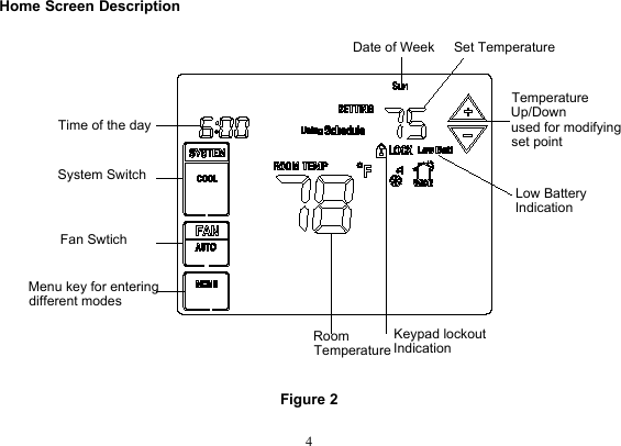
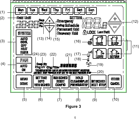
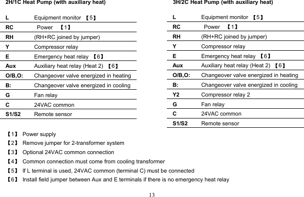
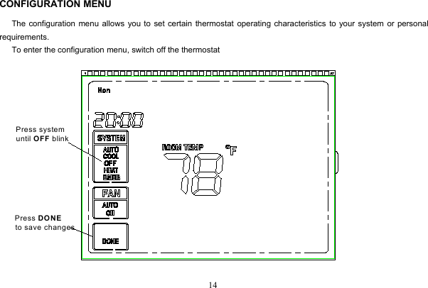
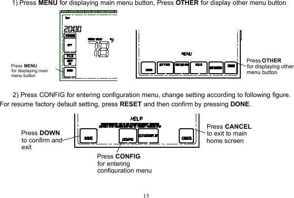
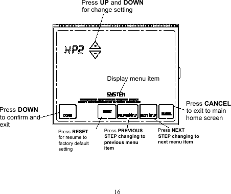
Saswell Technology and Development SAS6000UTK Room Thermostat User Manual
Shenzhen Saswell Technology&Development; Co., Ltd Room Thermostat
UserManual.wiki
>
Saswell Technology and Development
>
SAS6000UTK User Manual
User Manual
Navigation menu
Upload a User Manual
Namespaces
Wiki Guide
HTML
PDF
Info
Views
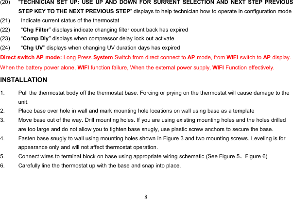
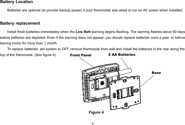
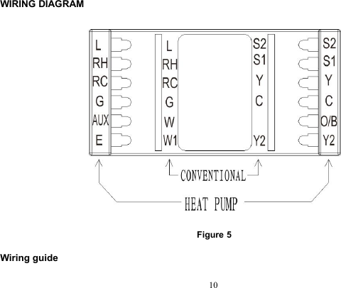
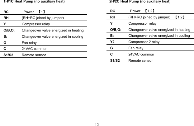
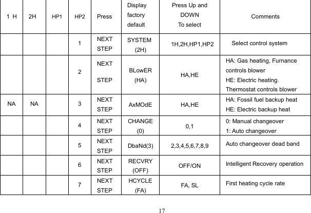
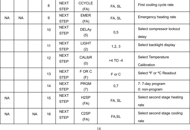
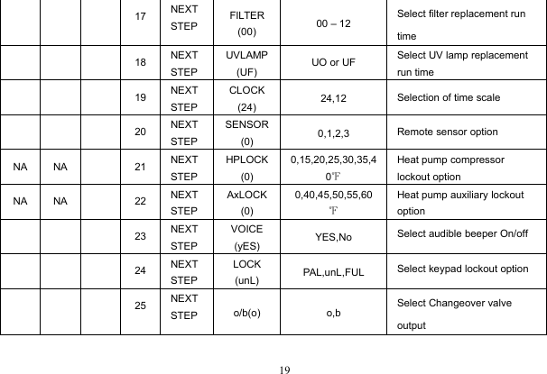
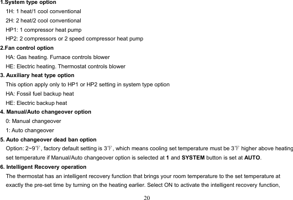
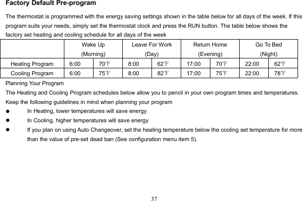
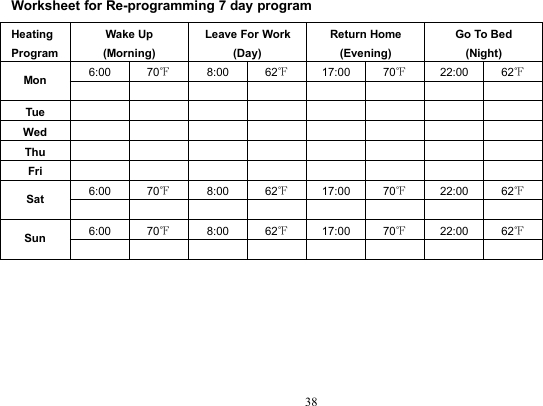
User Manual
Discussion / Help
Navigation