Satel SATEL-3AS-125 SATELLINE-3AS(d)/125 radio data modem User Manual of SATELLINE 3AS
Satel Oy SATELLINE-3AS(d)/125 radio data modem of SATELLINE 3AS
Satel >
Contents
- 1. User manual of SATELLINE 3AS
- 2. 3AS TC user guide
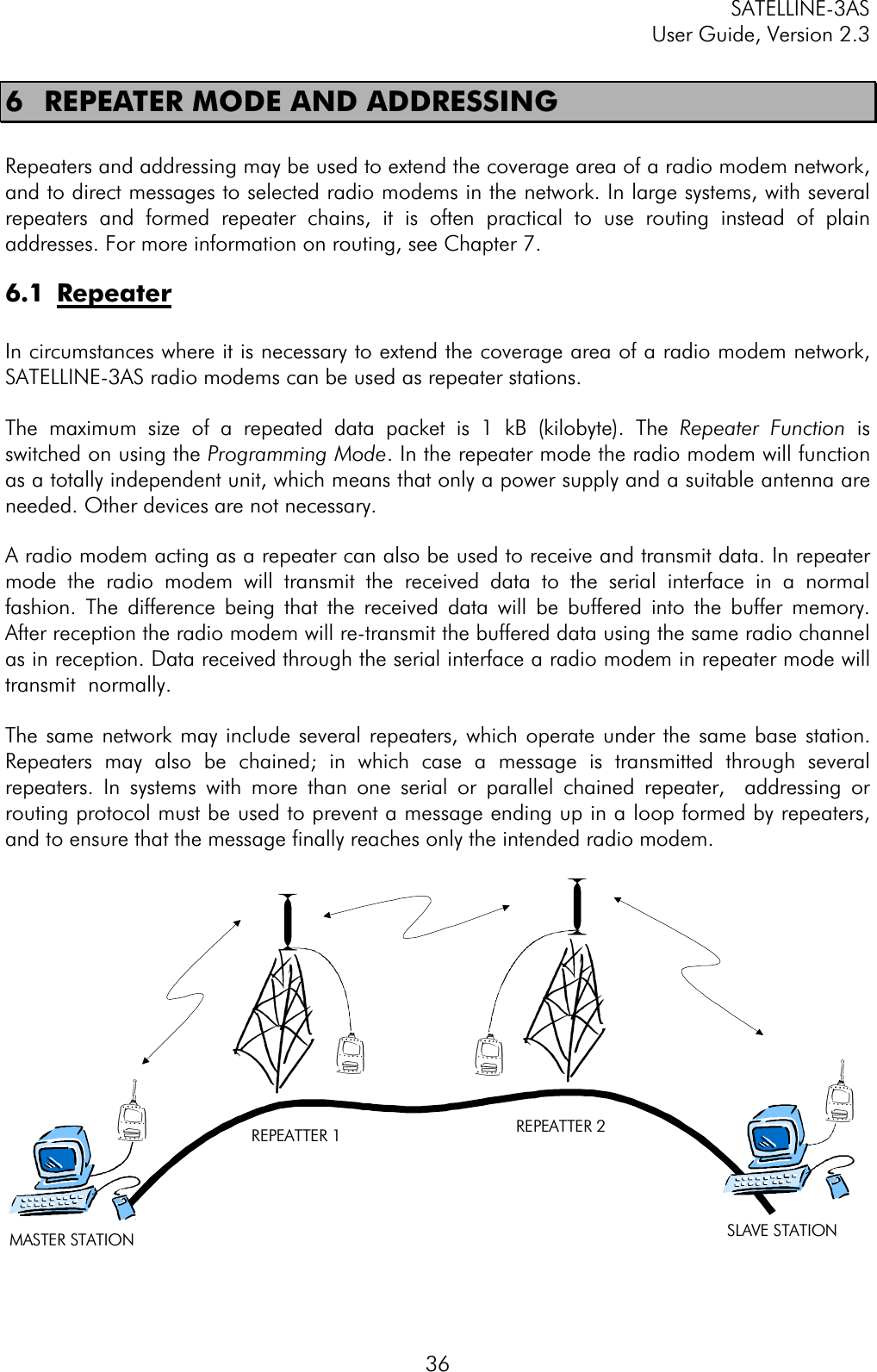
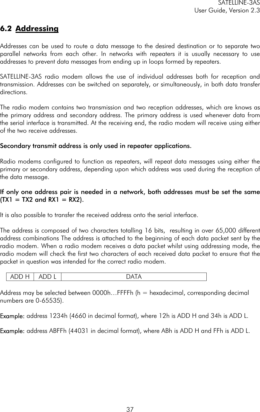
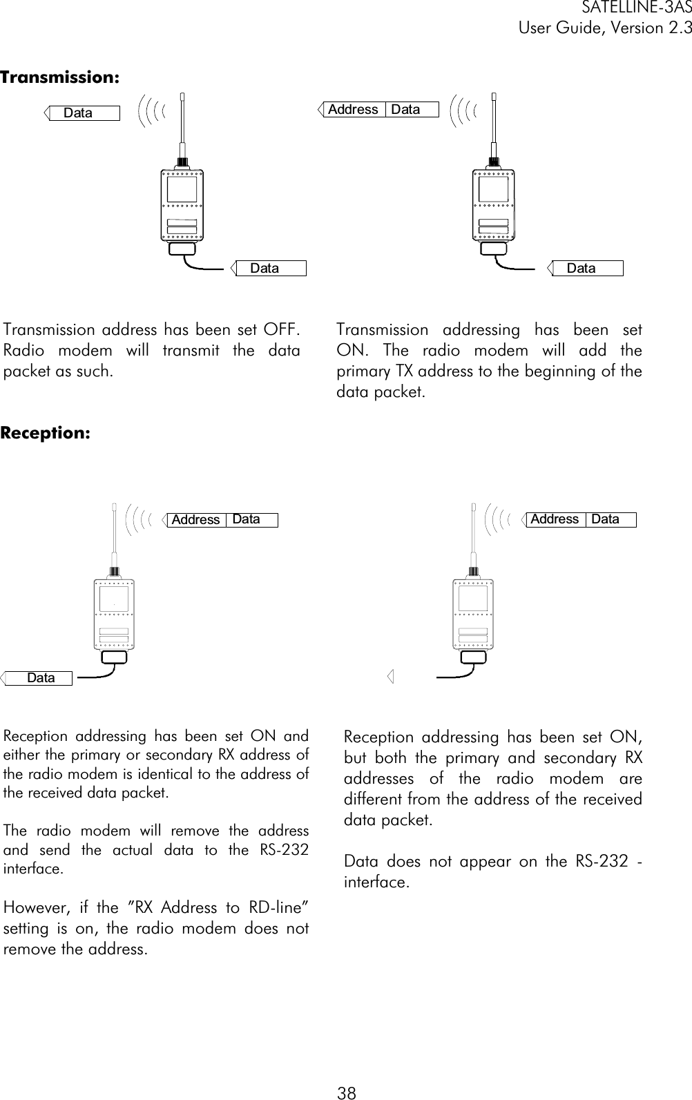
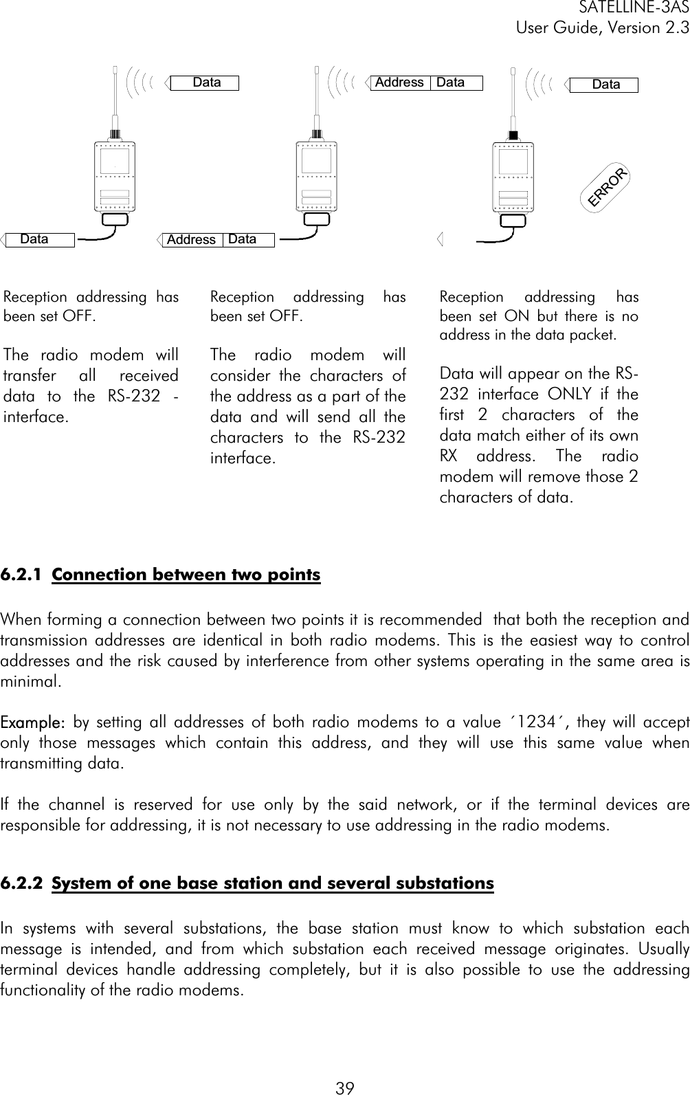
User manual of SATELLINE 3AS
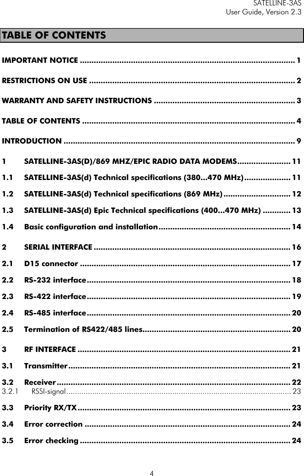
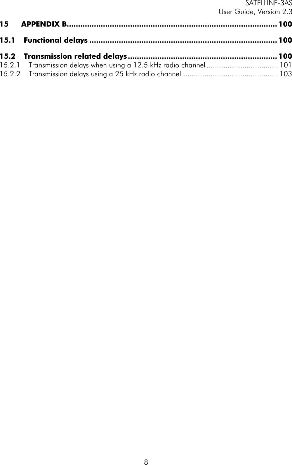
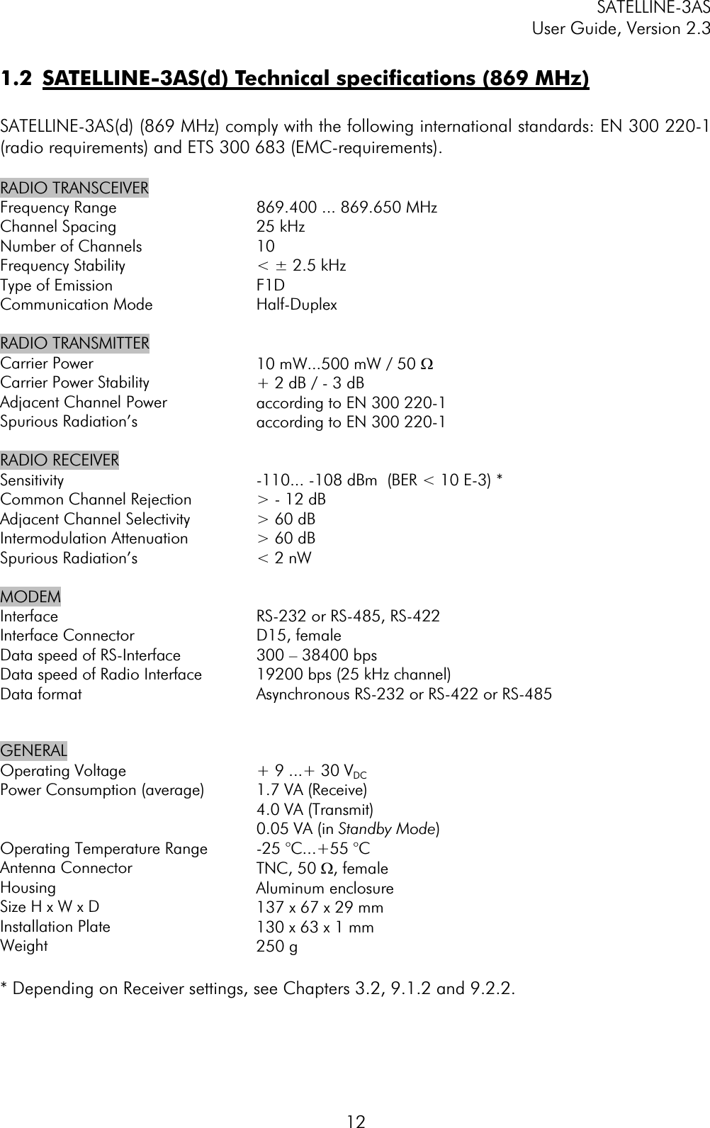
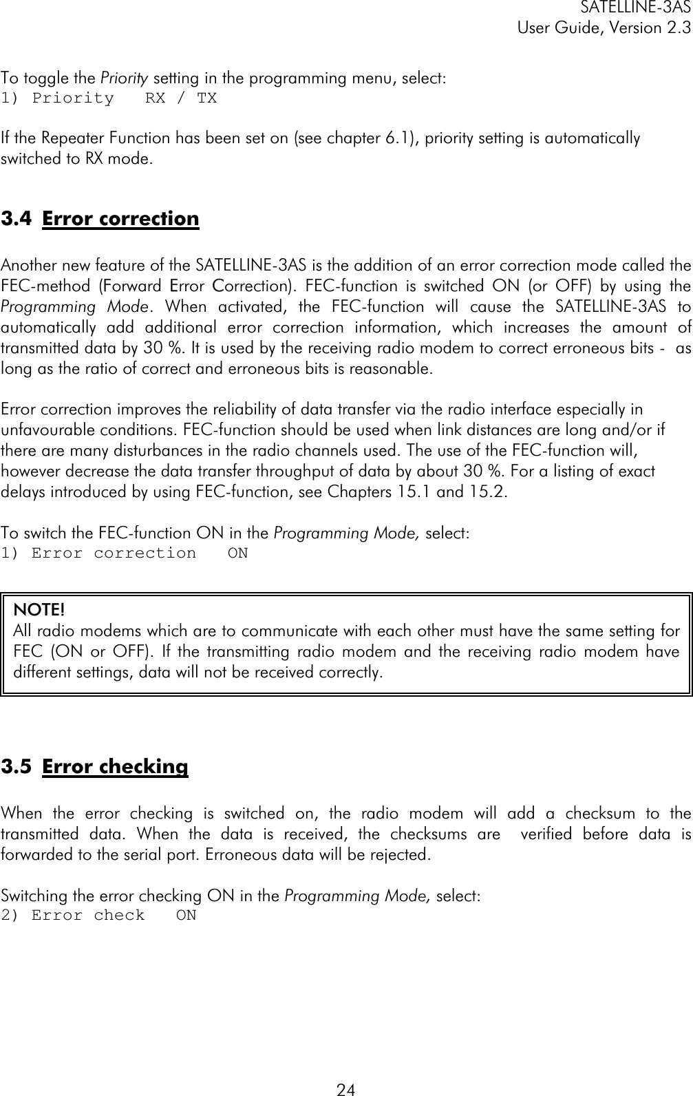
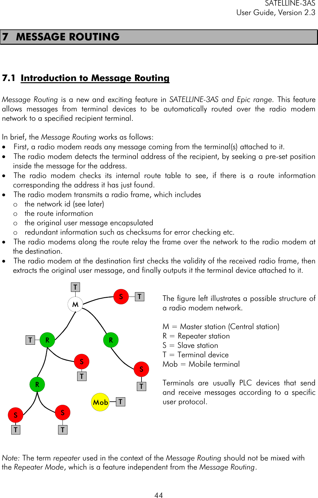
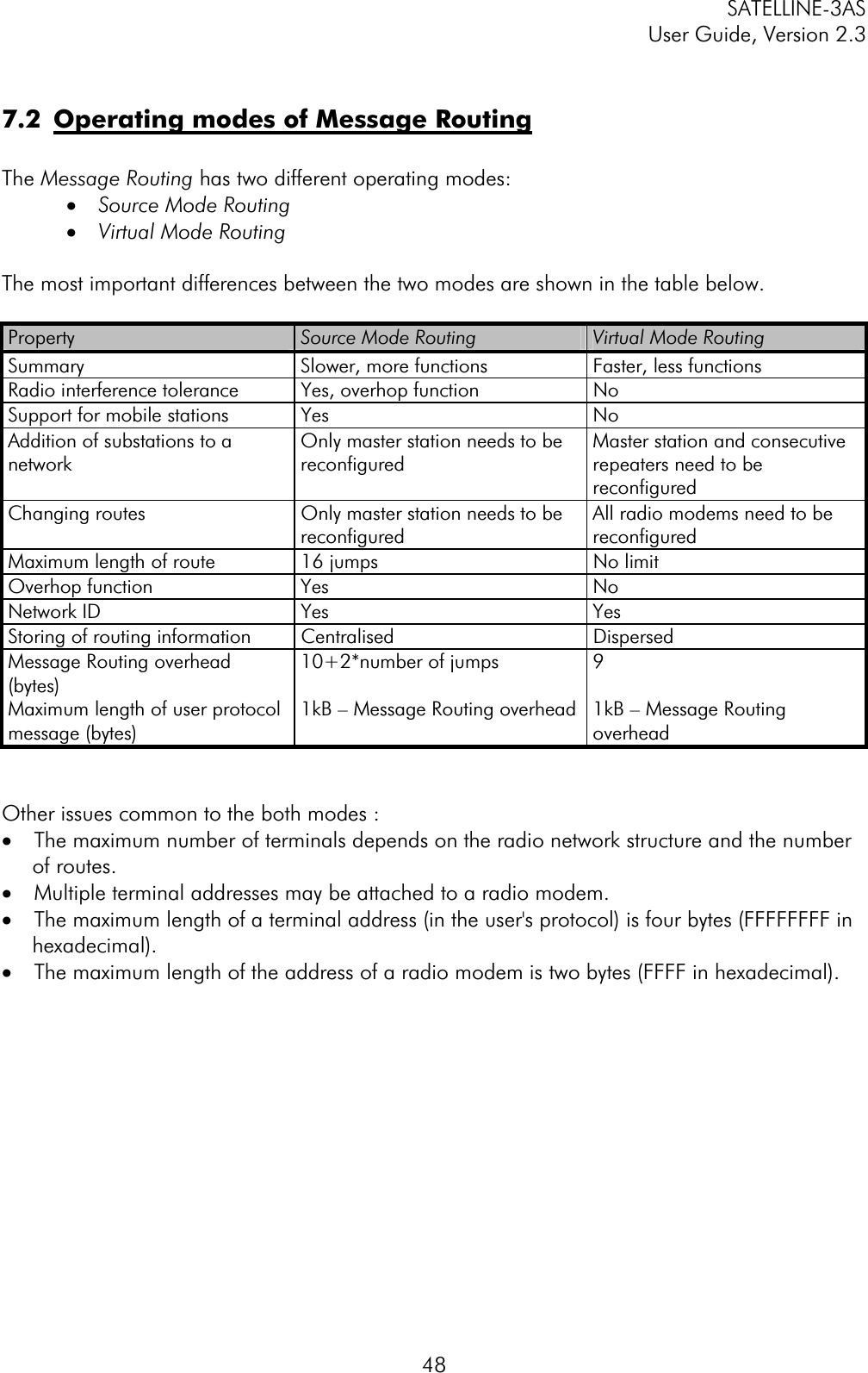
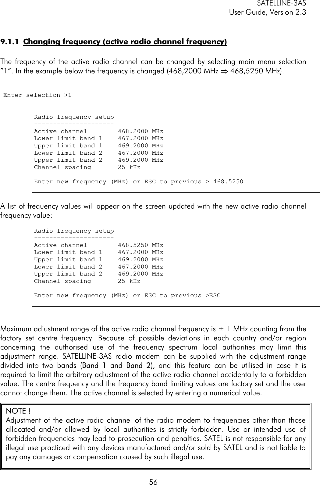
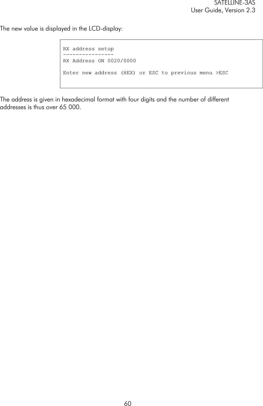
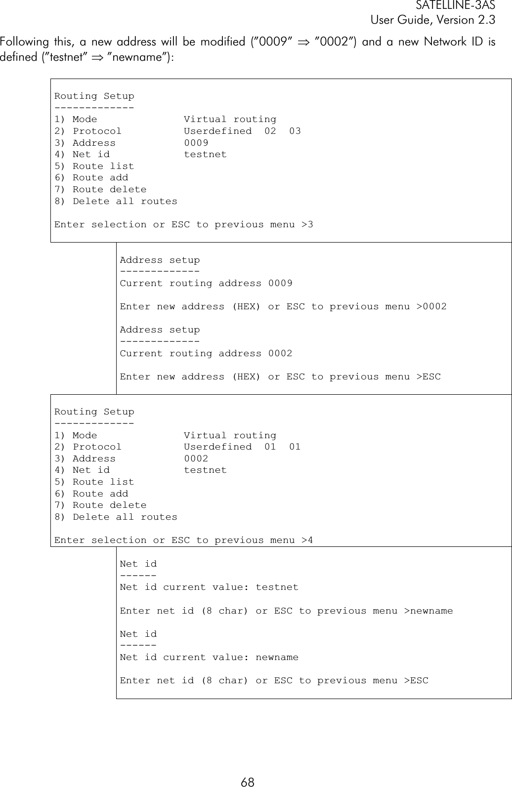
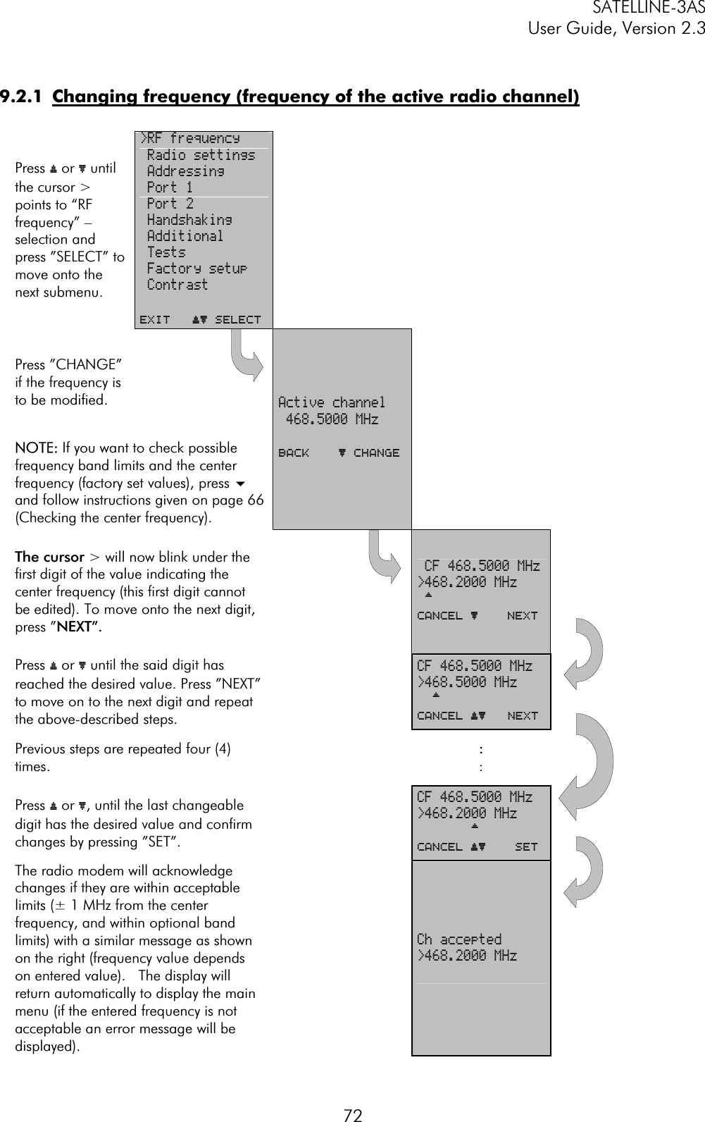
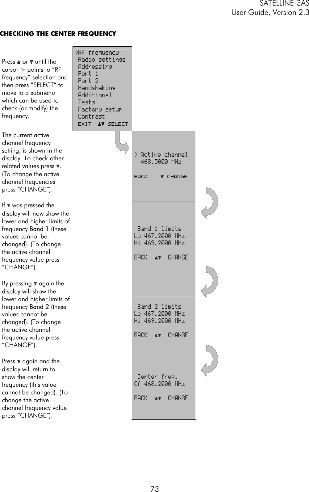
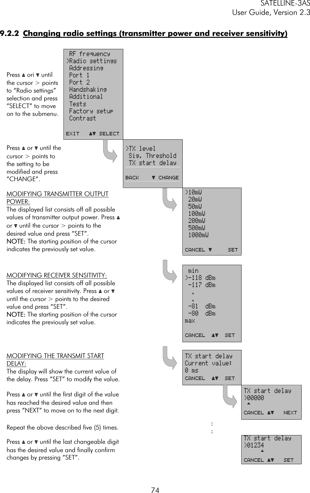
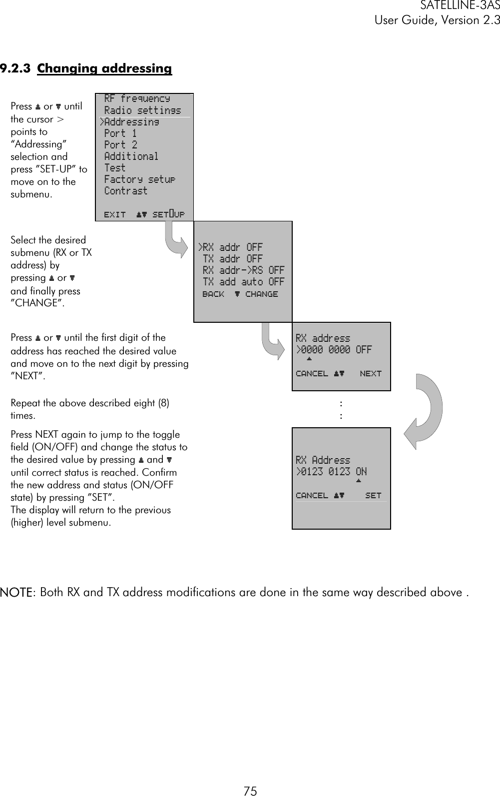
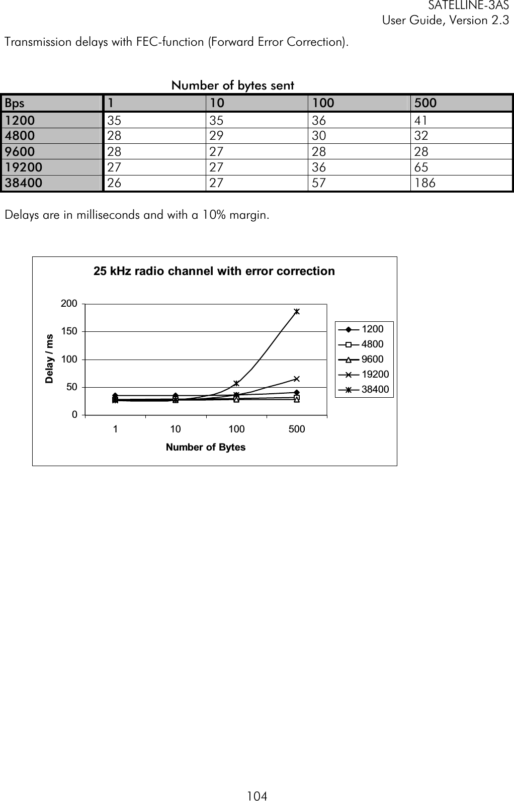
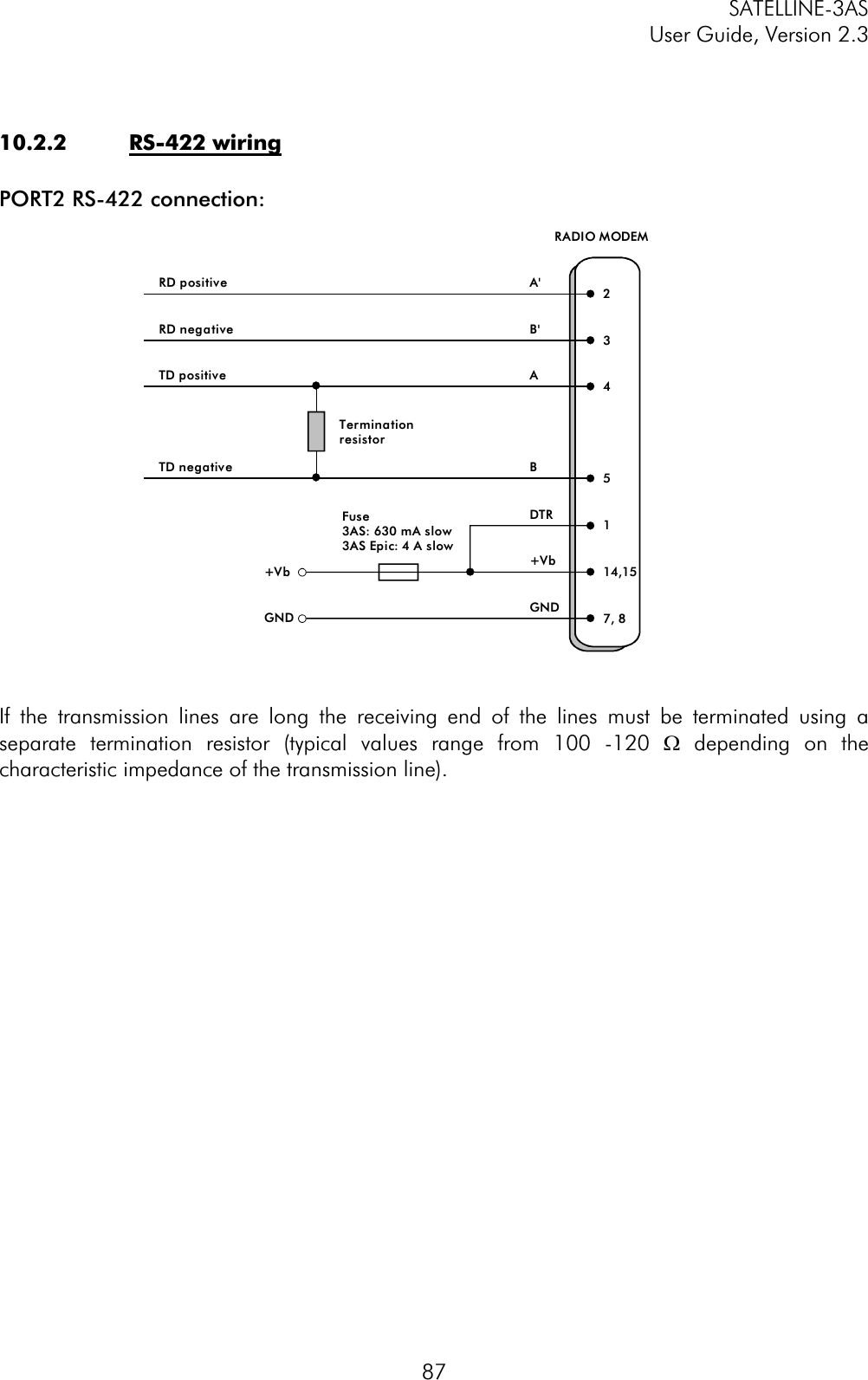
![SATELLINE-3AS User Guide, Version 2.3 81In case you need more information on the time delays related to the use of SL-commands, please contact the manufacturer. 9.3.1 FrequencyCommand Effect and description of command SL&F=nnn.nnnnn Set frequency to nnn.nnnnn MHz SL&F? Display current frequency (response 'nnn.nnnnn MHz') SL&C? Display center frequency (response 'nnn.nnnnn MHz') SL&+=nn Set frequency nn channels above center frequency Frequency = Center frequency + nn * Channel spacing, where nn=[0...Number of channels/2] SL&-=nn Set frequency nn channels below center frequency Frequency = Center frequency – nn * Channel spacing, where nn=[0…Number of channels/2] SL&N? Display current frequency deviation from center frequency as channels (Frequency – Center frequency)/Channel spacing (response ‘+nn’ or ‘-nn’) SL&D=x Sets the operational mode of the radio. The different values of x are: ”S” = Single Channel ”D” = Dual Channel ”R” = Reverse Dual Channel Note! Use this command only, if the setup of the frequency bands matches the Dual Channel operation. SL&D? Request the operational mode of the radio. The response is one of the following: ”S” = Single Channel ”D” = Dual Channel ”R” = Reverse Dual Channel Note! Use this command only, if the setup of the frequency bands matches the Dual Channel operation. 9.3.2 AddressingCommand Effect and description of command SL#I=xxxx Set all addresses (RX1, RX2, TX1, TX2) to value xxxx SL#I? Display both primary addresses (TX1, RX1) (response ’xxxx;yyyy’) SL#T=xxxx Set both transmit addresses (TX1, TX2) to value xxxx SL#T? Display primary transmit address (TX1) (response ‘xxxx’) SL#R=xxxx Set both receive addresses (RX1, RX2) to value xxxx SL#R? Display primary receive address (RX1) (response ‘xxxx’) SL#P=xxxx;yyyy Set primary transmit address (TX1) to value xxxx and receive address (RX1) to value yyyy](https://usermanual.wiki/Satel/SATEL-3AS-125.User-manual-of-SATELLINE-3AS/User-Guide-327507-Page-81.png)
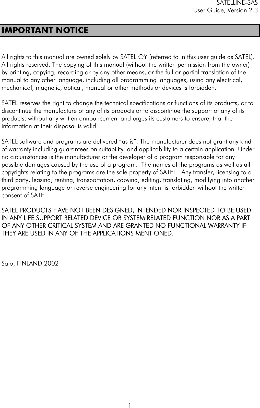
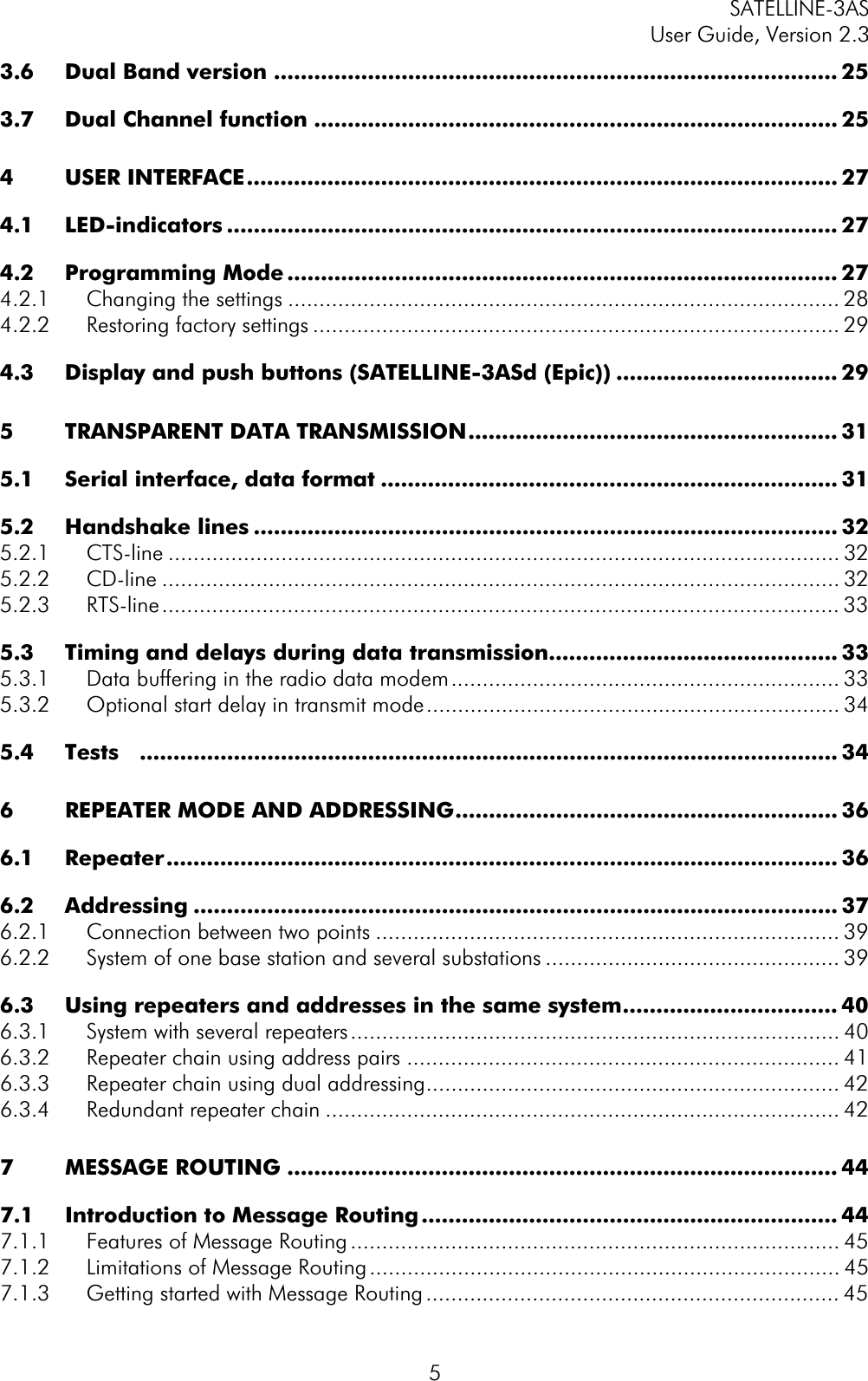
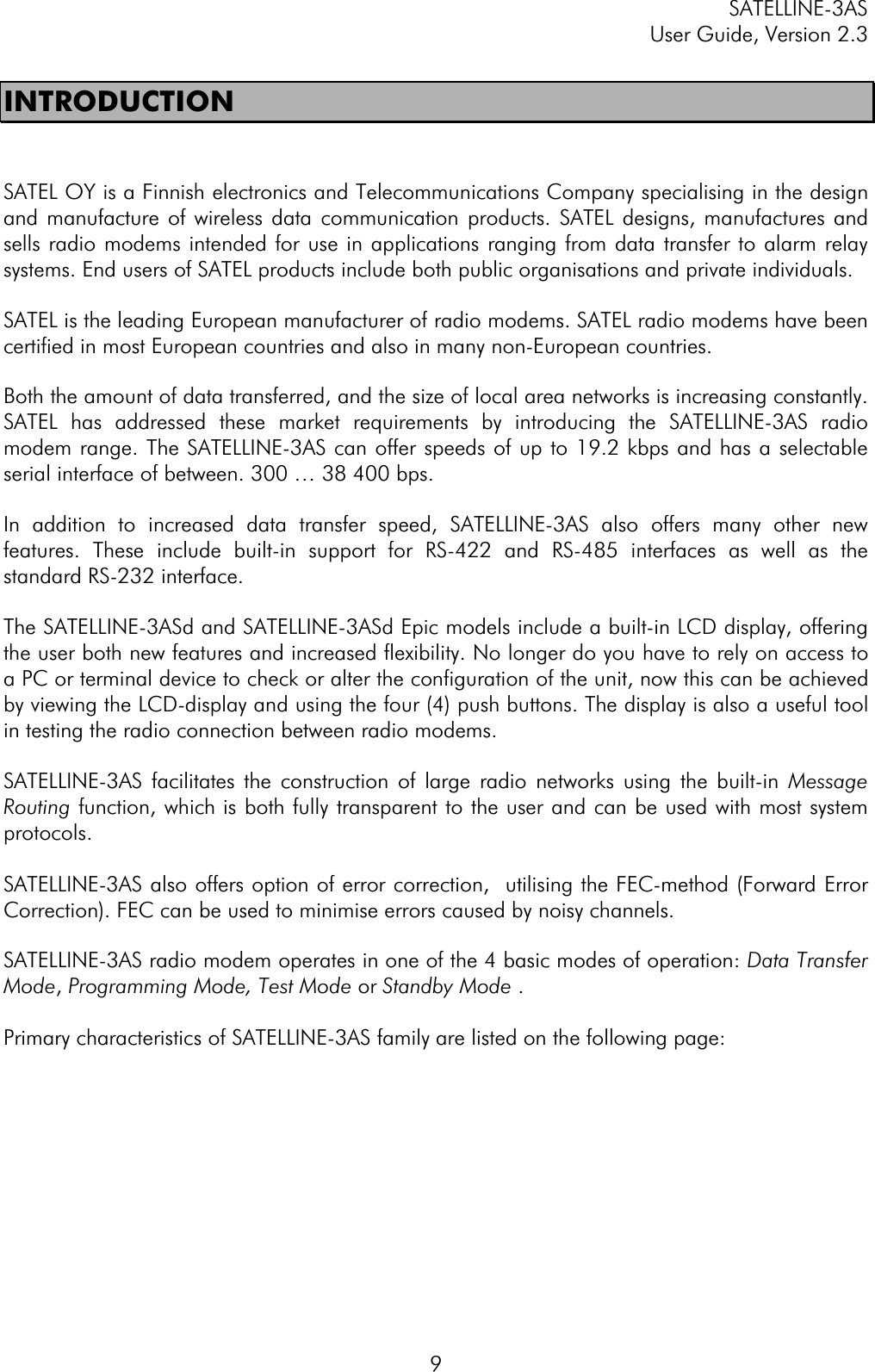
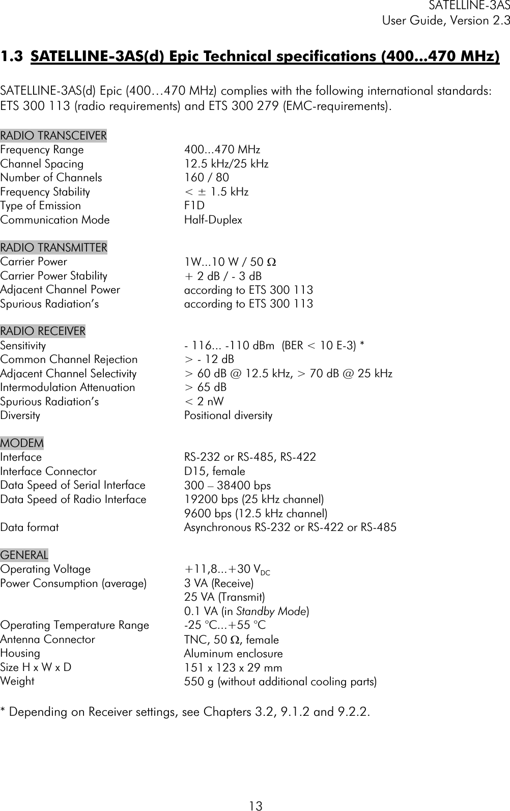
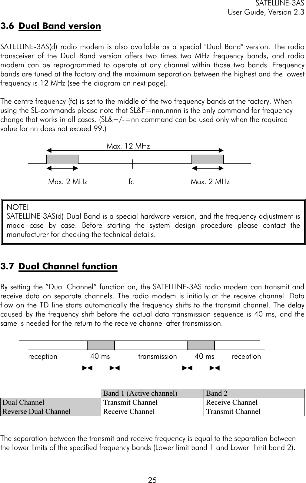
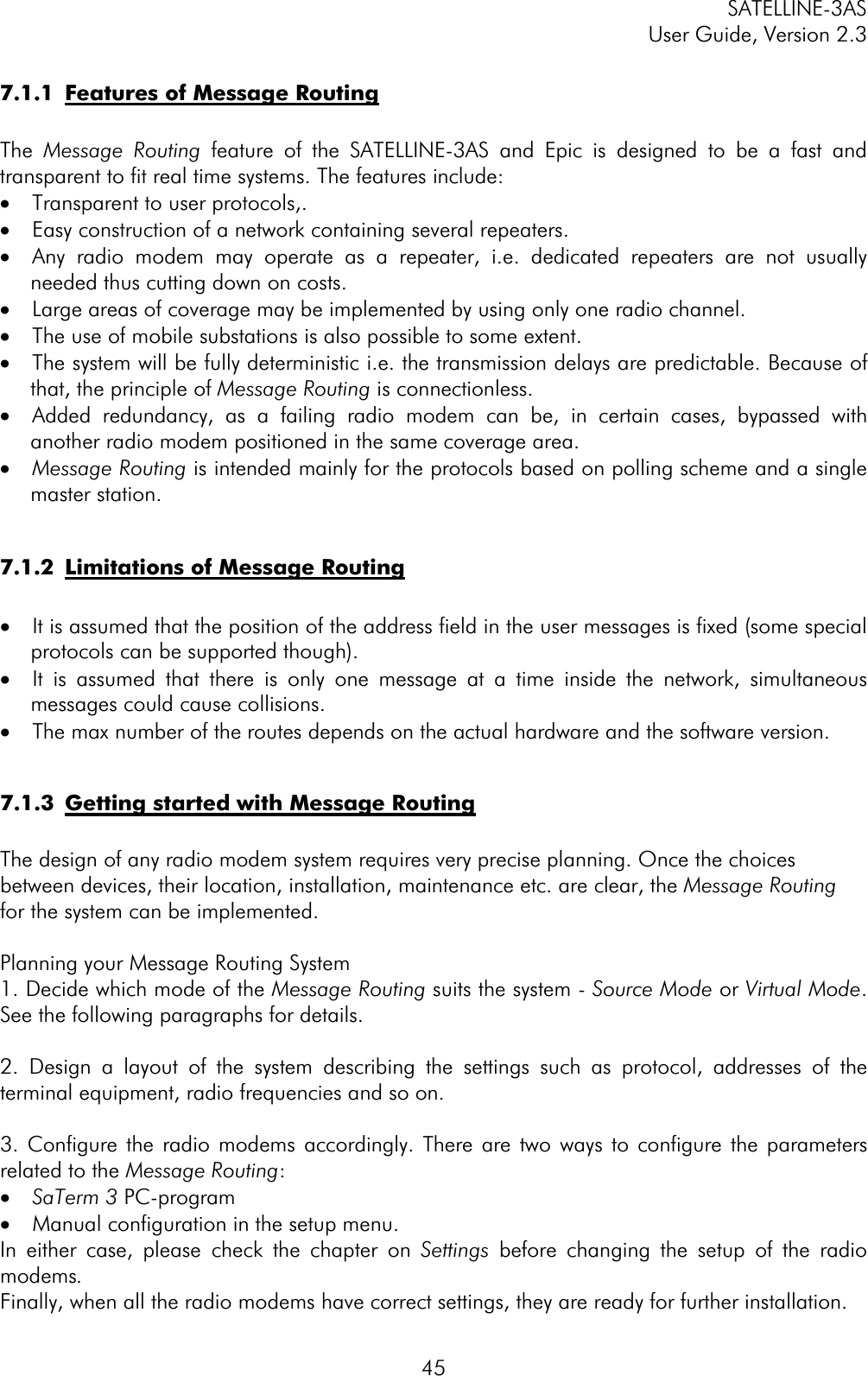
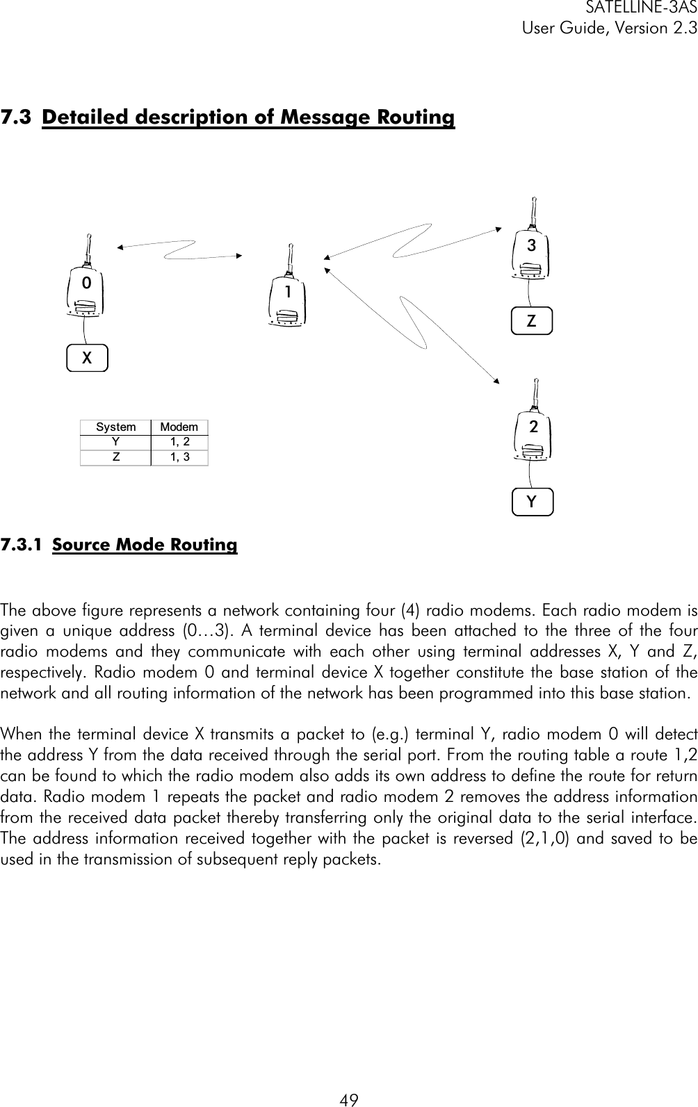
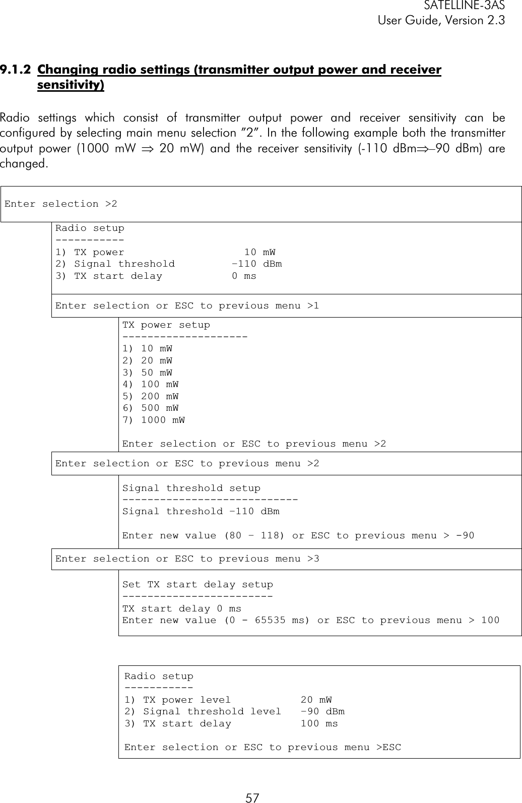
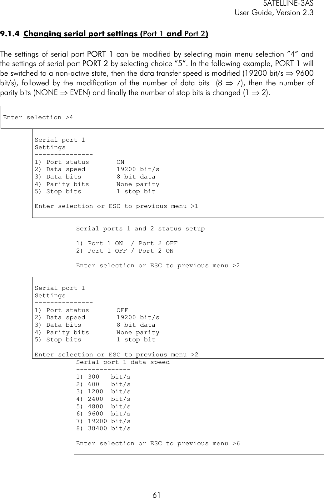
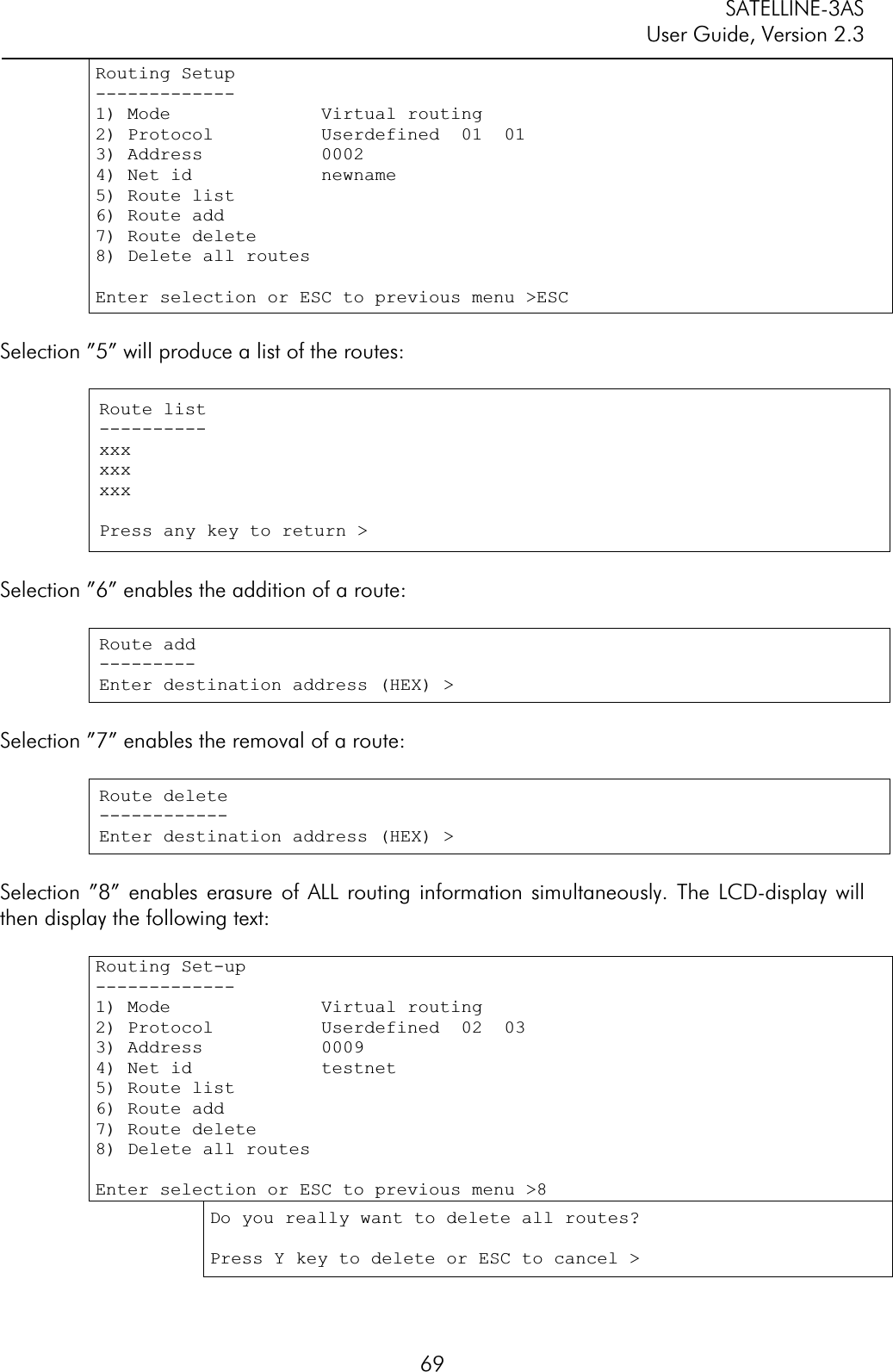
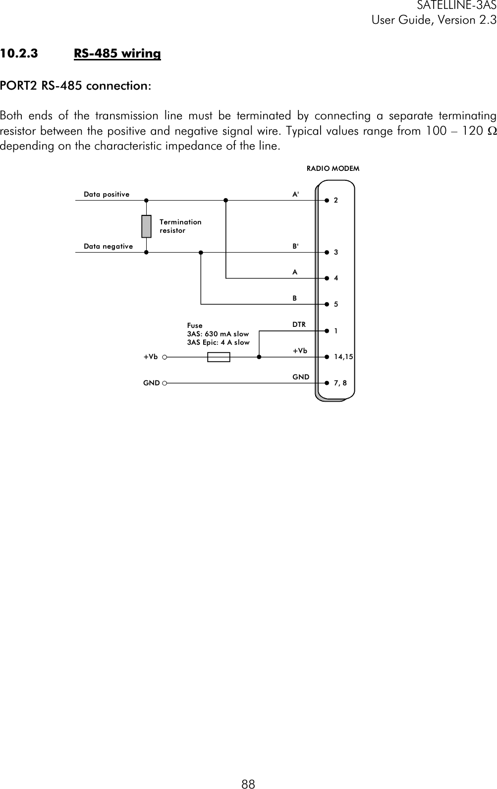
![SATELLINE-3AS User Guide, Version 2.3 82SL#S=xxxx;yyyy Set secondary transmit address (TX2) to value xxxx and receive address (RX2) to value yyyy SL#P? Display primary transmit address (TX1) and receive address (RX1) (response ‘xxxx;yyyy’) SL#S? Display secondary transmit address (TX2) and receive address (RX2) (response ‘xxxx;yyyy’) xxxx = address in hexadecimal format (0000 … FFFF) 9.3.3 Radio parametersCommand Effect and description of command SL@R? Display field strength of the last received message (the value is an average of many measurements made during the same reception). Response ”-xx dBm”, where xx is a decimal value of the field strength and it is between –80 dBm and –118 dBm. Value available 7s after reception. SATELLINE-3AS Epic returns the stronger value of two receivers. SL@P=xxxxx Set the RF output power, where xxxxx is the decimal value of the intended power in milliwatts. If the given value does not correspond to one of the programmed power levels, the output power is set to the nearest possible value. SL@P? Requests the RF output power. Response ”xxxxx mW”, where xxxxx is a decimal value the output power of the transmitter. SL@T=-xxx Set the minimum power level of the signal to be received (="Signal Treshold level), where xxx is a decimal value of the new intended level in dBm. SL@T? Request of the current "Signal Treshold Level". Response is "-xxx dBm. 9.3.4 Other functionsCommand Effect and description of command SL**> Save current settings as permanent settings SL%V? Display software revision information (response ’Vn.nn’) 9.3.5 SATELLINE-2ASx/2ASxE compatible SL-commandsThe commands listed in the table below are included only to ensure compatibility and their use is not recommended in new networks. The commands do not need a CR-character (carriage return) at the end of the command string. Command Effect and description of command SLHxx Set frequency xx channels above center frequency. Frequency = Center frequency + xx*Channel spacing, where xx=[00…99] SLLxx Set frequency xx channels below center frequency. Frequency = Center frequency - xx*Channel spacing, where xx=[00…99]](https://usermanual.wiki/Satel/SATEL-3AS-125.User-manual-of-SATELLINE-3AS/User-Guide-327507-Page-82.png)
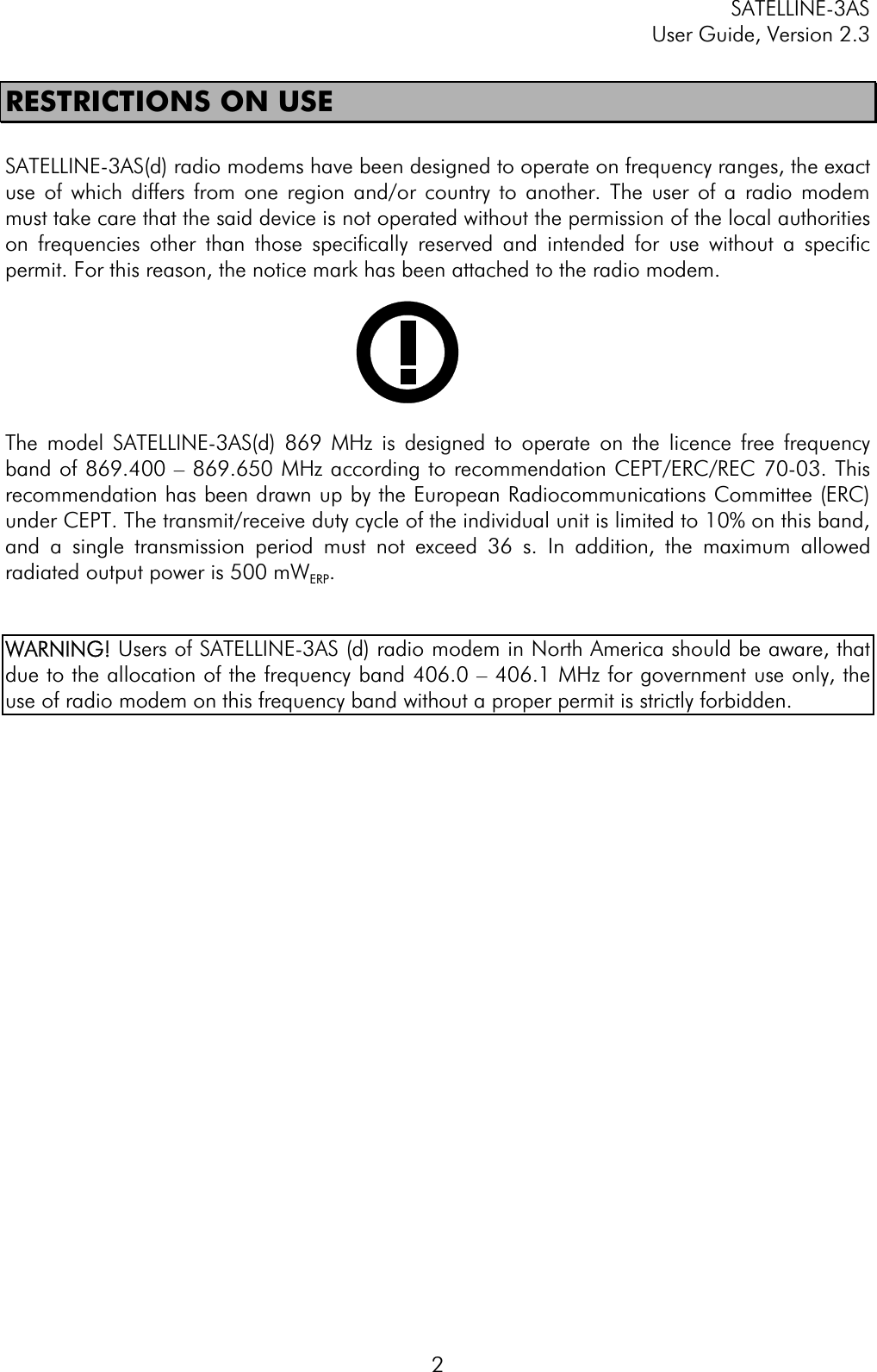
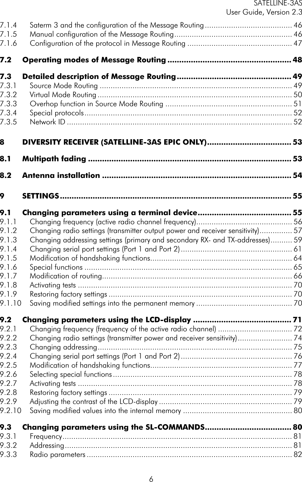
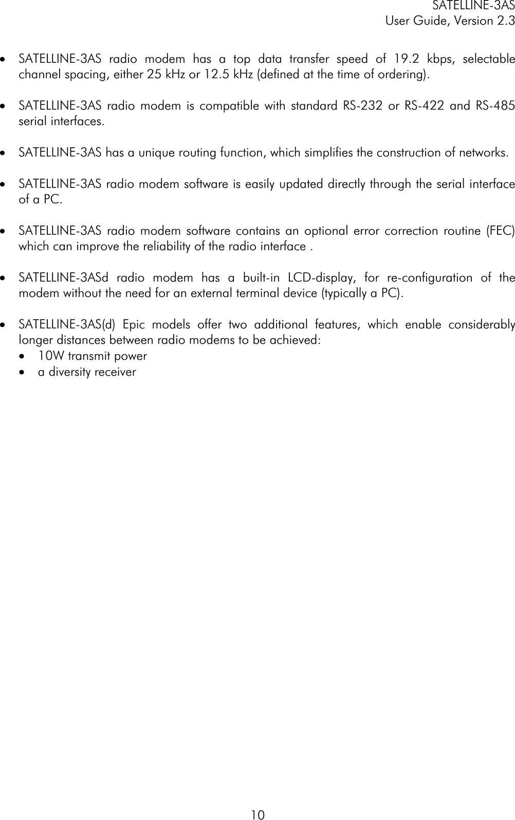
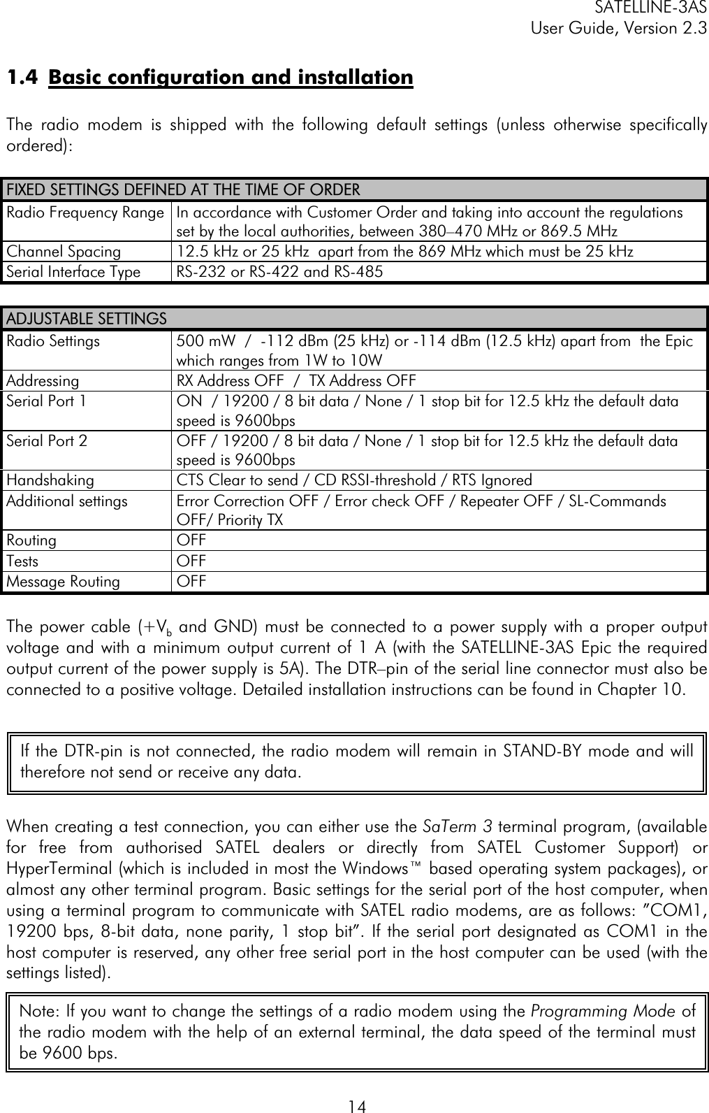
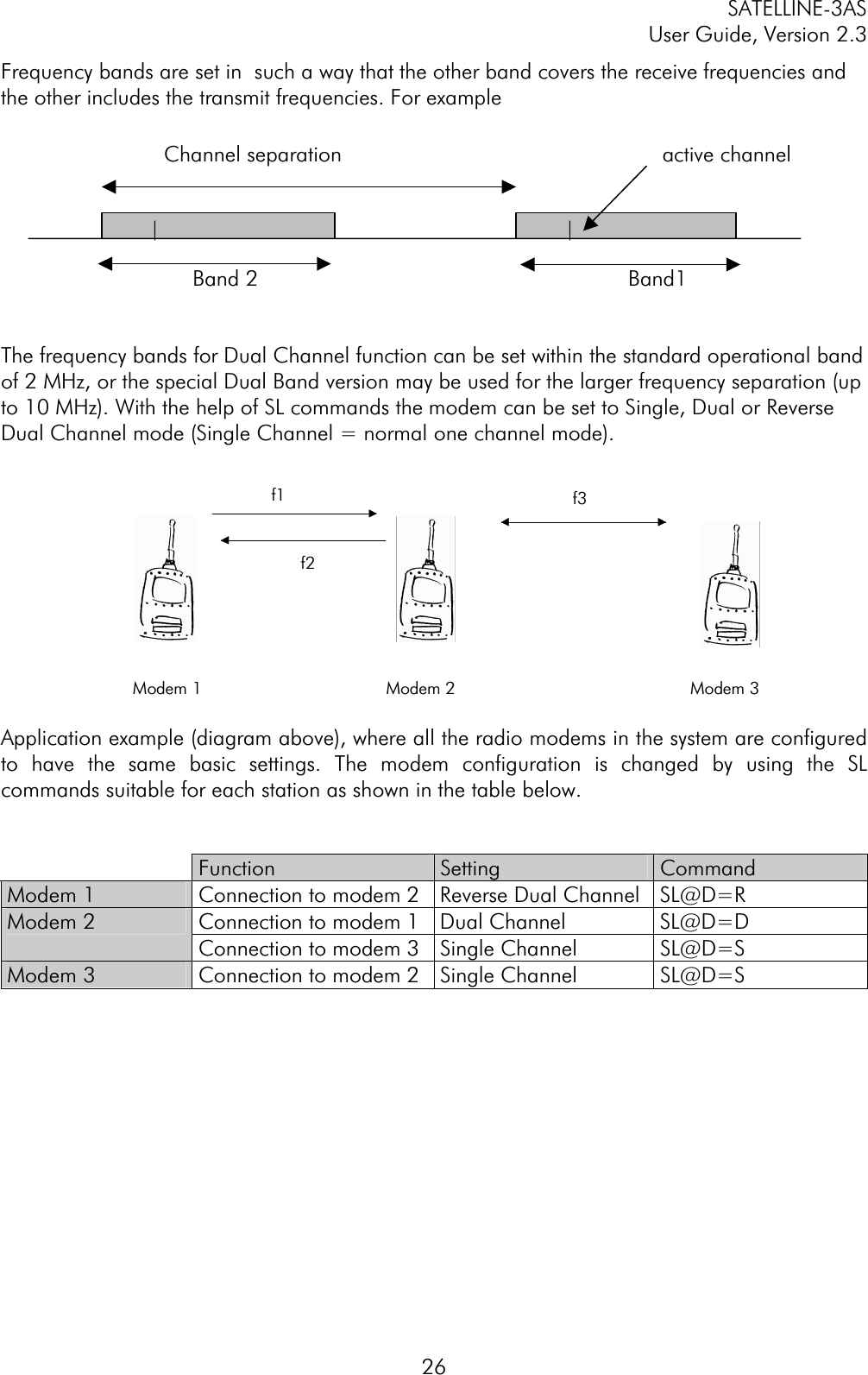
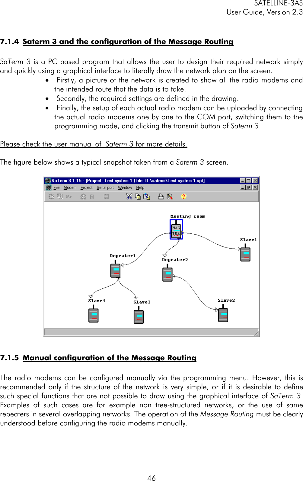
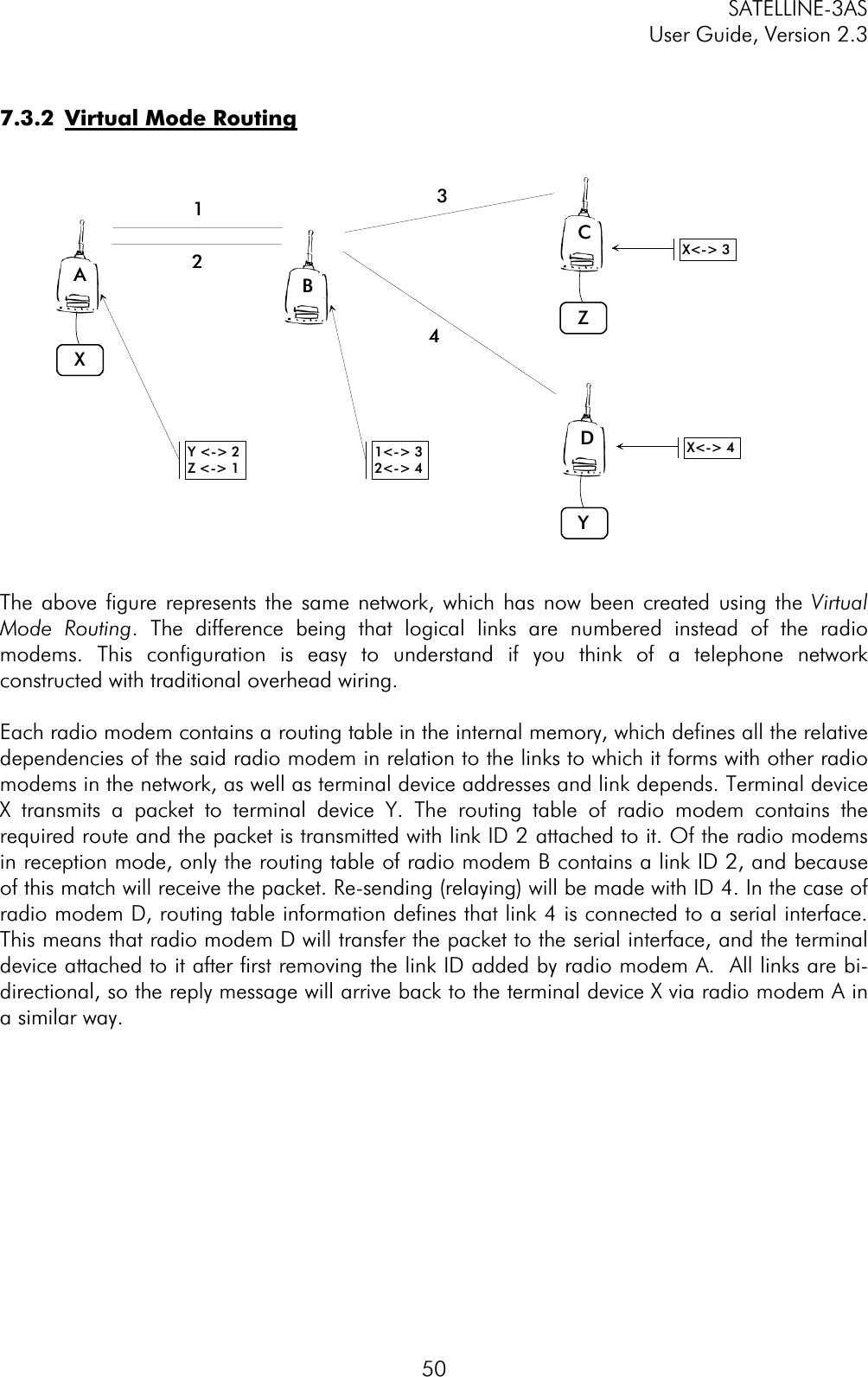
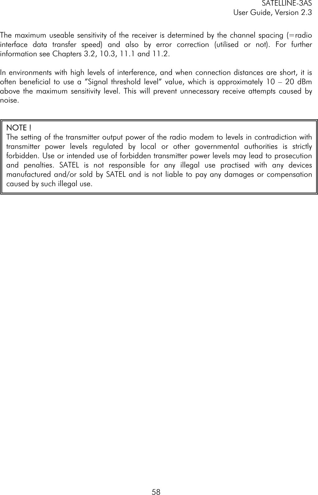
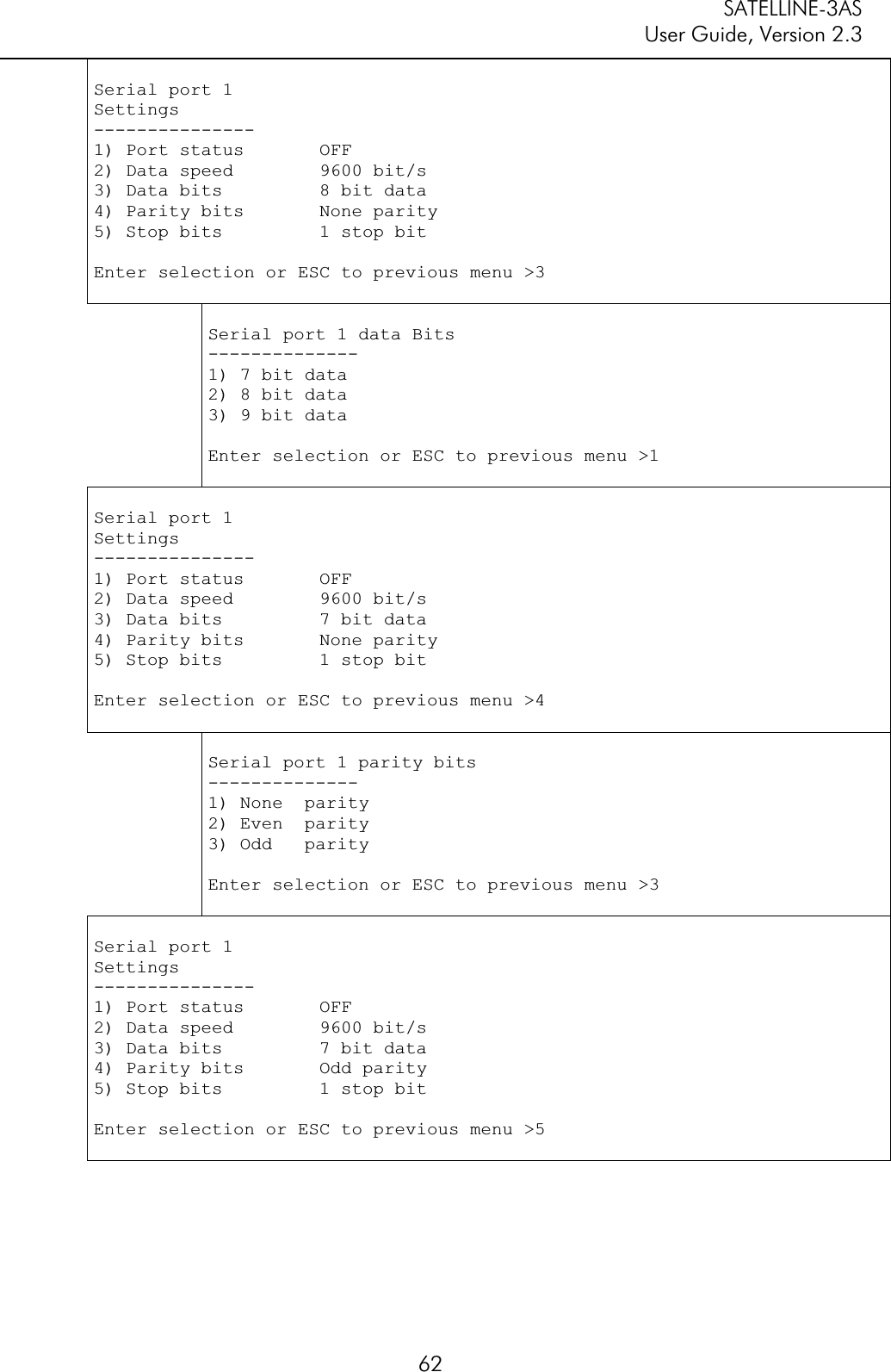
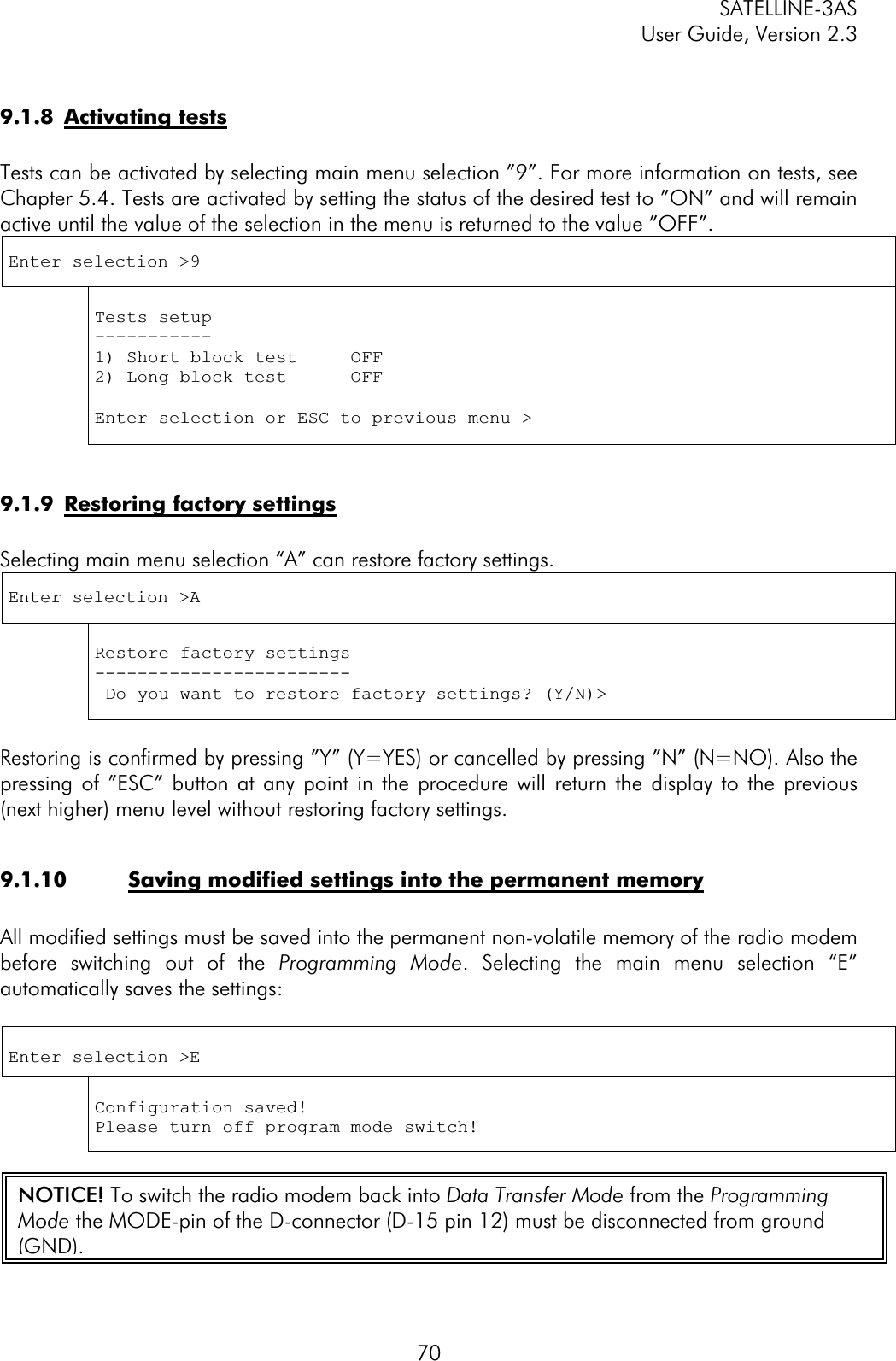
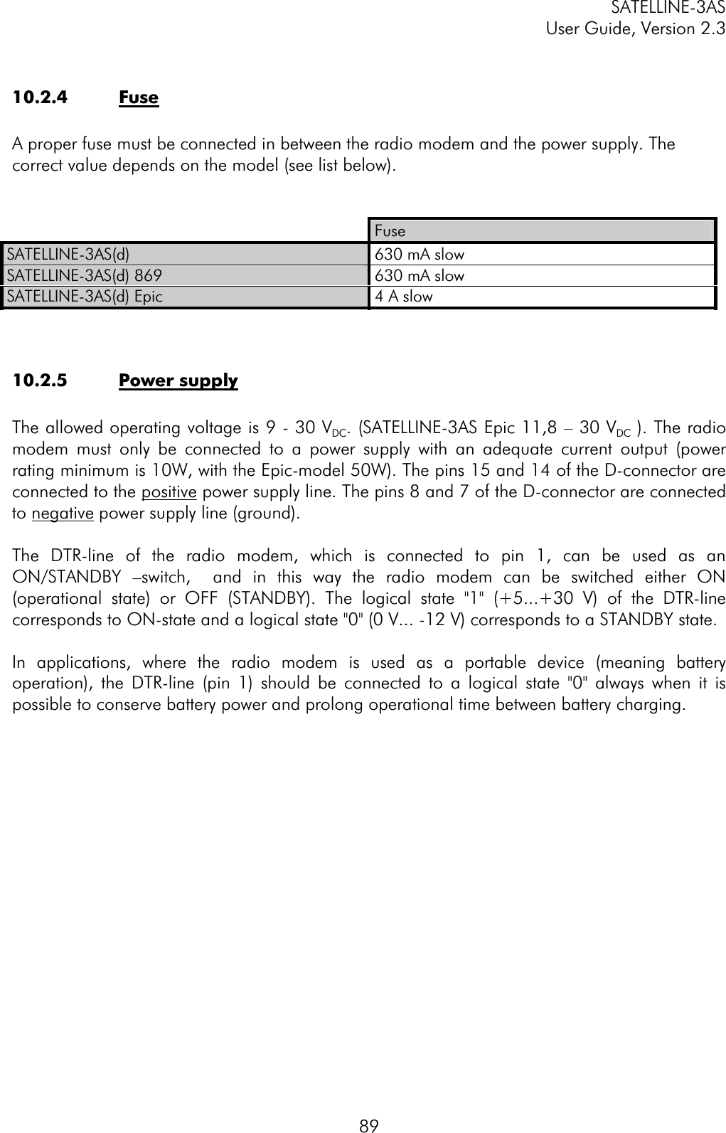
![SATELLINE-3AS User Guide, Version 2.3 83SLAxx Set all addresses (RX1, RX2, TX1, TX2) to value xx, where xx=[00h...FFh] SLTxx Set both transmit addresses (TX1, TX2) to value xx, where xx=[00h...FFh] SLRxx Set both receive addresses (RX1, RX2) to value xx, where xx=[00h...FFh] SLS0S Save current settings as permanent settings](https://usermanual.wiki/Satel/SATEL-3AS-125.User-manual-of-SATELLINE-3AS/User-Guide-327507-Page-83.png)
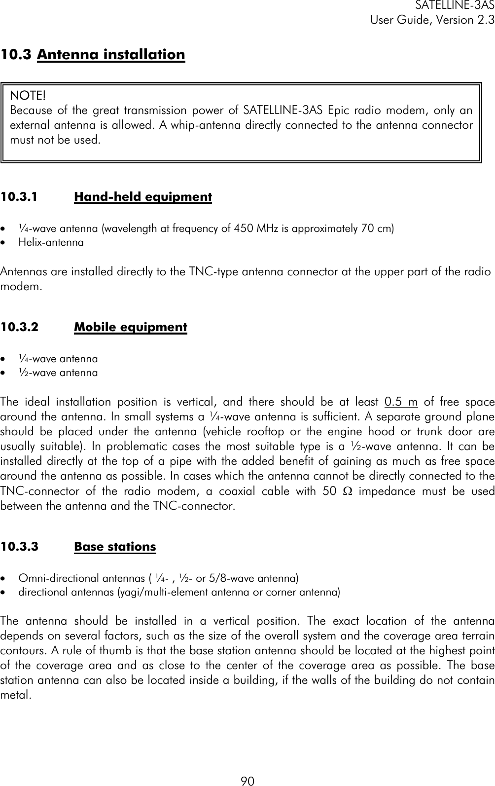
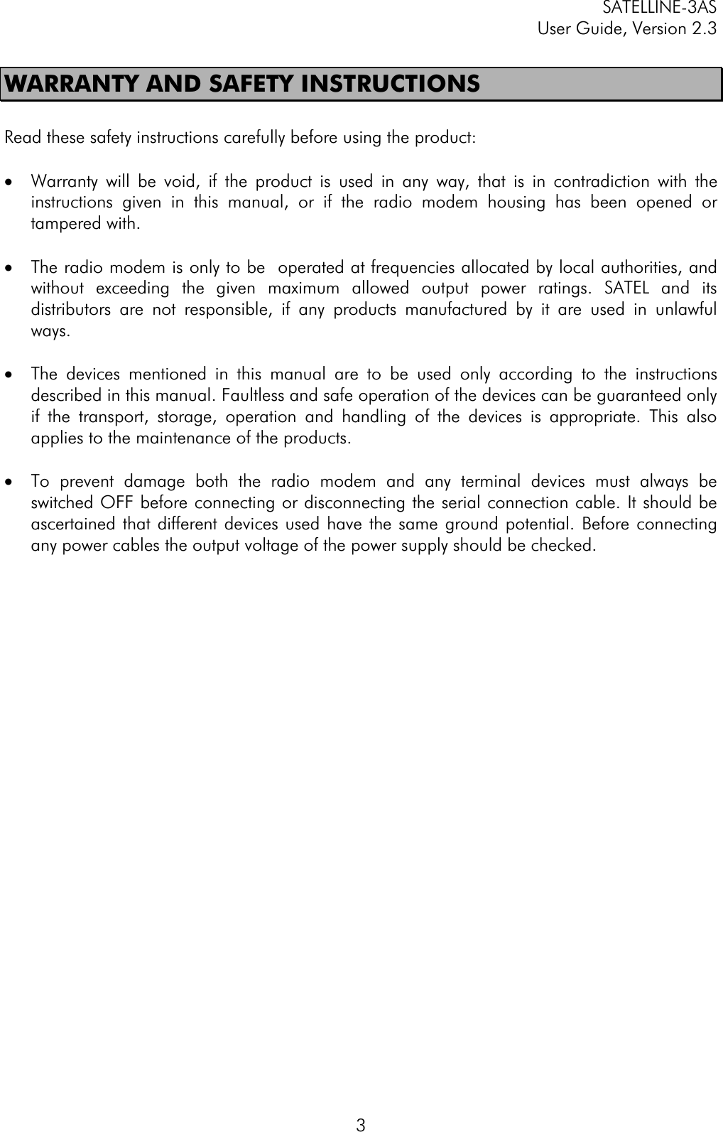
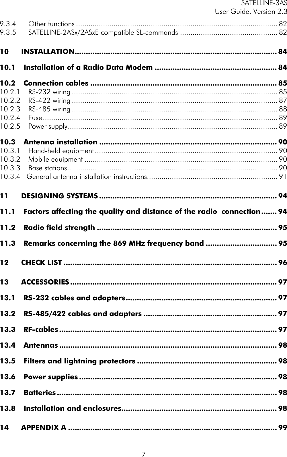
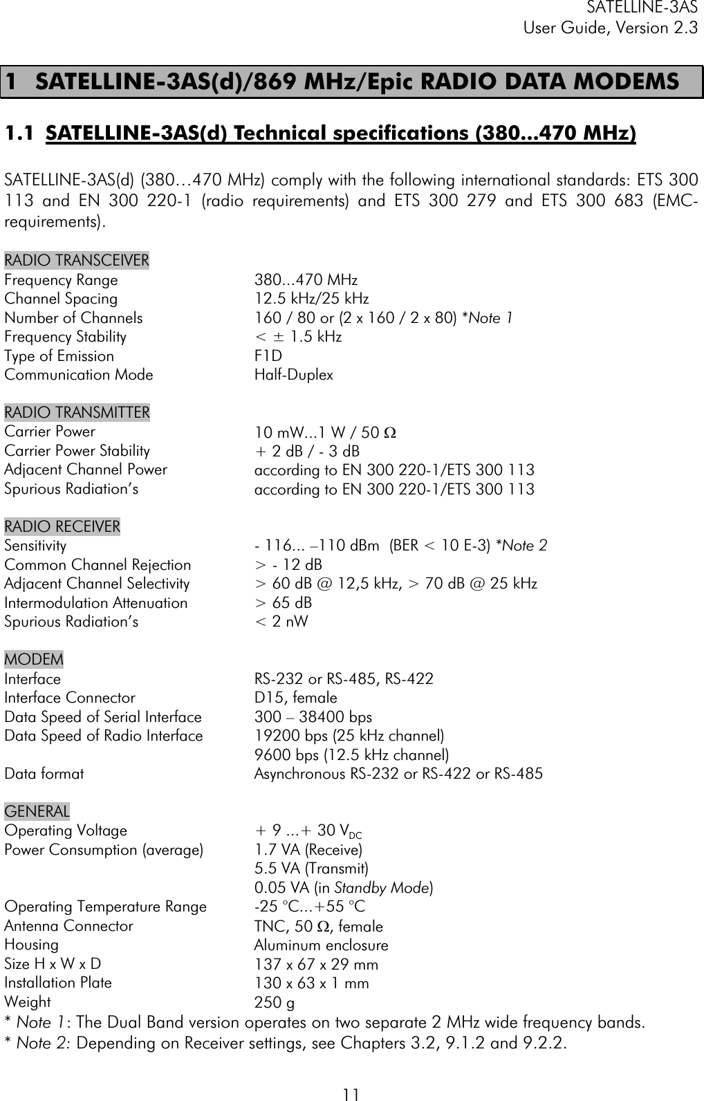
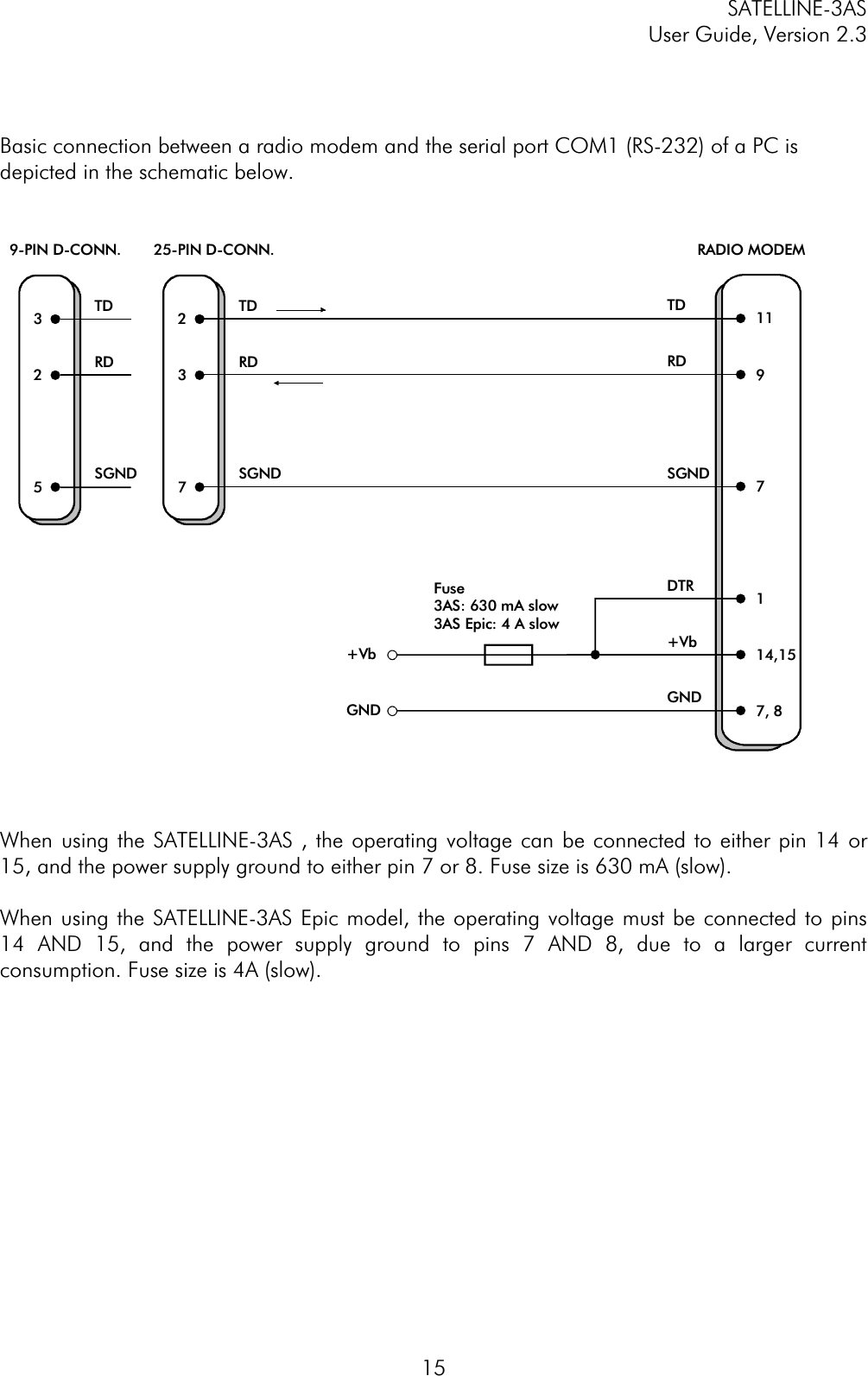
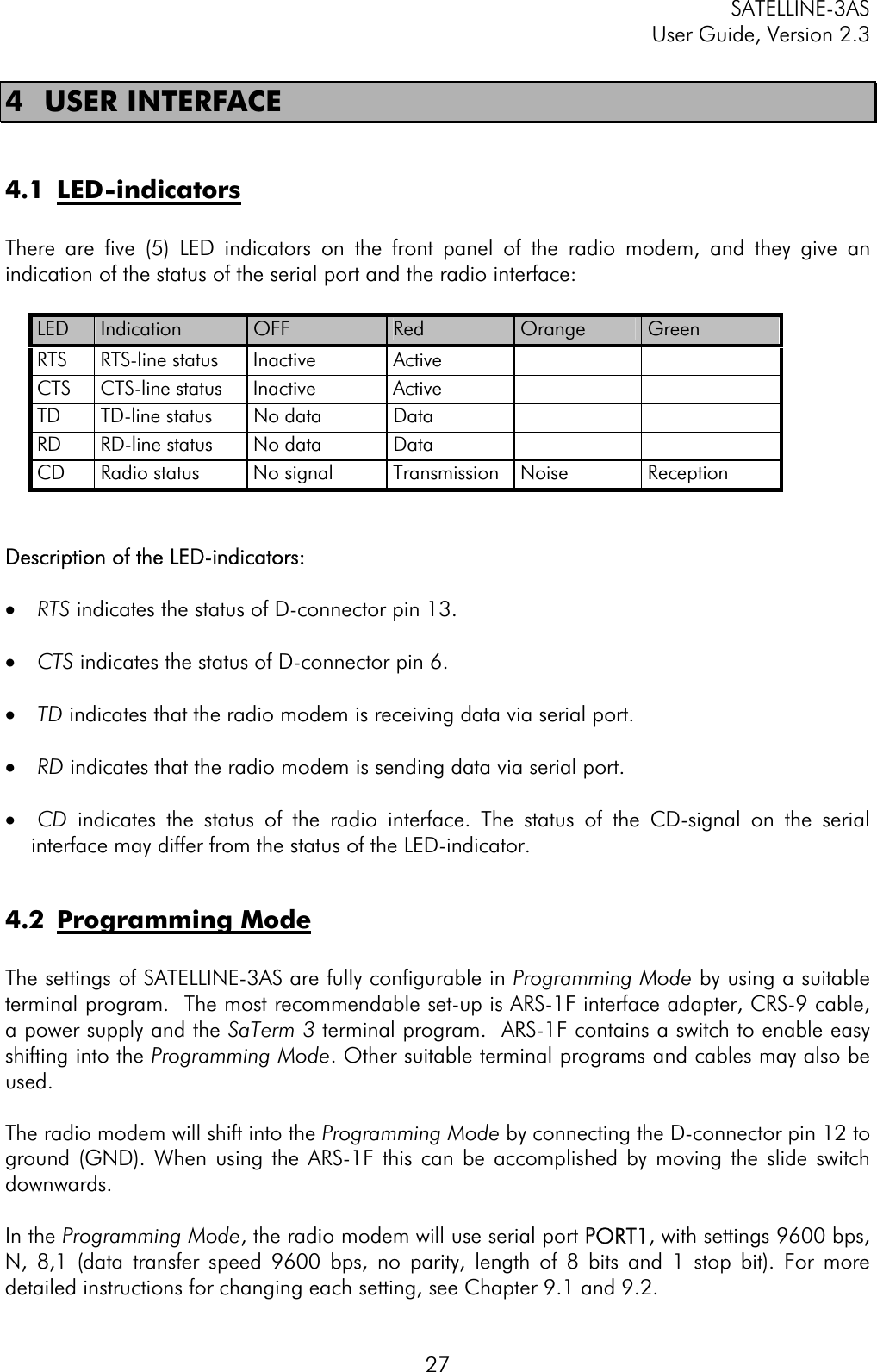
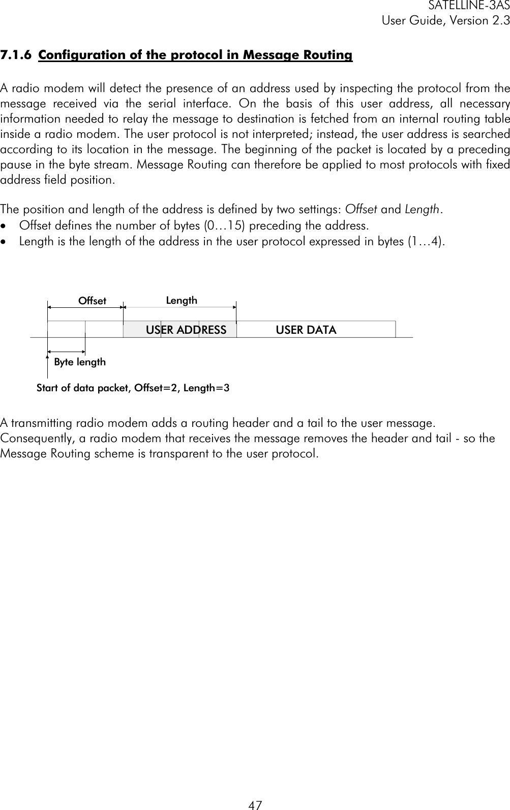
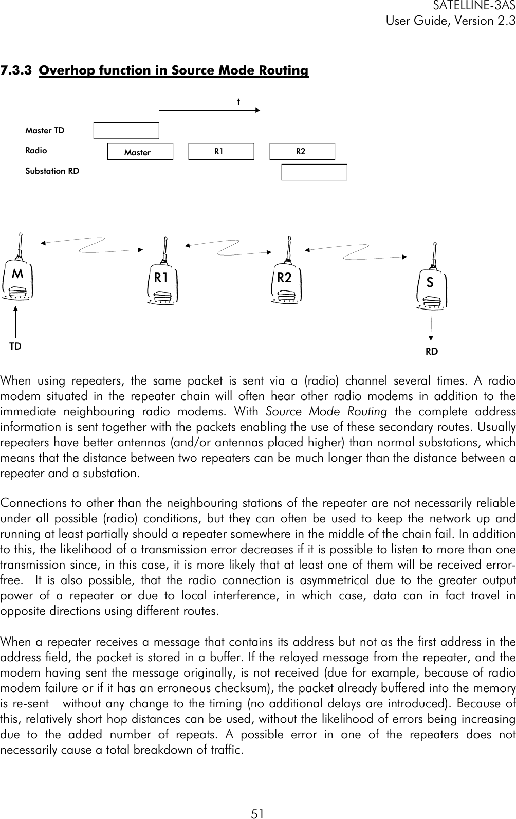
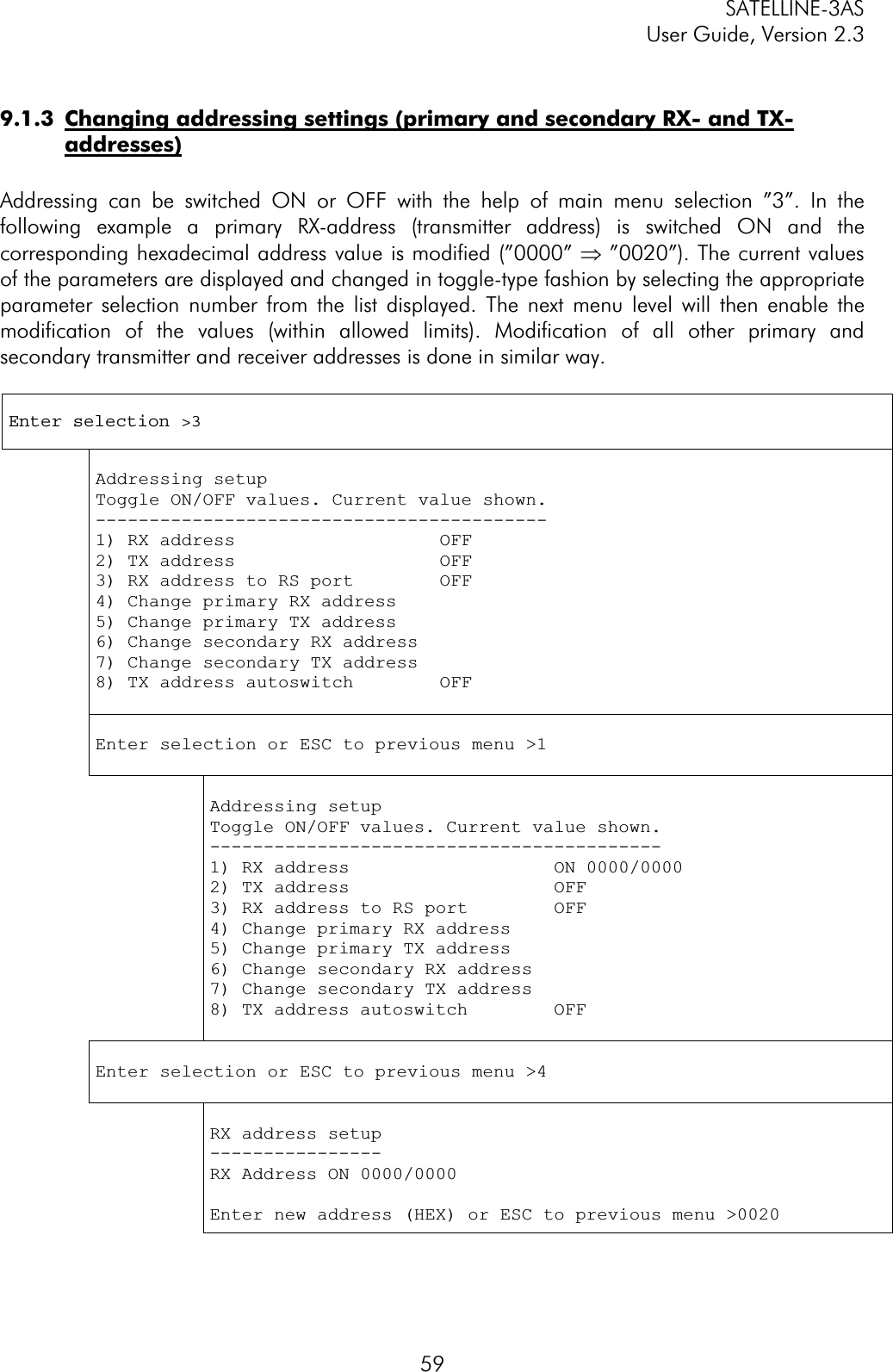
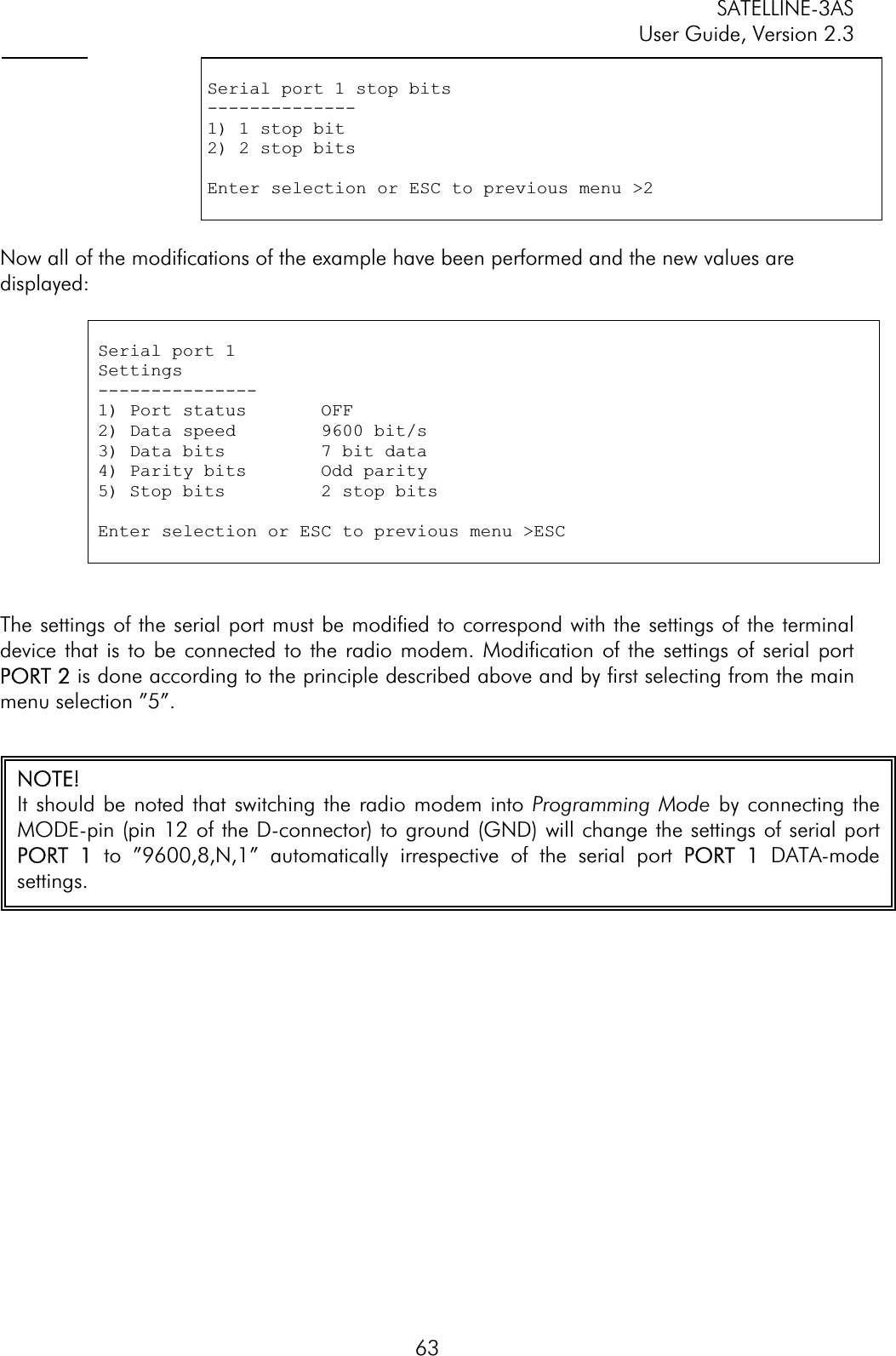
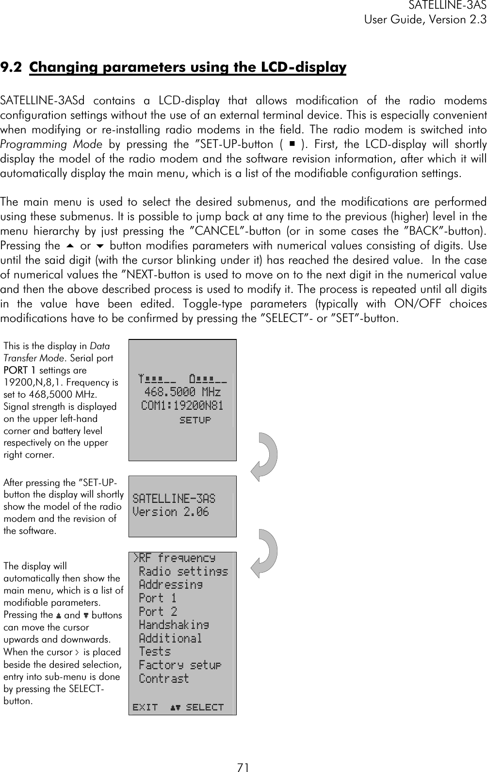
![SATELLINE-3AS User Guide, Version 2.3 9914 APPENDIX A ASCII CHARACTER TABLE D H A DHAD H A DHAD H A DHA0 0 43 2B +86 56 V 129 81 172 AC 215 D71 1 44 2C ,87 57 W 130 82 173 AD 216 D82 2 45 2D -88 58 X 131 83 174 AE 217 D93 3 46 2E .89 59 Y 132 84 175 AF 218 DA4 4 47 2F /90 5A Z 133 85 176 B0 219 DB5 5 48 30 0 91 5B [ 134 86 177 B1 220 DC6 6 49 31 1 92 5C \ 135 87 178 B2 221 DD7 7 50 32 2 93 5D ] 136 88 179 B3 222 DE8 8 51 33 3 94 5E ^ 137 89 180 B4 223 DF9 9 52 34 4 95 5F _ 138 8A 181 B5 224 E010 A 53 35 5 96 60 ` 139 8B 182 B6 225 E111 B 54 36 6 97 61 a 140 8C 183 B7 226 E212 C 55 37 7 98 62 b 141 8D 184 B8 227 E313 D 56 38 8 99 63 c 142 8E 185 B9 228 E414 E 57 39 9 100 64 d 143 8F 186 BA 229 E515 F 58 3A :101 65 e 144 90 187 BB 230 E616 10 59 3B ;102 66 f 145 91 188 BC 231 E717 11 60 3C <103 67 g 146 92 189 BD 232 E818 12 61 3D =104 68 h 147 93 190 BE 233 E919 13 62 3E >105 69 i 148 94 191 BF 234 EA20 14 63 3F ?106 6A j 149 95 192 C0 235 EB21 15 64 40 @ 107 6B k 150 96 193 C1 236 EC22 16 65 41 A 108 6C l 151 97 194 C2 237 ED23 17 66 42 B 109 6D m 152 98 195 C3 238 EE24 18 67 43 C 110 6E n 153 99 196 C4 239 EF25 19 68 44 D 111 6F o 154 9A 197 C5 240 F026 1A 69 45 E 112 70 p 155 9B 198 C6 241 F127 1B 70 46 F 113 71 q 156 9C 199 C7 242 F228 1C 71 47 G 114 72 r 157 9D 200 C8 243 F329 1D 72 48 H 115 73 s 158 9E 201 C9 244 F430 1E 73 49 I 116 74 t 159 9F 202 CA 245 F531 1F 74 4A J117 75 u 160 A0 203 CB 246 F632 20 75 4B K118 76 v 161 A1 204 CC 247 F733 21 ! 76 4C L119 77 w 162 A2 205 CD 248 F834 22 " 77 4D M120 78 x 163 A3 206 CE 249 F935 23 # 78 4E N121 79 y 164 A4 207 CF 250 FA36 24 $ 79 4F O122 7A z 165 A5 208 D0 251 FB37 25 % 80 50 P 123 7B { 166 A6 209 D1 252 FC38 26 & 81 51 Q 124 7C | 167 A7 210 D2 253 FD39 27 ' 82 52 R 125 7D } 168 A8 211 D3 254 FE40 28 ( 83 53 S 126 7E ~ 169 A9 212 D4 255 FF41 29 ) 84 54 T 127 7F 170 AA 213 D5 42 2A * 85 55 U 128 80 171 AB 214 D6](https://usermanual.wiki/Satel/SATEL-3AS-125.User-manual-of-SATELLINE-3AS/User-Guide-327507-Page-99.png)