Satel SATEL-3AS-VHF SATELLINE-3AS VHF User Manual Satelline 3AS UserGuide V2 6a
Satel Oy SATELLINE-3AS VHF Satelline 3AS UserGuide V2 6a
UserManual.wiki
>
Satel
>
SATEL 3AS VHF User Manual
User Manual of SATELLINE 3AS VHF
Navigation menu
Upload a User Manual
Namespaces
Wiki Guide
HTML
PDF
Info
Views
User Manual
Discussion / Help
Navigation
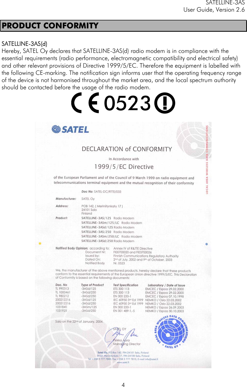
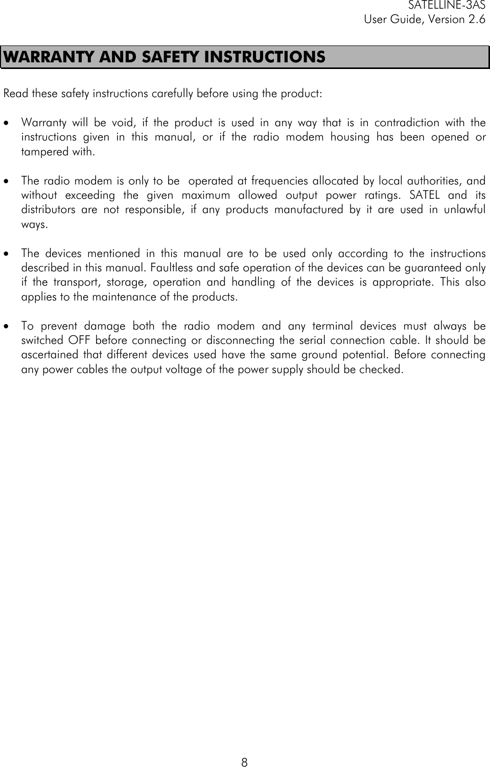
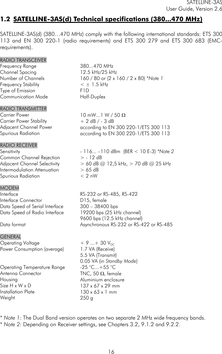
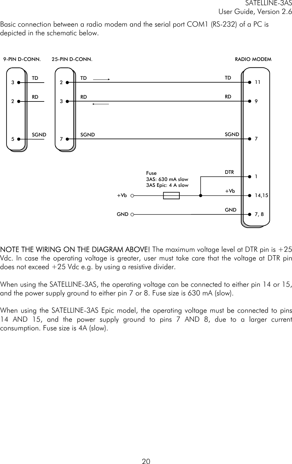
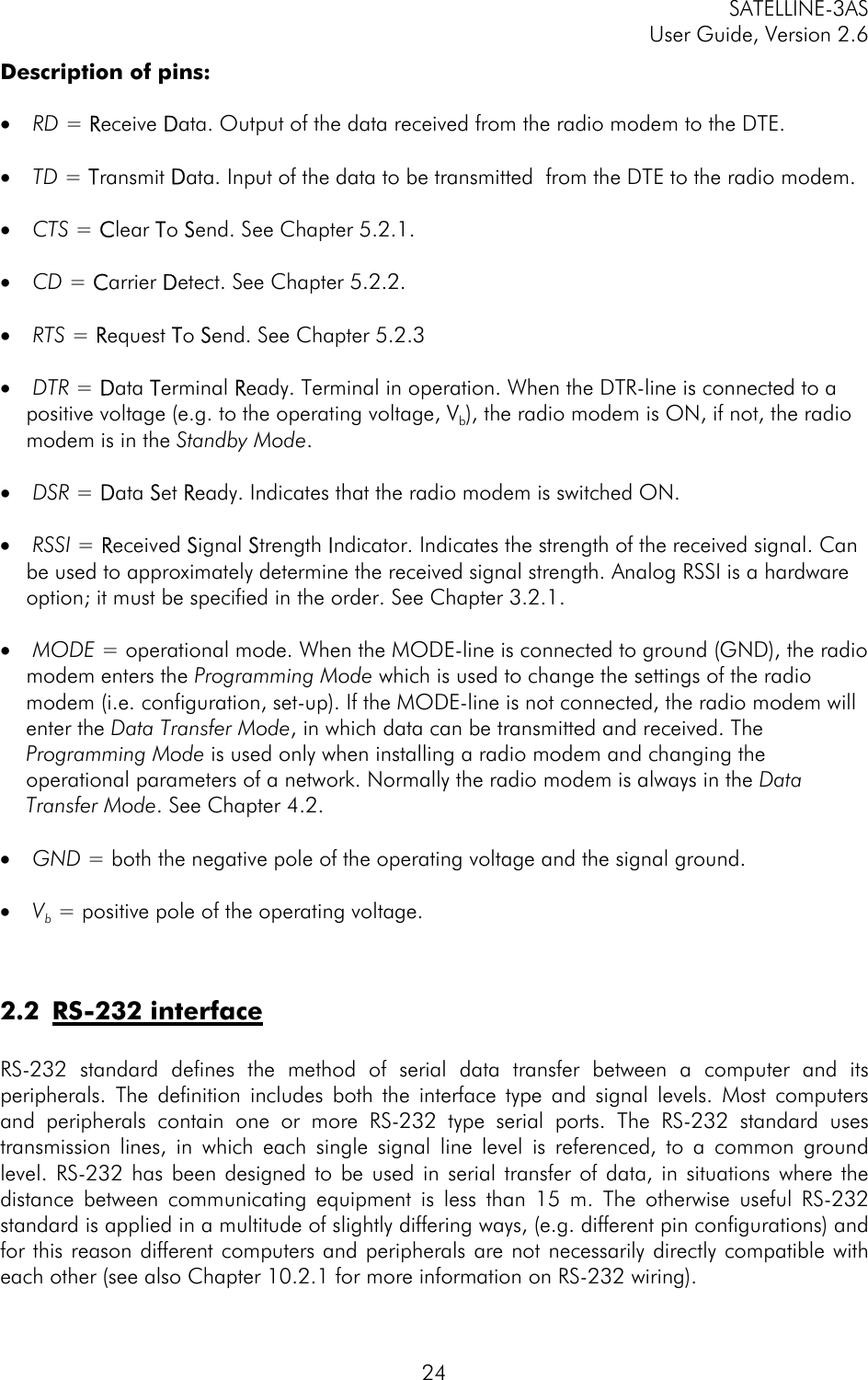
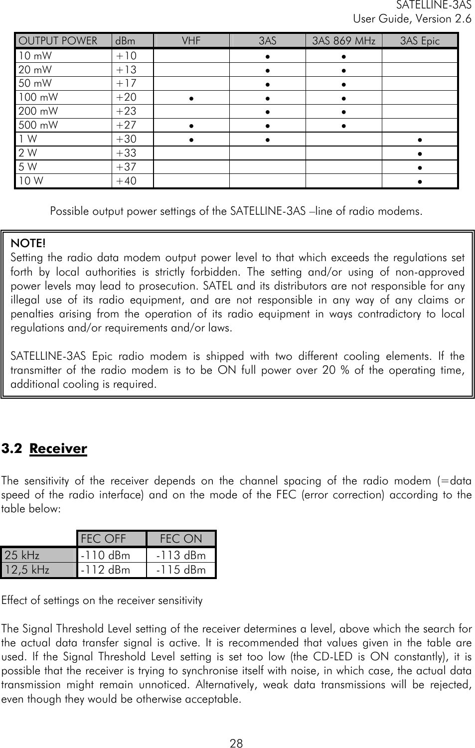
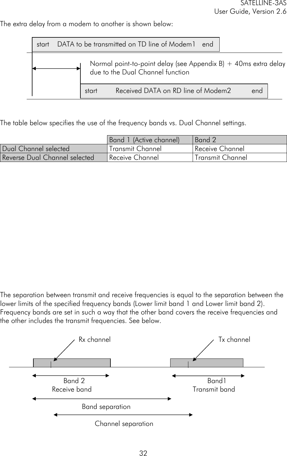
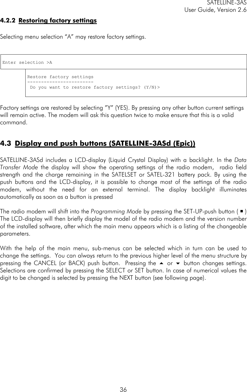
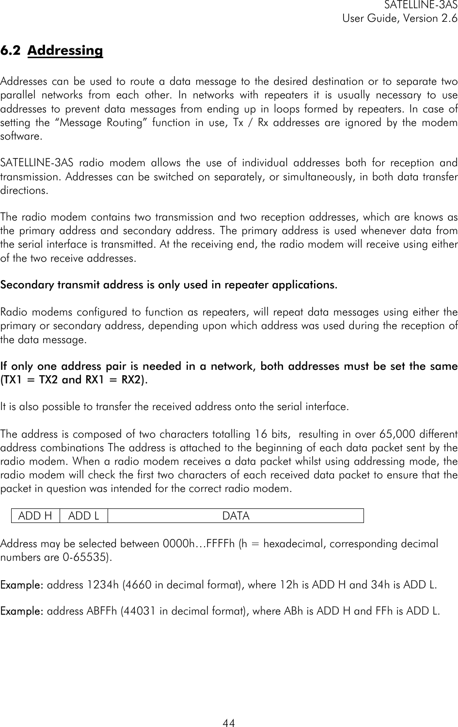
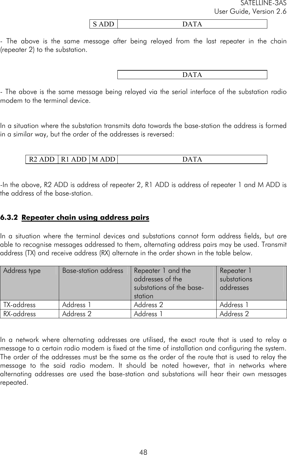
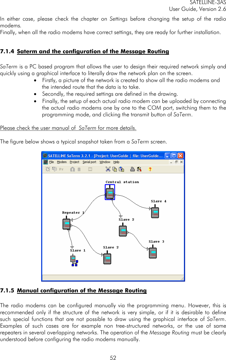
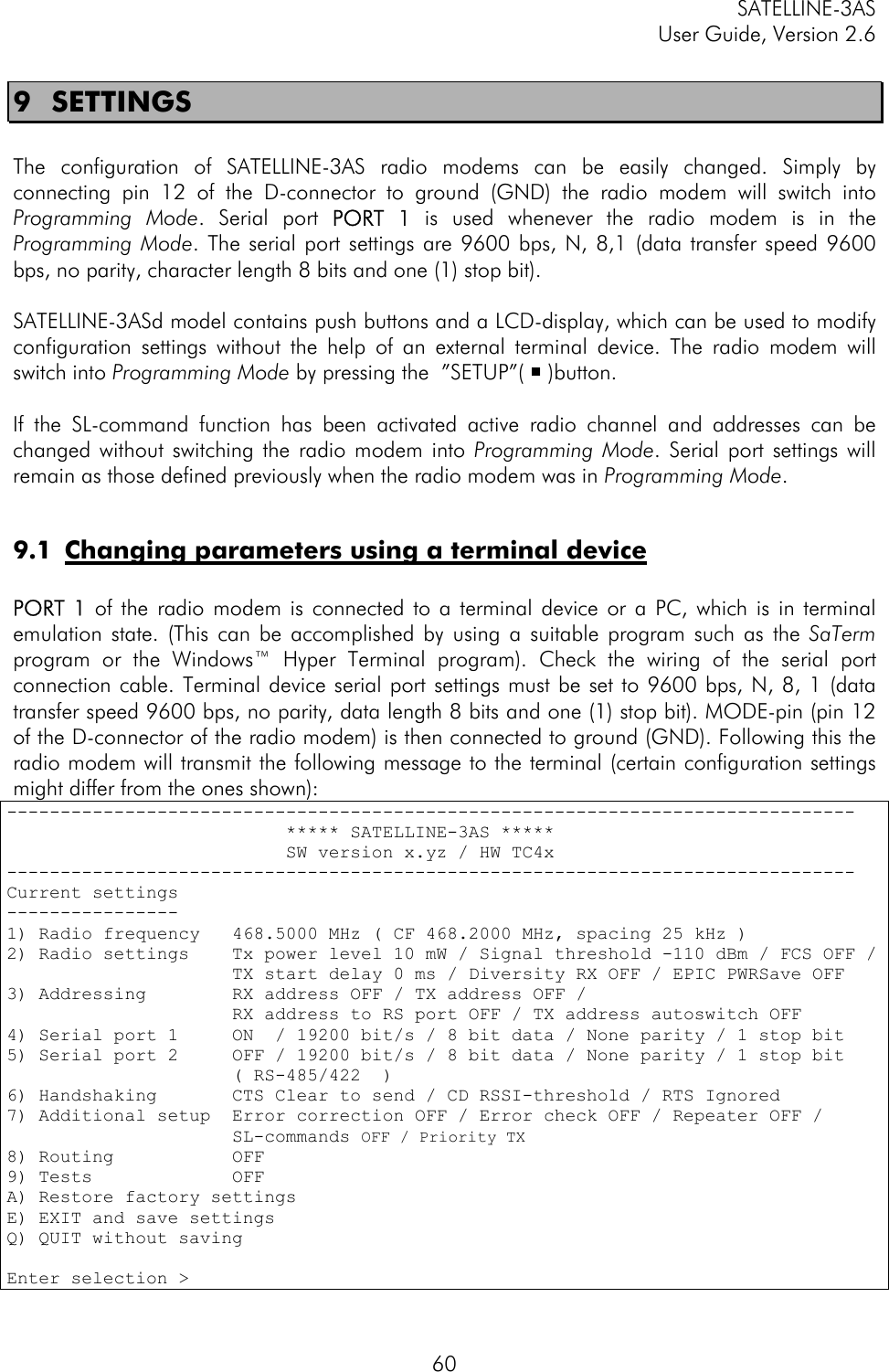
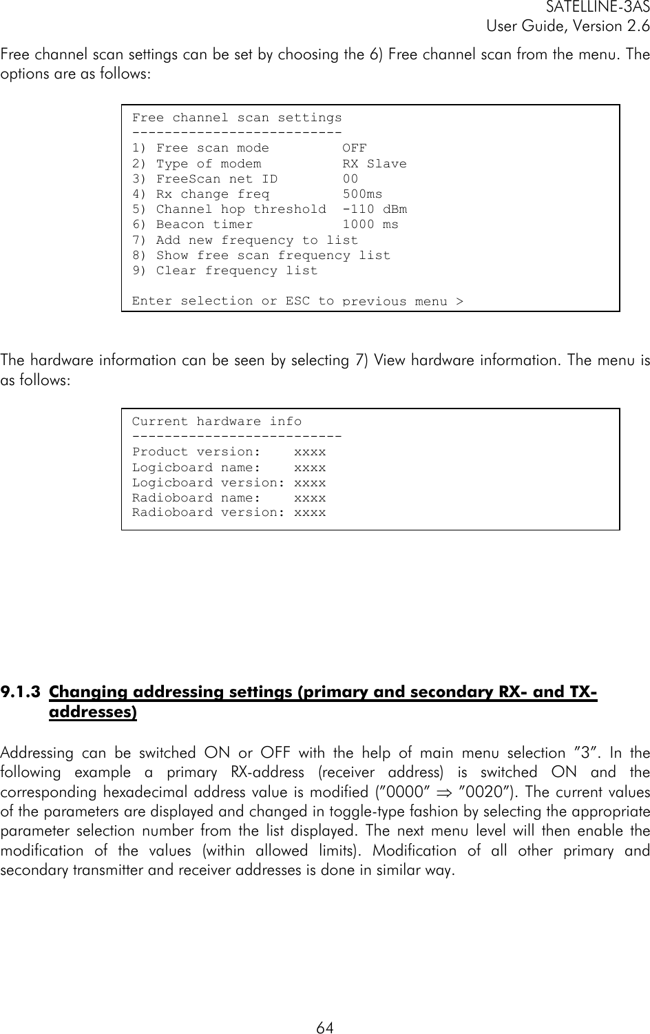
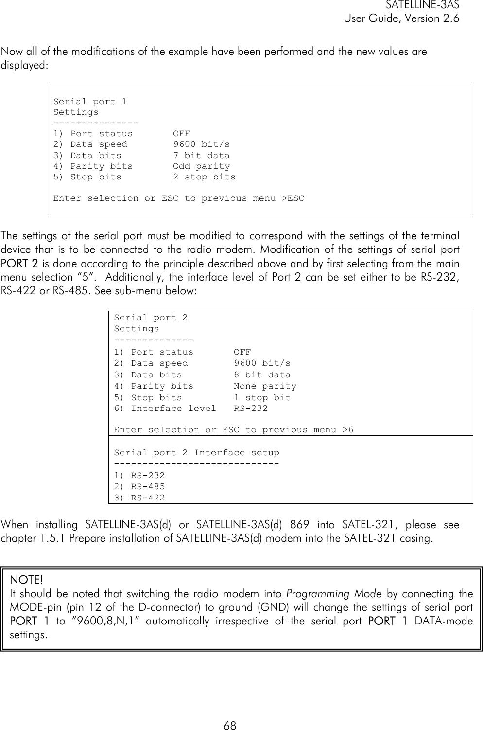
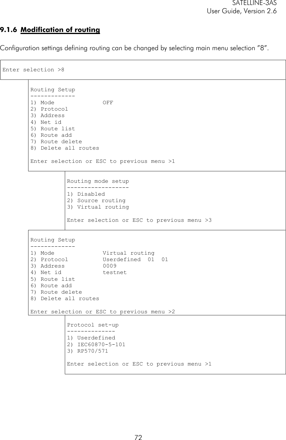
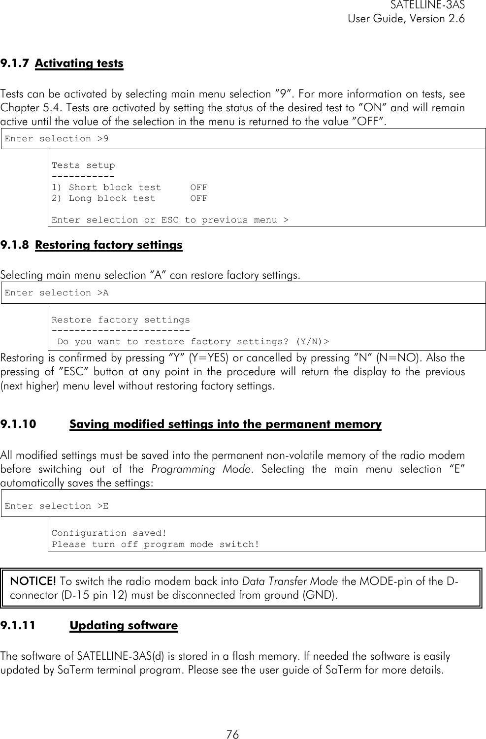
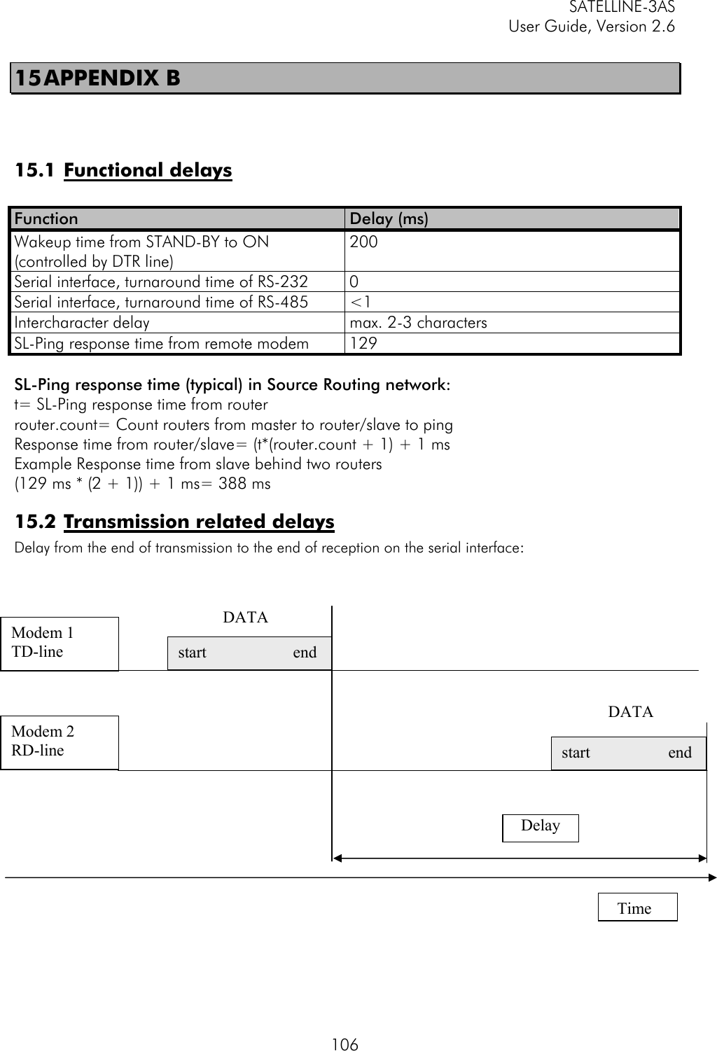
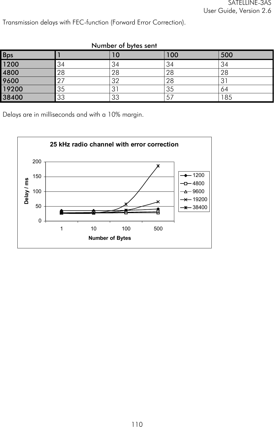
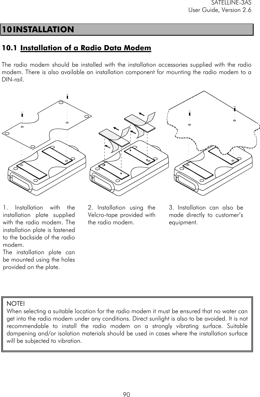
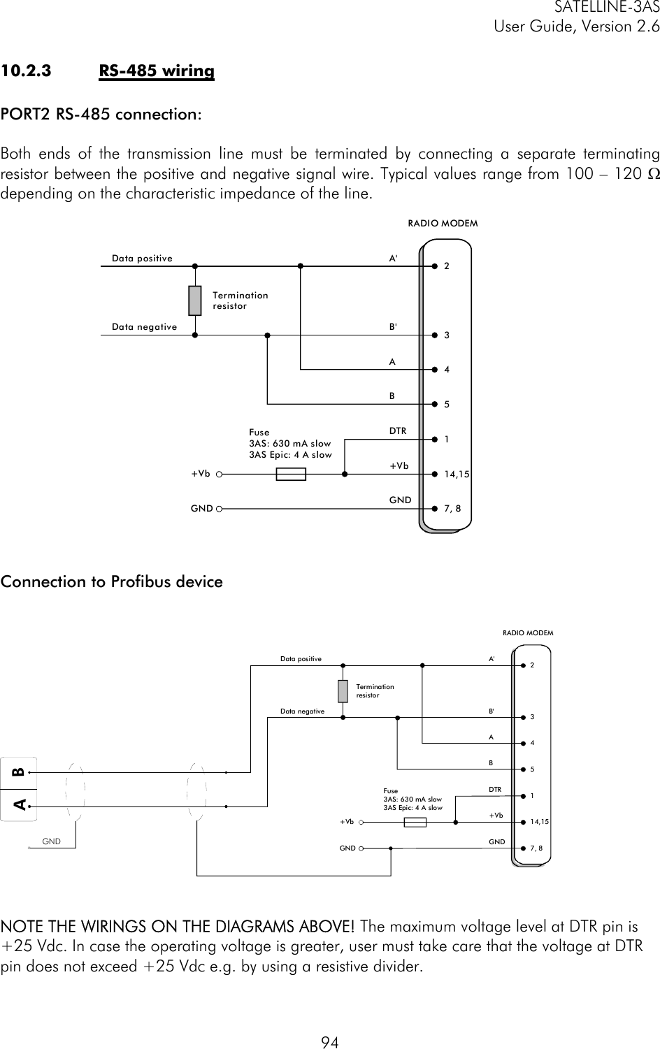
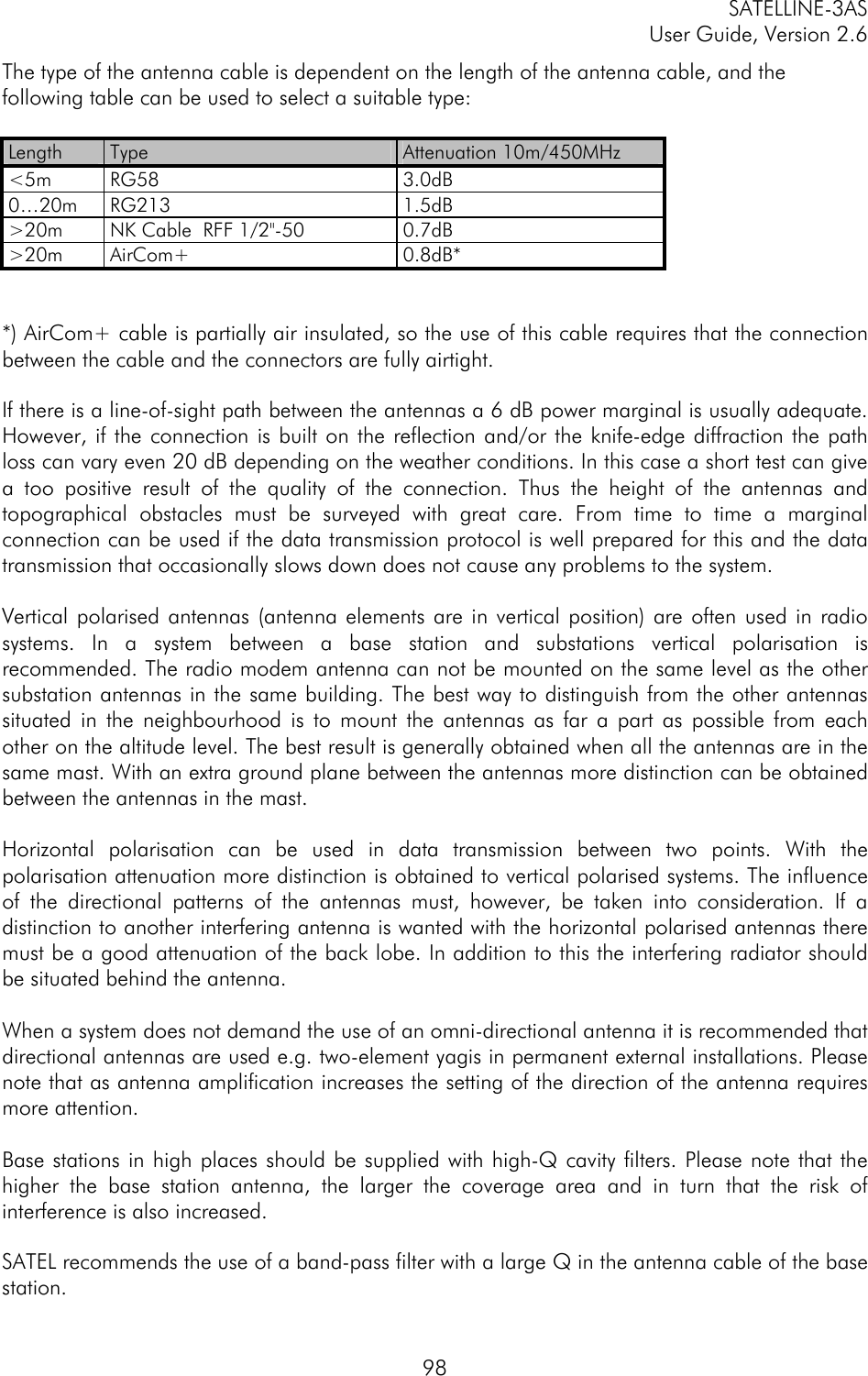
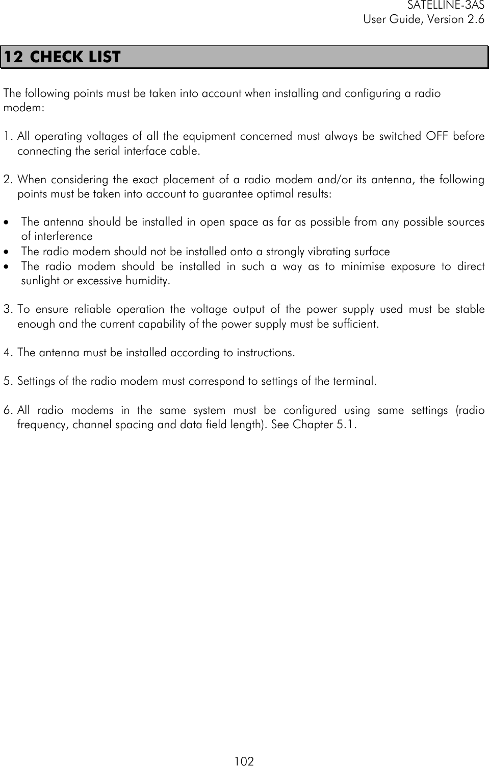
![SATELLINE-3AS User Guide, Version 2.6 879.3.1 Frequency Command Effect and description of command SL&F=nnn.nnnnn Set frequency to nnn.nnnnn MHz SL&F? Display current frequency (response 'nnn.nnnnn MHz') SL&C? Display center frequency (response 'nnn.nnnnn MHz') SL&+=nn Set frequency nn channels above center frequency Frequency = Center frequency + nn * Channel spacing, where nn=[0...Number of channels/2] SL&-=nn Set frequency nn channels below center frequency Frequency = Center frequency – nn * Channel spacing, where nn=[0…Number of channels/2] SL&N? Display current frequency deviation from center frequency as channels (Frequency – Center frequency)/Channel spacing (response ‘+nn’ or ‘-nn’) SL&D=x Sets the operational mode of the radio. The different values of x are: ”S” = Single Channel ”D” = Dual Channel ”R” = Reverse Dual Channel Note! Use this command only, if the setup of the frequency bands matches the Dual Channel operation. SL&D? Request the operational mode of the radio. The response is one of the following: ”S” = Single Channel ”D” = Dual Channel ”R” = Reverse Dual Channel Note! Use this command only, if the setup of the frequency bands matches the Dual Channel operation. 9.3.2 Addressing xxxx = address in hexadecimal format (0000 … FFFF) Command Effect and description of command SL#I=xxxx Set all addresses (RX1, RX2, TX1, TX2) to value xxxx SL#I? Display both primary addresses (TX1, RX1) (response ’xxxx;yyyy’) SL#T=xxxx Set both transmit addresses (TX1, TX2) to value xxxx SL#T? Display primary transmit address (TX1) (response ‘xxxx’) SL#R=xxxx Set both receive addresses (RX1, RX2) to value xxxx SL#R? Display primary receive address (RX1) (response ‘xxxx’) SL#P=xxxx;yyyy Set primary transmit address (TX1) to value xxxx and receive address (RX1) to value yyyy SL#S=xxxx;yyyy Set secondary transmit address (TX2) to value xxxx and receive address (RX2) to value yyyy SL#P? Display primary transmit address (TX1) and receive address (RX1) (response ‘xxxx;yyyy’) SL#S? Display secondary transmit address (TX2) and receive address (RX2) (response ‘xxxx;yyyy’)](https://usermanual.wiki/Satel/SATEL-3AS-VHF/User-Guide-587228-Page-87.png)
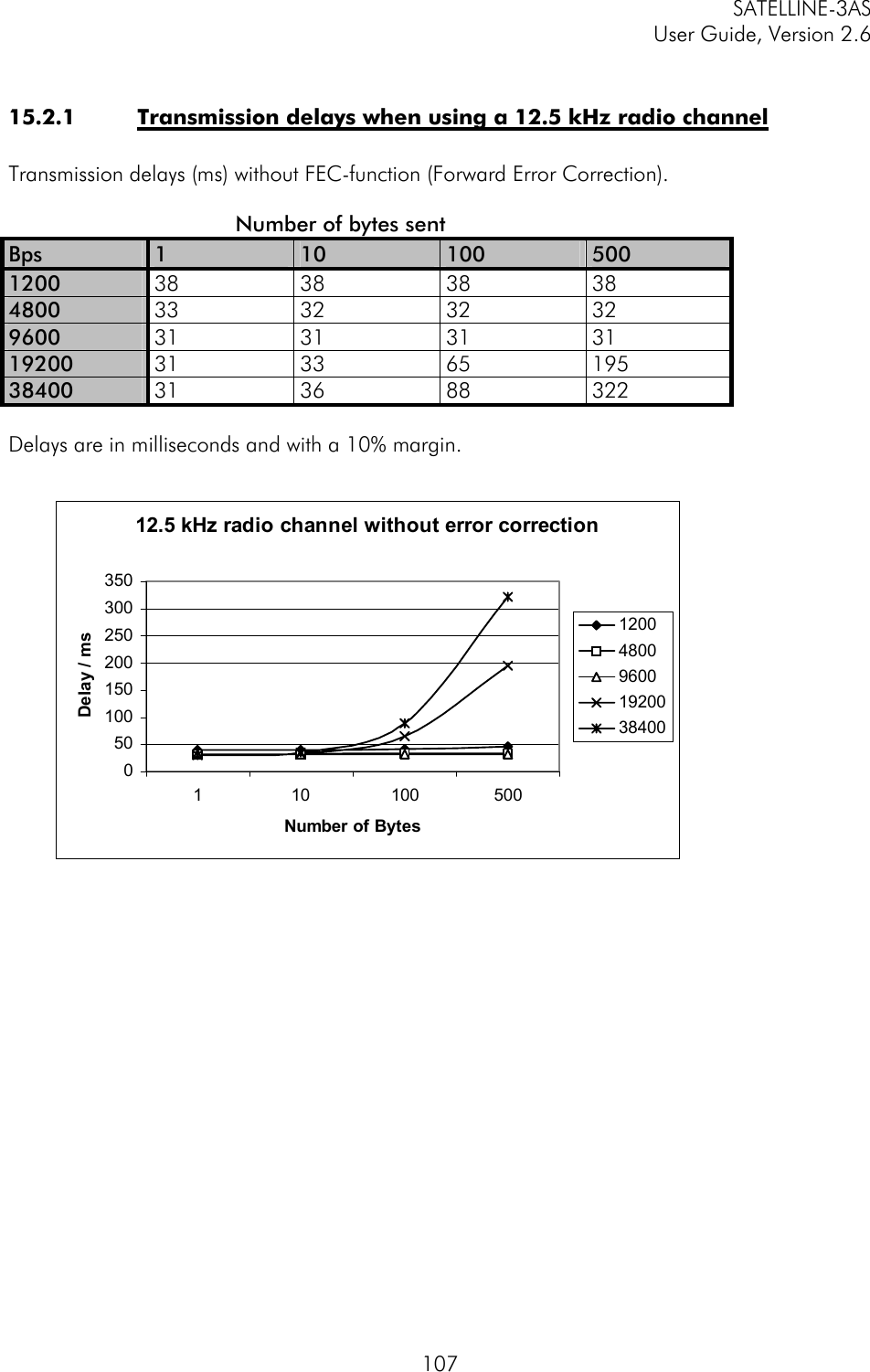
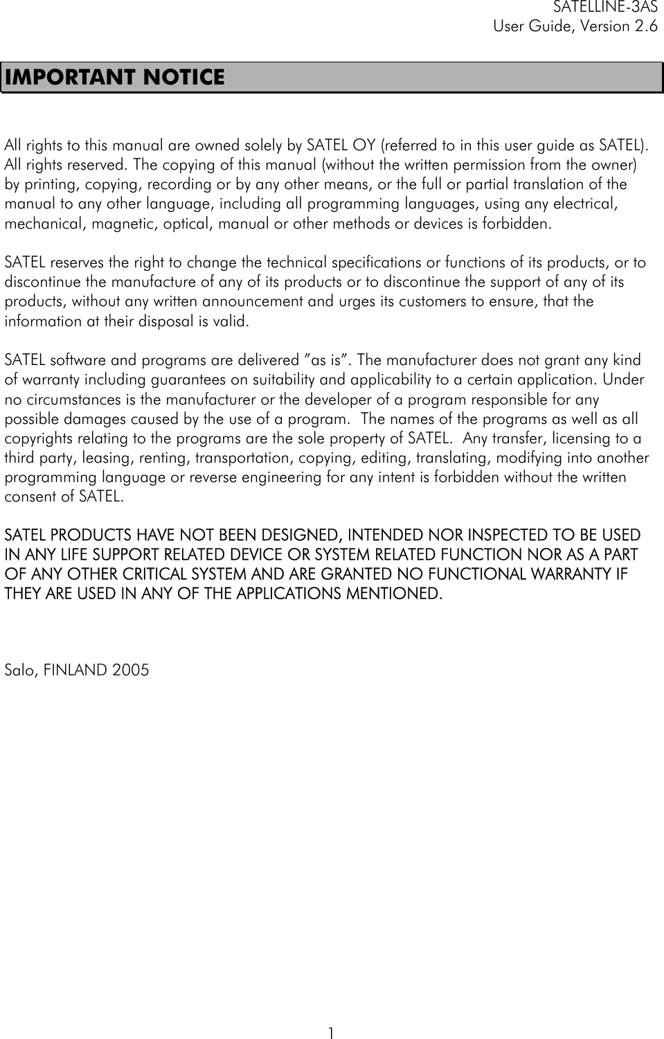
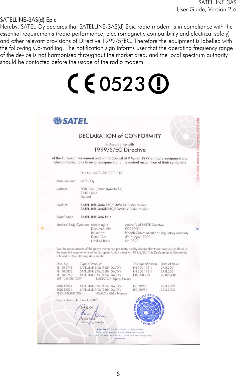
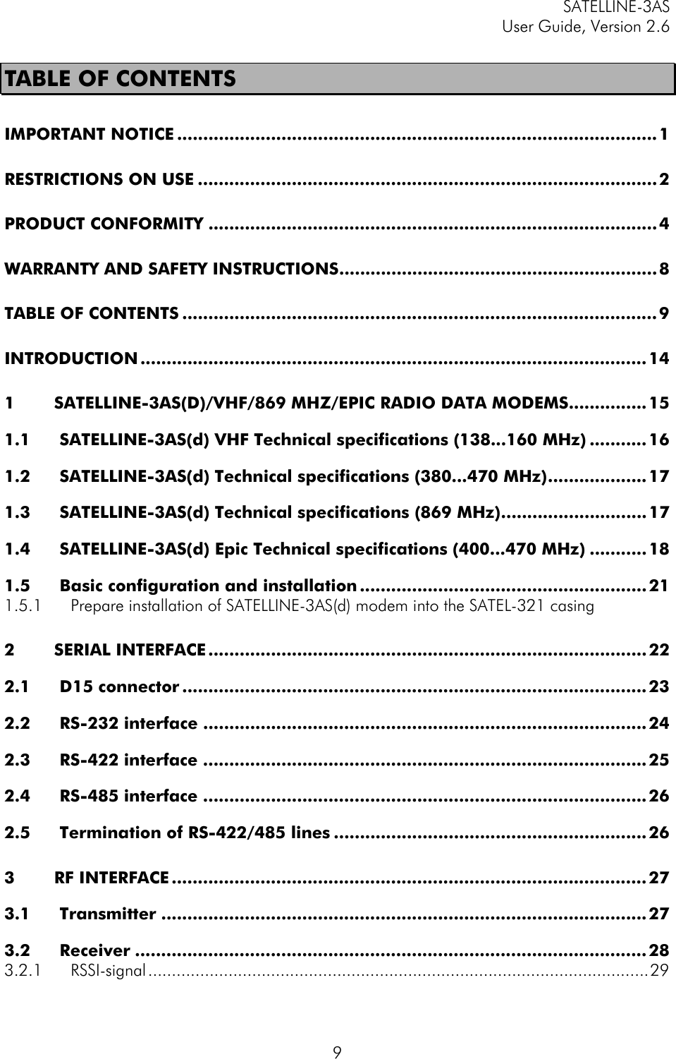
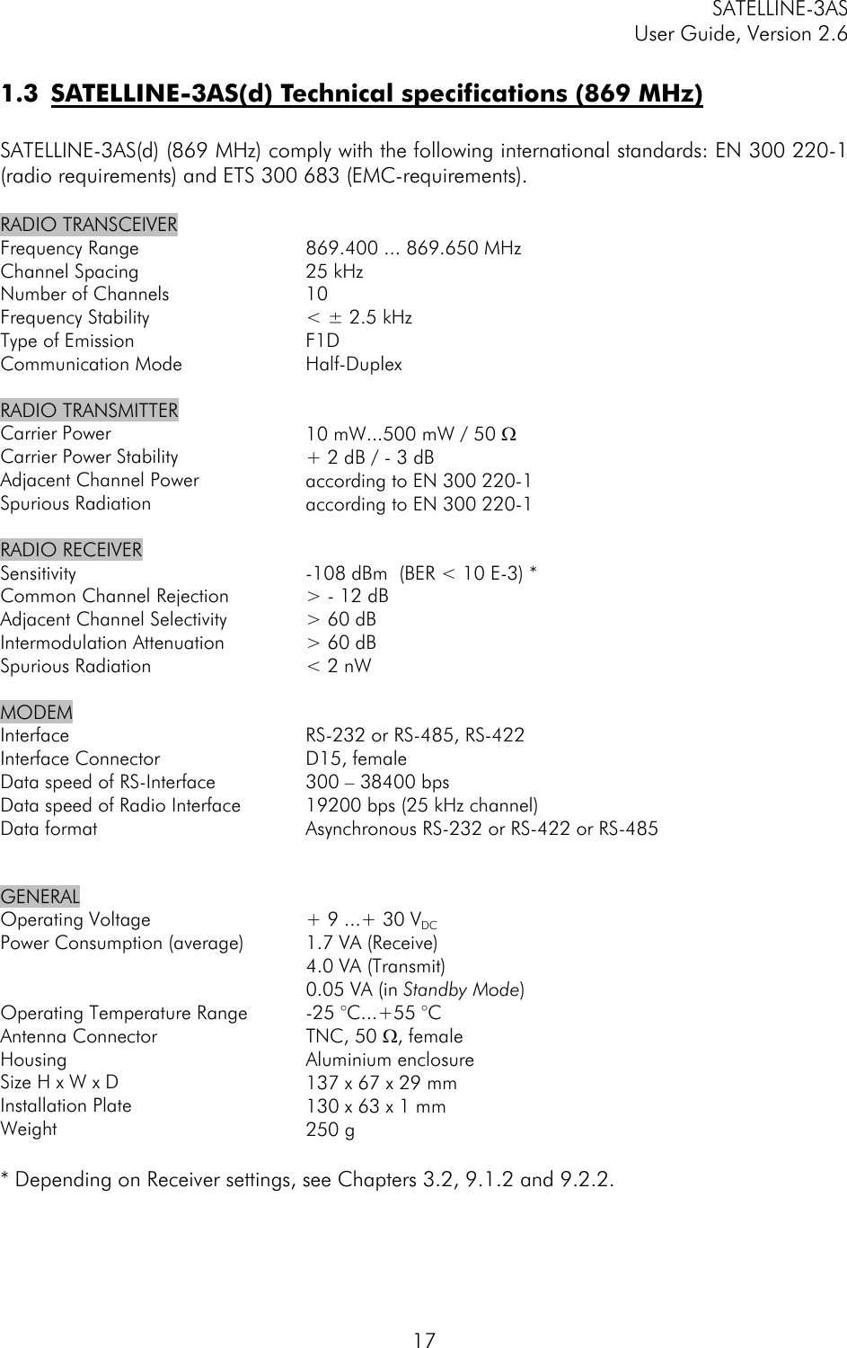
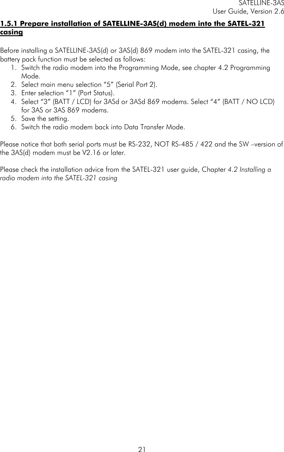
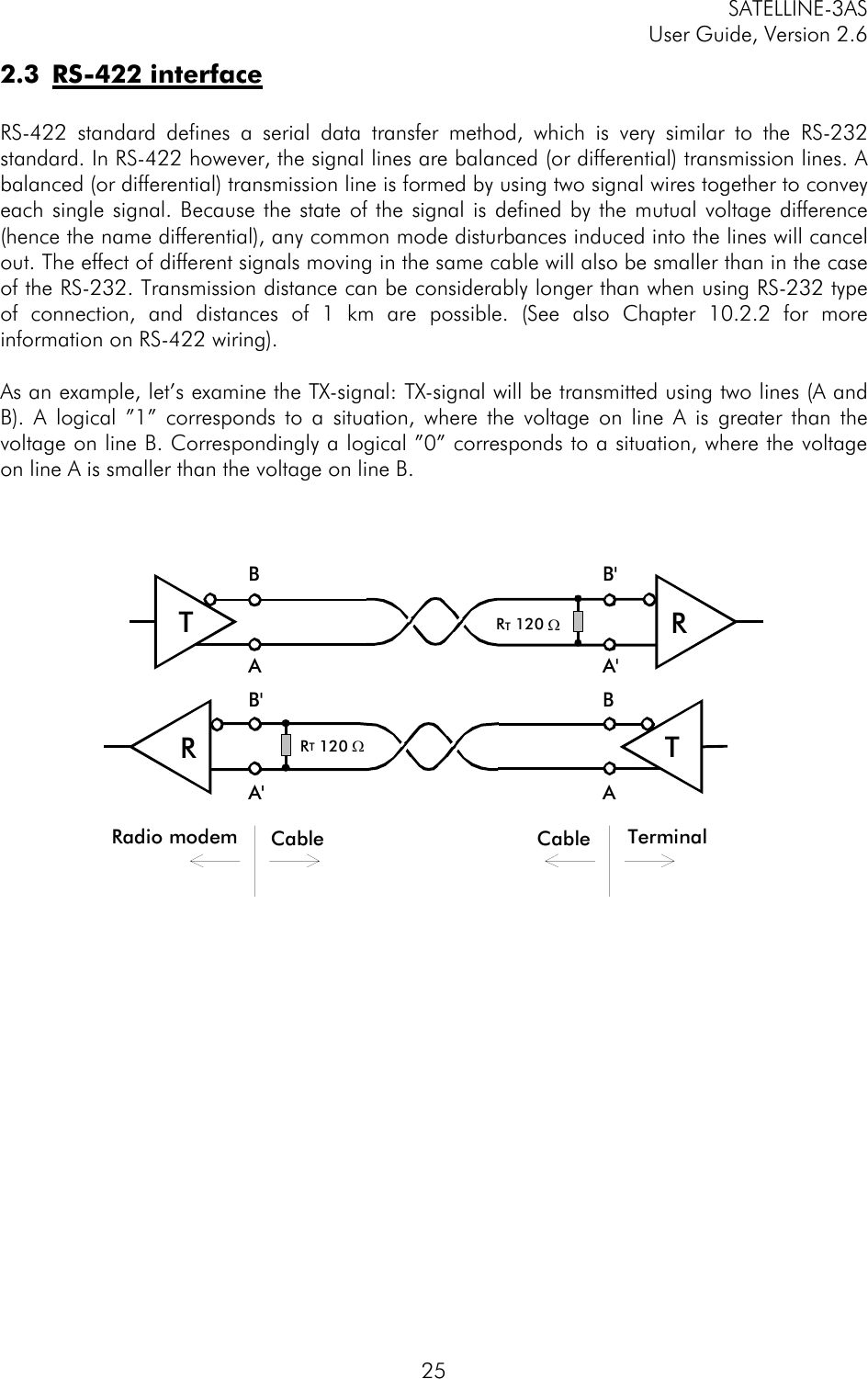
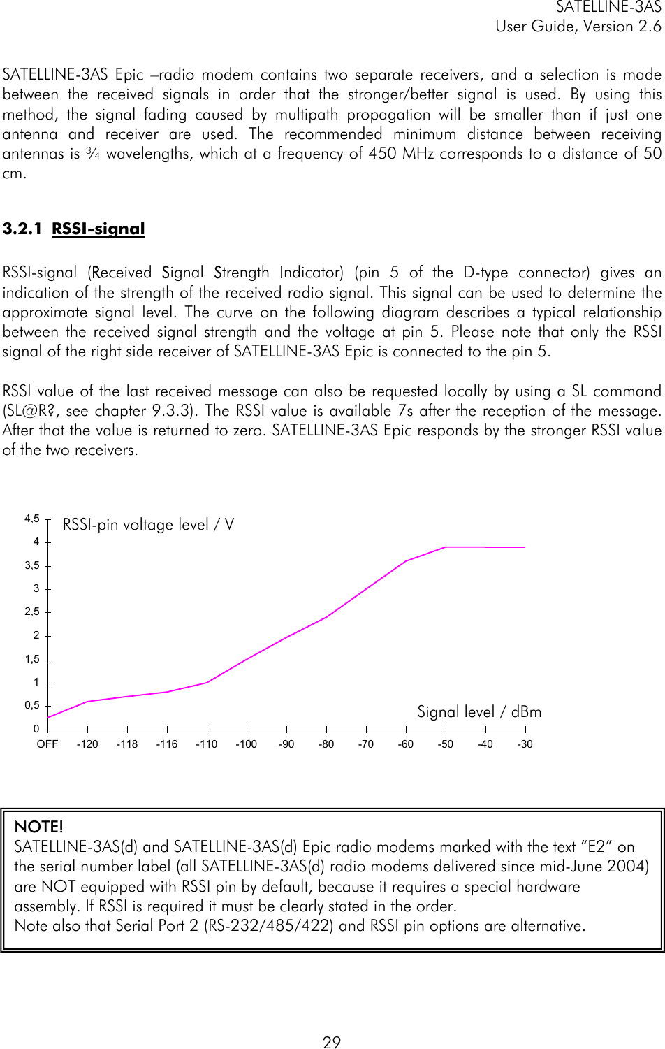
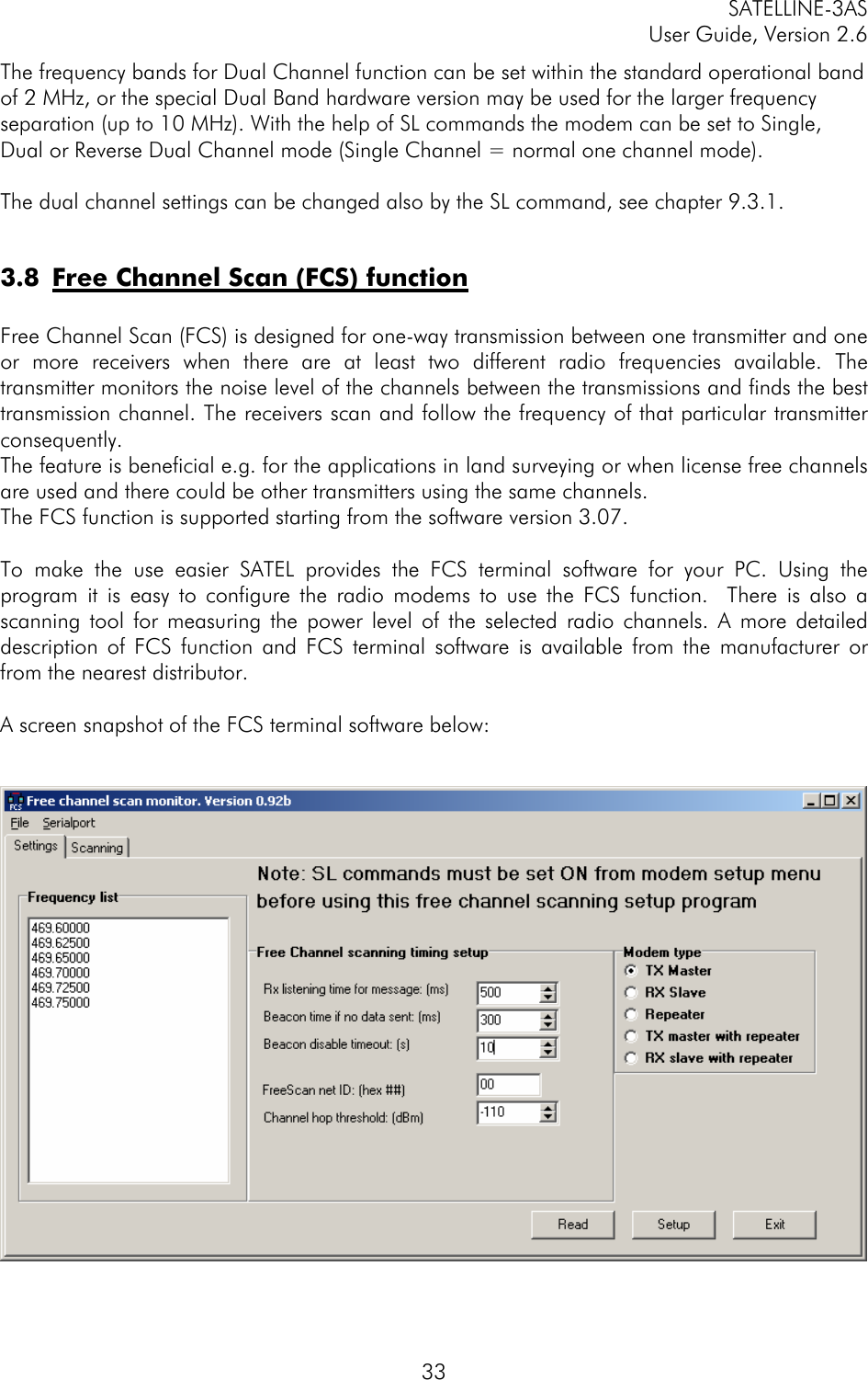
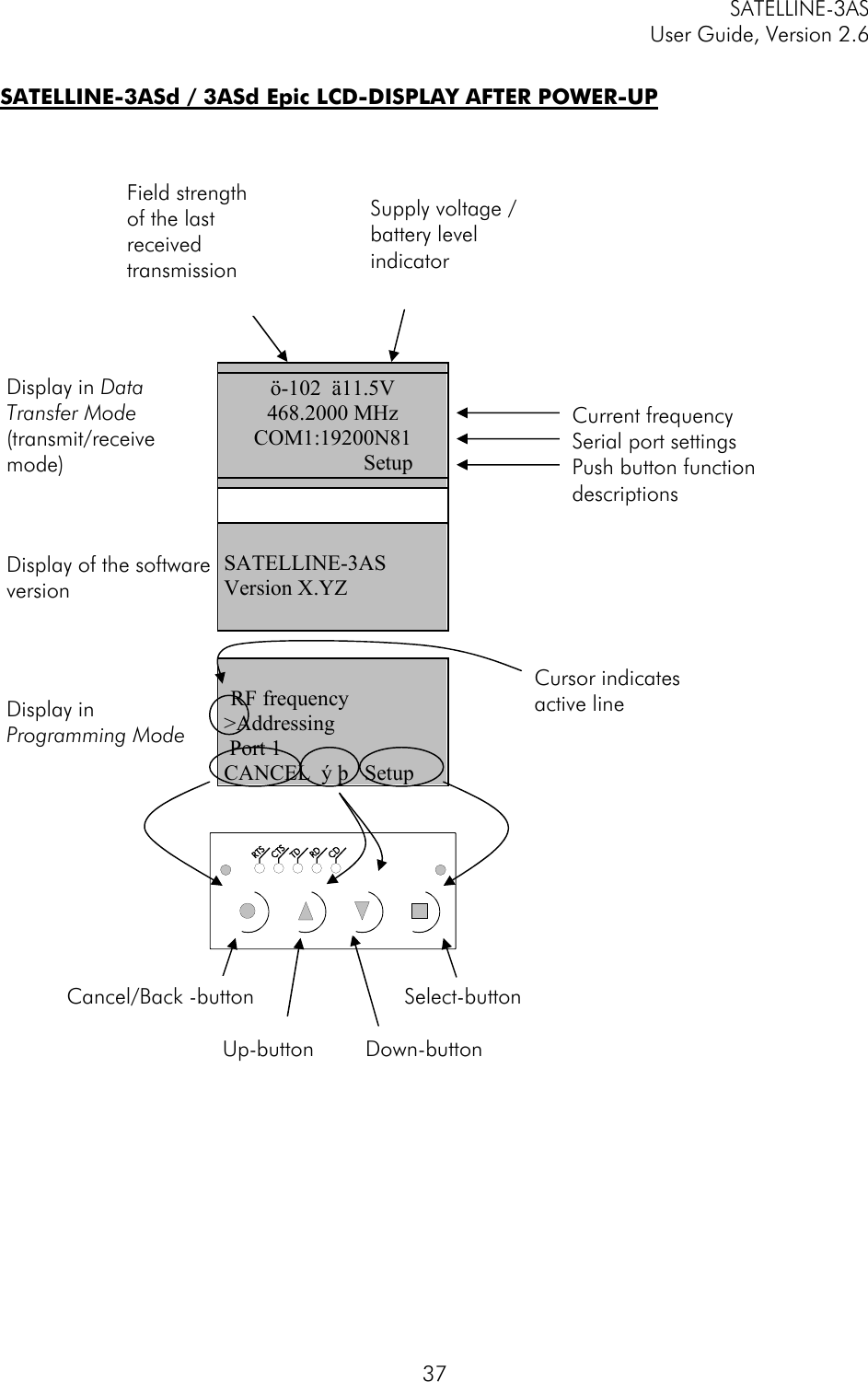
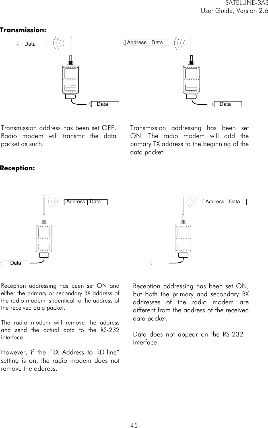
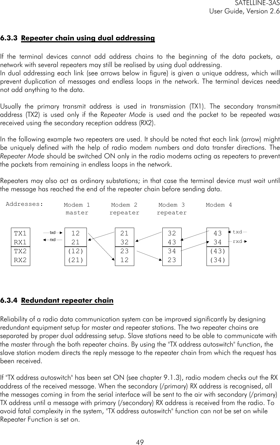
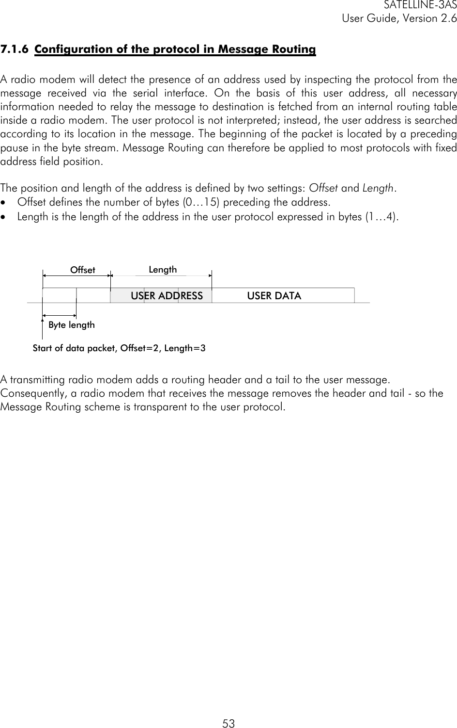
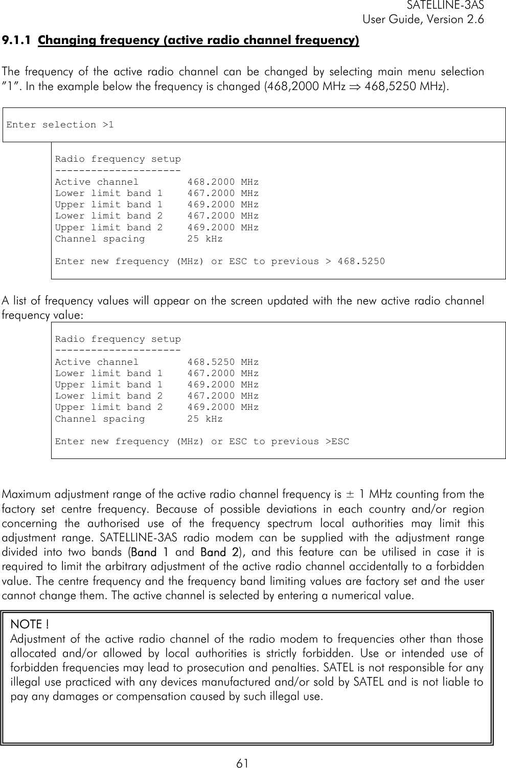
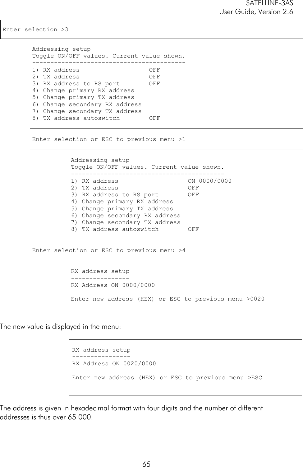
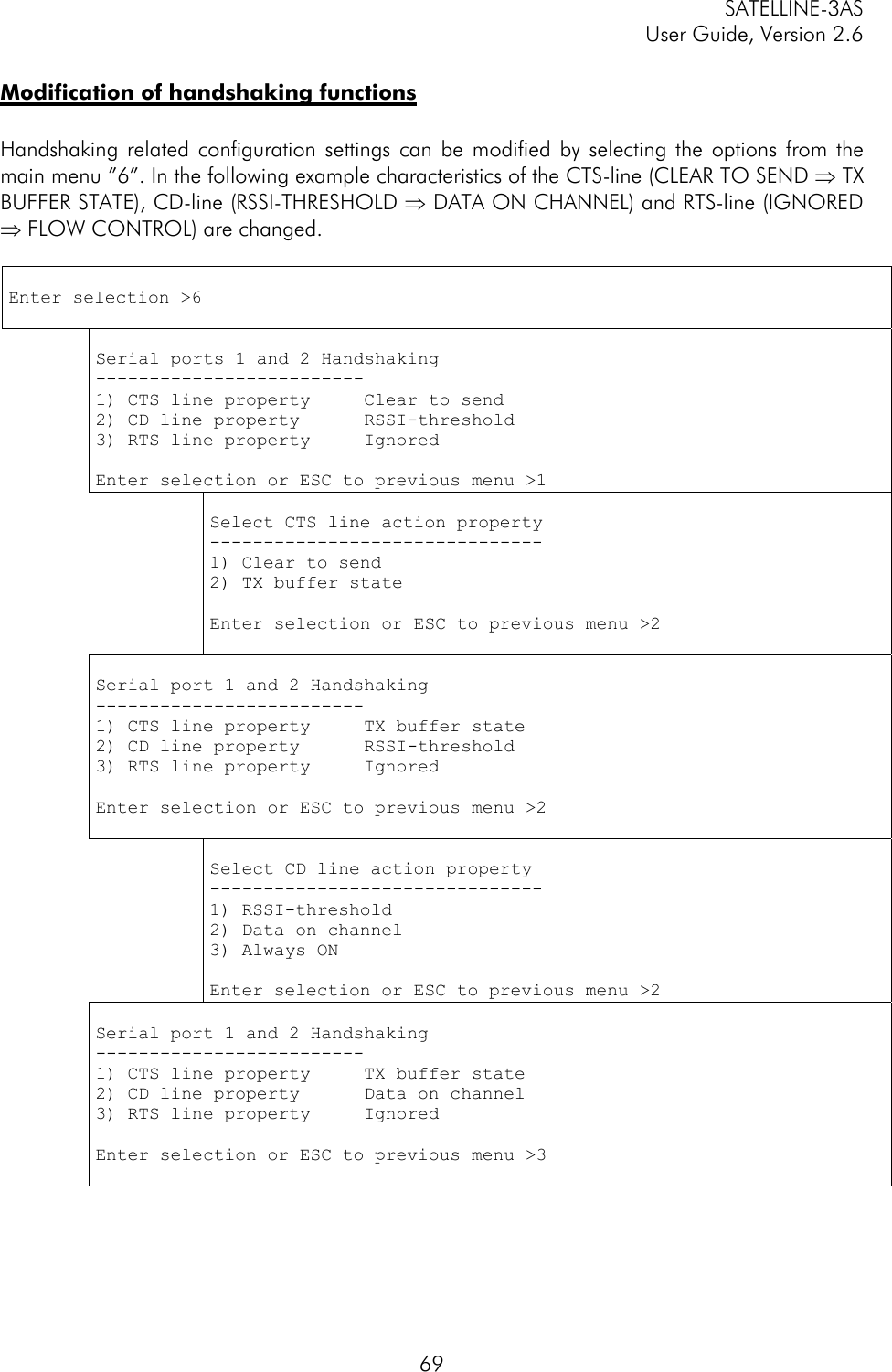
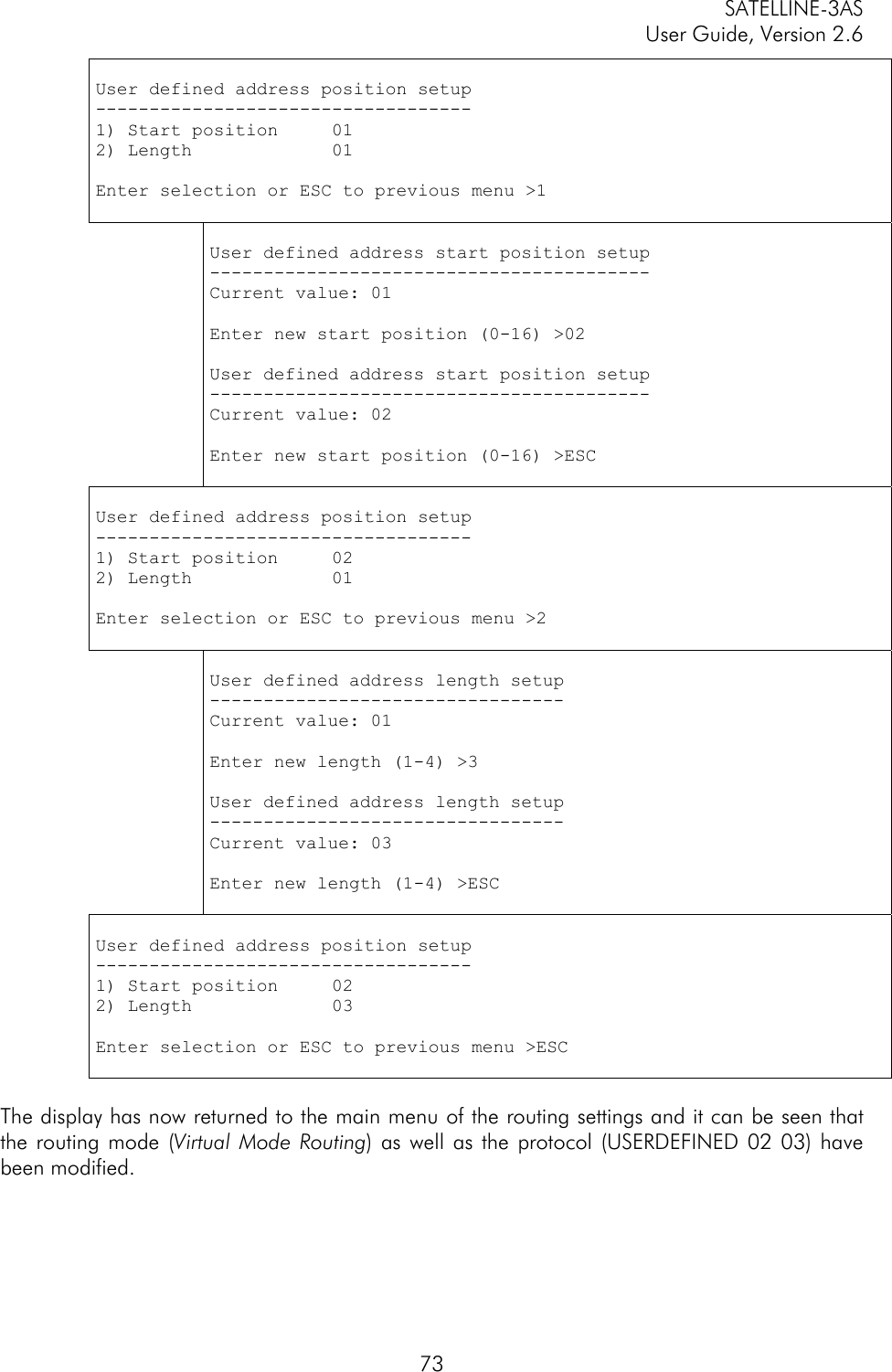
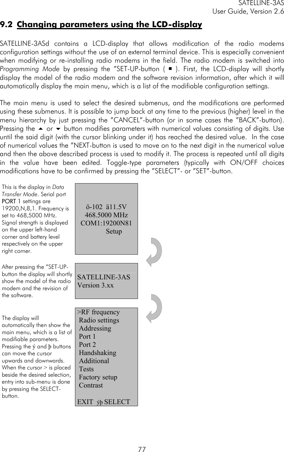
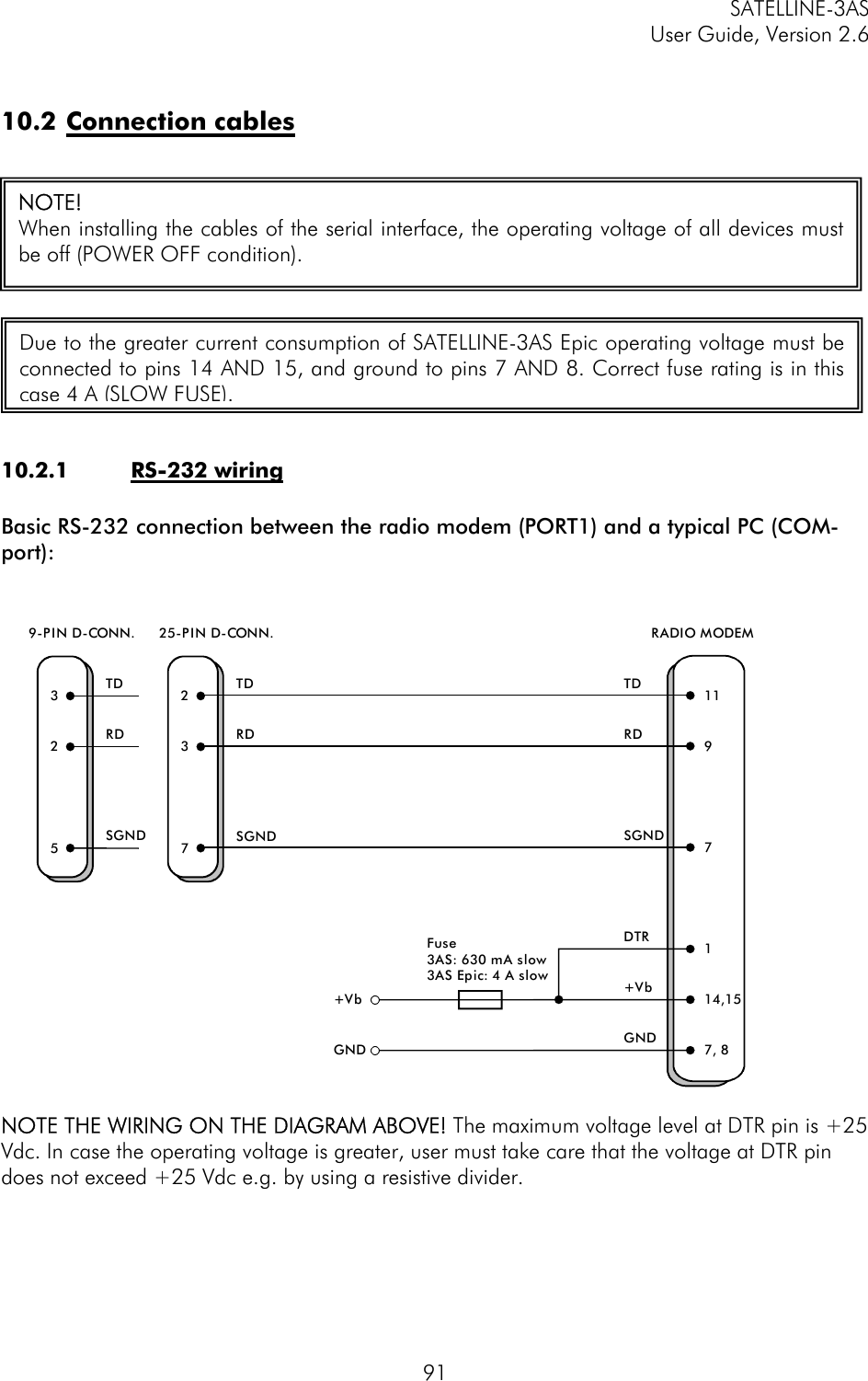
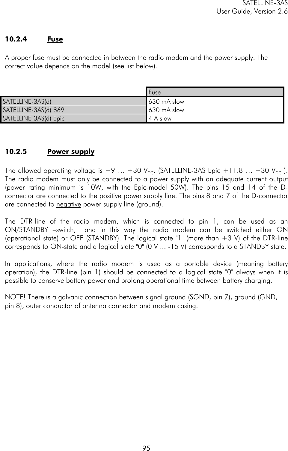
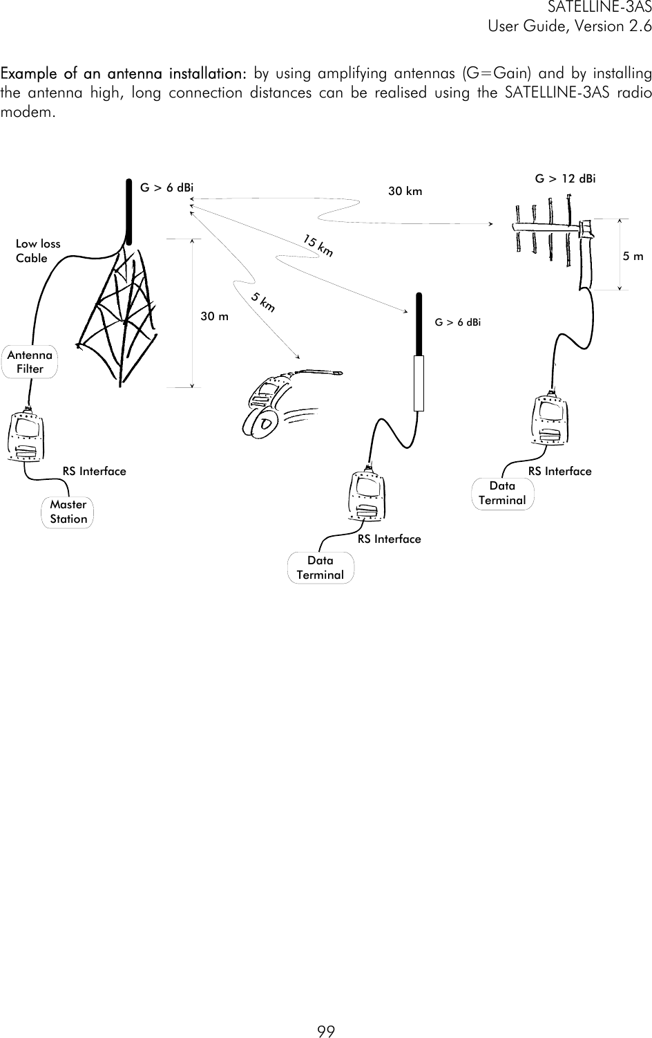
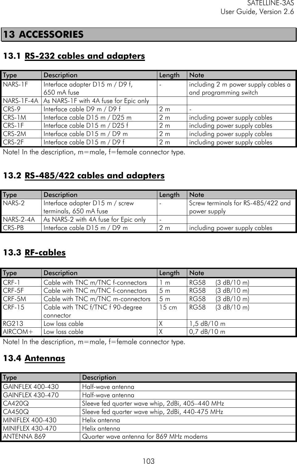
![SATELLINE-3AS User Guide, Version 2.6 899.3.5 SATELLINE-2ASxE compatible SL-commands The commands listed in the table below are included only to ensure compatibility and their use is not recommended in new networks. The commands do not need a CR-character (carriage return) at the end of the command string. Command Effect and description of command SLHxx Set frequency xx channels above center frequency. Frequency = Center frequency + xx*Channel spacing, where xx=[00…99] SLLxx Set frequency xx channels below center frequency. Frequency = Center frequency - xx*Channel spacing, where xx=[00…99] SLAxx Set all addresses (RX1, RX2, TX1, TX2) to value xx, where xx=[00h...FFh] SLTxx Set both transmit addresses (TX1, TX2) to value xx, where xx=[00h...FFh] SLRxx Set both receive addresses (RX1, RX2) to value xx, where xx=[00h...FFh] SLS0S Save current settings as permanent settings](https://usermanual.wiki/Satel/SATEL-3AS-VHF/User-Guide-587228-Page-89.png)
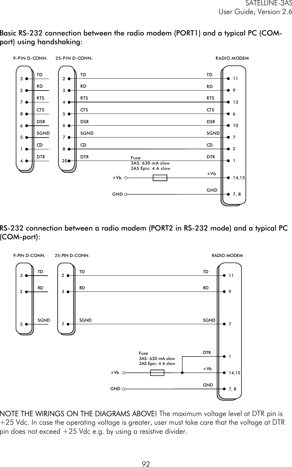
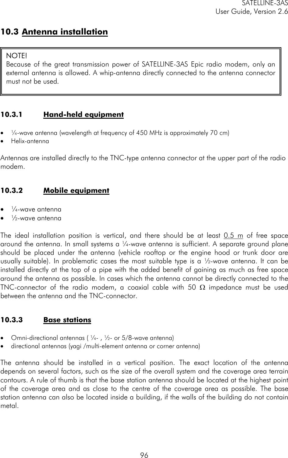
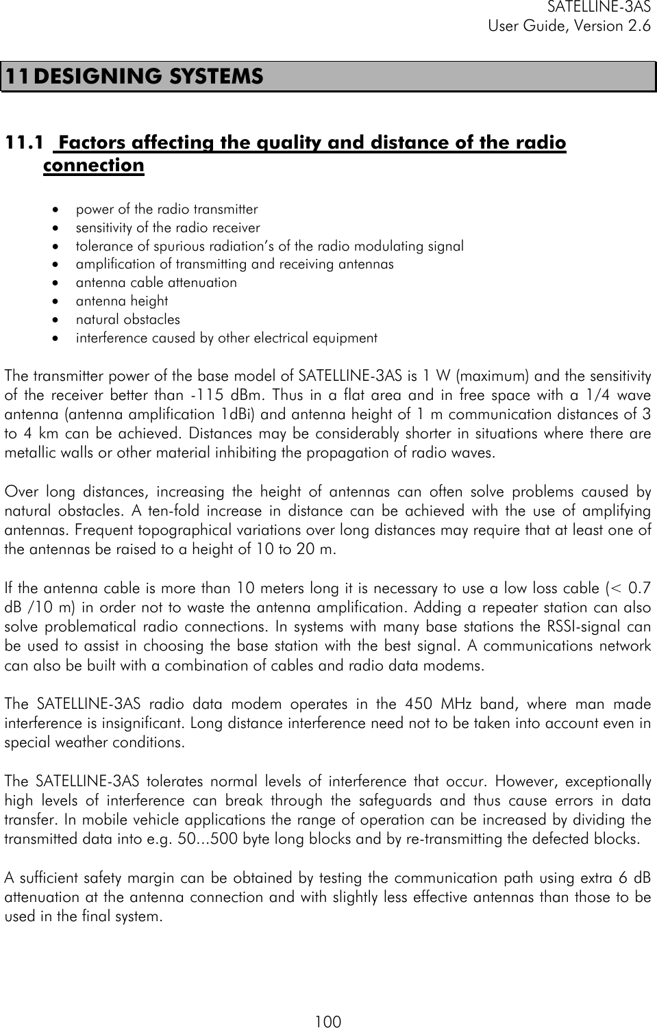
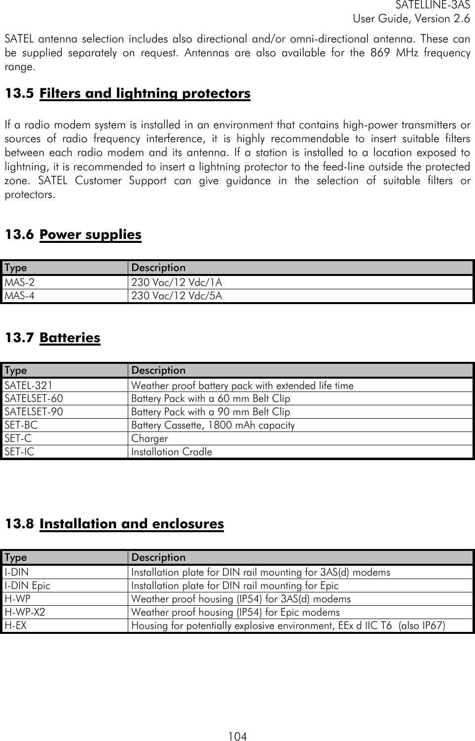
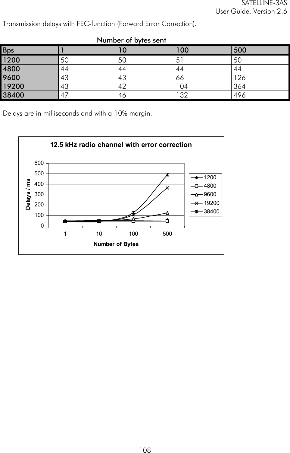
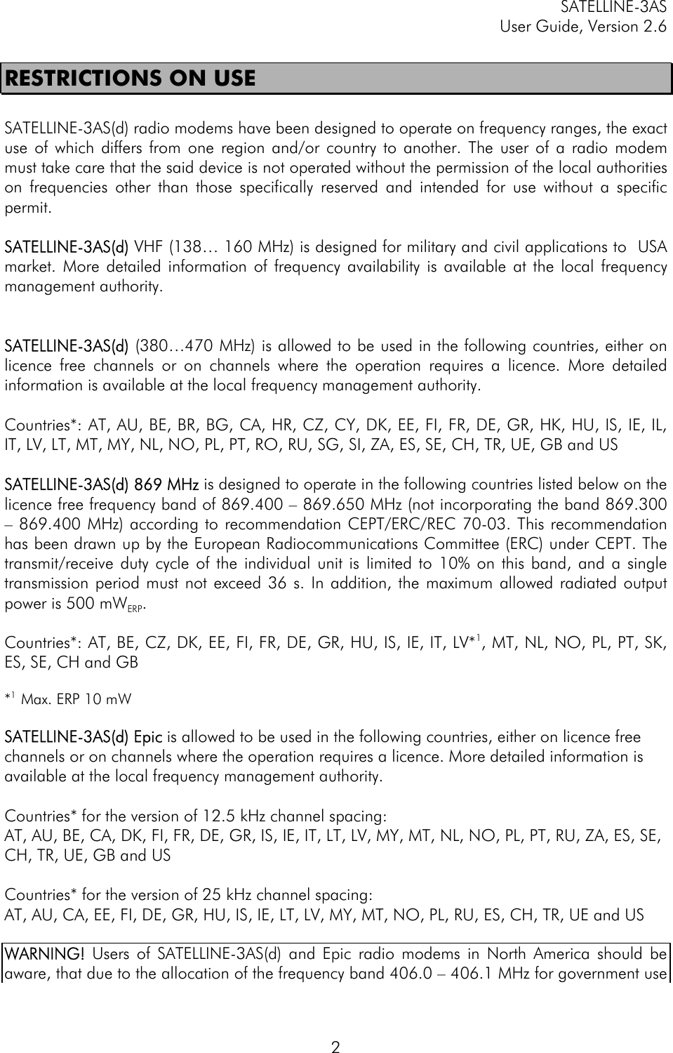
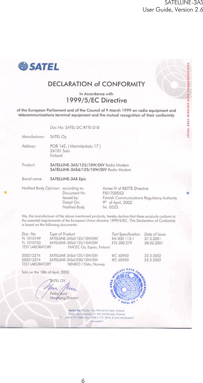
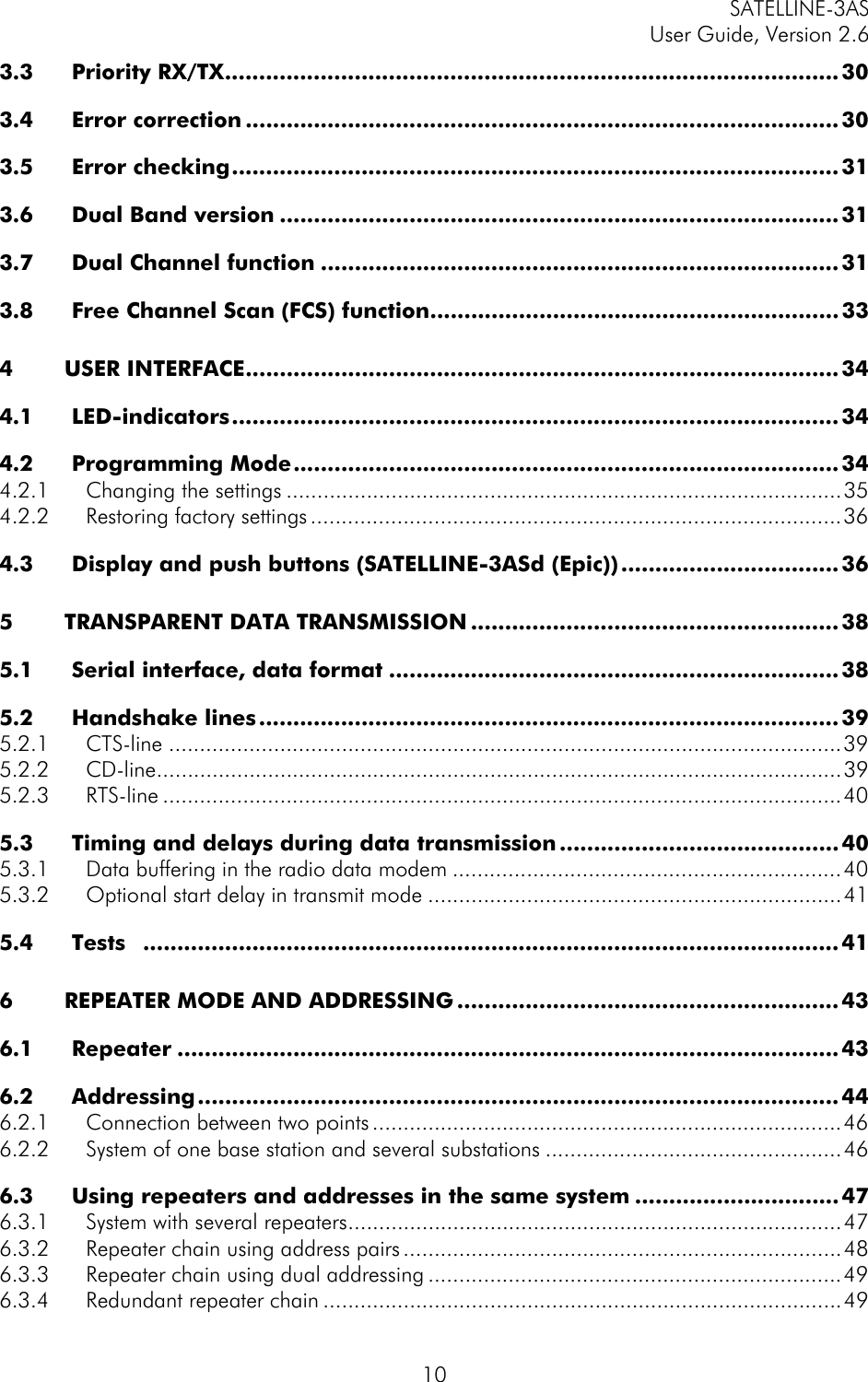
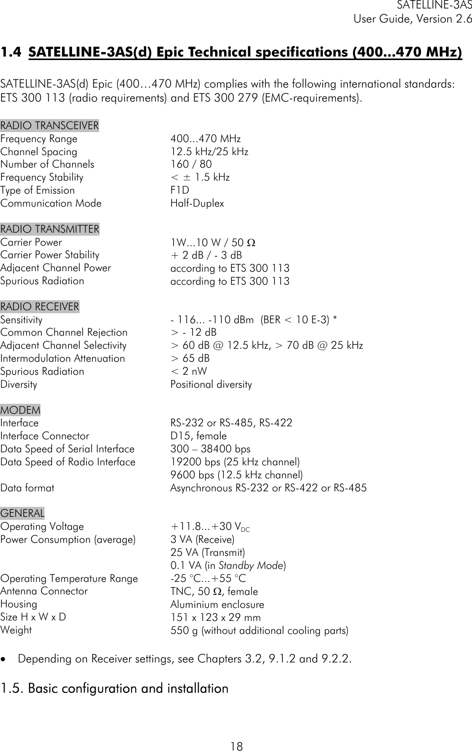
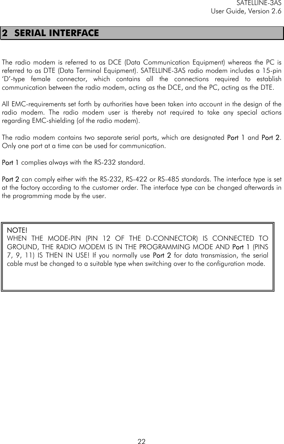
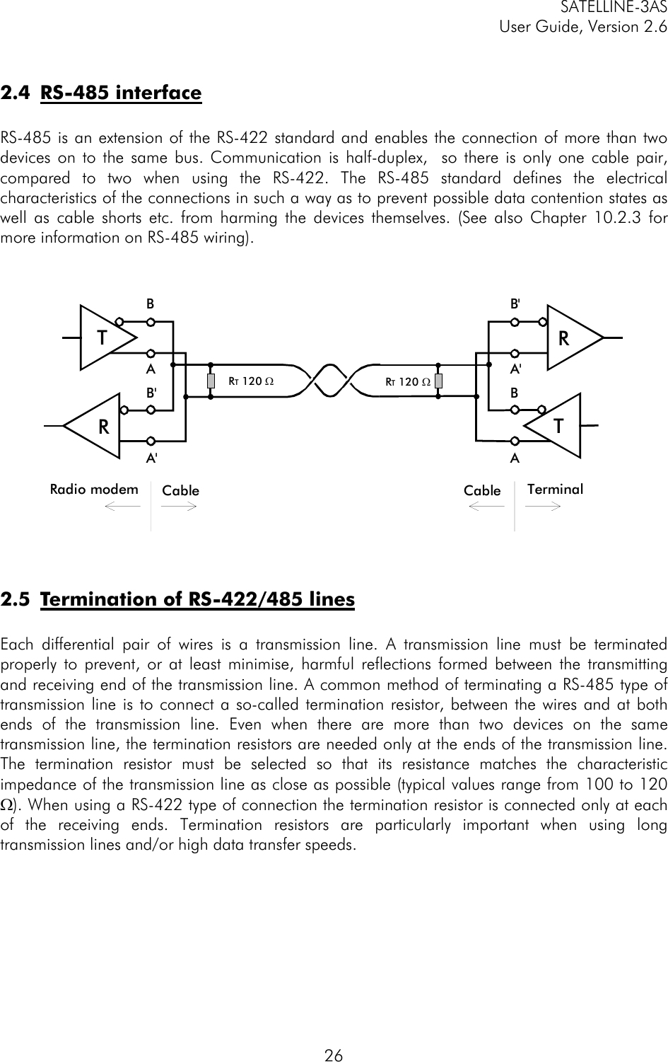
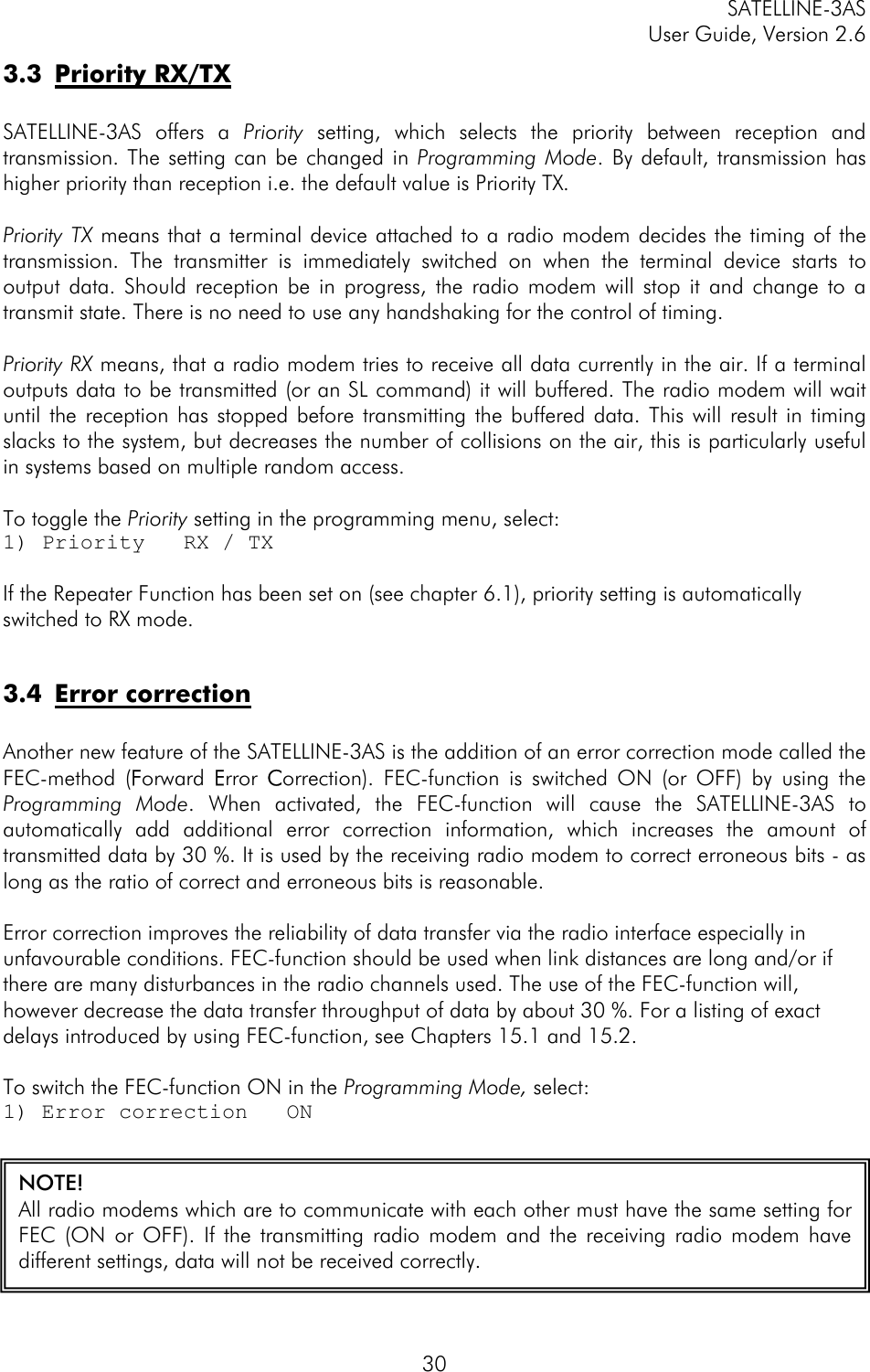
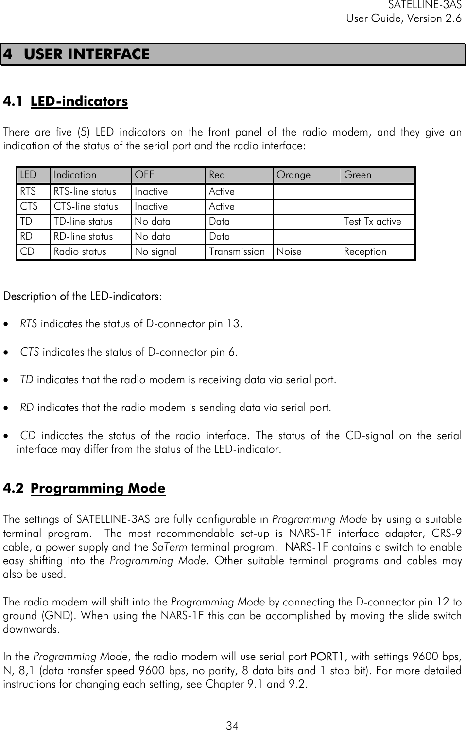
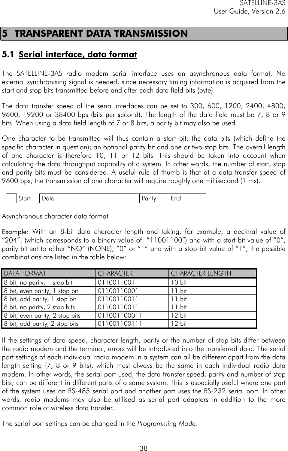
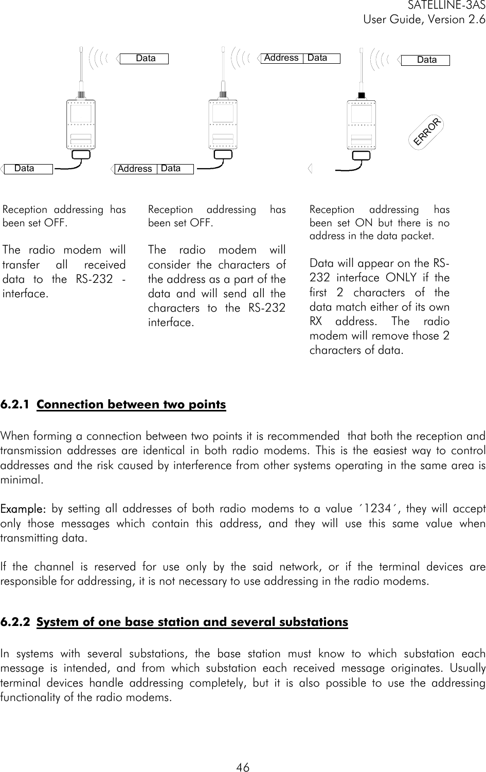
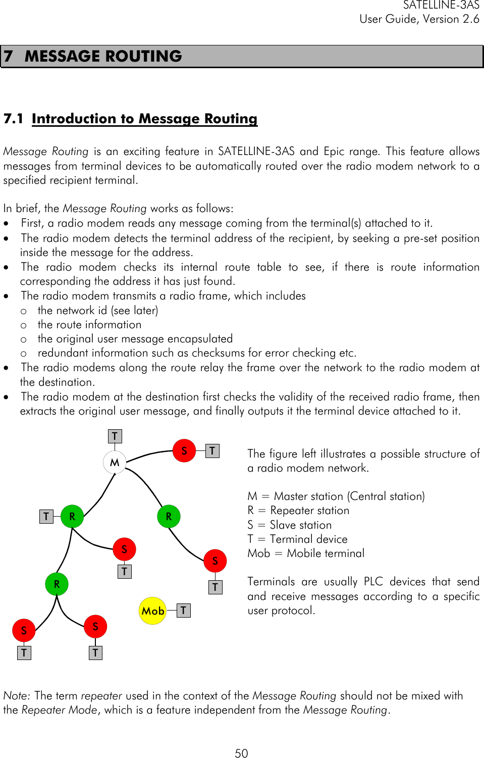
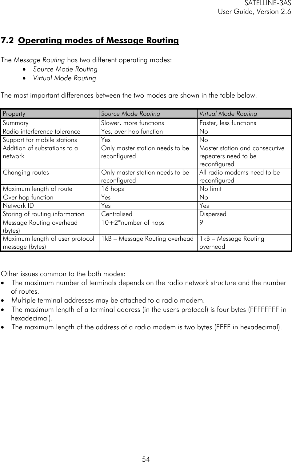
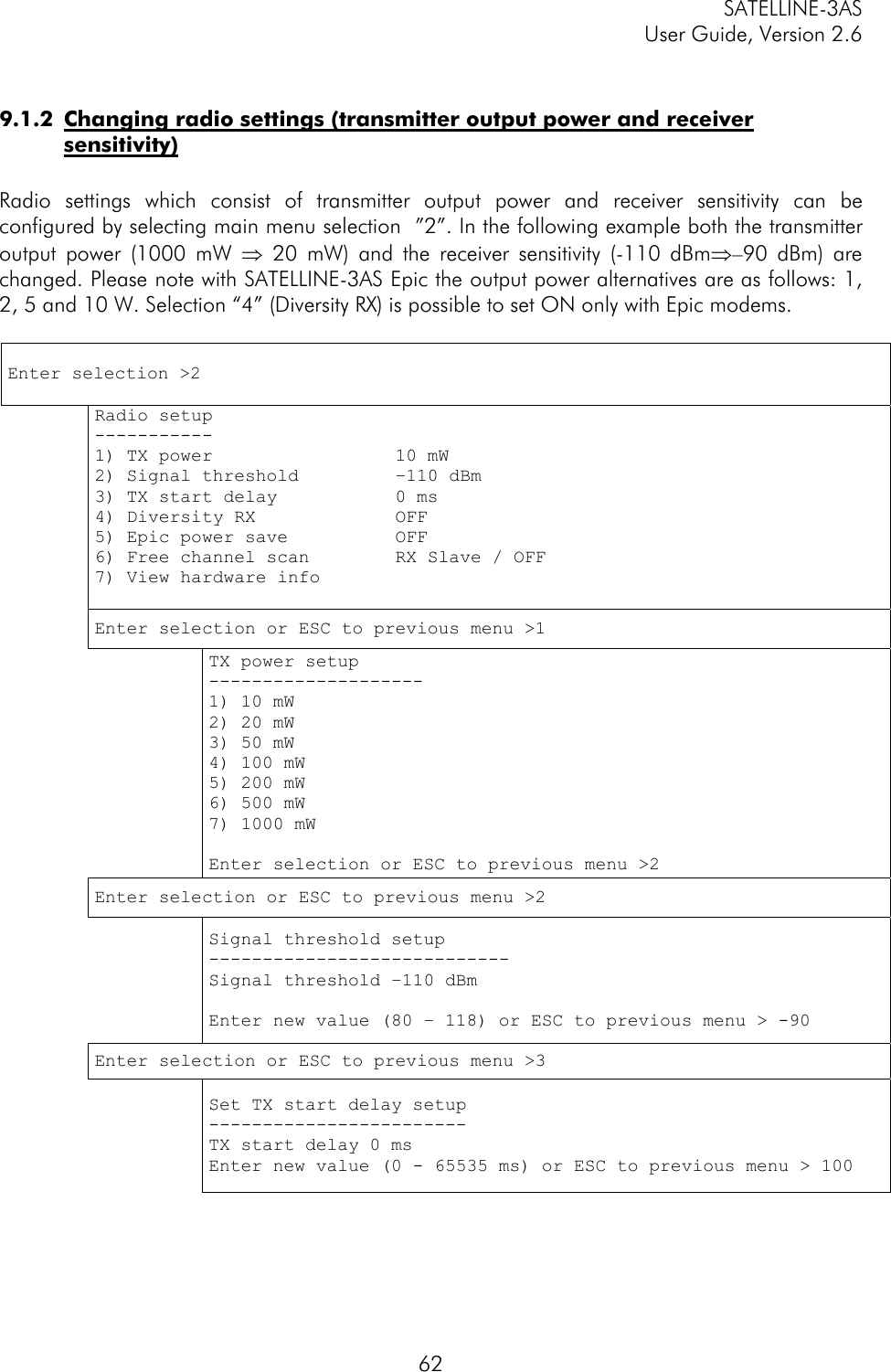
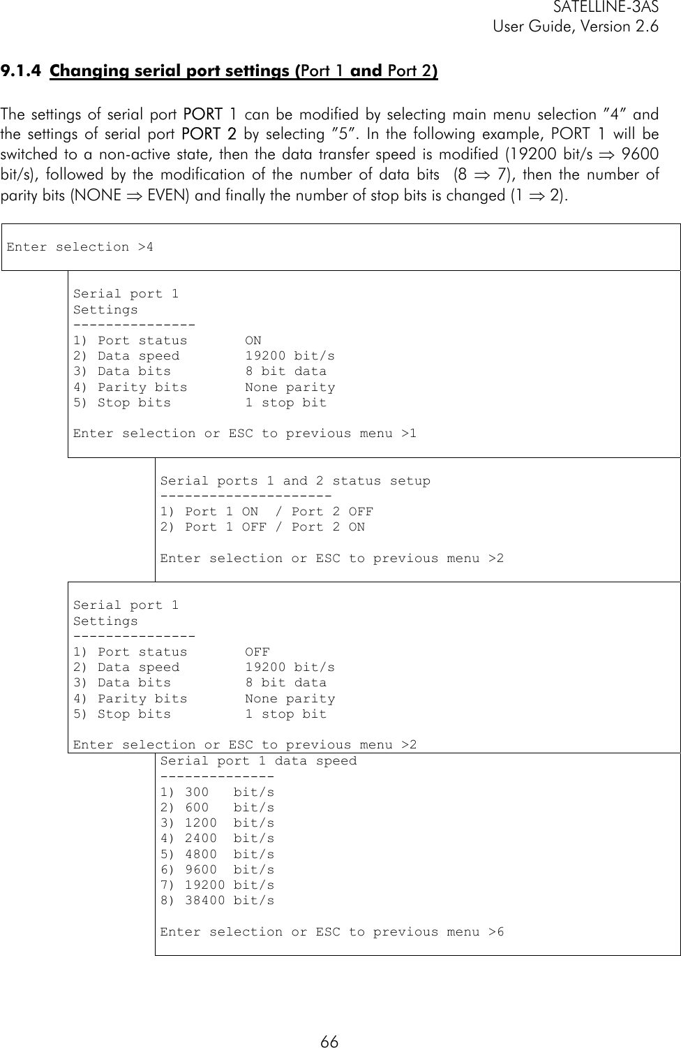
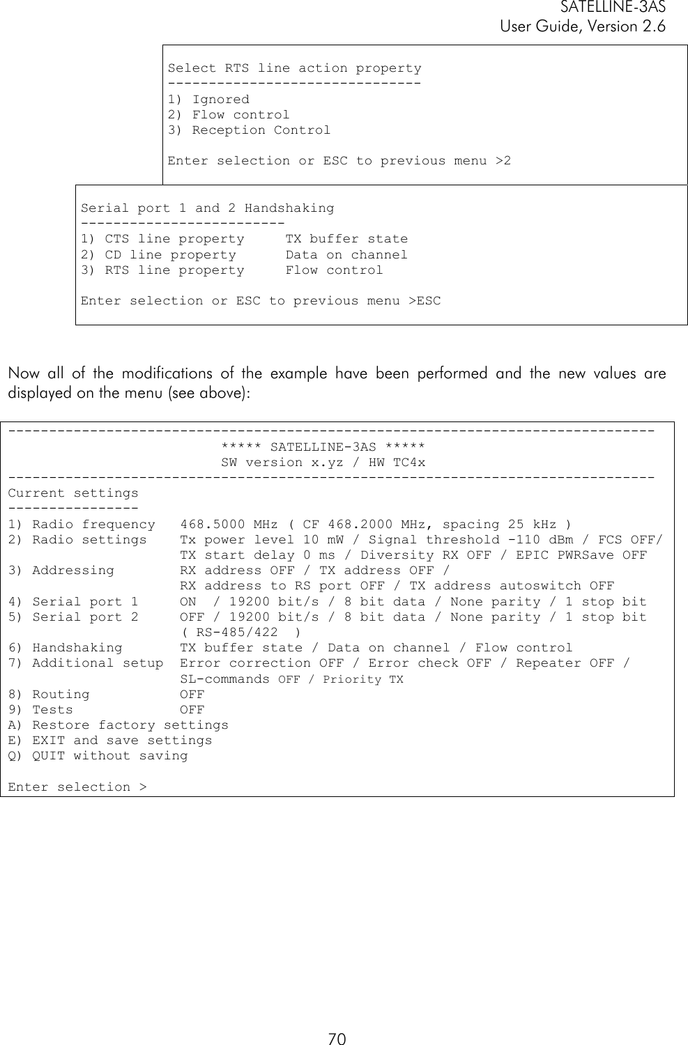
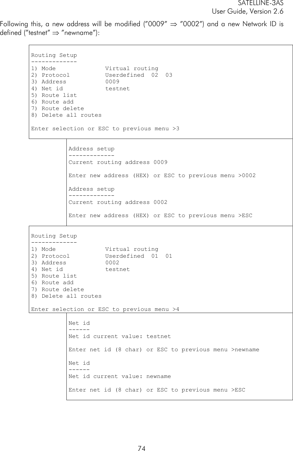
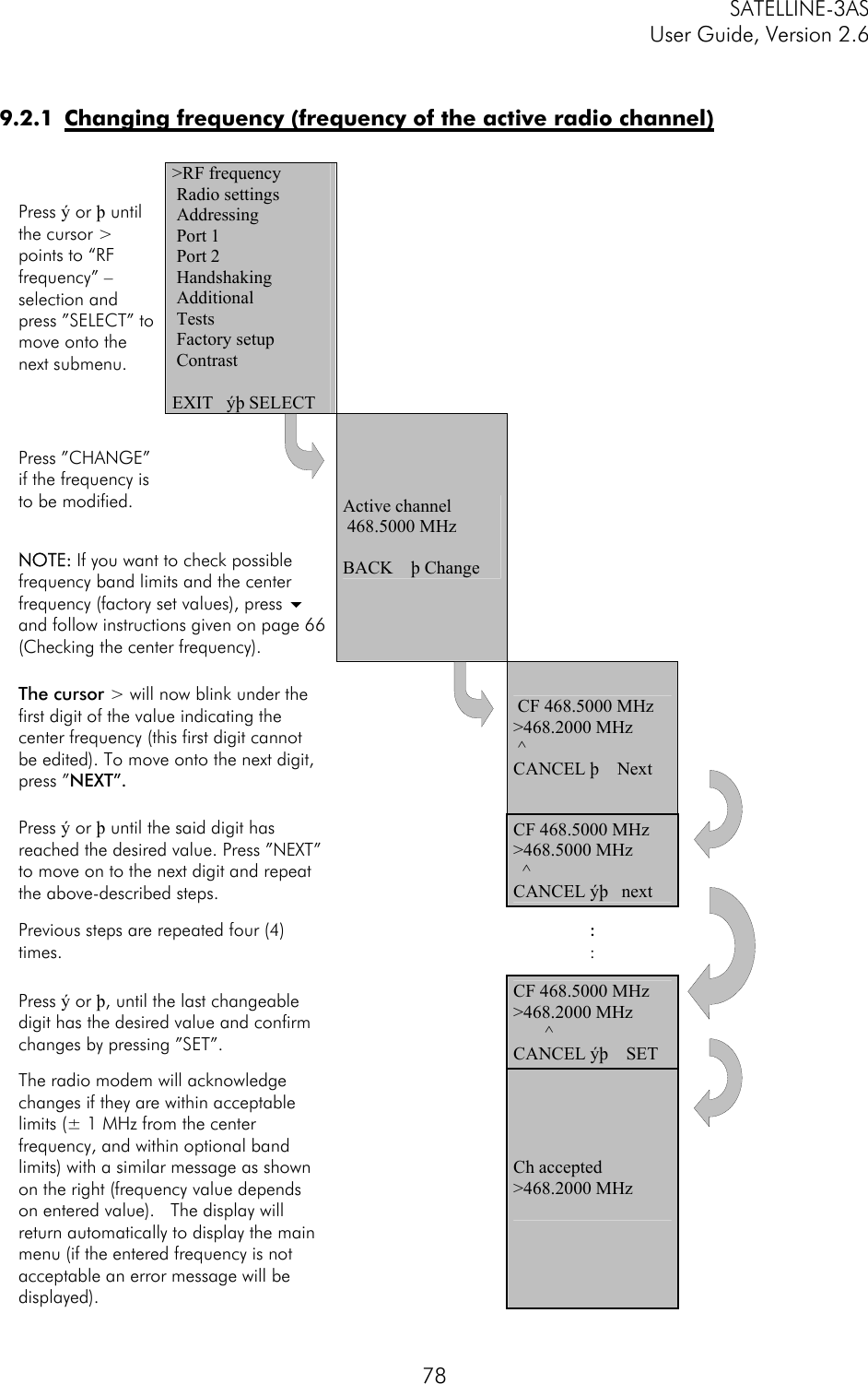
![SATELLINE-3AS User Guide, Version 2.6 10514 APPENDIX A ASCII CHARACTER TABLE D H A D H A D H A D H A D H A D H A 0 0 NUL 43 2B + 86 56 V 129 81 172 AC 215 D7 1 1 SOH 44 2C , 87 57 W 130 82 173 AD 216 D8 2 2 STX 45 2D - 88 58 X 131 83 174 AE 217 D9 3 3 ETX 46 2E . 89 59 Y 132 84 175 AF 218 DA 4 4 EOT 47 2F / 90 5A Z 133 85 176 B0 219 DB 5 5 ENQ 48 30 0 91 5B [ 134 86 177 B1 220 DC 6 6 ACK 49 31 1 92 5C \ 135 87 178 B2 221 DD 7 7 BEL 50 32 2 93 5D ] 136 88 179 B3 222 DE 8 8 BS 51 33 3 94 5E ^ 137 89 180 B4 223 DF 9 9 HT 52 34 4 95 5F _ 138 8A 181 B5 224 E0 10 A LF 53 35 5 96 60 ` 139 8B 182 B6 225 E1 11 B VT 54 36 6 97 61 a 140 8C 183 B7 226 E2 12 C FF 55 37 7 98 62 b 141 8D 184 B8 227 E3 13 D CR 56 38 8 99 63 c 142 8E 185 B9 228 E4 14 E SO 57 39 9 100 64 d 143 8F 186 BA 229 E5 15 F SI 58 3A : 101 65 e 144 90 187 BB 230 E6 16 10 DLE 59 3B ; 102 66 f 145 91 188 BC 231 E7 17 11 DC1 60 3C < 103 67 g 146 92 189 BD 232 E8 18 12 DC2 61 3D = 104 68 h 147 93 190 BE 233 E9 19 13 DC3 62 3E > 105 69 i 148 94 191 BF 234 EA 20 14 DC4 63 3F ? 106 6A j 149 95 192 C0 235 EB 21 15 NAK 64 40 @ 107 6B k 150 96 193 C1 236 EC 22 16 SYN 65 41 A 108 6C l 151 97 194 C2 237 ED 23 17 ETB 66 42 B 109 6D m 152 98 195 C3 238 EE 24 18 CAN 67 43 C 110 6E n 153 99 196 C4 239 EF 25 19 EM 68 44 D 111 6F o 154 9A 197 C5 240 F0 26 1A SUB 69 45 E 112 70 p 155 9B 198 C6 241 F1 27 1B ESC 70 46 F 113 71 q 156 9C 199 C7 242 F2 28 1C FS 71 47 G 114 72 r 157 9D 200 C8 243 F3 29 1D GS 72 48 H 115 73 s 158 9E 201 C9 244 F4 30 1E RS 73 49 I 116 74 t 159 9F 202 CA 245 F5 31 1F US 74 4A J 117 75 u 160 A0 203 CB 246 F6 32 20 SP 75 4B K 118 76 v 161 A1 204 CC 247 F7 33 21 ! 76 4C L 119 77 w 162 A2 205 CD 248 F8 34 22 " 77 4D M 120 78 x 163 A3 206 CE 249 F9 35 23 # 78 4E N 121 79 y 164 A4 207 CF 250 FA 36 24 $ 79 4F O 122 7A z 165 A5 208 D0 251 FB 37 25 % 80 50 P 123 7B { 166 A6 209 D1 252 FC 38 26 & 81 51 Q 124 7C | 167 A7 210 D2 253 FD 39 27 ' 82 52 R 125 7D } 168 A8 211 D3 254 FE 40 28 ( 83 53 S 126 7E ~ 169 A9 212 D4 255 FF 41 29 ) 84 54 T 127 7F 170 AA 213 D5 42 2A * 85 55 U 128 80 171 AB 214 D6](https://usermanual.wiki/Satel/SATEL-3AS-VHF/User-Guide-587228-Page-105.png)