Satel SATEL-TA10 SATELLINE-M3-R1 / SLR2 User Manual SATELLINE 3AS SLR UserGuide V3 6
Satel Oy SATELLINE-M3-R1 / SLR2 SATELLINE 3AS SLR UserGuide V3 6
UserManual.wiki
>
Satel
>
SATEL-TA10 User Manual
>
user manual
Contents
1.
user manual
2.
warning statements
user manual
Navigation menu
Upload a User Manual
Namespaces
Wiki Guide
HTML
PDF
Info
Views
User Manual
Discussion / Help
Navigation

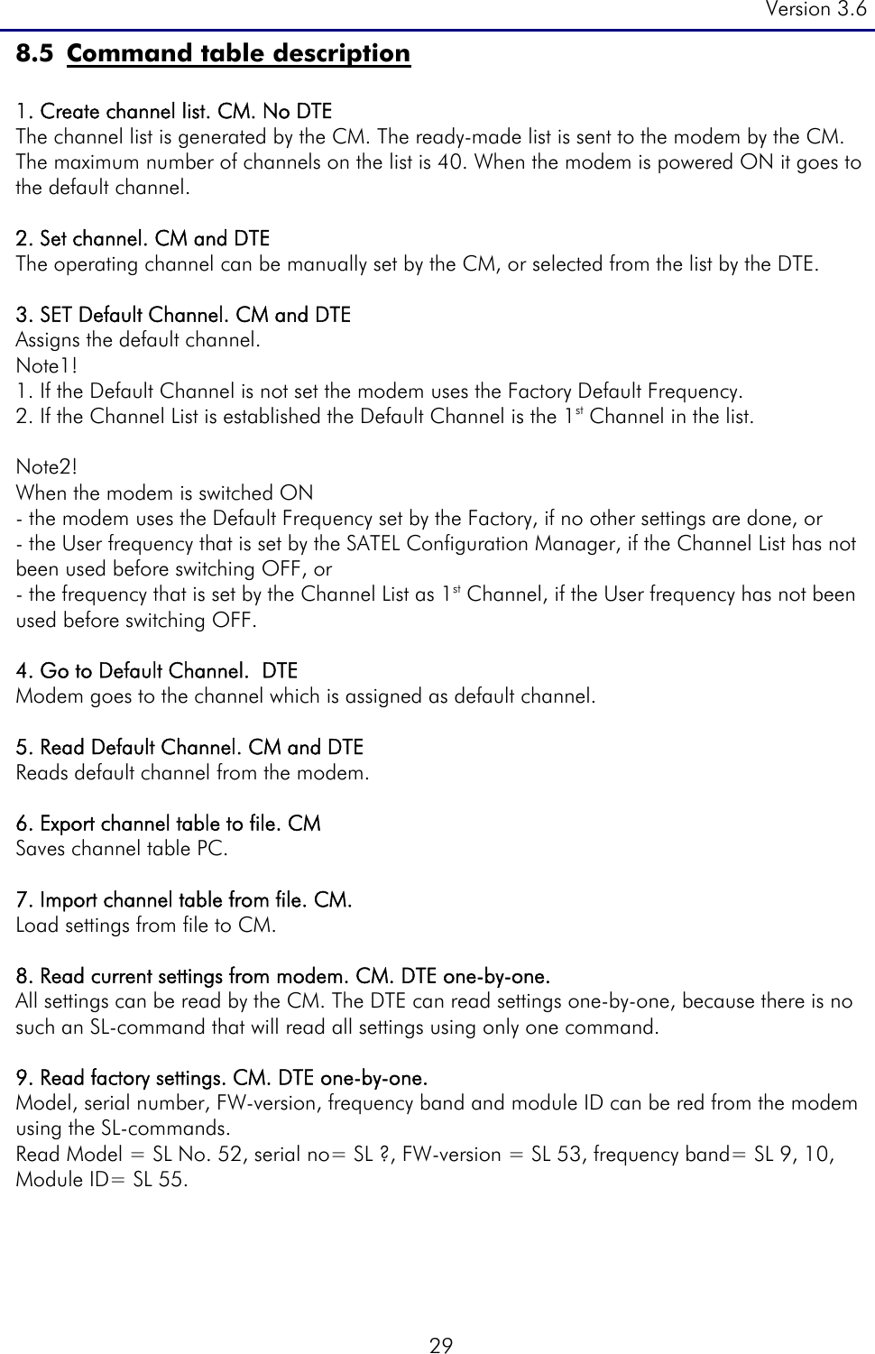
![Version 3.6 32 32.3 Set Option1 This Option is 4FSK-mode. When this mode is used the other values are must be: SATEL Modem PCC Modem FEC: OFF Forward Error Correction: ON Baud Rate: 19200 Scrambling: ON Addressing: Not available Protocol Mode: Transparent Mode w/EOT Timeout 32.4 Set Option2 This Option is GMSK-mode When this mode is used the other values are must be: SATEL Modem PCC Modem FEC: OFF Forward Error Correction: ON Baud Rate: 9600 Scrambling: ON Addressing: Not available Protocol Mode: Transparent Mode w/EOT Timeout 32.5 Read Option Read the current Option The Modem retrieves: “0” when in 3AS-mode. “1” when in Option 1-mode. “2” when in Option 2-mode. 33. Set RSSI-threshold. CM. Sets the RSSI-signal threshold level. The RSSI Signal Threshold setting of the receiver determines the level that the modem operates properly. The number is shown as [–dBm], so the greater the number is the weaker is the signal threshold level (-100 dBm is weaker than -90 dBm). The modem operates only, if the received signal is stronger than the Signal Threshold level. When set, it applies to all channels and frequencies. If the environment is noisy and it is needed that the modem does not listen to noisy channels, it is usually recommended to use a value that is about 10 above noise level. Example of noisy environment: Noise level measurement, SL@F?, retrieves [-100 dBm] ==> RSSI threshold level should be set to -102...-98 dBm, so the receiver will not try to find a signal from the noise. The recommended value under normal circumstances is about -117. The available values are -80... -118 dBm. 34. Read noise level. DTE Shows the noise level of the channel/frequency. 35. Read message level. DTE. Shows the level [– xxx dBm] of the last message if received within 7 seconds from the SL-command. If no messages received within 7 seconds from the SL-command, the modem retrieves -118dBm, which means “no reading received”.](https://usermanual.wiki/Satel/SATEL-TA10.user-manual/User-Guide-1151922-Page-32.png)