Satel SATEL-TA12 SATELLAR RU User Manual draft
Satel Oy SATELLAR RU draft
UserManual.wiki
>
Satel
>
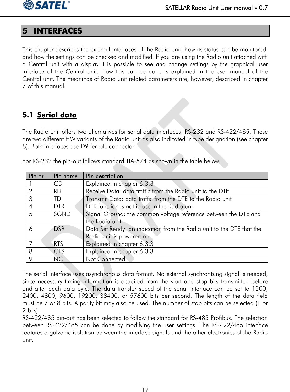
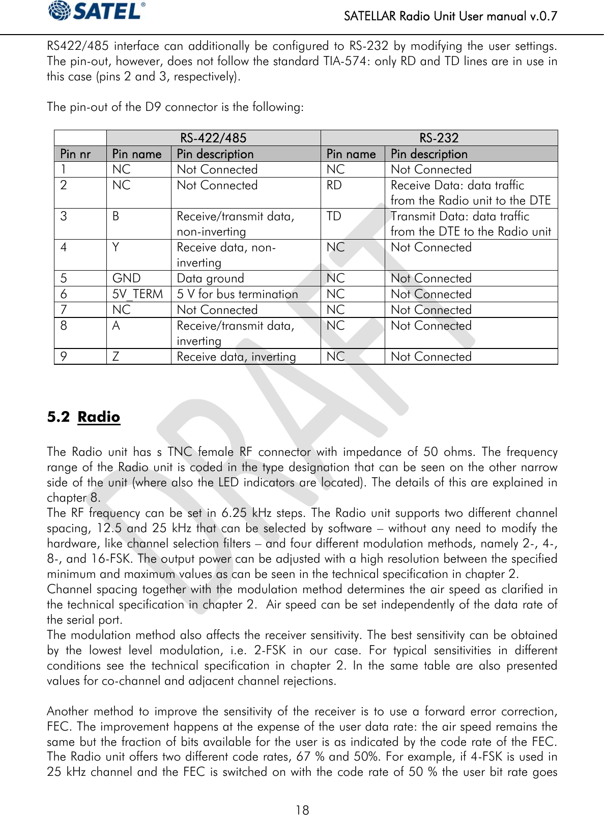
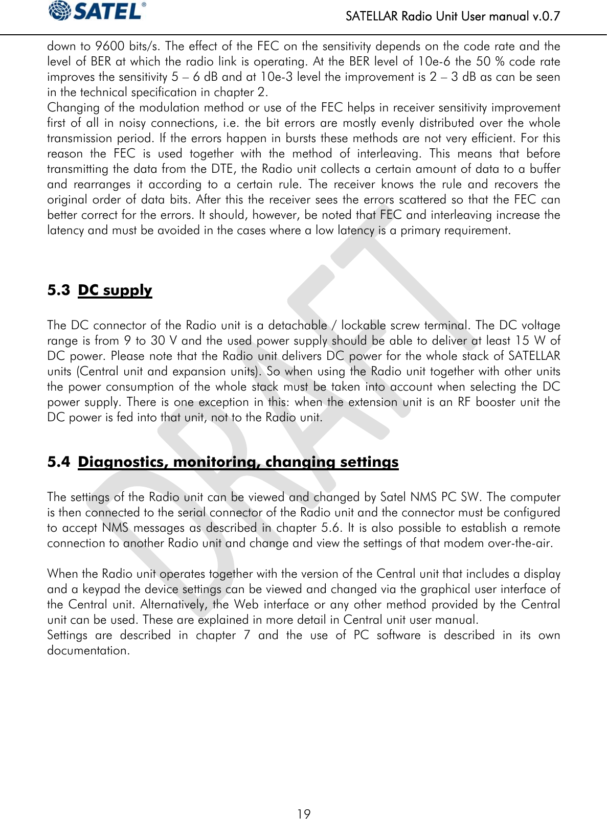
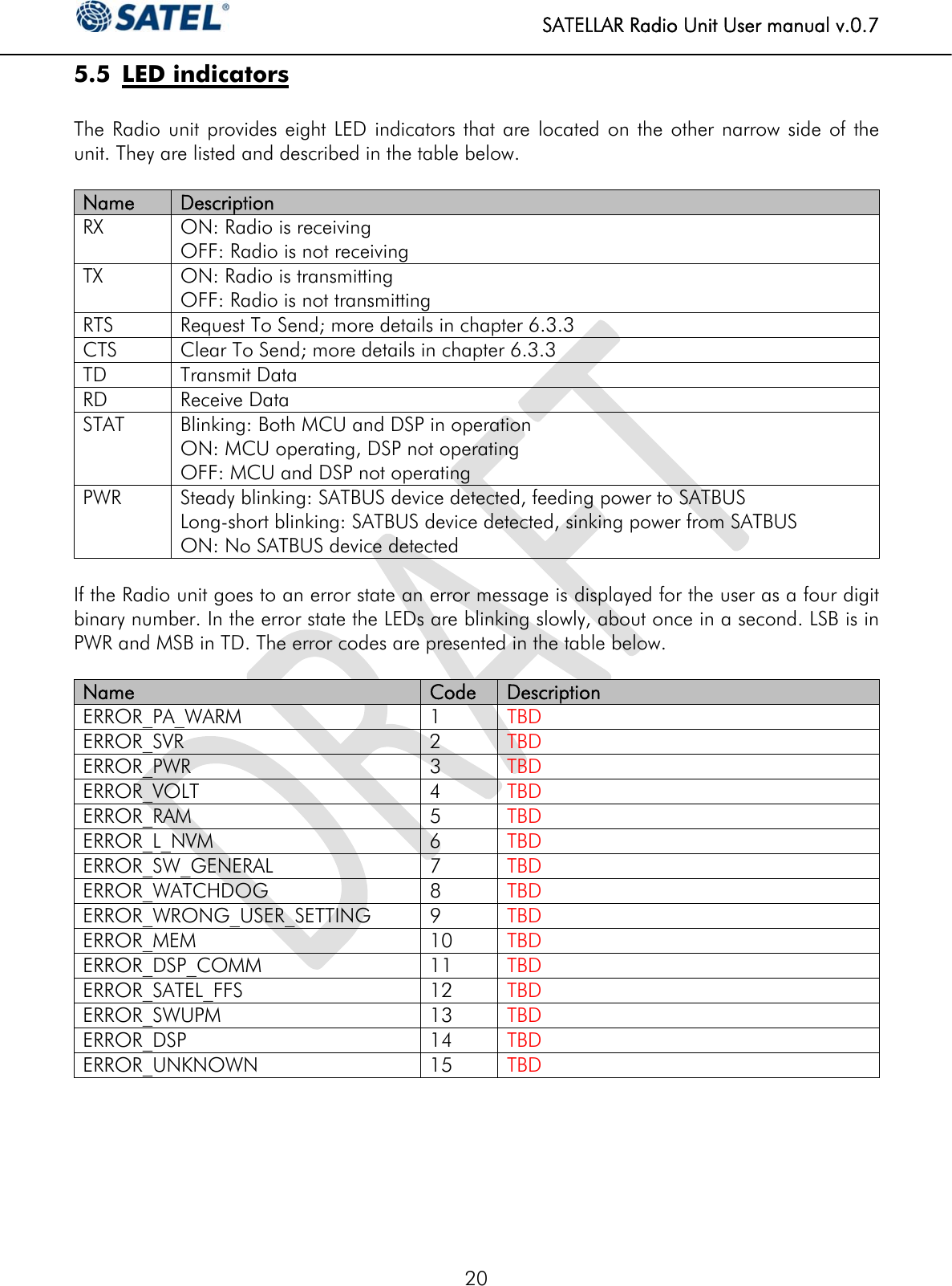
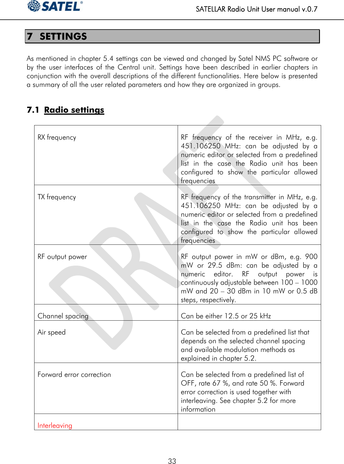
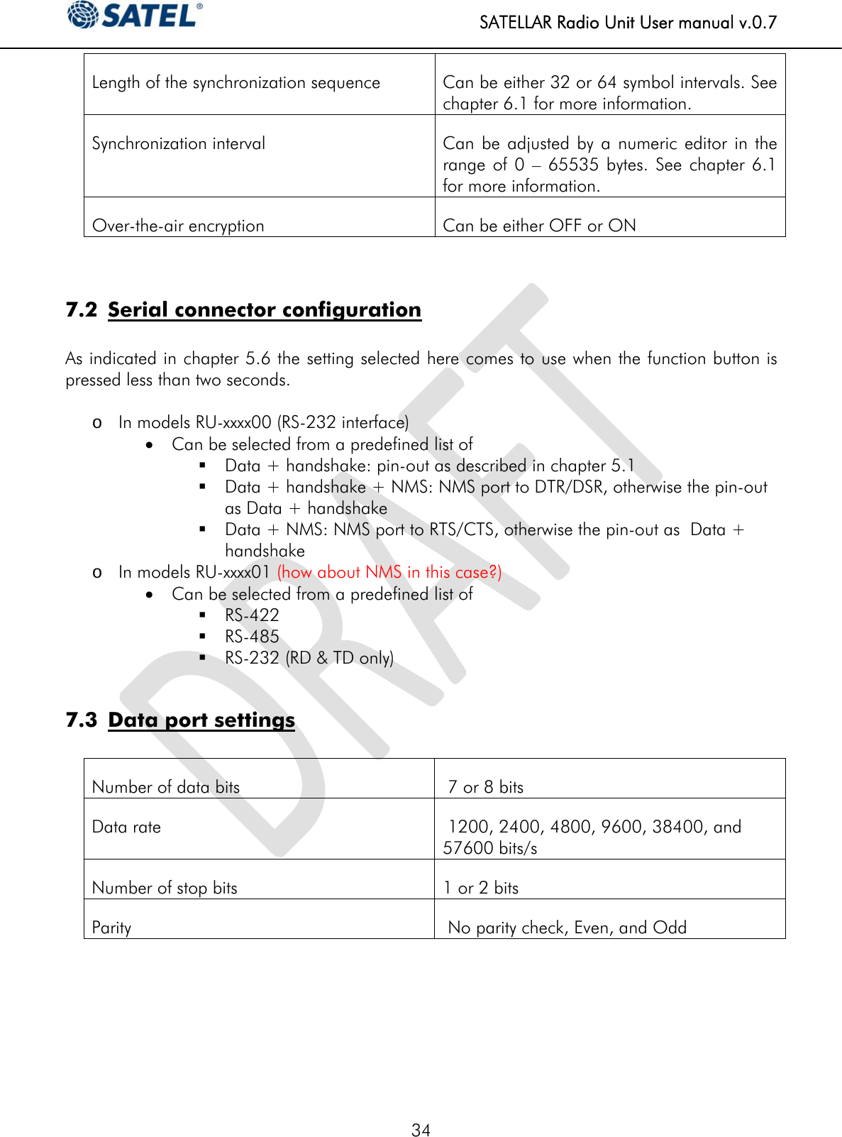
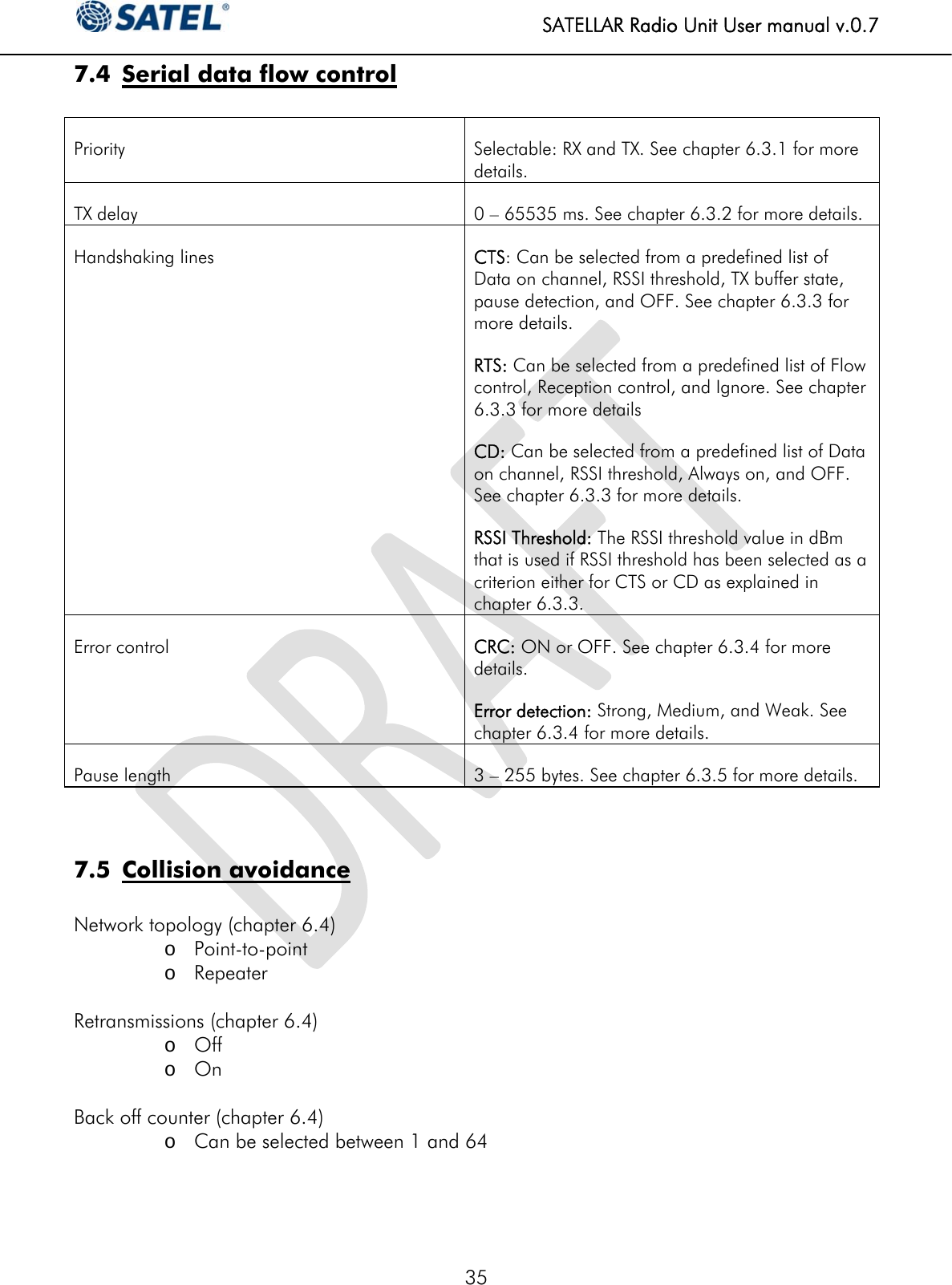
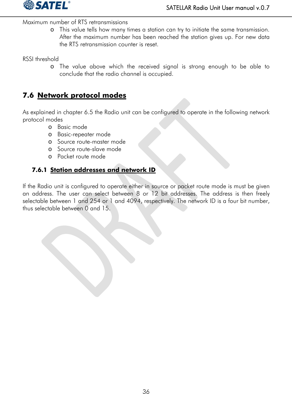
SATEL TA12 User Manual
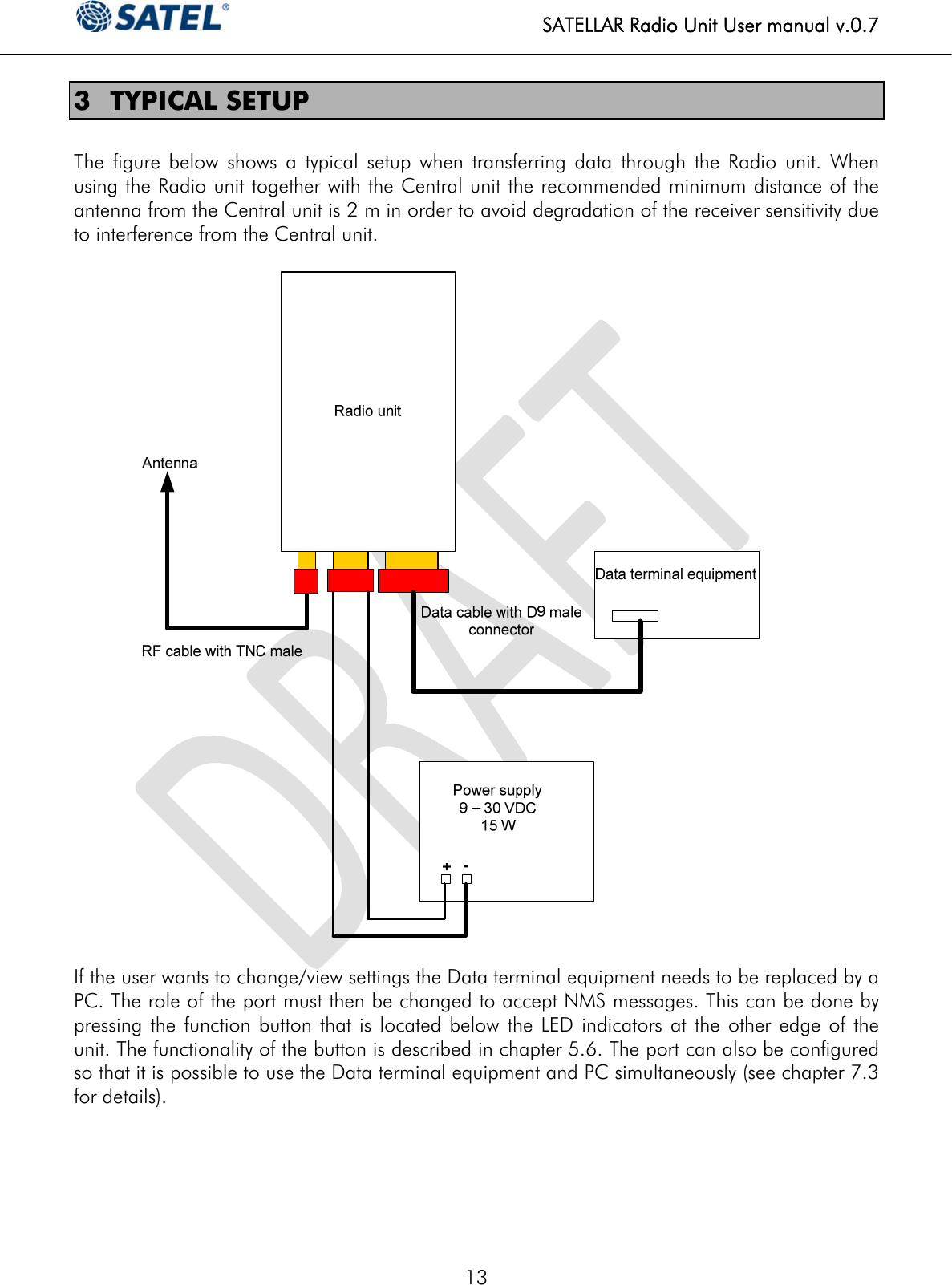
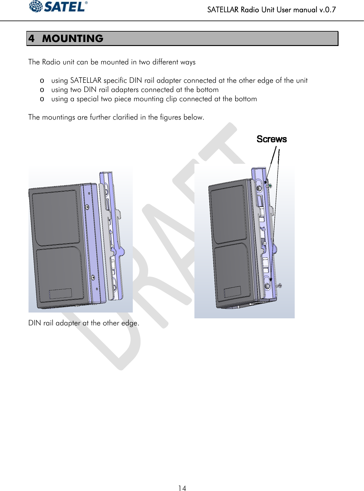
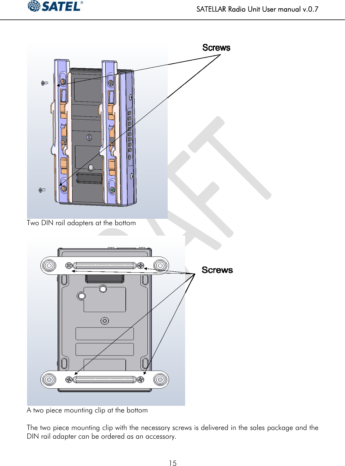
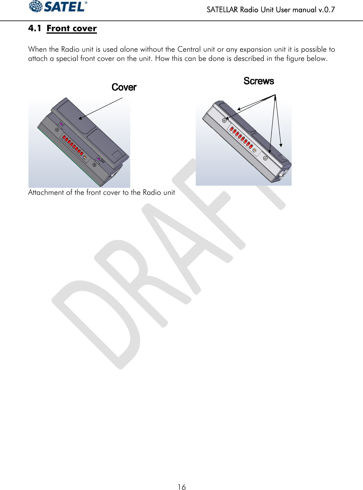
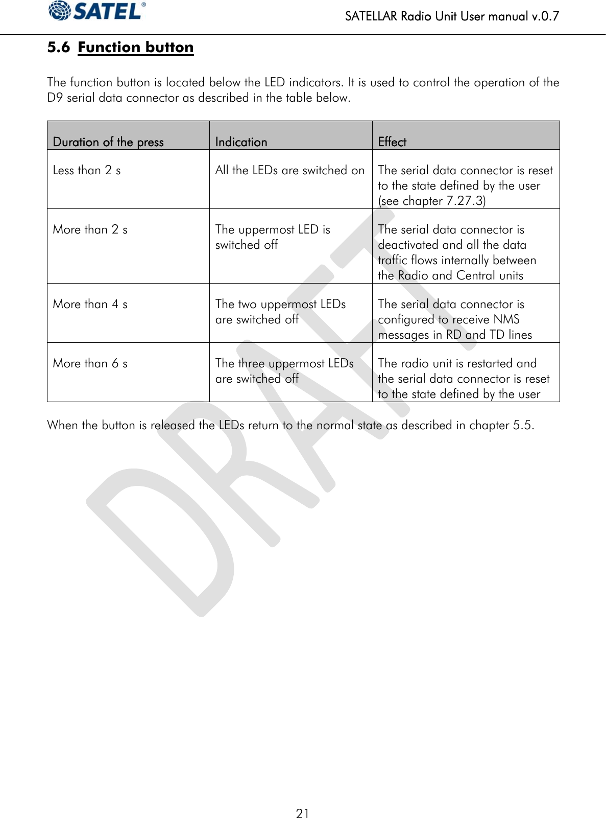
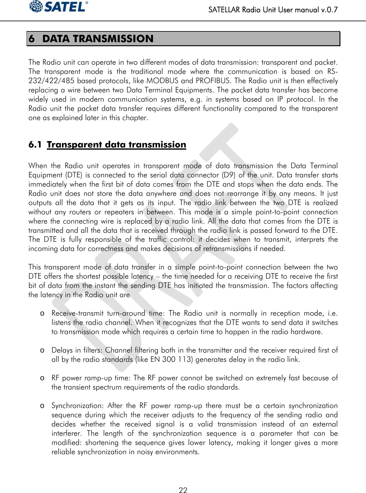
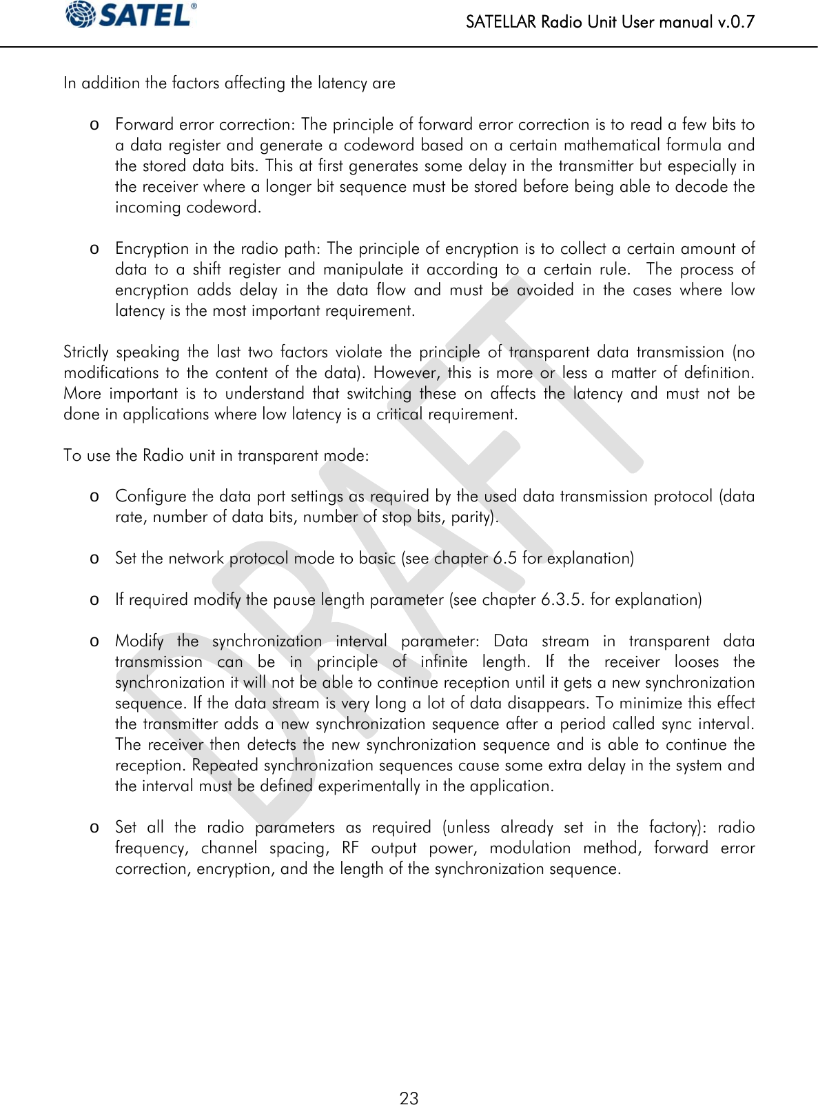
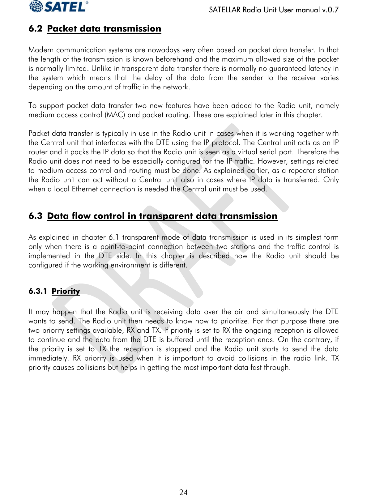
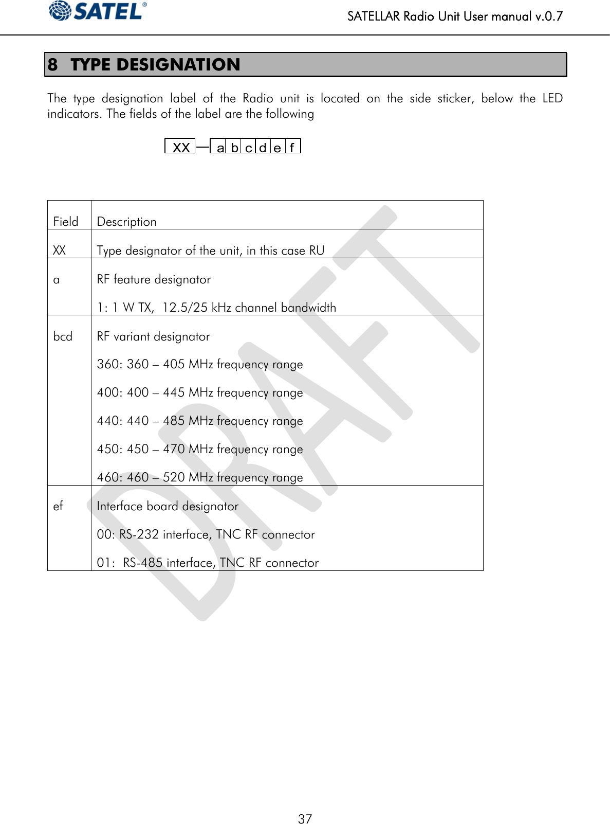
User manual; draft
Navigation menu
Upload a User Manual
Namespaces
Wiki Guide
HTML
PDF
Info
Views
User Manual
Discussion / Help
Navigation