Satel SATEL-TA13 SATELLINE-M3-TR1 User Manual SATELLINE M3 TR1 1 4
Satel Oy SATELLINE-M3-TR1 SATELLINE M3 TR1 1 4
Satel >
User manual of SATEL-TA13
SATELLINE-M3-TR1
User Guide, Version 1.4
1
SATELLINE-M3-TR1
Transceiver Radio Modem
User Guide

SATELLINE-M3-TR1
User Guide, Version 1.4
2
IMPORTANT NOTICE
All rights to this manual are owned solely by SATEL OY (referred to in this user guide as SATEL).
All rights reserved. The copying of this manual (without the written permission from the owner)
by printing, copying, recording or by any other means, or the full or partial translation of the
manual to any other language, including all programming languages, using any electrical,
mechanical, magnetic, optical, manual or other methods or devices is forbidden.
SATEL reserves the right to change the technical specifications or functions of its products, or to
discontinue the manufacture of any of its products or to discontinue the support of any of its
products, without any written announcement and urges its customers to ensure, that the
information at their disposal is valid.
SATEL software and programs are delivered ”as is”. The manufacturer does not grant any kind
of warranty including guarantees on suitability and applicability to a certain application. Under
no circumstances is the manufacturer or the developer of a program responsible for any
possible damages caused by the use of a program. The names of the programs as well as all
copyrights relating to the programs are the sole property of SATEL. Any transfer, licensing to a
third party, leasing, renting, transportation, copying, editing, translating, modifying into another
programming language or reverse engineering for any intent is forbidden without the written
consent of SATEL.
SATEL PRODUCTS HAVE NOT BEEN DESIGNED, INTENDED NOR INSPECTED TO BE USED
IN ANY LIFE SUPPORT RELATED DEVICE OR SYSTEM RELATED FUNCTION NOR AS A PART
OF ANY OTHER CRITICAL SYSTEM AND ARE GRANTED NO FUNCTIONAL WARRANTY IF
THEY ARE USED IN ANY OF THE APPLICATIONS MENTIONED.
Salo, FINLAND 2009
Copyright: 2009 SATEL Oy
No part of this document may be reproduced, transmitted or stored in a retrieval system in any form or by any means without the
prior written permission of SATEL Oy. This document is provided in confidence and must not be distributed to third parties
without the express permission of SATEL Oy.

SATELLINE-M3-TR1
User Guide, Version 1.4
3
RESTRICTIONS ON USE
SATELLINE-M3-TR1 radio modem has been designed to operate on 403...473 MHz, the exact
use of which differs from one region and/or country to another. The user of a radio modem
must take care that the said device is not operated without the permission of the local authorities
on frequencies other than those specifically reserved and intended for use without a specific
permit.
WARNING! Users of SATELLINE-M3-TR1 radio modem in North America should be aware, that
due to the allocation of the frequency band 406.0 – 406.1 MHz for government use only, the
use of radio modem on this frequency band without a proper permit is strictly forbidden.
SATELLINE-M3-TR1
User Guide, Version 1.4
4
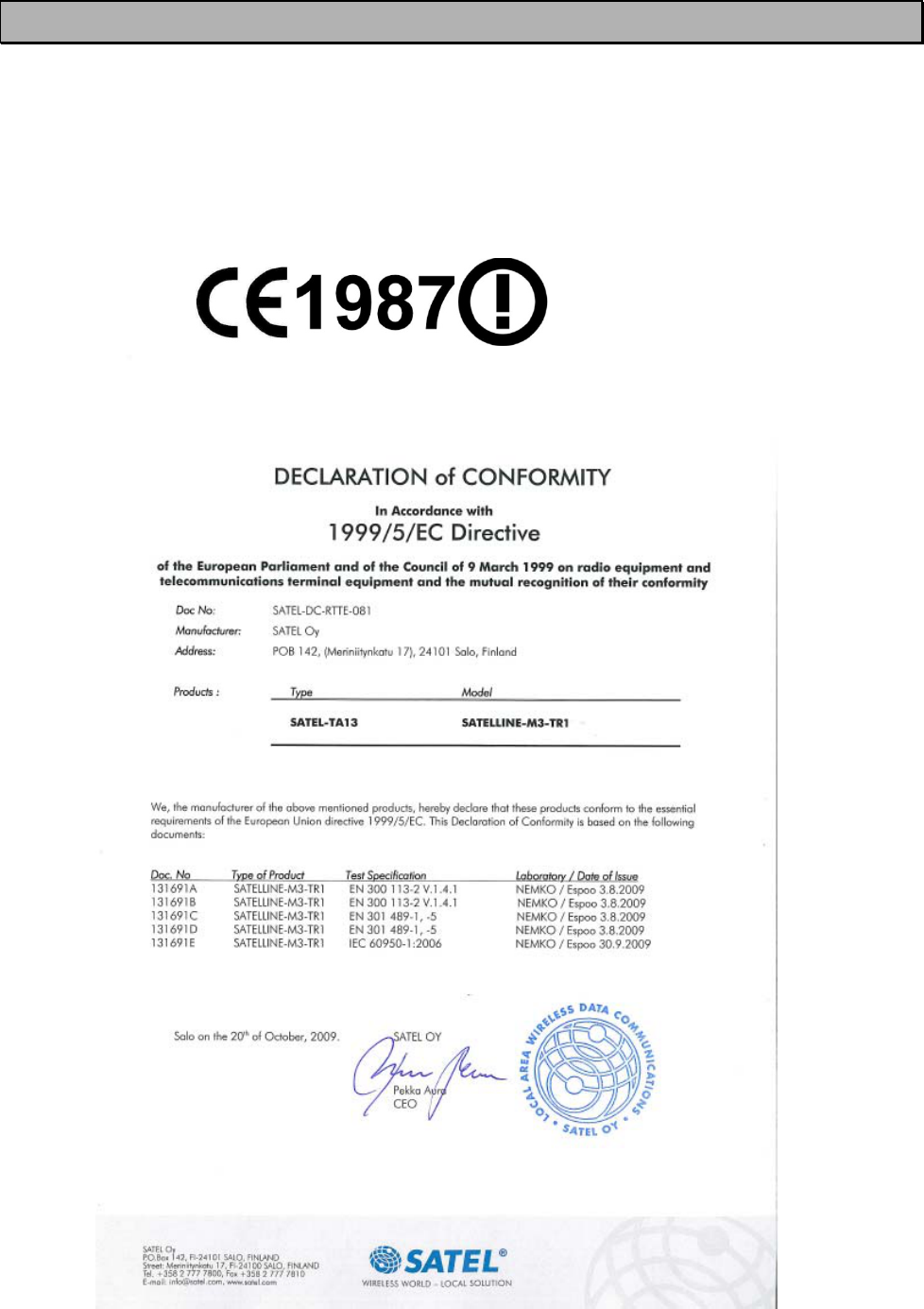
PRODUCT CONFORMITY
SATELLINE-M3-TR1
SATEL Oy hereby declares that SATELLINE-M3-TR1 radio modems are in compliance with the essential
requirements (radio performance, electromagnetic compatibility and electrical safety) and other relevant
provisions of Directive 1999/5/EC. Therefore the equipment is labelled with the following CE-marking.
The notification sign informs users that the operating frequency range of the device is not harmonised
throughout the market area, and the local spectrum authority should be contacted before the usage of
the radio modem is used.

SATELLINE-M3-TR1
User Guide, Version 1.4
5
WARRANTY AND SAFETY INSTRUCTIONS
Read these safety instructions carefully before using the product:
o Warranty will be void, if the product is used in any way that is in contradiction with the
instructions given in this manual, or if the radio modem housing has been opened or
tampered with.
o The radio modem is only to be operated at frequencies allocated by local authorities,
and without exceeding the given maximum allowed output power ratings. SATEL and its
distributors are not responsible, if any products manufactured by it are used in unlawful
ways.
o The devices mentioned in this manual are to be used only according to the instructions
described in this manual. Faultless and safe operation of the devices can be guaranteed
only if the transport, storage, operation and handling of the devices is appropriate. This
also applies to the maintenance of the products.
o To prevent damage it is recommended that both the radio modem and any terminal
devices are switched OFF before connecting or disconnecting the serial connection
cable. It should be ascertained that different devices used have the same ground
potential. Before connecting any power cables the output voltage of the power supply
should be checked.
NOTE!
When selecting a suitable location for the radio modem it must be ensured that no water can
get into the radio modem under any conditions. Direct sunlight is also to be avoided. It is not
recommendable to install the radio modem on a strongly vibrating surface. Suitable
dampening and/or isolation materials should be used in cases where the installation surface
will be subjected to vibration.

SATELLINE-M3-TR1
User Guide, Version 1.4
6
TABLE OF CONTENTS
IMPORTANT NOTICE ............................................................................................. 2
RESTRICTIONS ON USE ......................................................................................... 3
PRODUCT CONFORMITY ........................................................................................ 4
WARRANTY AND SAFETY INSTRUCTIONS ............................................................. 5
TABLE OF CONTENTS ............................................................................................ 6
INTRODUCTION .................................................................................................... 9
1TECHNICAL SPECIFICATIONS ..................................................................... 10
1.1SATELLINE-M3-TR1 Technical Specifications ............................................ 10
2OPERATING VOLTAGE ............................................................................... 12
2.1Operating Voltage (PWR-module) ........................................................... 12
2.2Instructions how to change the PWR module .......................................... 12
2.2.1Fuse ................................................................................................................. 13
2.2.2Power supply ..................................................................................................... 13
3SERIAL INTERFACE ..................................................................................... 14
3.1D-15 connector ......................................................................................... 14
3.2Description of the D-15 connector: .......................................................... 15
3.326-pin PCB connector ............................................................................... 16
3.4RS-485/RS-422 interface .......................................................................... 17
3.4.1RS-485 interface ............................................................................................... 17
3.4.2RS-422 interface ............................................................................................... 18
3.5Termination of RS-422/485 lines ............................................................. 18
4USER INTERFACE ........................................................................................ 19
4.1On-board LED-indicators ......................................................................... 19
4.2Programming Mode ................................................................................. 20
4.2.1Changing the settings ........................................................................................ 20
SATELLINE-M3-TR1
User Guide, Version 1.4
7
5RF INTERFACE ............................................................................................ 22
5.1Transmitter ............................................................................................... 22
5.2Receiver .................................................................................................... 23
5.3Priority RX/TX ........................................................................................... 23
5.4Error correction ........................................................................................ 23
5.5Error checking .......................................................................................... 24
6TRANSPARENT DATA TRANSMISSION ....................................................... 25
6.1Serial interface, data format ................................................................... 25
6.2Handshake lines ...................................................................................... 26
6.2.1CTS-line ........................................................................................................... 26
6.2.2CD-line ............................................................................................................ 26
6.2.3RTS-line ............................................................................................................ 27
6.3Timing and delays during data transmission ......................................... 27
6.3.1Data buffering in the radio modem ..................................................................... 27
6.3.2Pause length ..................................................................................................... 28
6.3.3TX delay ........................................................................................................... 29
6.4Tests
7SETTINGS ................................................................................................... 31
7.1Changing parameters using a terminal device ....................................... 31
7.2Updating Firmware .................................................................................. 32
7.3Basic configuration and installation ........................................................ 32
8SW-RELATED COMMANDS AND OPTIONS ................................................ 34
8.1Repeater mode and addressing .............................................................. 34
8.2Message routing ...................................................................................... 34
8.3Virtual Mode Routing ............................................................................... 34
8.4SL-Commands .......................................................................................... 34
8.4.1Changing parameters using the SL-COMMANDS ................................................. 35
9APPENDIX A .............................................................................................. 36
10APPENDIX B .............................................................................................. 37
SATELLINE-M3-TR1
User Guide, Version 1.4
8
10.1Functional delays ..................................................................................... 37
10.2Transmission related delays .................................................................... 37
10.2.1Transmission delays when using a 12.5 kHz radio channel .................................... 38
10.2.2Transmission delays using a 25 kHz radio channel ............................................... 40

SATELLINE-M3-TR1
User Guide, Version 1.4
9
INTRODUCTION
SATEL OY is a Finnish electronics and Telecommunications Company specialising in the design
and manufacture of wireless data communication products. SATEL designs, manufactures and
sells radio modems intended for use in applications ranging from data transfer to alarm relay
systems. End users of SATEL products include both public organisations and private individuals.
SATEL is the leading European manufacturer of radio modems. SATEL radio modems have been
certified in most European countries and also in many non-European countries.

SATELLINE-M3-TR1
User Guide, Version 1.4
10
1 TECHNICAL SPECIFICATIONS
1.1 SATELLINE-M3-TR1 Technical Specifications
SATELLINE-M3-TR1 complies with the following international standards:
• EN 300 113-2
• EN 301 489 (EMC-requirements)
• EN 60950 (Safety Standard)
RECEIVER TRANSMITTER Note!
Frequency Range 403...473 MHz
Channel Spacing 12.5 kHz / 20 kHz / 25 kHz programmable
Tuning range 70 MHz
Spurious Radiations < 2 nW EN 300 113 and CRF47 part90
Frequency error tolerance < 1 kHz
Sensitivity
- 114... -111 dBm
(BER < 10 E-3)
FEC On.
See:Note 1
Co-channel Rejection
< 15 dB FEC On
Adjacent Channel
Selectivity > 45 / 50 dB FEC On
Intermodulation
Attenuation >45 dB FEC ON
Blocking >86 dB FEC ON
Spurious Rejection 60 dB FEC On
Spurious Emission <-57 / -47 dBm
< -70 dBm on
3rd harmonics.
Others <
-120 dBm
Power Consumption <1.2 W
<3 W @ 0.5W output power
<7 W @ 1W output power
Power Consumption,
Sleep ON 0.24 W typical
Communication Mode Half-Duplex
Type of Emission F1D
Carrier power 100, 200, 500, 1000 mW
Adjacent Channel Power
EN 300 113 and CRF47 part90
Carrier power stability < ±1.5 dB
DATA MODEM
Timing RS-232
Electrical Interface RS-232 & LVTTL or RS-232 & TTL
Order
options
Interface Connector D-15 (female) as standard, others by request.
Data speed of
I/O-interface 300 – 38400 bps
Data speed of Radio
Interface
19200 bps (25 kHz channel) /
9600 bps (12.5 kHz channel)
Data Formats Asynchronous data
Modulation 4FSK, GMSK (PCC, TrimTalk)
SATELLINE-M3-TR1
User Guide, Version 1.4
11
GENERAL
Operating Voltage
Nominal: 3-9V and 6-30V
3.2-8.5V or 6.5-28Vdc +/-10%.
Two Voltage
level options
Maximum Operating
Temperature Range
-30
°C ... +65 °C
Operational
Normal Operating
Temperature Range
-25 °C ... +55 °C
A
ll
specifications
met
Storage Temperature -40 °C ... +80 °C
Antenna Connector 50 ohm, U.FL
Construction PCB with sheet metal EMI shields
Size L x W x T 96 mm x 56 mm x 9 mm
Weight 50 g
OTHER MEASURES
ESD-failure threshold 8 kV contact, 15 kV air discharge
Note 1
Due to radio electronic design, the receiver is about 3-5dB less sensitive on the following 6 frequencies:
403.000MHz, 416.000MHz, 429.000MHz, 442.000MHz, 455.000MHz, 468.000MHz.
SATELLINE-M3-TR1
User Guide, Version 1.4
12
2 Operating Voltage
2.1 Operating Voltage (PWR-module)
The SATELLINE-3AS-TR1 radio modem can have two (2) operating voltage ranges. The range is
set at the factory. The voltage level must be mentioned in the order. The operating voltage
range is changed by replacing the PWR-module.
The operating voltages are: 3.2-8.5 VDC or 6.5V - 28 VDC +/-10%.
The nominal voltages are 3-9V and 6-30V. The radio modem must only be connected to a
power supply with an adequate current output. The Input Voltage range is marked in the label.
The lower voltage PWR- module PCB is marked as SPL0006x and the higher voltage module is
SPL0010x.
Note 2
Do not exceed the operating voltages range. Exceeding of the operating voltage may damage
the module.
Note1
The modem withstands a live insertion or removal from the DTE-unit without switching OFF the
power.
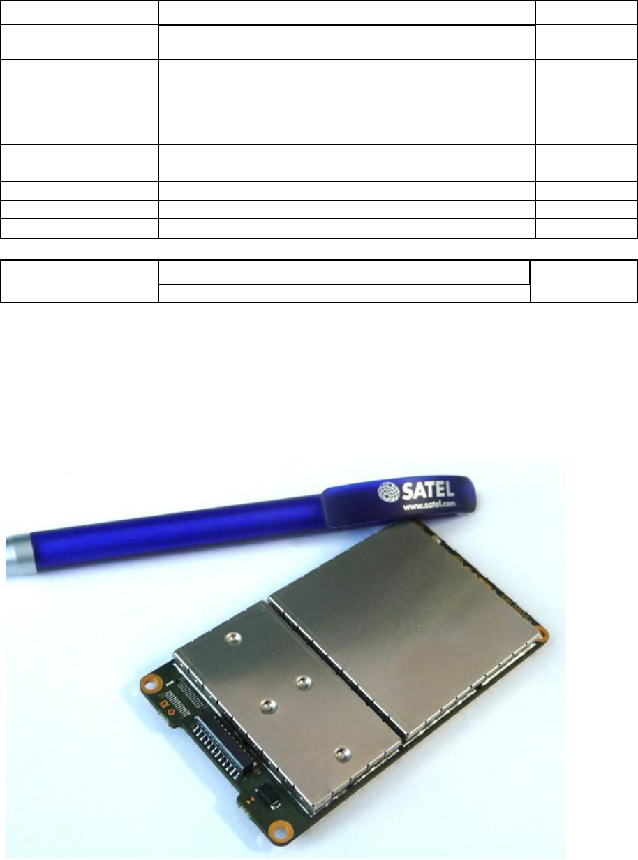
2.2 Instructions how to change the PWR module
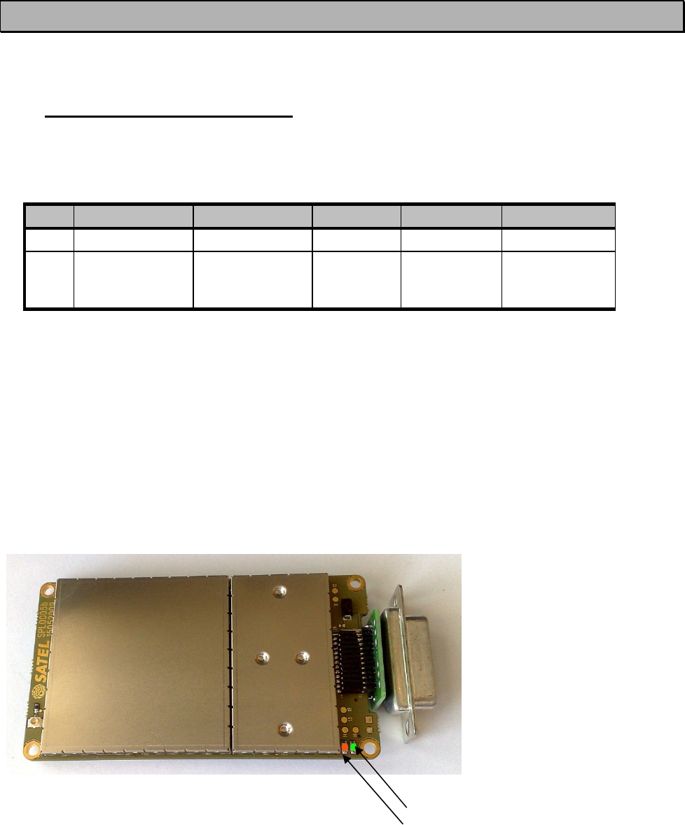
The radio module includes a removable PWR module, which can be changed if needed.
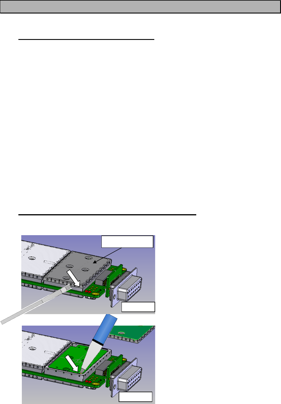
Picture1
Use a small screw driver and move the
sheet metal nails up one-by-one until
it removes.
Picture2
Open the PWR module by setting a
pen into the whole of the corner and
bend as long as the module turns out.
Picture 2
PWR-module
Picture 1
SATELLINE-M3-TR1
User Guide, Version 1.4
13
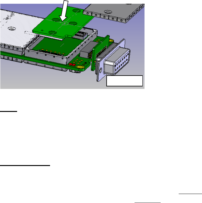
Picture3
Press the new PWR module back in
reverse order.
2.2.1 Fuse
A proper fuse must be connected in between the radio modem and the power supply. The
correct value depends on the model (see list below). Recommended value is 2A slow.
2.2.2 Power supply
The radio modem must only be connected to a power supply with an adequate current output.
The pins 15 and 14 of the D-connector are connected to the positive power supply line. The
pins 8 and 7 of the D-connector are connected to negative power supply line (ground).
The DTR-line of the radio modem, which is connected to pin 1, can be used as an
ON/STANDBY –switch, and in this way the radio modem can be switched either ON
(operational state) or OFF (STANDBY). The logical state "1" (Open or more than +3.0 V, max
Vdc) of the DTR-line corresponds to ON-state and a logical state "0" (.. <=0 V) corresponds to
a STANDBY state.
In applications, where the radio modem is used as a portable device (meaning battery
operation), the DTR-line (pin 1) should be connected to a logical state "0" always when it is
possible to conserve battery power and prolong operational time between battery charging.
NOTE! There is a galvanic connection between signal ground (SGND, pin 7), ground (GND,
pin 8), outer conductor of antenna connector and modem casing.
Picture 3
SATELLINE-M3-TR1
User Guide, Version 1.4
14
3 SERIAL INTERFACE
The radio modem is referred to as DCE (Data Communication Equipment) whereas the PC or
equivalent device is referred to as DTE (Data Terminal Equipment). The SATELLINE-M3-TR1
radio modem include a 15-pin ‘D’-type female connector, which contains all the connections
required to establish communication between the radio modem, acting as the DCE, and the PC,
acting as the DTE.
The radio modem contains two (2) serial ports, which are designated as Port 1 or Port 2 for
communication. Only one port at a time can be used for communication. The Interface must be
specified in the order. The Port 1 is always RS-232, but the Port 2 can be set to LVTTL, TTL, RS-
232 or RS422.
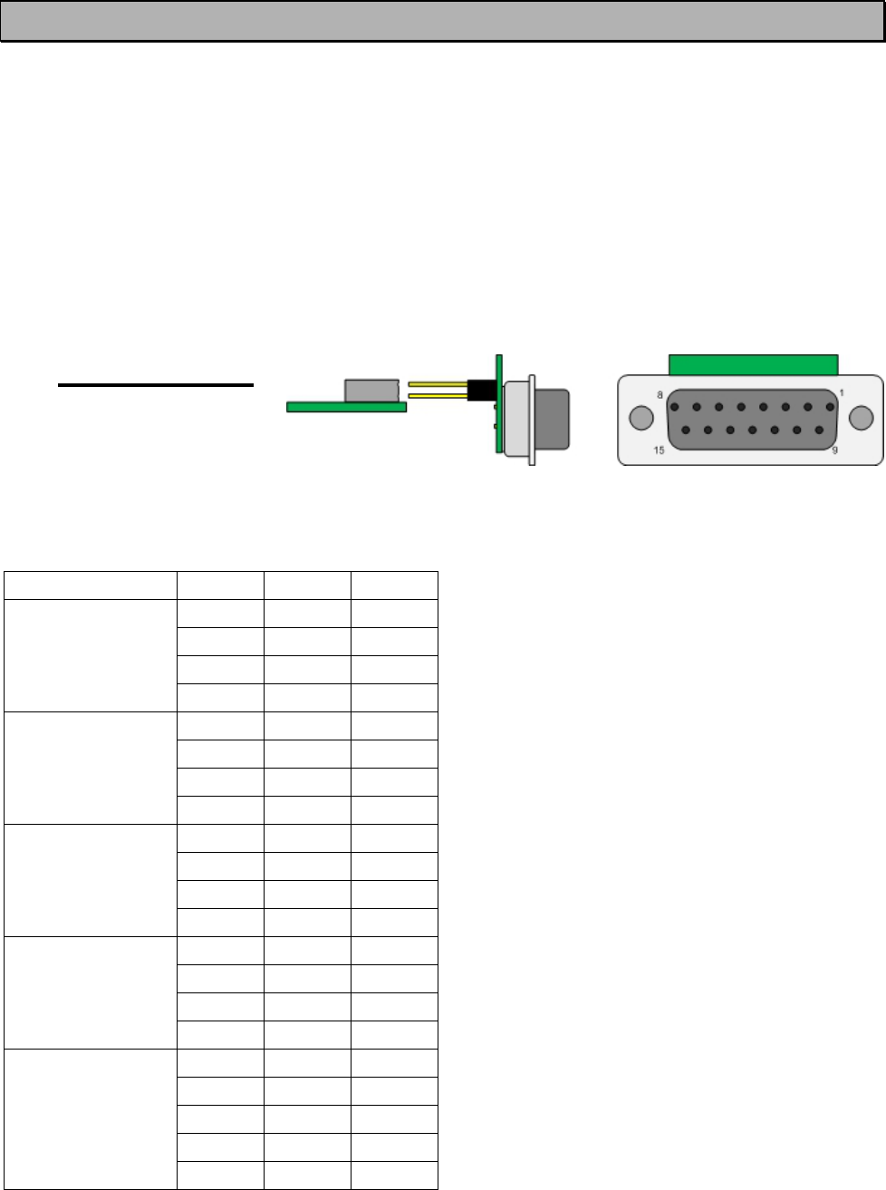
3.1 D-15 connector
D-15 female connector adapter of the radio modem
Pinout of the D-15
PORT PIN DIR SIGNAL
PORT 1 RS-232
6 OUT CTS
9 OUT RD1
11 IN TD1
13 IN RTS
PORT 2 TTL/LVTTL
2 OUT CTS
3 OUT RD
4 IN TD
5 IN RTS
PORT 2 RS-232
2 OUT CD
3 OUT RD2
4 IN TD2
5 - NC
PORT 2 RS-422
2 OUT A'
3 OUT B'
4 IN A'
5 IN B'
COMMON
1 IN DTR
10 OUT DSR
12 IN MODE
7,8 - GND
14,15 - VB

SATELLINE-M3-TR1
User Guide, Version 1.4
15
o DTE is an abbreviation for Data Terminal Equipment
o DIR column below denotes the direction of the signal:
"IN" is from DTE to the radio modem, "OUT" is from the radio modem to the DTE.
Port 1 complies always with the RS-232 standard.
Port 2 can comply either with the RS-232, LVTTL, TTL or RS-422 standards. The interface type is
set at the factory according to the customer order. The user can set the Ports ON/FF afterwards
in the programming mode.
NOTE! Unused pins can be left unconnected.
*) RTS and CTS handshaking connections remain the same irrespective of the port used (Port 1 or Port 2).
**) A and B designators are opposite in Profibus standard.
3.2 Description of the D-15 connector:
• DTR. Data Terminal Ready.
When open or connected to + Voltage the unit is ready for normal transfer mode.
When connected to Ground the unit goes to low current consumption mode.
OFF = <=0V, ON = >= 3V-30V.
• CTS. Clear To Send.
• RD. Receive data.
Asynchronous serial data.
• TD. Transmit data.
Asynchronous serial data.
• RTS. Request to Send.
• CTS. Clear To Send.
• GND. Ground
Both the negative pole of the operating voltage and the signal ground.
• MODE.
Programming pin. When floating or connected to +VDC the unit is in normal mode. When
connected to Ground the unit is in programming mode.
NOTE!
When the MODE-Pin (Pin 12 of the D-Connector) is connected to Ground, the modem is
in the Programming Mode and Port 1 (PINS 6, 9, 11,13) will be in use! If you normally
use Port 2 for data transmission, the serial cable must be changed to a suitable type when
switching over to the configuration mode.
SATELLINE-M3-TR1
User Guide, Version 1.4
16
MODE = operational mode. When the MODE-line is connected to ground (GND), the radio
modem enters the Programming Mode which is used to change the settings of the radio modem
(i.e. configuration, set-up). If the MODE-line is not connected, the radio modem will enter the
Data Transfer Mode, in which data can be transmitted and received. The Programming Mode is
used only when installing a radio modem and changing the operational parameters of a
network. Normally the radio modem is always in the Data Transfer Mode.
• RTS, Request To Send
• PWR
+VDC. Vb Positive pole of the operating voltage.
NOTE!
• Port 1 or 2 can be defined using the Configuration Manager. When the Program switch of
the adapter is switched ON (Programming-mode) the default Port is always Port 1, 9600, N8,
1. When the Port has been defined, it’ll be activated by switching the Power OFF-ON, or
switching the Program Switch switched to OFF.
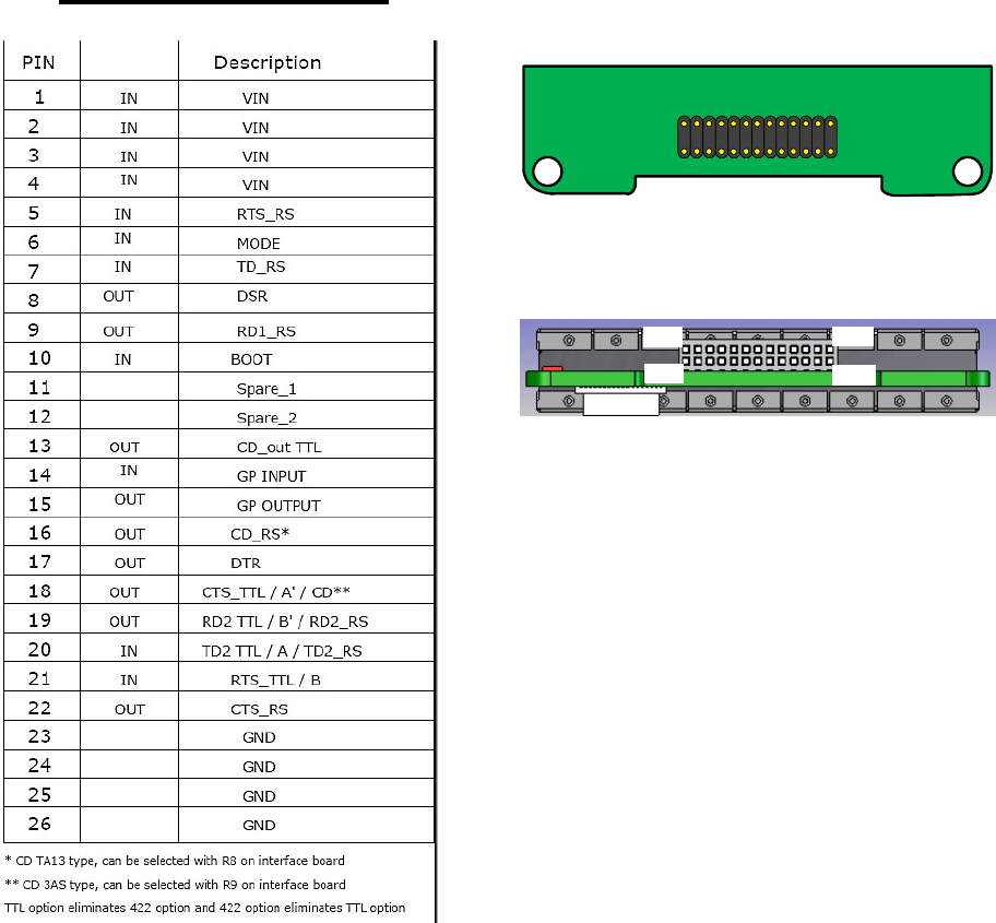
3.3 26-pin PCB connector
Vertical strip, male.
Horizontal header, female.
1
2614
13
1
13
14 26
SATELLINE-M3-TR1
User Guide, Version 1.4
17
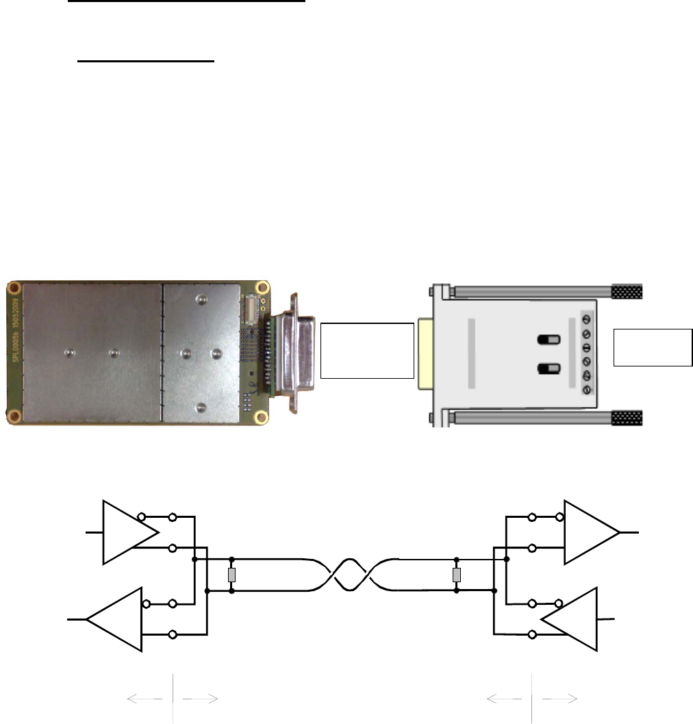
3.4 RS-485/RS-422 interface
3.4.1 RS-485 interface
RS-485 is an extension of the RS-422 standard and enables the connection of more than two
devices on to the same bus. Communication is half-duplex, so there is only one cable pair,
compared to two when using the RS-422. The RS-485 standard defines the electrical
characteristics of the connections in such a way as to prevent possible data contention states as
well as cable shorts etc. from harming the devices themselves. To enable RS_485 function set
the modem must be ordered with RS-422 Interface. When RS-485 is used the RS-422 on Port 1
must be ON.
TR1 NARS-2-4A
R
T
120
Ω
Radio modem Cable
Terminal
Cable
R
T
120
Ω
R
T
B
A
B
'
A
'
T
R
B'
A'
B
A
Port 2
=RS-422 RS-485
SATELLINE-M3-TR1
User Guide, Version 1.4
18
3.4.2 RS-422 interface
RS-422 standard defines a serial data transfer method, which is very similar to the RS-232
standard. In RS-422 however, the signal lines are balanced (or differential) transmission lines. A
balanced (or differential) transmission line is formed by using two signal wires together to convey
each single signal. Because the state of the signal is defined by the mutual voltage difference
(hence the name differential), any common mode disturbances induced into the lines will cancel
out. The effect of different signals moving in the same cable will also be smaller than in the case
of the RS-232. Transmission distance can be considerably longer than when using RS-232 type
of connection, and distances of 1 km are possible.
As an example, let’s examine the TX-signal: TX-signal will be transmitted using two lines (A and
B). A logical ”1” corresponds to a situation, where the voltage on line A is greater than the
voltage on line B. Correspondingly a logical ”0” corresponds to a situation, where the voltage
on line A is smaller than the voltage on line B.
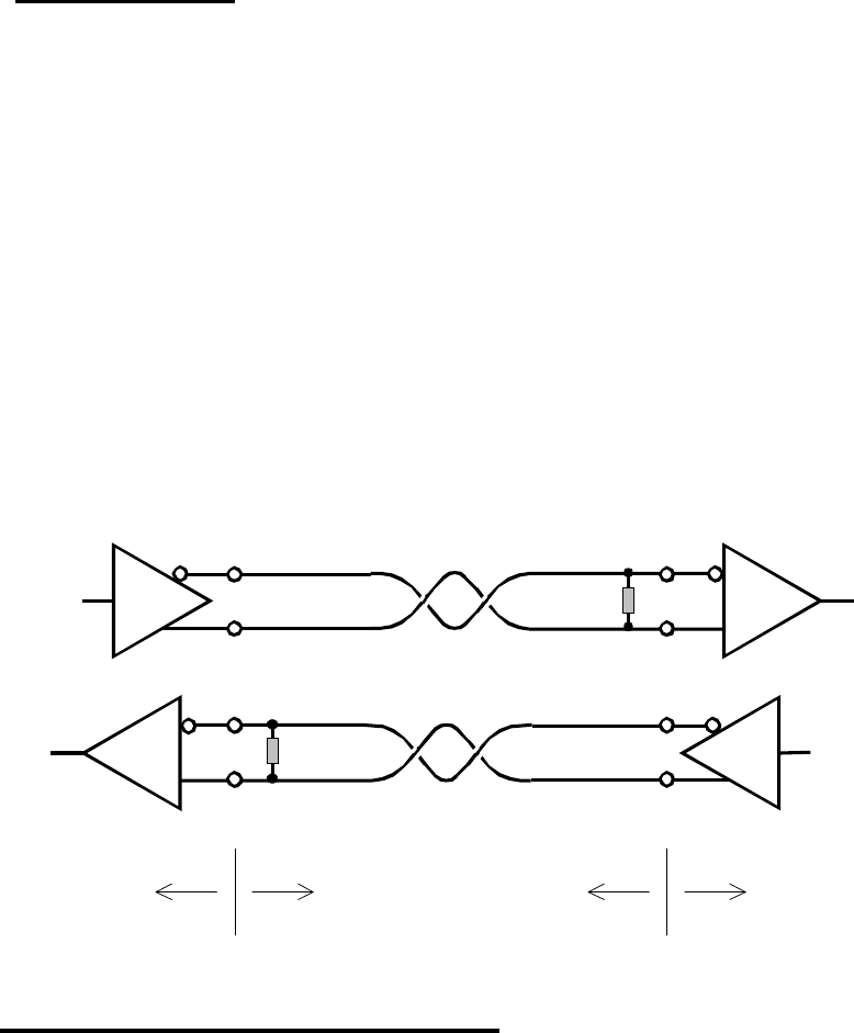
3.5 Termination of RS-422/485 lines
Each differential pair of wires is a transmission line. A transmission line must be terminated
properly to prevent, or at least minimise, harmful reflections formed between the transmitting
and receiving end of the transmission line. A common method of terminating a RS-485 type of
transmission line is to connect a so-called termination resistor, between the wires and at both
ends of the transmission line. Even when there are more than two devices on the same
transmission line, the termination resistors are needed only at the ends of the transmission line.
The termination resistor must be selected so that its resistance matches the characteristic
impedance of the transmission line as close as possible (typical values range from 100 to 120
Ω). When using a RS-422 type of connection the termination resistor is connected only at each
of the receiving ends. Termination resistors are particularly important when using long
transmission lines and/or high data transfer speeds.
R
T 120 Ω
RT
RT 120 ΩR
T
BB'
AA'
B' B
A' A
Radio modem Cable Terminal
Cable
SATELLINE-M3-TR1
User Guide, Version 1.4
19
4 USER INTERFACE
4.1 On-board LED-indicators
There are two (2) LED-indicators on the PCB of the radio modem, and they give an indication of
the status of the serial port and the radio interface:
LED Colour Indication OFF, SLEEP
ON
Red, Flashing
Power Green ON/OFF Inactive
Active
RX/TX Red Data indicator,
Programming
Mode
No data
transferred
Programming
mode
Data transfer
Description of the LED-indicators:
• Power indicates the status of Power ON/OFF
• RX/TX indicates that the radio modem is receiving or transmitting data via serial port
• Mode indicates whether the modem on Data- or Programming mode
• Power ON/OFF. ON=Green.
• DATA on line (RX/TX)= Red Flashing

SATELLINE-M3-TR1
User Guide, Version 1.4
20
4.2 Programming Mode
The settings of SATELLINE-3AS-TR1 are fully configurable in Programming Mode by using a
suitable terminal program. The most recommendable set-up (optional): NARS-1F interface
adapter, CRS-9 cable, a power supply and the SaTerm terminal program. NARS-1F contains a
switch to enable easy shifting into the Programming Mode. Other suitable terminal programs like
SATEL Configuration Manager may also be used.
The radio modem will shift into the Programming Mode by connecting the D-connector pin 12 to
ground (GND). When using the NARS-1F this can be accomplished by moving the slide switch
downwards.
In the Programming Mode, the radio modem will use serial port PORT1, with settings 9600 bps,
N, 8,1 (data transfer speed 9600 bps, no parity, 8 data bits and 1 stop bit). For more detailed
instructions for changing each setting.
4.2.1 Changing the settings
o Connect cables (RS-232 cable to PC COM-port, power supply cable to power supply).
o Switch on the PC and start SaTerm program (or other terminal program).
o Open a terminal window and then choose ”Pr” (in case you are using some other
terminal program, set the serial port parameters of the program as follows: 9600 bits/s,
8 data bits, no parity, 1 stop bit, which is always the default in Programming Mode).
o Connect PROG-pin to ground (if using the NARS-1F adapter, slide the switch
downwards), the radio modem shifts now into the Programming Mode. The screen should
look similar to the one shown in the picture below.
o Make desired changes to the settings.
o Save changes by pressing ”E” in the main menu. If you don’t want to save changes, press
”Q”.
o Disconnect PROG-pin from ground (if using the NARS-1F adapter, slide the switch
upwards), the radio modem should now return to the Data Transfer Mode.
***** SATELLINE-3AS M3-TR1 *****
SW:06.16.3.34 / HW: SPL0005B / PV: 00.00 / IM: 02 /
--------------------------------------------------------------------------------
Current settings
----------------
1) Radio frequency 436.5000 MHz ( CF 436.5000 MHz, spacing 25 kHz )
2) Radio settings Tx power level 1000 mW / Signal threshold -112 dBm / FCS OFF /
TX start delay 0 ms / Diversity RX OFF / EPIC PWRSave OFF /
Compatibility Satel 3AS
3) Addressing RX address OFF / TX address OFF /
RX address to RS port OFF / TX address autoswitch OFF

SATELLINE-M3-TR1
User Guide, Version 1.4
21
4) Serial port 1 ON / 19200 bit/s / 8 bit data / None parity / 1 stop bit
5) Serial port 2 OFF / 19200 bit/s / 8 bit data / None parity / 1 stop bit (RS-232)
6) Handshaking CTS Clear to send / CD RSSI-threshold /
RTS Ignored / Pause length 3 bytes
7) Additional setup Error correction OFF / Error check OFF / Repeater OFF /
SL-commands ON / Priority TX / Full CRC16 check OFF
8) Routing OFF
9) Tests OFF
A) Restore factory settings
E) EXIT and save settings
Q) QUIT without saving
Enter selection >
More information at Satel.com
SATELLINE-M3-TR1
User Guide, Version 1.4
22
5 RF INTERFACE
The SATELLINE-M3-TR1 module has a single antenna connector with an impedance of 50 ohm.
The user can change the frequency of the radio modem afterwards within the frequency range.
The data speed of the radio interface depends on the chosen radio channel spacing. A channel
spacing of 25 kHz enables a data speed of 19200 bps and a channel spacing of 12.5 kHz and
20 kHz enables, correspondingly, a data speed of 9600 bps. The data speed of the radio
interface is always fixed (19200 bps or 9600 bps), irrespective of the data speed of the serial
interface. If the data speeds of the radio interface and the serial interface differ from each other,
the radio modem will temporarily buffer the data in transfer, so no data loss will occur.
5.1 Transmitter
The output power of the transmitter is adjustable between 100, 200, 500 or 1000 mW. The
greatest allowable power depends on limits set by local authorities, which should not be
exceeded under any circumstances. The output power of the transmitter should be set to the
smallest possible level which still ensures error free connections under variable conditions. Large
output power levels using short connection distances can, in the worst case, cause disturbances
to the overall operation of the system.
OUTPUT POWER
dBm
100 mW
+20
200 mW
+23
500 mW
+27
1 W
+30
Possible output power settings
NOTE!
Setting the radio data modem output power level to that which exceeds the regulations set
forth by local authorities is strictly forbidden. The setting and/or using of non-approved
power levels may lead to prosecution. SATEL and its distributors are not responsible for any
illegal use of its radio equipment, and are not responsible in any way of any claims or
penalties arising from the operation of its radio equipment in ways contradictory to local
regulations and/or requirements and/or laws.

SATELLINE-M3-TR1
User Guide, Version 1.4
23
5.2 Receiver
The sensitivity of the receiver depends on the channel spacing of the radio modem (=data
speed of the radio interface) and on the mode of the FEC (error correction) according to the
table below:
FEC OFF FEC ON
25 kHz -110 dBm -113 dBm
20 kHz -112 dBm -115 dBm
12.5 kHz -112 dBm -115 dBm
The Signal Threshold Level setting of the receiver determines a level above which the search for
the actual data transfer signal is active. If the Signal Threshold Level setting is set too low, it is
possible that the receiver is trying to synchronise itself with noise, in which case, the actual data
transmission might remain unnoticed. Alternatively, weak data transmissions will be rejected,
even though they would be otherwise acceptable.
5.3 Priority RX/TX
SATELLINE-3AS-TR1_xx offers a Priority setting, which selects the priority between reception and
transmission. The setting can be changed in Programming Mode. By default, transmission has
higher priority than reception i.e. the default value is Priority TX.
Priority TX means that a terminal device attached to a radio modem decides the timing of the
transmission. The transmitter is immediately switched on when the terminal device starts to
output data. Should reception be in progress, the radio modem will stop it and change to a
transmit state. There is no need to use any handshaking for the control of timing.
Priority RX means, that a radio modem tries to receive all data currently in the air. If a terminal
outputs data to be transmitted (or an SL command) it will buffered. The radio modem will wait
until the reception has stopped before transmitting the buffered data. This will result in timing
slacks to the system, but decreases the number of collisions on the air; this is particularly useful
in systems based on multiple random accesses.
If the Repeater Function has been set on, priority setting is automatically switched to RX mode.
5.4 Error correction
FEC, Forward Error Correction. FEC-function is switched ON (or OFF) by using the
Programming Mode. When activated, the FEC-function will automatically add additional error
correction information, which increases the amount of transmitted data by 30 %. It is used by the
receiving radio modem to correct erroneous bits - as long as the ratio of correct and erroneous
bits is reasonable.
Error correction improves the reliability of data transfer via the radio interface especially in
unfavourable conditions. FEC-function should be used when link distances are long and/or if

SATELLINE-M3-TR1
User Guide, Version 1.4
24
there are many disturbances in the radio channels used. The use of the FEC-function will,
however decrease the data transfer throughput of data by about 30 %. For a listing of exact
delays introduced by using FEC-function.
To switch the FEC-function ON in the Programming Mode, select:
1) Error correction ON
5.5 Error checking
When the error checking is switched on, the radio modem will add a checksum to the
transmitted data. When the data is received, the checksums are verified before data is forwarded
to the serial port. There are two different options for error checking that can be accessed in the
Additional setup menu in the Programming Mode:
2) Error check
6) Full CRC16 check
Error check checks data partially while data is received.
Full CRC16 check function adds two checksum characters at the end of the user data message.
At the reception end the receiver receives first the whole package and if the checksum matches
the data message is forwarded to the serial port. If Full CRC16 check is selected it must be set
ON for all radio modems in the same network. Otherwise the checksum characters appear at
the end of user message on the serial port.
NOTE!
All radio modems, which are to communicate with each other, must have the same setting
for FEC (ON or OFF). If the transmitting radio modem and the receiving radio modem has
different settings, data will not be received correctly.
SATELLINE-M3-TR1
User Guide, Version 1.4
25
6 TRANSPARENT DATA TRANSMISSION
6.1 Serial interface, data format
The SATELLINE-3AS-TR1 radio modem serial interface uses an asynchronous data format. No
external synchronising signal is needed, since necessary timing information is acquired from the
start and stop bits transmitted before and after each data field bits (byte).
The data transfer speed of the serial interfaces can be set to 300, 600, 1200, 2400, 4800,
9600, 19200 or 38400 bps (bits per second). The length of the data field must be 7, 8 or 9
bits. When using a data field length of 7 or 8 bits, a parity bit may also be used.
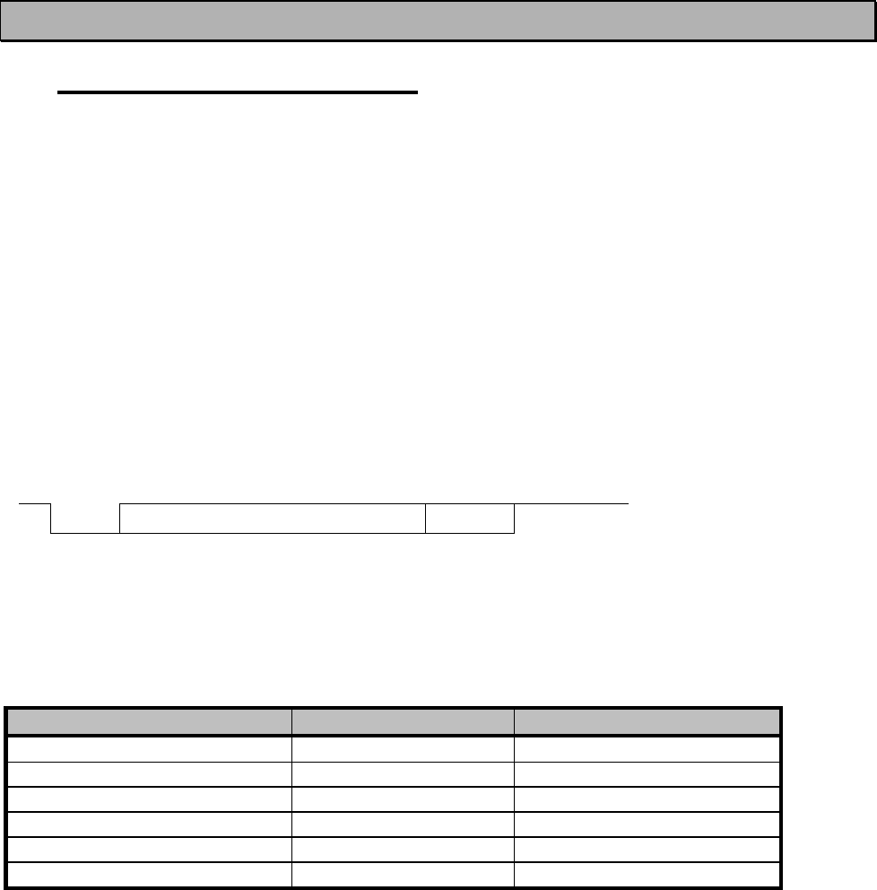
One character to be transmitted will thus contain a start bit; the data bits (which define the
specific character in question); an optional parity bit and one or two stop bits. The overall length
of one character is therefore 10, 11 or 12 bits. This should be taken into account when
calculating the data throughput capability of a system. In other words, the number of start, stop
and parity bits must be considered. A useful rule of thumb is that at a data transfer speed of
9600 bps, the transmission of one character will require roughly one millisecond (1 ms).
Start Data Parity End
Asynchronous character data format
Example: With an 8-bit data character length and taking, for example, a decimal value of
”204”, (which corresponds to a binary value of ”11001100”) and with a start bit value of ”0”,
parity bit set to either “NO” (NONE), ”0” or ”1” and with a stop bit value of ”1”, the possible
combinations are listed in the table below:
DATA FORMAT CHARACTER
CHARACTER LENGTH
8 bit, no parity, 1 stop bit
0110011001
10 bit
8 bit, even parity, 1 stop bit 01100110001
11 bit
8 bit, odd parity, 1 stop bit
01100110011
11 bit
8 bit, no parity, 2 stop bits
01100110011
11 bit
8 bit, even parity, 2 stop bits 011001100011
12 bit
8 bit, odd parity, 2 stop bits 011001100111
12 bit
If the settings of data speed, character length, parity or the number of stop bits differ between
the radio modem and the terminal, errors will be introduced into the transferred data. The serial
port settings of each individual radio modem in a system can all be different apart from the data
length setting (7, 8 or 9 bits), which must always be the same in each individual radio modem.
In other words, the serial port used, the data transfer speed, parity and number of stop bits; can
be different in different parts of a same system. This is especially useful where one part of the
system uses an RS-485 serial port and another part uses the RS-232 serial port. In other words,
radio modems may also be utilised as serial port adapters in addition to the more common role
of wireless data transfer.
The serial port settings can be changed in the Programming Mode.

SATELLINE-M3-TR1
User Guide, Version 1.4
26
6.2 Handshake lines
When using the RS-232 serial interface, handshake signals can be used to control data transfer.
Handshake signals are used, for example, by the radio modem to inform the terminal that the
radio channel is busy, and that it cannot initiate transmission. The terminal can also control the
radio modem via RTS-line.
Line Direction
CTS To terminal
RTS To modem
CD To terminal
A common way of using handshaking signals is to monitor the CTS-line and ignore the others.
Usually the terminal is fast enough to handle the data received by the radio modem, so the use
of RTS-line is not necessary.
Handshaking is not needed if the system protocol is designed to prevent collisions (data
contention) by the use of polling, or if there is little traffic and also if there is no harm from
occasional data contention situations (several radio modems try to transmit at the same time).
6.2.1 CTS-line
The options for CTS-line are:
1) Clear To Send
CTS is active when the radio modem is ready to accept data for new transmission. CTS will shift
into inactive state during data reception and transmission.
2) TX buffer state
CTS will shift into inactive state only if the radio modem’s TX buffer is in danger of overflowing.
This typically happens when the serial interface data transfer speed is greater than the radio
interface transfer speed and the size of transmitted messages is large.
6.2.2 CD-line
The options for CD-line are:
1) RSSI-threshold
CD is active whenever a signal with a level exceeding the level required for reception exists on
the radio channel. It doesn’t make any difference if the signal is an actual data transmission, a
signal of a radio transmitter not belonging to the system, or even an interference signal caused
for example, by a computer or a peripheral device. CD is also active when the radio modem in
question is transmitting.

SATELLINE-M3-TR1
User Guide, Version 1.4
27
2) Data on channel
CD will switch to active state only after recognition of a valid data transmission. CD will not
react to interference signals.
3) Always ON
CD is always in the active state. This option can be used with terminal equipment, which use the
CD-line as an indicator of an active connection (the radio modem can transmit and receive at
any time).
6.2.3 RTS-line
The options for RTS-line are:
1) Ignored
RTS-line status is ignored.
2) Flow control
The radio modem transmits data to the terminal device only when the RTS-line is active. Non-
active state of the RTS-line will force the radio modem to buffer the received data. This option is
used if the terminal device is too slow to handle data received from the radio modem.
3) Reception control
RTS-line controls the reception process of the radio modem. An active RTS-line enables
reception (as normal). Non-active RTS-line will interrupt reception process immediately, even if
the radio modem is receiving a data packet. This option is used to force the radio modem into
WAIT State for an immediate channel change.
6.3 Timing and delays during data transmission
When using a radio modem for data transmission, certain delays will be formed through the use
of a radio interface and from the radio modem circuitry itself. These delays exist when the radio
modem switches from Standby Mode to Data Transfer Mode and during reception and
transmission of data. For detailed delay values in each case see Appendix B.
6.3.1 Data buffering in the radio modem
Whenever the radio modem is in Data Transfer Mode it monitors both the radio channel and the
serial interface. When the terminal device starts data transmission the radio modem switches to
transmission mode. At the beginning of each transmission a synchronisation signal is transmitted
and this signal is detected by another radio modem, which then switches into receive mode.
During the transmission of the synchronisation signal the radio modem buffers data into its
memory. Transmission ends when a pause is detected in the data sent by the terminal device,
and after all buffered data has been transmitted. When the serial interface speed is the same or
slower than the speed of the radio interface, the internal transmit buffer memory cannot
overflow. However, when the serial interface speed exceeds the speed of the radio interface,
data will eventually fill transmit buffer memory. In this instance, it will take a moment after the

SATELLINE-M3-TR1
User Guide, Version 1.4
28
terminal device has stopped transmission of data for the radio modem to empty the buffer and
before the transmitter switches off. The maximum size of transmit buffer memory is one kilobyte
(1 kB). If the terminal device does not follow the status of the CTS-line and transmits too much
data to the radio modem, the buffer will be emptied and the transmission is restarted.
In the receive mode, the buffer works principally in the above described way thus evening out
differences in data transfer speeds. If the terminal device transmits data to a radio modem in
receive mode, the data will go into transmit buffer memory. Transmission will start immediately
when the radio channel is available.
6.3.2 Pause length
The modem recognises a pause on the serial line (a pause is defined as a time with no status
changes on the RS-232 interface TD-line). The pause detection is used as criteria for:
o End of radio transmission - When the transmit buffer is empty and a pause is detected,
the modem stops the transmission and will then change the radio to the receive mode.
o SL-command recognition - For a SL-command to be valid, a pause must be detected
before the actual “SL…” character string.
o User address recognition - In order for the start character to be detected, a pause must
precede it in transmission.
Traditionally, in asynchronous data communication, pauses have been used to separate serial
messages from each other. However, the use of non-real-time operating systems (frequently
used on PC-type hardware) often adds random pauses, which may result in the user data
splitting into two or more separate RF transmissions. This may cause problems especially in the
systems including repeater stations.
In order to match the operation of the radio modem to the user data, the Pause length
parameter can be adjusted on the programming menu. It may have any value between 3 and
255 characters. The default value is 3 characters.
Notes:
o The absolute time of Pause length is depending on the serial port settings. For example,
1 character is ~1.04 ms at 9600 bps / 8N1 (10 bits).
o The maximum absolute time is always 170 ms independent from the value of the Pause
length given in the set-up.
o An increase in the Pause length increases the round trip delay of the radio link
correspondingly; this is due to the fact that the radio channel is occupied for the time of
the Pause length after each transmission (the time it takes to detect a pause). If this is not
acceptable, the TX delay setting may also be useful in special cases.

SATELLINE-M3-TR1
User Guide, Version 1.4
29
6.3.3 TX delay
The radio modem can be configured to delay the beginning of a radio transmission by
1...65000 ms. This function can be used to prevent packet contention in a system, where all
substations would otherwise answer a poll of a base-station simultaneously. During this delay
data sent to the radio modem is buffered. Although the priority setting is "RX" , radio modem is
prevented to change over to receiving mode during the period of the TX delay.If this function is
not needed, the delay time should be set to 0 ms.
6.4 Tests
The radio modem can be switched to the Test Mode, where it will send a test packet on the
radio channel. The test packet is a normal data transmission, which can be used, for example,
when directing antennas during system installation.
When the test packet transmission has been switched on and saved by using the Programming
Mode, the transmitting radio modem needs only a power supply and an antenna.
If the channel spacing of the radio modems is 25 kHz, it is recommended to use 38400 bps as
a serial data speed of the receiving radio modem. In the case of 12.5 / 20 kHz channel spacing
the data speed of 19200 bps is recommended.
There are two Test Modes:
Short data block test
In this test mode the radio modem sends a short test string, which is preceded by a consecutive
number, and it ends to the line feed character. The short data block is repeated continuously
after 1 s break.
Short data block test is suitable for running data communication tests. Error-free reception of
data can be monitored using a suitable terminal program.
Example of a short data blocks:
00 This is a testline of SATELLINE -3AS-TR1 radio modem
01 This is a testline of SATELLINE -3AS-TR1 radio modem
02 This is a testline of SATELLINE -3AS-TR1 radio modem
Long data block test
Long data block consists of character strings, which are repeated without breaks 50 s time
period. After 10 s break the test transmission is started again.
Long block data test can be used for measuring Tx output power, standing wave ratio (SWR) of
the antenna system or received signal strength at Rx stations. Please note that SATELLINE -3AS-
TR1 Epic has to be the version equipped with a cooling element if Long block data test is set on
at higher than 1 W Tx output power.
SATELLINE-M3-TR1
User Guide, Version 1.4
30
Example of a long data blocks:
This is a long testline of SATELLINE -3AS-TR1 radio modem
This is a long testline of SATELLINE -3AS-TR1 radio modem
This is a long testline of SATELLINE -3AS-TR1 radio modem

SATELLINE-M3-TR1
User Guide, Version 1.4
31
7 SETTINGS
The configuration of SATELLINE -3AS-TR1 radio modems can be easily changed. Simply by
connecting the Mode pin to ground (GND) the radio modem will switch into Programming
Mode. Serial port PORT 1 is used whenever the radio modem is in the Programming Mode. The
serial port settings are 9600 bps, N, 8,1 (data transfer speed 9600 bps, no parity, character
length 8 bits and one (1) stop bit).
If the SL-command function has been activated active radio channel and addresses can be
changed without switching the radio modem into Programming Mode. Serial port settings will
remain as those defined previously when the radio modem was in Programming Mode.
7.1 Changing parameters using a terminal device
PORT 1 of the radio modem is connected to a terminal device or a PC, which is in terminal
emulation state. (This can be accomplished by using a suitable program such as the SaTerm
program or the Windows™ Hyper Terminal program). Check the wiring of the serial port
connection cable. Terminal device serial port settings must be set to 9600 bps, N, 8, 1 (data
transfer speed 9600 bps, no parity, data length 8 bits and one (1) stop bit). MODE-pin is then
connected to ground (GND). Following this the radio modem will transmit the following
message to the terminal (certain configuration settings might differ from the ones shown):
***** SATELLINE-3AS M3-TR1 *****
SW:06.16.3.34 / HW: SPL0005B / PV: 00.00 / IM: 02 /
--------------------------------------------------------------------------------
Current settings
----------------
1) Radio frequency 438.0000 MHz ( CF 438.0000 MHz, spacing 25 kHz )
2) Radio settings Tx power level 1000 mW / Signal threshold -112 dBm / FCS OFF /
TX start delay 0 ms / Diversity RX OFF / EPIC PWRSave OFF /
Compatibility Satel 3AS
3) Addressing RX address OFF / TX address OFF /
RX address to RS port OFF / TX address autoswitch OFF
4) Serial port 1 ON / 19200 bit/s / 8 bit data / None parity / 1 stop bit
5) Serial port 2 OFF / 19200 bit/s / 8 bit data / None parity / 1 stop bit (RS-232)
6) Handshaking CTS Clear to send / CD RSSI-threshold /
RTS Ignored / Pause length 3 bytes
7) Additional setup Error correction OFF / Error check OFF / Repeater OFF /
SL-commands ON / Priority TX / Full CRC16 check OFF
8) Routing OFF
9) Tests OFF
A) Restore factory settings
E) EXIT and save settings
Q) QUIT without saving
Enter selection >
More information at Satel.com

SATELLINE-M3-TR1
User Guide, Version 1.4
32
7.2 Updating Firmware
The Firmware can be updated in two ways:
• By using terminal program. Instructions to use this method are given by request.
• By using Configuration Manager (CM), which requires The SATEL Configuration Manager,
a cable adapter between the module and a PC with serial port.
The firmware of SATELLINE-3AS-TR1 is stored in a flash memory. If needed the software is easily
updated by SaTerm terminal program. Please see the user guide of SaTerm for more details.
The SATEL Configuration Manager is configuration and setup software that has been explained
in a separate User Manual.
7.3 Basic configuration and installation
The radio modem is shipped with the following default settings (unless otherwise specifically
ordered):
DEFAULT VALUES OF THE ADJUSTABLE SETTINGS ( the user can change these settings later on )
Setting Default value
Notes
Operating frequency 438.000 MHz
Range: 403-473 MHz
Channel Spacing 25 kHz Range:12.5kHz, 20kHz, or 25 kHz
Tx Power 1000 mW Range: 100, 200, 500 or 1000 mW
Protocol SATEL 3AS SATEL 3AS, Option1=PCC 4-FSK, Option
2=PCC GMSK, 3=TrimTalk
Addressing RX Address OFF /
TX Address OFF
Tx-Delay 0 ms
Signal threshold -115 dBm
SyncInterval default (=21845 bytes)
Rx-Delay 0 ms
Pause length 3 characters
FEC OFF
Error check OFF
Error correction OFF
Serial port 1 settings Port function=DATA
Data speed=9600 bps
Data bits=8
Parity=None
Stop bits=1
Pause length=3 bytes
NOTE! To switch the radio modem back into Data Transfer Mode
the MODE-pin must be
disconnected from ground (GND).

SATELLINE-M3-TR1
User Guide, Version 1.4
33
Serial port 2 settings Port function=DATA
Data speed=9600 bps
Data bits=8
Parity=None
Stop bits=1
Pause length=3 bytes
Handshaking settings CTS=Clear to send
CD=RSSI threshold
RTS=Ignored
Handshaking lines apply to the DATA-port.
SL-commands ON
When creating a test connection, you can also use the Windows-based SATEL Configuration
Manager, (available for free from authorised SATEL dealers or directly from SATEL Customer
Support).
Basic settings for the serial port of the host computer, when using a terminal program to
communicate with SATEL radio modems, are as follows: “COM1, 9600 bps, 8-bit data, none
parity, 1 stop bit”.
The power cable (+Vb and GND) must be connected to a power supply with a proper output
voltage and with a minimum output current of 2 A (for 6-9V PWR-module) and 1 A (for 6-30V
PWR-module).

SATELLINE-M3-TR1
User Guide, Version 1.4
34
8 SW-RELATED COMMANDS AND OPTIONS
8.1 Repeater mode and addressing
Repeaters and addressing may be used to extend the coverage area of a radio modem network,
and to direct messages to selected radio modems in the network. In large systems, with several
repeaters and formed repeater chains, it is often practical to use routing instead of plain
addresses.
More information at Satel.com
8.2 Message routing
This feature allows messages from terminal devices to be automatically routed over the radio
modem network to a specified recipient terminal.
More information at Satel.com
8.3 Virtual Mode Routing
More information at Satel.com
8.4 SL-Commands
An SL-command is a one continuous string of characters, which is separated from other data by
pauses that are equal or greater than time defined by Pause length parameter (default=3
characters) in the set-up. No extra characters are allowed at the end of an SL-command.
Serial interface settings are the same as in data transfer and MODE pin MUST NOT be
connected to ground (GND). SL-command is properly recognised also in the case when the
command string is terminated in <CR> (=ASCII character no. 13, Carriage Return, 0x0d) or
<CR><LF> (<LF> = ASCII char. no. 10, Line Feed, 0x0a). If multiple SL commands are sent
to the radio modem the next command can be given after receiving the response ("Ok" or
"Error") of the proceeding command. In addition, it is recommended to implement a timeout to
the terminal software for recovering the case when no response is received from the radio
modem.
When the power of a radio modem is switched off the configuration settings of a radio modem
always return to values defined initially using the Programming Mode, thus resetting any settings
changed using SL-commands during power on. It is however possible to save settings changed
by using SL-commands and to make them the new configuration settings.

SATELLINE-M3-TR1
User Guide, Version 1.4
35
The radio modem will acknowledge all commands by returning an "OK" (command carried out
or accepted) or the requested value, or an "ERROR" (command not carried out or interpreted as
erroneous) message.
8.4.1 Changing parameters using the SL-COMMANDS
The controlling terminal device can change the configuration settings of a radio modem. This is
accomplished with the help of SL-commands, which can be used during data transfer. SL-
commands can be used to change e.g. the frequency or addresses. It is also possible to
interrogate a radio modem in order to gain information concerning current settings that are in
use. The terminal device is either a PC or a programmable logic (PLC) together with suitable
(terminal) program. SL-commands must be enabled (in the set-up) before they can be used.
More information at Satel.com

SATELLINE-M3-TR1
User Guide, Version 1.4
36
9 APPENDIX A
A
SCII CHARACTER TABLE
D H
A
D H
A
D H
A
D
H
A
D
H
A
D H
A
0 0 NUL 43 2B + 86 56
V
129
81
172
A
C
215 D7
1 1 SOH 44 2C , 87 57
W
130
82
173
A
D
216 D8
2 2 STX 45 2D - 88 58
X
131
83
174
A
E
217 D9
3 3 ETX 46 2E . 89 59
Y
132
84
175
A
F
218 DA
4 4 EOT 47 2F
/
90 5A
Z
133
85
176
B0
219 DB
5 5 ENQ 48 30 0 91 5B
[
134
86
177
B1
220 DC
6 6
A
CK 49 31 1 92 5C
\
135
87
178
B2
221 DD
7 7 BEL 50 32 2 93 5D
]
136
88
179
B3
222 DE
8 8 BS 51 33 3 94 5E
^
137
89
180
B4
223 DF
9 9 HT 52 34 4 95 5F
_
138
8A
181
B5
224 E0
10
A
LF 53 35 5 96 60
`
139
8B
182
B6
225 E1
11 B
V
T 54 36 6 97 61
a
140
8C
183
B7
226 E2
12 C FF 55 37 7 98 62
b
141
8D
184
B8
227 E3
13 D CR 56 38 8 99 63
c
142
8E
185
B9
228 E4
14 E SO 57 39 9 100 64
d
143
8F
186
BA
229 E5
15 F SI 58 3A : 101 65
e
144
90
187
BB
230 E6
16 10 DLE 59 3B ; 102 66
f
145
91
188
BC
231 E7
17 11 DC1 60 3C < 103 67
g
146
92
189
BD
232 E8
18 12 DC2 61 3D = 104 68
h
147
93
190
BE
233 E9
19 13 DC3 62 3E > 105 69
i
148
94
191
BF
234 EA
20 14 DC4 63 3F ? 106 6A
j
149
95
192
C0
235 EB
21 15 NAK 64 40 @ 107 6B
k
150
96
193
C1
236 EC
22 16 SYN 65 41
A
108 6C
l
151
97
194
C2
237 ED
23 17 ETB 66 42 B 109 6D
m
152
98
195
C3
238 EE
24 18 CAN 67 43 C 110 6E
n
153
99
196
C4
239 EF
25 19 EM 68 44 D 111 6F
o
154
9A
197
C5
240 F0
26 1A SUB 69 45 E 112 70
p
155
9B
198
C6
241 F1
27 1B ESC 70 46 F 113 71
q
156
9C
199
C7
242 F2
28 1C FS 71 47 G 114 72
r
157
9D
200
C8
243 F3
29 1D GS 72 48 H 115 73
s
158
9E
201
C9
244 F4
30 1E RS 73 49 I 116 74
t
159
9F
202
CA
245 F5
31 1F US 74 4A J 117 75
u
160
A
0
203
CB
246 F6
32 20 SP 75 4B K 118 76
v
161
A
1
204
CC
247 F7
33 21 ! 76 4C L 119 77
w
162
A
2
205
CD
248 F8
34 22 " 77 4D M 120 78
x
163
A
3
206
CE
249 F9
35 23 # 78 4E N 121 79
y
164
A
4
207
CF
250 FA
36 24 $ 79 4F O 122 7A
z
165
A
5
208
D0
251 FB
37 25 % 80 50 P 123 7B
{
166
A
6
209
D1
252 FC
38 26 & 81 51 Q 124 7C
|
167
A
7
210
D2
253 FD
39 27 ' 82 52 R 125 7D
}
168
A
8
211
D3
254 FE
40 28 ( 83 53 S 126 7E
~
169
A
9
212
D4
255 FF
41 29 ) 84 54 T 127 7F
170
A
A
213
D5
42 2A * 85 55 U 128 80
171
A
B
214
D6
SATELLINE-M3-TR1
User Guide, Version 1.4
37
10 APPENDIX B
10.1 Functional delays
Function Delay (ms)
Wakeup time from STAND-BY to ON
(controlled by DTR line)
123 ms
(CTS active)
Wakeup time from Power OFF -> Power ON
(=ready to receive)
123
ms/typical
Serial interface, turnaround time of RS-232
0
Serial interface, turnaround time of RS-485
<1
ms
SL-Ping response time from remote modem
222 ms
10.2 Transmission related delays
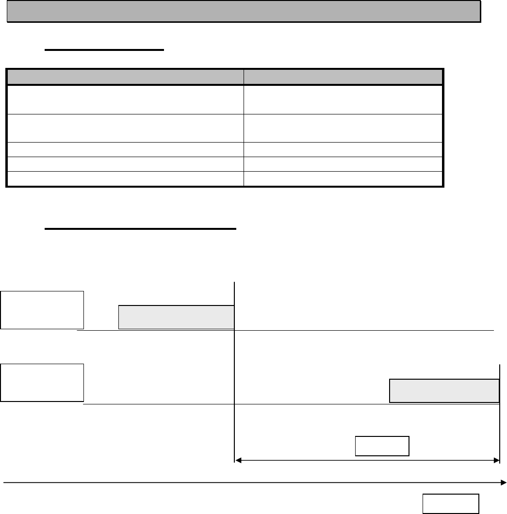
Delay from the end of transmission to the end of reception on the serial interface:
Modem 1
TD-line
Modem 2
RD-line
Delay
Time
start
start
DAT
A
DAT
A
SATELLINE-M3-TR1
User Guide, Version 1.4
38
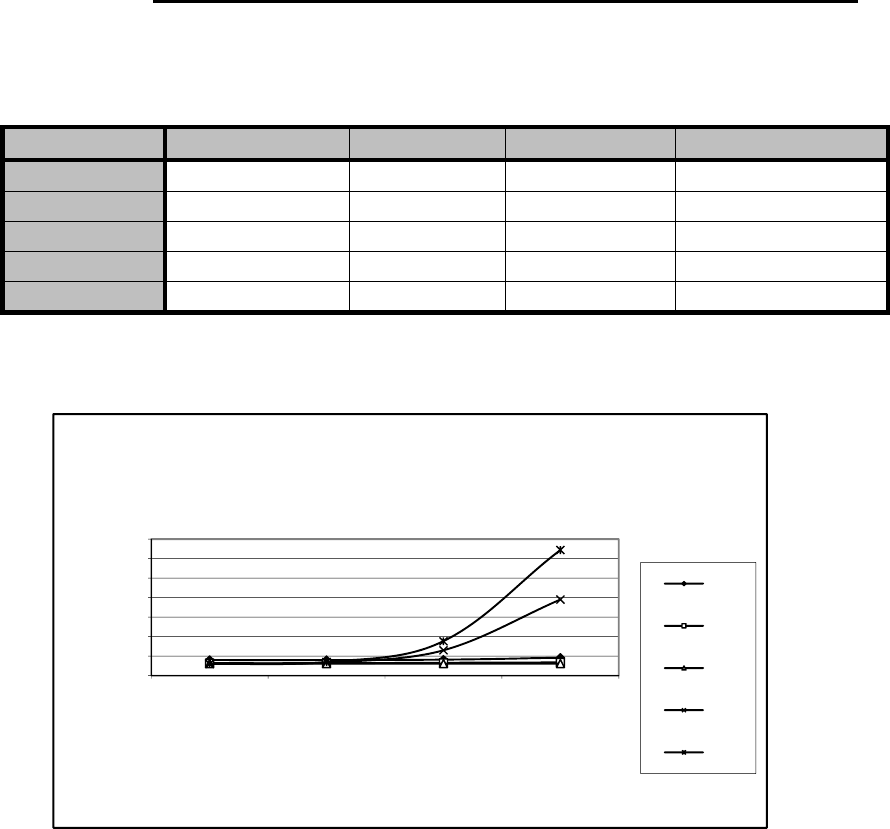
10.2.1 Transmission delays when using a 12.5 kHz radio channel
Transmission delays (ms) without FEC-function (Forward Error Correction).
Number of bytes sent
Bps 1 10
100
500
1200 40 40
29
22
4800 34 34
31
22
9600 32 32
32
27
19200 32 35
64
193
38400 32 36
91
352
Delays are in milliseconds and with a 10% margin.
0
50
100
150
200
250
300
350
1 10 100 500
Delay / ms
Number of Bytes
12.5 kHz radio channel without error correction
1200
4800
9600
19200
38400
SATELLINE-M3-TR1
User Guide, Version 1.4
39
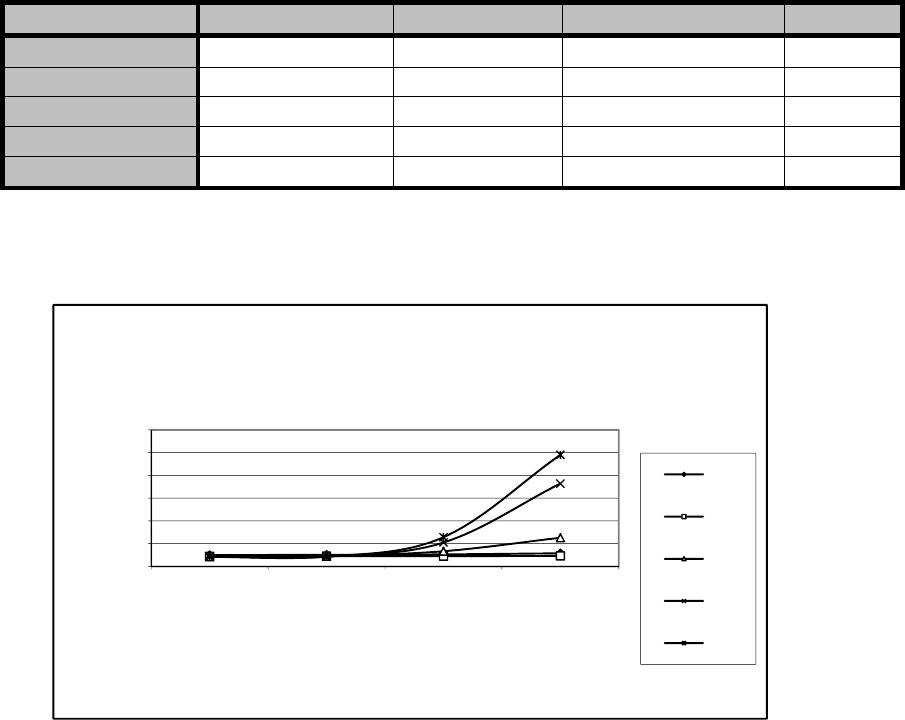
Transmission delays with FEC-function (Forward Error Correction).
Number of bytes sent
Bps 1 10
100
500
1200 52 49
48
50
4800 45 45
44
44
9600 44 44
68
121
19200 44 44
104
360
38400 48 48
132
496
Delays are in milliseconds and with a 10% margin.
0
100
200
300
400
500
600
1 10 100 500
Delays / ms
Number of Bytes
12.5 kHz radio channel with error correction
1200
4800
9600
19200
38400
SATELLINE-M3-TR1
User Guide, Version 1.4
40
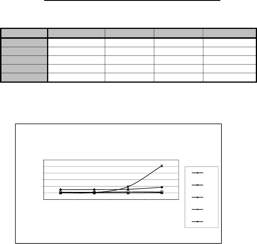
10.2.2 Transmission delays using a 25 kHz radio channel
Transmission delays without FEC-function (Forward Error Correction).
Number of bytes sent
Bps 1 10
100
500
1200 30 30
18
16
4800 23 23
21
12
9600 23 23
21
17
19200 22 22
22
19
38400 22 22
38
102
Delays are in milliseconds and with a 10% marginal.
0
20
40
60
80
100
120
1 10 100 500
Delay / ms
Number of Bytes
25 kHz radio channel without error correction
1200
4800
9600
19200
38400
SATELLINE-M3-TR1
User Guide, Version 1.4
41
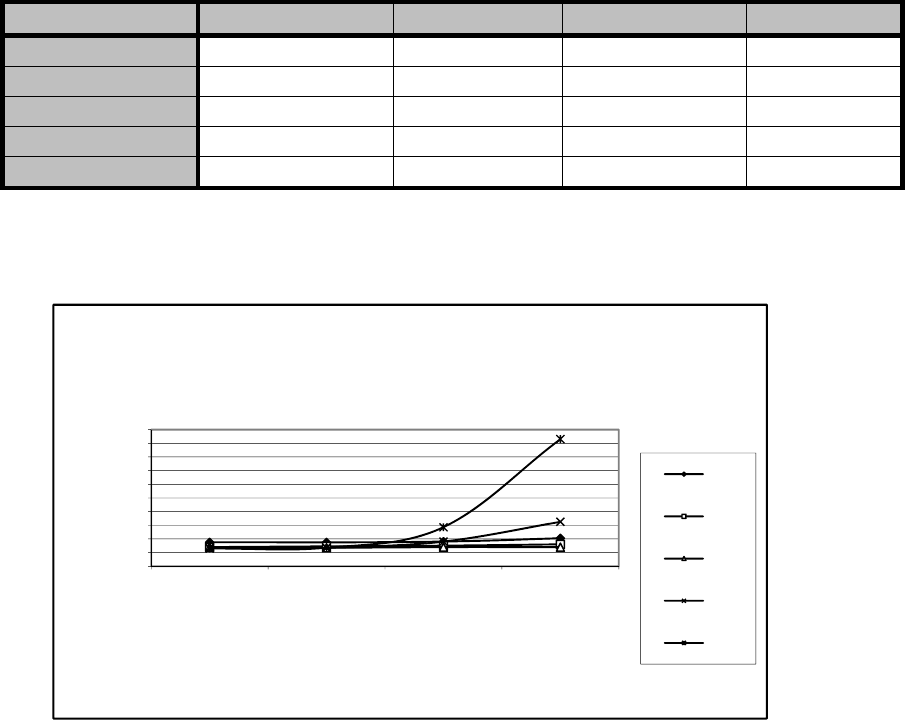
Transmission delays with FEC-function (Forward Error Correction).
Number of bytes sent
Bps 1 10
100
500
1200 35 34
29
30
4800 28 28
27
23
9600 28 28
28
23
19200 28 28
36
64
38400 27 27
58
185
Delays are in milliseconds and with a 10% margin.
0
20
40
60
80
100
120
140
160
180
200
1 10 100 500
Delay / ms
Number of Bytes
25 kHz radio channel with error correction
1200
4800
9600
19200
38400