Satel SATEL-TA23 Radio Data Modem User Manual 3AS User Guide
Satel Oy Radio Data Modem 3AS User Guide
UserManual.wiki
>
Satel
>
SATEL-TA23 User Manual
>
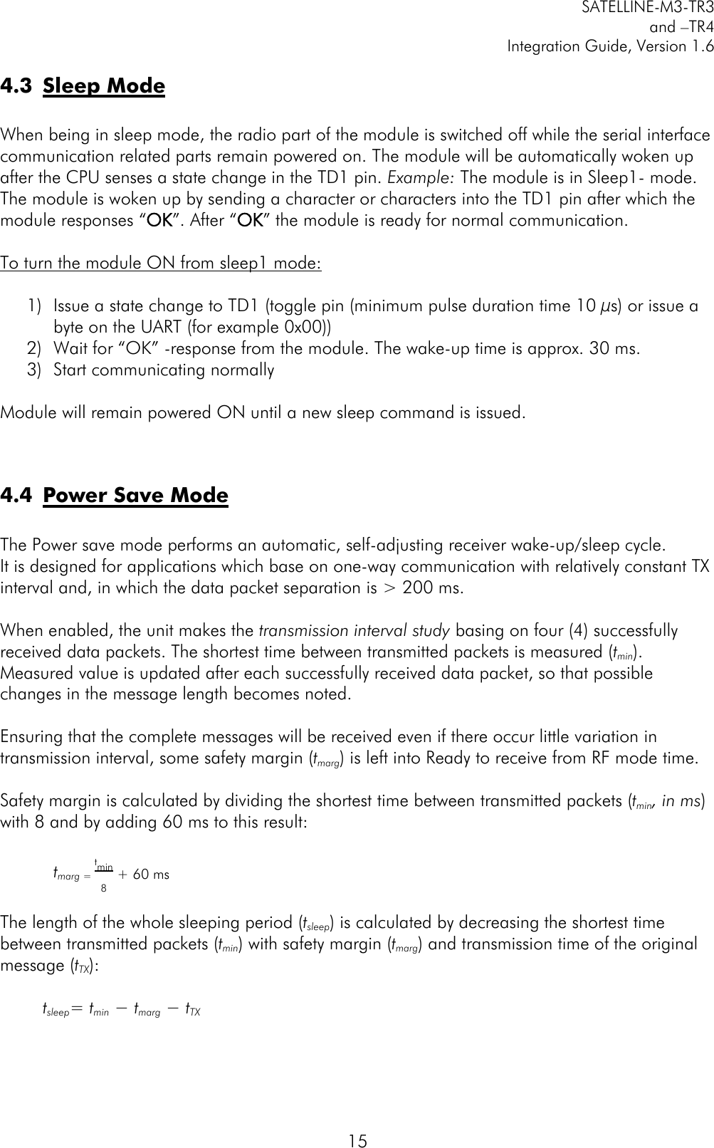
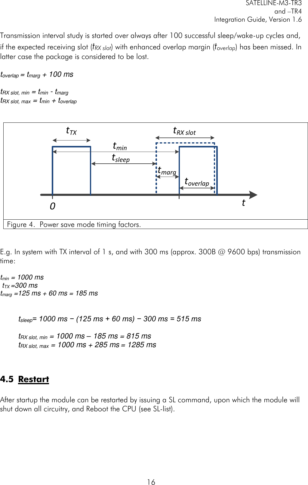
10 SATELLINE-M3-TR3_TR4_V_1_6
Contents
1.
User Manual
2.
User manual
3.
10 SATELLINE-M3-TR3_TR4_V_1_6
10 SATELLINE-M3-TR3_TR4_V_1_6
Navigation menu
Upload a User Manual
Namespaces
Wiki Guide
HTML
PDF
Info
Views
User Manual
Discussion / Help
Navigation
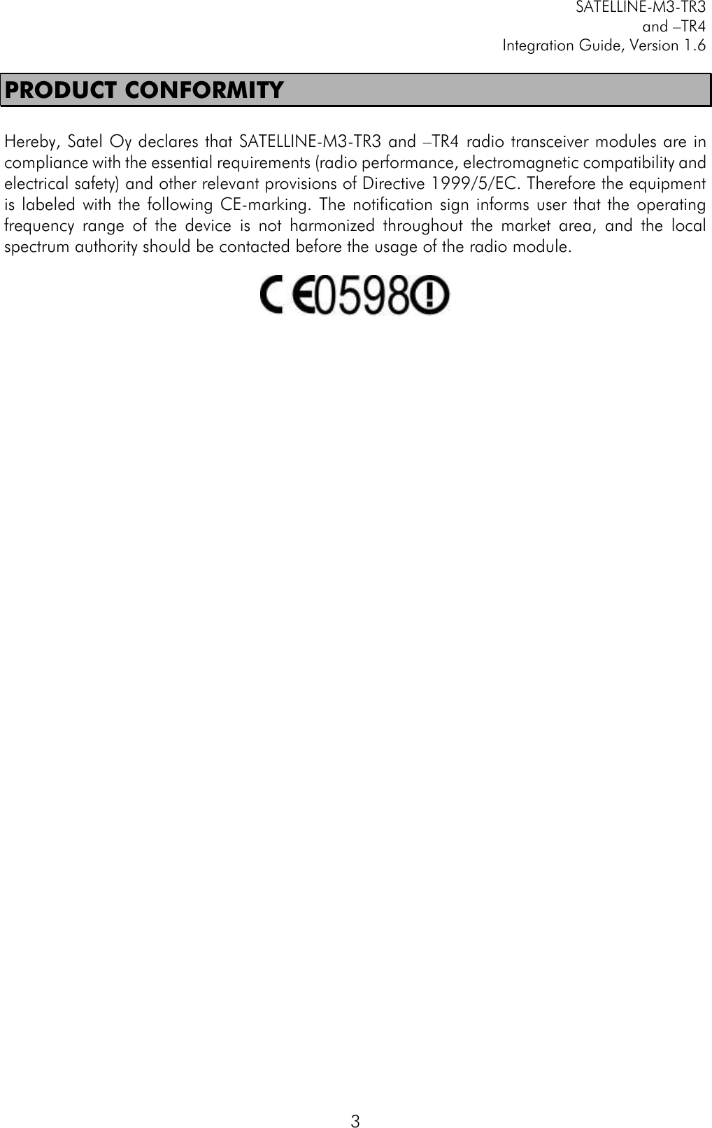
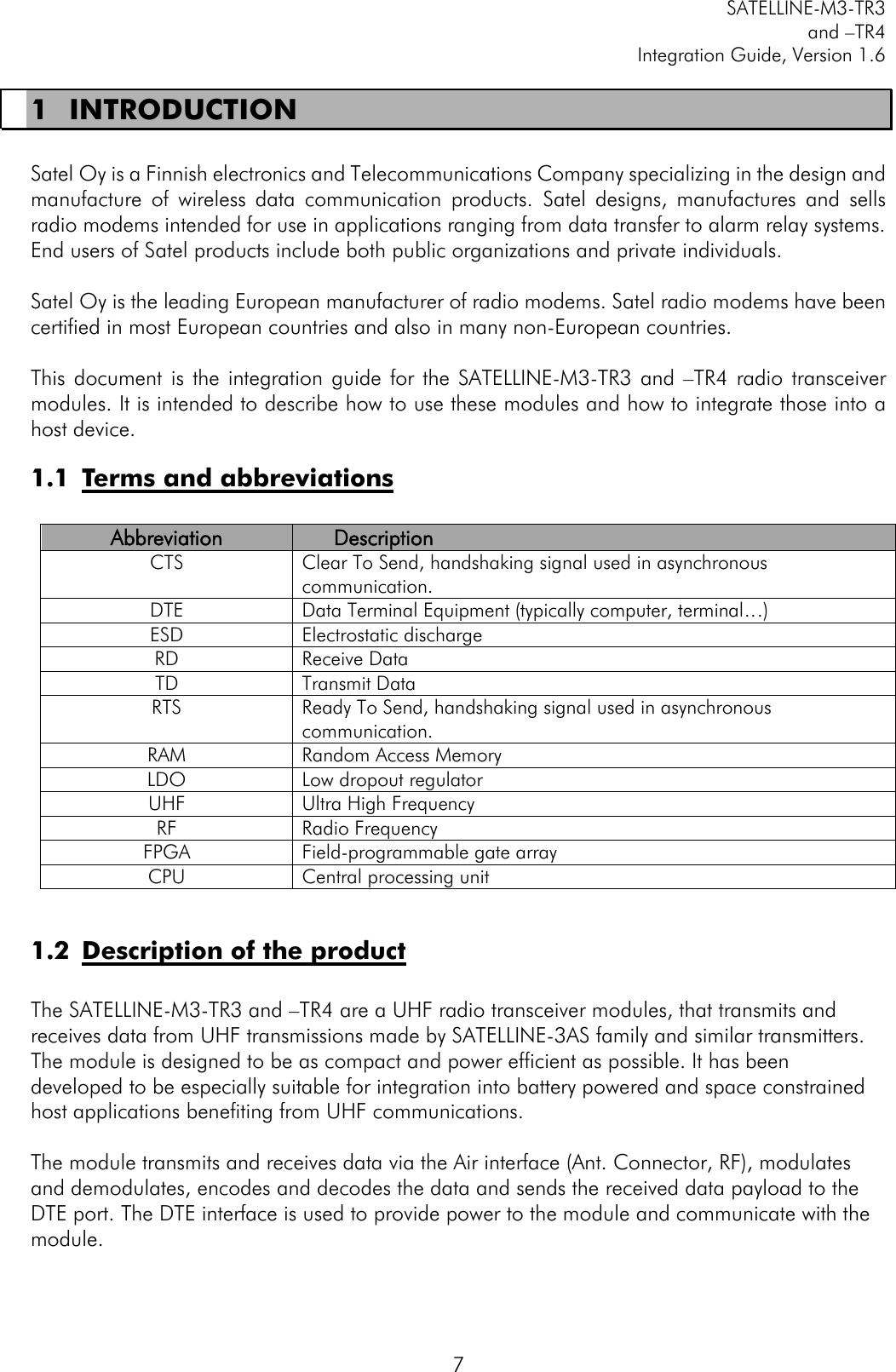
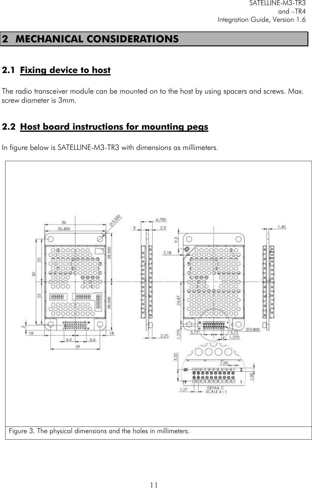
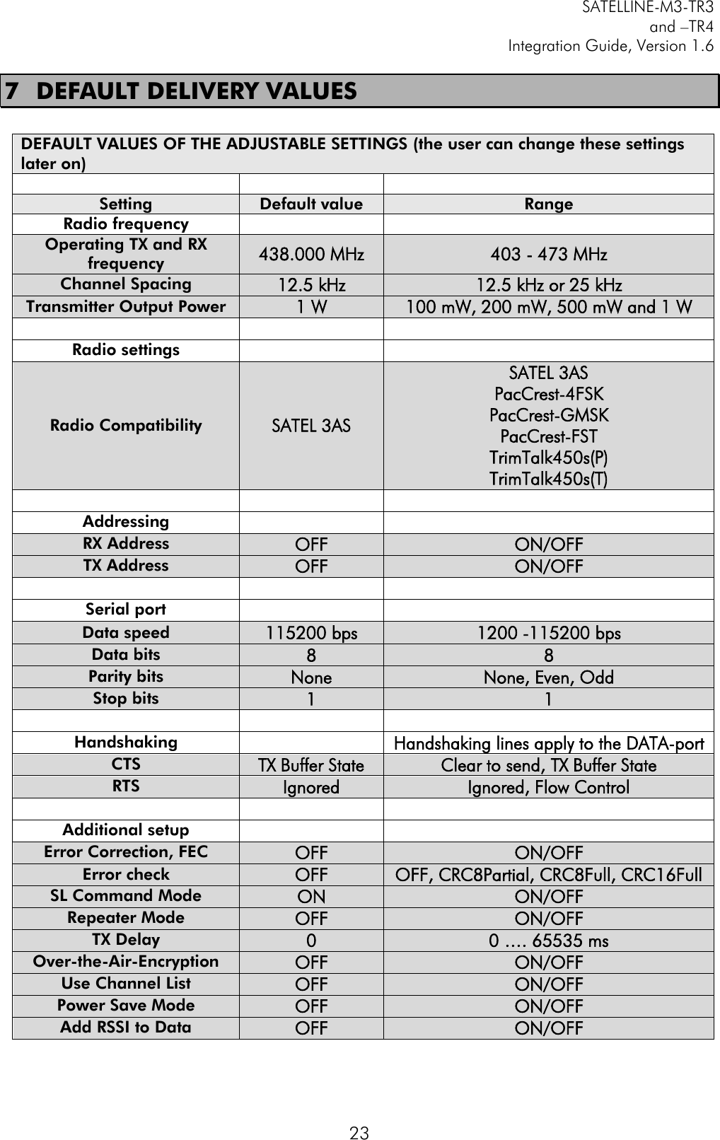
![SATELLINE-M3-TR3 and –TR4 Integration Guide, Version 1.6 26 9 APPENDIX 9.1 SL COMMANDS Category Command Description Response Addressing SL#A? Show all addresses (RX1, RX2, TX1, TX2) "xxxx,yyyy,zzzz,vvvv" Addressing SL#A=xxxx, yyyy, zzzz,vvvv Set RX/TX addresses (RX1, RX2, TX1, TX2) "OK" or "ERROR" Addressing SL#I? Get primary addresses (TX1, RX1) "xxxx;yyyy" Addressing SL#I=xxxx Set all addresses (RX1, RX2, TX1, TX2) to value xxxx [0000....ffff] "OK" or "ERROR" Addressing SL#P? Get primary transmit address (TX1) and primary receive address (RX1) "xxxx;yyyy" Addressing SL#P=xxxx;yyyy Set primary transmit address (TX1) to value xxxx and primary receive address (RX1) to value yyyy [0000....ffff] "OK" or "ERROR" Addressing SL#Q? Get TX address mode "0" = TX address OFF "1" = TX address ON Addressing SL#Q=x Set TX address ON/OFF. Values of x are: "0" = TX address OFF "1" = TX address ON "OK" or "ERROR" Addressing SL#R? Get primary receive address (RX1) "yyyy" Addressing SL#R=xxxx Set receive addresses (RX1, RX2) to value xxxx [0000....ffff] "OK" or "ERROR" Addressing SL#S? Get secondary transmit address (TX2) and secondary receive address (RX2) "xxxx;yyyy" Addressing SL#S=xxxx;yyyy Set secondary transmit address (TX2) to value xxxx and secondary receive address (RX2) to value yyyy [0000....ffff] "OK" or "ERROR" Addressing SL#T? Get primary transmit address (TX1) "xxxx" Addressing SL#T=xxxx Set transmit addresses (TX1, TX2) to value xxxx [0000....ffff] "OK" or "ERROR" Addressing SL#W? Get RX address mode "0" = RX address OFF "1" = RX address ON Addressing SL#W=x Set RX address ON/OFF. Values of x are: "0" = RX address OFF "1" = RX address ON "OK" or "ERROR" ChannelList SL$A=1 Go to channel list default channel "OK" or "ERROR"](https://usermanual.wiki/Satel/SATEL-TA23.10-SATELLINE-M3-TR3-TR4-V-1-6/User-Guide-2968788-Page-27.png)
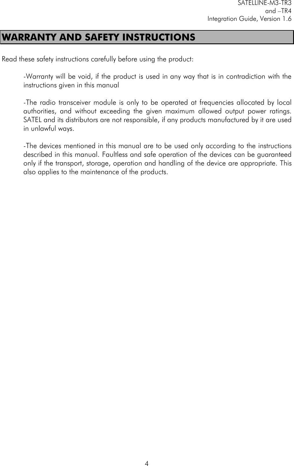
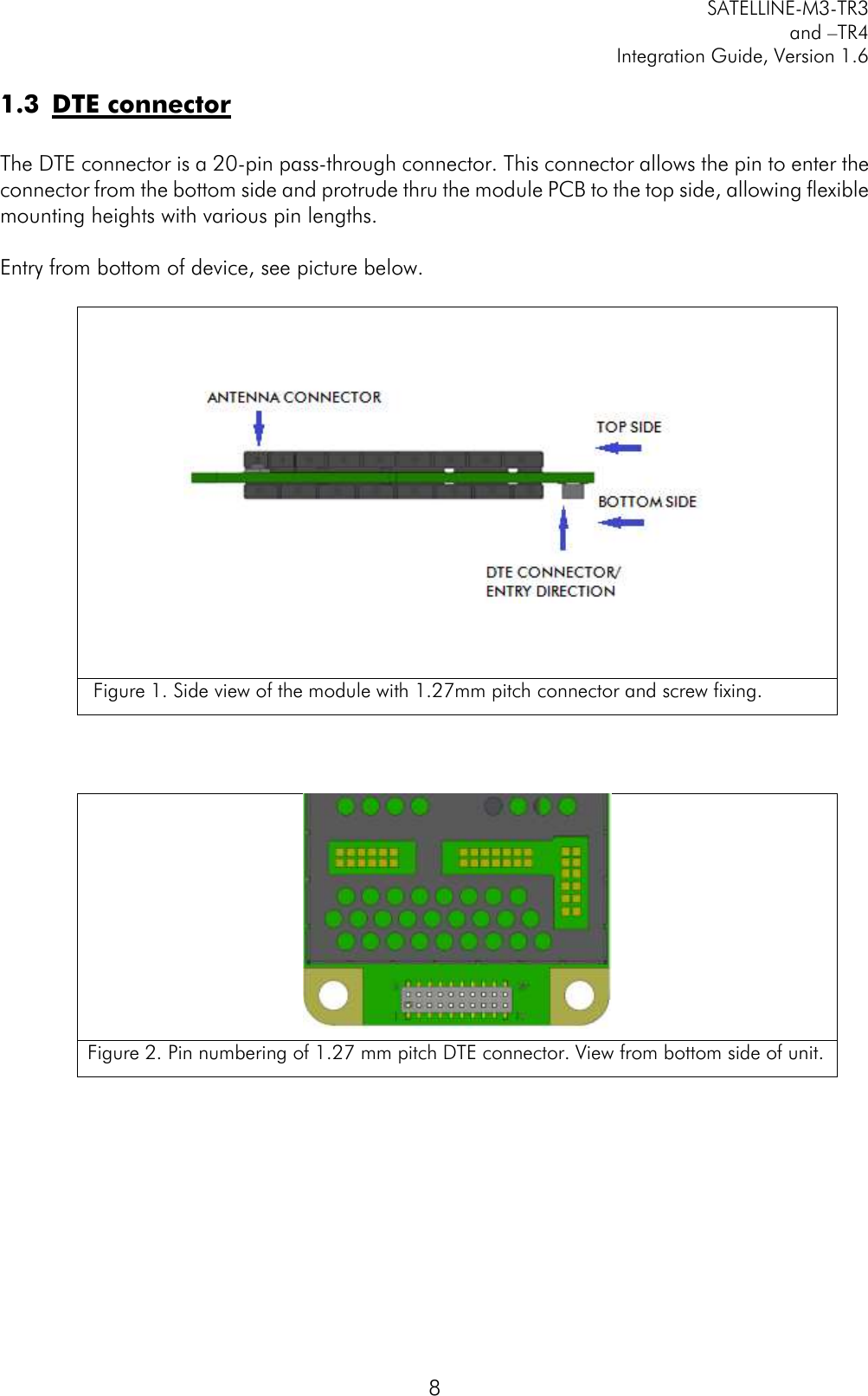
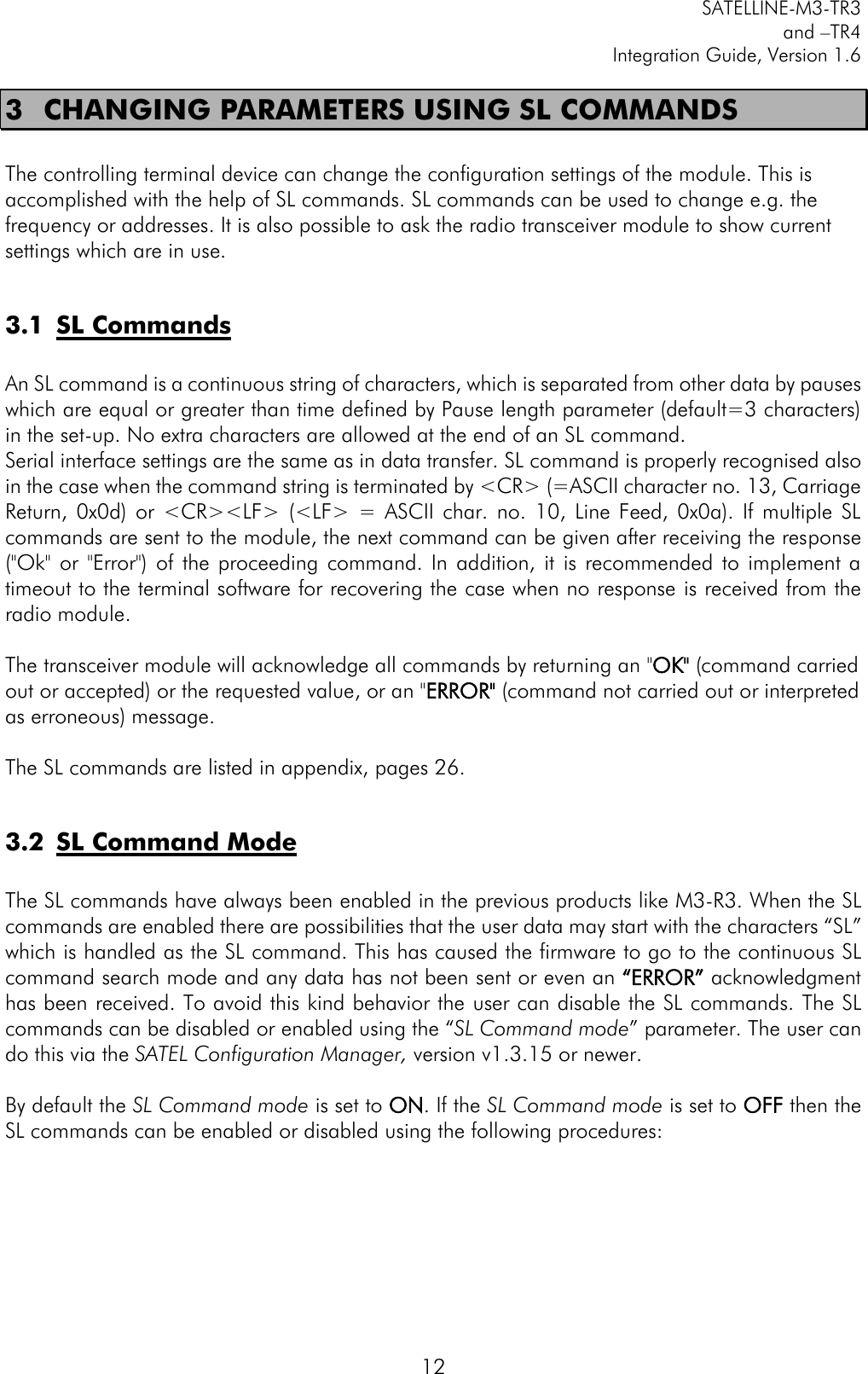
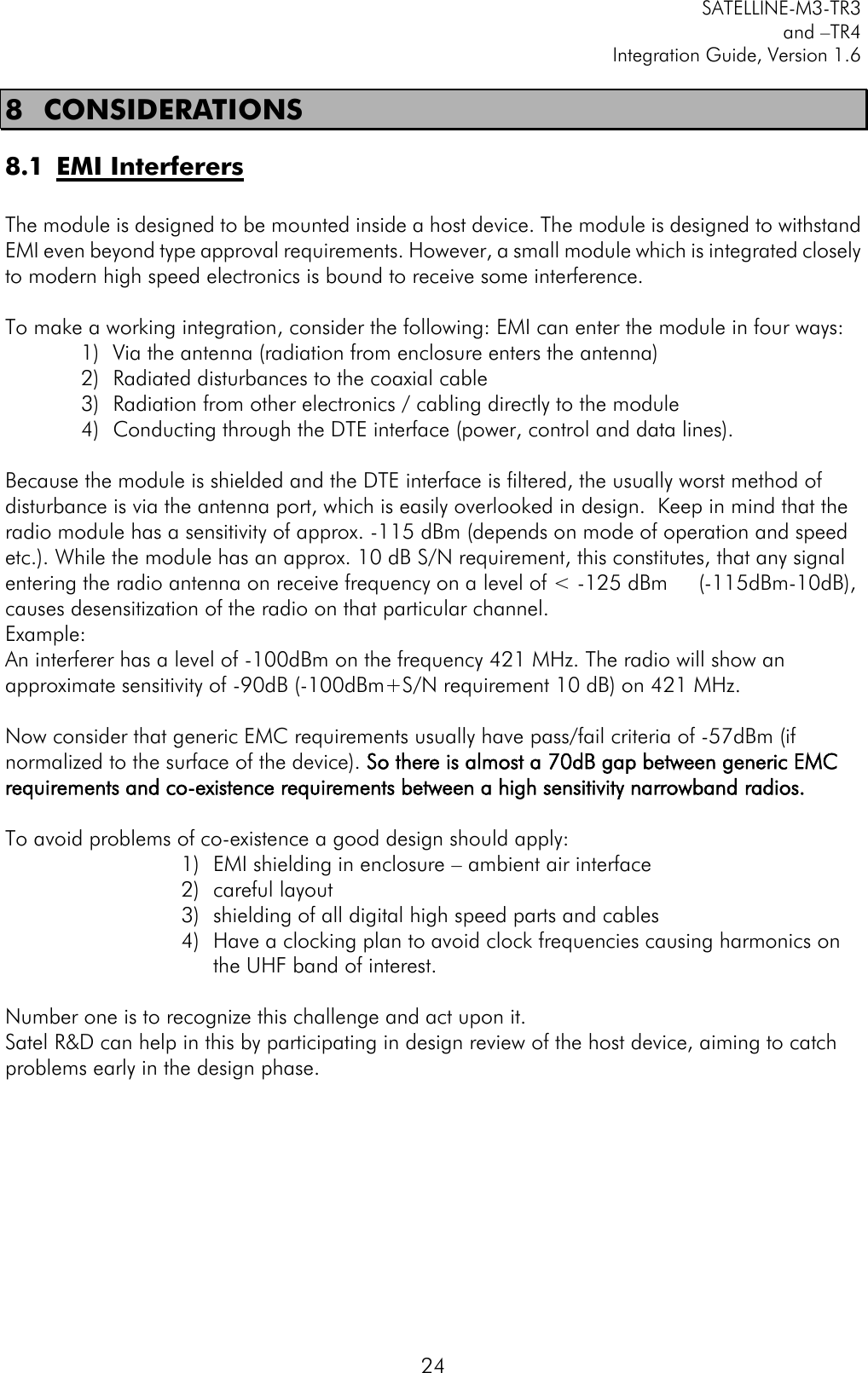
![SATELLINE-M3-TR3 and –TR4 Integration Guide, Version 1.6 27 ChannelList SL$C? Get number of channels in channel list decimal number ChannelList SL$C=nn Set number of channels in channel list. nn = 0...40, 0 clears the whole list "OK" or "ERROR" ChannelList SL$D? Get channel list default channel number decimal number ChannelList SL$D=n Set channel list default channel, n is channel number "OK" or "ERROR" ChannelList SL$E=1 Search free channel Modem searches for next traffic-free channel. Listening time of traffic is about 2 seconds Modem shows next free channel by activating command again "OK" followed by “channel n is free” Value of n is channel number of next free channel on channel list ChannelList SL$F? Get active channel number decimal number ChannelList SL$F=n Set modem to channel number n in channel list "OK" or "ERROR" ChannelList SL$L?nn Get channel info. Index nn=[0...(number of channels-1)] Channel number, Frequency, Channel width, Tx Power For example: "CH 1, 430.150000 MHz, 25.0 kHz, 100 mW\0D" ChannelList SL$L=Iaa,Nbbbbbb,Fccc.cccccc,Wdd.ddd,Peeeee<CR> I = Index field aa = 0...39 //Future reservation 0...255 N = Channel number field bbbbbb = -32767...32767 F = Tx/Rx Frequency field ccc.cccccc = Tx/Rx Frequency in MHz (only numbers or "." allowed, "," is not allowed) W = Channel spacing/width field ddddd = 12.5, 20 or 25 (unit is kHz, trailing decimals are tolerated e.g. "25", "25.0", "25.00" and "25.000" are all valid) P = Transmitter power field eeeee = 0...35000 (modem rounds the value to the closest applicable) Note: 0 means "don't care" value for power. <CR> = Carriage return character "OK" or "ERROR" ChannelList SL$M? Get status of channel list. 0 = Not in use, 1 = Channel list in use "0" or "1" ChannelList SL$M=n Set status of channel list. 0 = Not in use, 1 = Channel list in use "OK" ChannelList SL$R? Get listening time (seconds) of Search free channel function decimal number](https://usermanual.wiki/Satel/SATEL-TA23.10-SATELLINE-M3-TR3-TR4-V-1-6/User-Guide-2968788-Page-28.png)
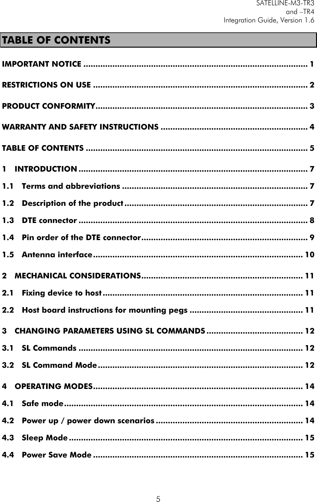
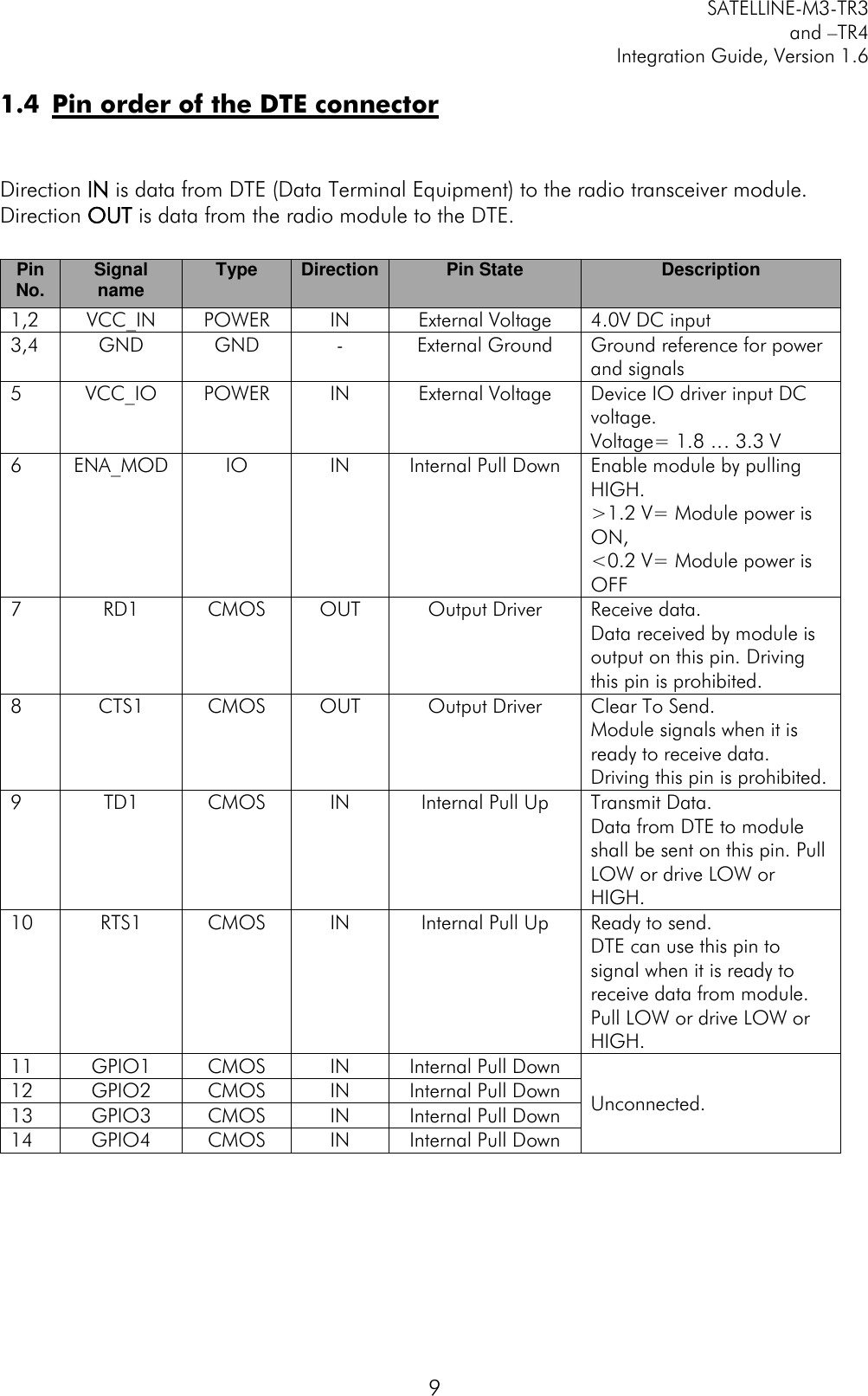
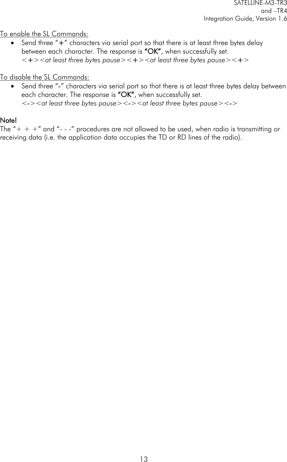
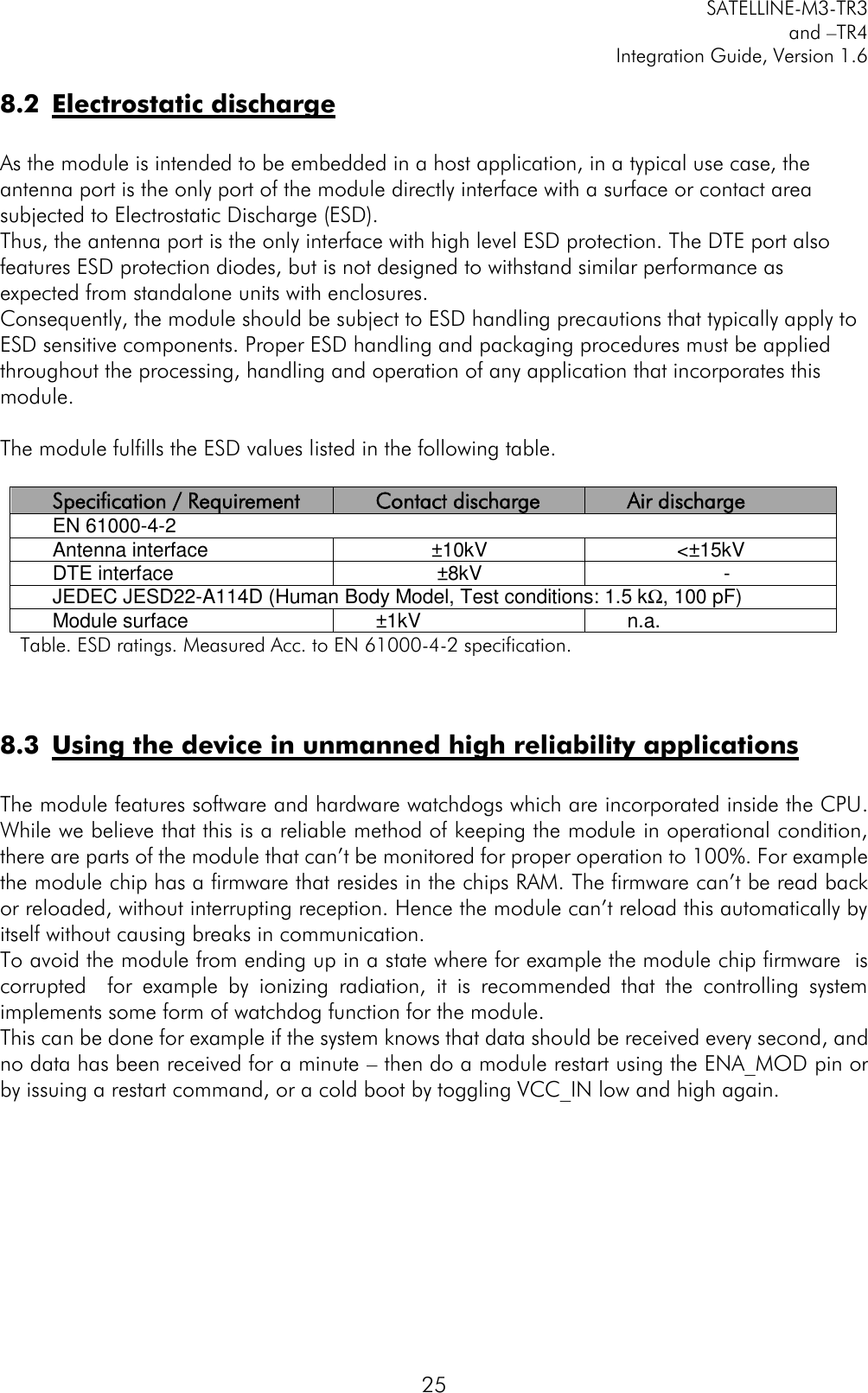
![SATELLINE-M3-TR3 and –TR4 Integration Guide, Version 1.6 30 RadioProperty SL%E? Get status of Error check and Full CRC16 check modes "0" Error check off "1" CRC8 Partial "2" CRC8 Full "3" CRC16 Full RadioProperty SL%E=x Set Error check and Full CRC16 check modes. Value of x is: "0" Error check off "1" CRC8 Partial "2" CRC8 Full "3" CRC16 Full "OK" or "ERROR" RadioProperty SL%R? Get region code setting/status 0,0 = Default, 1,1 = US, 1,2 = US & Illegal radio setting combination (TX is disabled) RadioProperty SL@D? Get Tx delay (ms) For example "0 ms" or "50 ms" RadioProperty SL@D=n Set Tx delay (ms), n is [0…65535] "OK" or "ERROR" RadioProperty SL@E? Get supported radio compatibility modes. List of numbers, separated by commas, showing the supported modes: 0=Satel3AS, 1=PacCrest 4FSK, 2=PacCrest GMSK, 3=TrimTalk, 4=TrimTalk Trimble, 5=PCC FST For example: "0,1" indicates that the modem supports Satel3AS and PacCrest 4FSK protocols. RadioProperty SL@F? Get noise level of radio channel "-xxx dBm" RadioProperty SL@M? Get repeater function "O" = Repeater OFF(character O) "R" = Repeater ON RadioProperty SL@M=x Set repeater function. Values of x are: "O" = Repeater function OFF(character O) "R" = Repeater function ON "OK" or "ERROR" RadioProperty SL@P? Get transmitter output power One of these values "100mW", "200mW", "500mW", "1000 mW" RadioProperty SL@P=nnnnn Set RF output power (mW) For example "SL@P=100" sets 100 mW transmitter output power. "100" sets 100 mW transmitter output power. "200" sets 200 mW transmitter output power. "500" sets 500 mW transmitter output power. "1000" sets 1000 mW transmitter output power. "OK" / "ERROR"](https://usermanual.wiki/Satel/SATEL-TA23.10-SATELLINE-M3-TR3-TR4-V-1-6/User-Guide-2968788-Page-31.png)
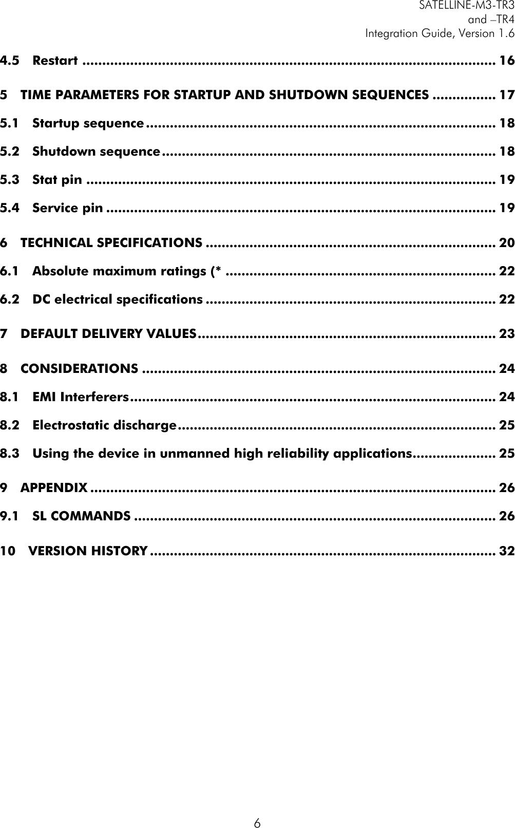
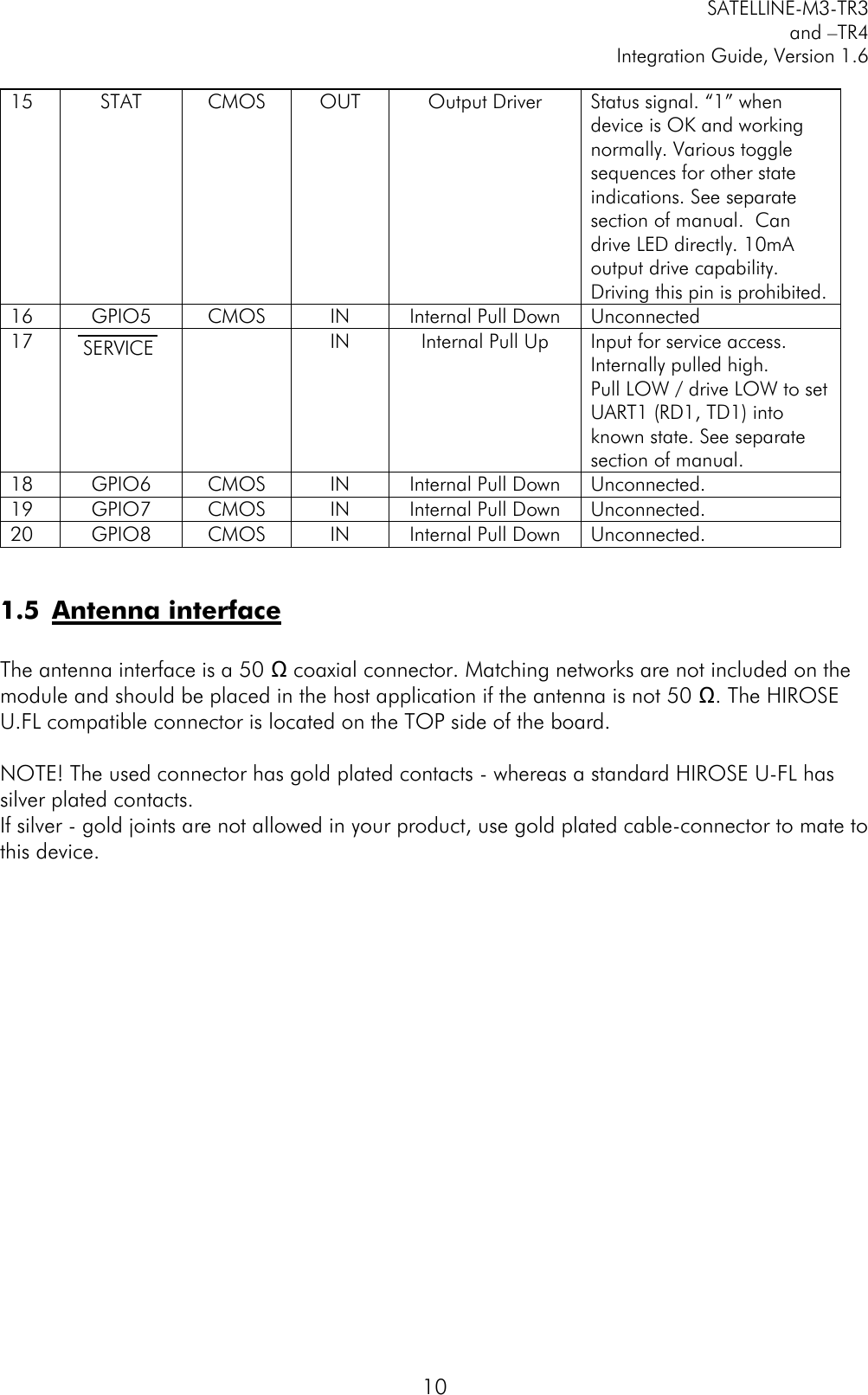
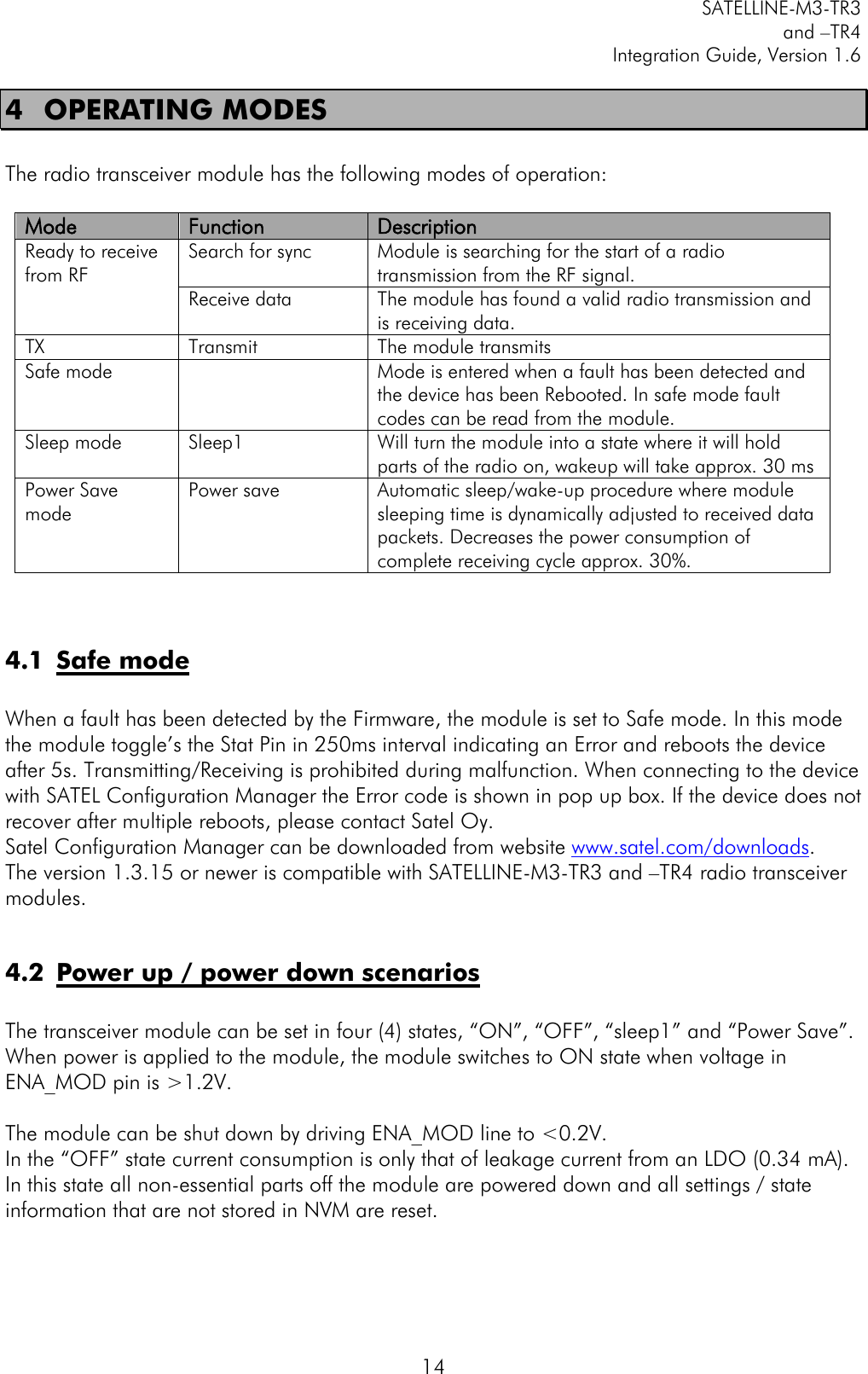
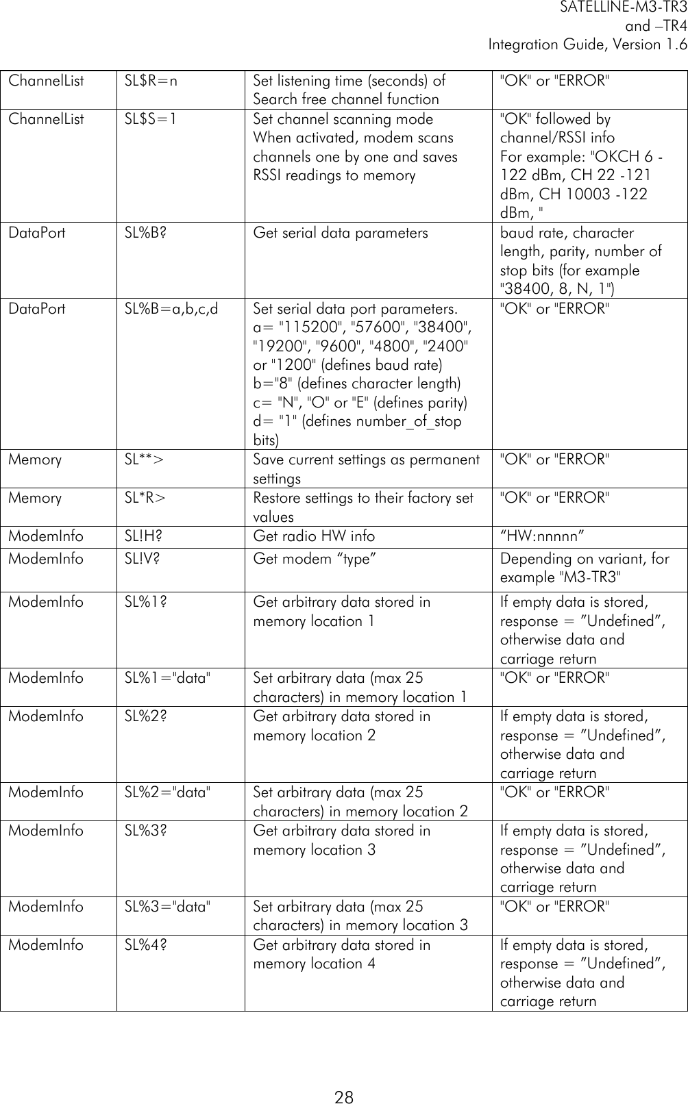
![SATELLINE-M3-TR3 and –TR4 Integration Guide, Version 1.6 31 RadioProperty SL@R? Get RSSI (Received Signal Strength Indication) of last received message (dBm) ”-nnn dBm”, nnn is a decimal value of field strength between –80 dBm and –118 dBm. Value is available 7 s after reception, after that the response is "<-118 dBm". SATELLINE-3AS Epic returns the stronger value of two transceivers. Radio Property SL@S? Get radio compatibility mode "0" = SATELLINE-3AS "1" = PacCrest-4FSK (Option1) "2" = PacCrest-GMSK (Option2) “3” = Trimtalk450s(P) (Option 3, RX fits PacCrest modems) “4” = Trimtalk450s(T) (Option 4, RX fits Trimble modems) "5" = PacCrest-FST (Option 5) RadioProperty SL@S=x Set radio compatibility mode. Value of x is: 0 = SATELLINE-3AS 1 = PacCrest-4FSK (Option1) 2 = PacCrest-GMSK (Option2) 3 = Trimtalk450s(P) (Option 3, RX fits PacCrest modems) 4 = Trimtalk450s(T) (Option 4, RX fits Trimble modems) 5 = PacCrest-FST (Option5) 20 = 8FSK FEC OFF (TR4 only) 21 = 8FSK FEC ON (TR4 only) 22 = 16FSK FEC ON (TR4 only) "OK" or "ERROR" Reset SL@X=n Reset command. Values of n are: "9" Reset modem "OK" or "ERROR", then modem resets required blocks. Test SL+P=xxxx Get measured signal strength from remote modem i.e. SL “ping” Value of xxxx [0000...ffff] defines address of remote modem "OK" followed by RSSI info from remote modem](https://usermanual.wiki/Satel/SATEL-TA23.10-SATELLINE-M3-TR3-TR4-V-1-6/User-Guide-2968788-Page-32.png)