Satel SATEL-TA23 SATEL-TA23 User Manual SATELLINE M3 TR3 V 1 2x
Satel Oy SATEL-TA23 SATELLINE M3 TR3 V 1 2x
Satel >
Contents
- 1. User Manual
- 2. User manual
- 3. 10 SATELLINE-M3-TR3_TR4_V_1_6
User Manual
SATELLINE-M3-TR3
TRANSCEIVER MODULE
INTEGRATION GUIDE
v.1.2

SATELLINE-M3-TR3
Integration Guide, Version 1.2
1
IMPORTANT NOTICE
All rights to this manual are owned solely by SATEL OY (referred to in this user guide as SATEL).
All rights reserved. The copying of this manual (without the written permission from the owner) by
printing, copying, recording or by any other means, or the full or partial translation of the manual
to any other language, including all programming languages, using any electrical, mechanical,
magnetic, optical, manual or other methods or devices is forbidden.
SATEL reserves the right to change the technical specifications or functions of its products, or to
discontinue the manufacture of any of its products or to discontinue the support of any of its
products, without any written announcement and urges its customers to ensure, that the
information at their disposal is valid.
SATEL software and programs are delivered ”as is”. The manufacturer does not grant any kind of
warranty including guarantees on suitability and applicability to a certain application. Under no
circumstances is the manufacturer or the developer of a program responsible for any possible
damages caused by the use of a program. The names of the programs as well as all copyrights
relating to the programs are the sole property of SATEL. Any transfer, licensing to a third party,
leasing, renting, transportation, copying, editing, translating, modifying into another
programming language or reverse engineering for any intent is forbidden without the written
consent of SATEL.
SATEL PRODUCTS HAVE NOT BEEN DESIGNED, INTENDED NOR INSPECTED TO
BE USED IN ANY LIFE SUPPORT RELATED DEVICE OR SYSTEM RELATED
FUNCTION NOR AS A PART OF ANY OTHER CRITICAL SYSTEM AND ARE
GRANTED NO FUNCTIONAL WARRANTY IF THEY ARE USED IN ANY OF THE
APPLICATIONS MENTIONED.
Salo, FINLAND 2014
Copyright: 2014 SATEL Oy
No part of this document may be reproduced, transmitted or stored in a retrieval system in any form or by any means
without the prior written permission of SATEL Oy. This document is provided in confidence and must not be distributed to
third parties without the express permission of SATEL Oy.

SATELLINE-M3-TR3
Integration Guide, Version 1.2
2
RESTRICTIONS ON USE
SATELLINE-M3-TR3 radio transceiver module has been designed to operate on 403-473
MHz, the exact use of which differs from one region and/or country to another. The user of a
radio transceiver module must take care that the said device is not operated without the
permission of the local authorities on frequencies other than those specifically reserved and
intended for use without a specific permit.
SATELLINE-M3-TR3 is allowed to be used in the following countries, either on license free
channels or on channels where the operation requires a license. More detailed information is
available at the local frequency management authority.
Countries: AT, BE, BG, CA, CH, CY, CZ, DE, DK, EE, ES, FI, FR, GB, GR, HU, IE, IS, IT, LT, LU,
LV, MT, NL, NO, PL, PT, RU, RO, SE, SI, SK, US
WARNING! Users of SATELLINE-M3-TR3 radio transceiver modules in North America should be aware,
that due to the allocation of the frequency band 406.0 – 406.1 MHz for government use only, the use of
radio transceiver module on this frequency band without a proper permit is strictly forbidden.
Host product labeling requirements
SATELLINE-M3-TR3 is intended to be integrated into a host device. Therefore the SATELLINE-M3-
TR3 product related FCC ID and IC ID must be visible in the host device chassis:
FCC ID: MRBSATEL-TA23
IC ID: 2422A-SATELTA23
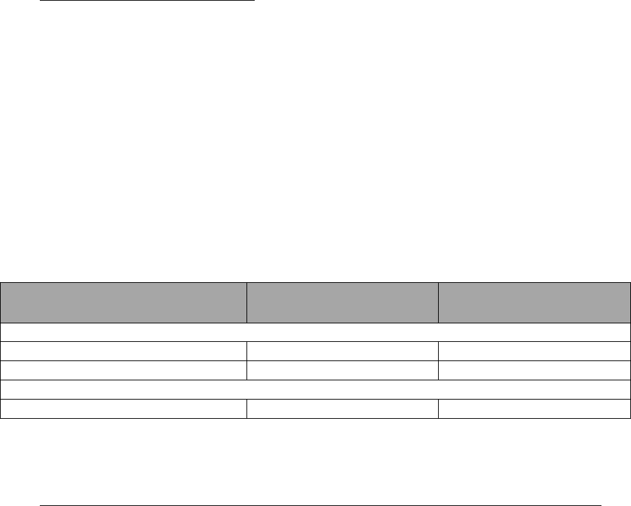
This integration guide applies to the combination of Firmware version/Hardware version listed in
the table below. See www.satel.com for the newest firmware and Integration Guide version.
Firmware version
Hardware version
Note!
07.22.2.0.2.4
SPL0020d,6
Since 12.08.2013
07.22.2.0.3.2
SPL0020d,7
01.10.2013
WARNING - RF Exposure
To comply with FCC and IC RF exposure compliance requirements, maximum antenna gain is
14 dBi and separation distance of at least 1 meter must be maintained between the antenna of
this device and all persons. This device must not be co-located or operating in conjunction with
any other antenna or transmitter.

SATELLINE-M3-TR3
Integration Guide, Version 1.2
3
PRODUCT CONFORMITY
Hereby, SATEL Oy declares that SATELLINE-M3-TR3 radio transceiver module is in compliance
with the essential requirements (radio performance, electromagnetic compatibility and electrical
safety) and other relevant provisions of Directive 1999/5/EC. Therefore the equipment is labeled
with the following CE-marking. The notification sign informs user that the operating frequency
range of the device is not harmonized throughout the market area, and the local spectrum
authority should be contacted before the usage of the radio module.

SATELLINE-M3-TR3
Integration Guide, Version 1.2
4
WARRANTY AND SAFETY INSTRUCTIONS
Read these safety instructions carefully before using the product:
-Warranty will be void, if the product is used in any way that is in contradiction with the
instructions given in this manual
-The radio transceiver module is only to be operated at frequencies allocated by local
authorities, and without exceeding the given maximum allowed output power ratings.
SATEL and its distributors are not responsible, if any products manufactured by it are used
in unlawful ways.
-The devices mentioned in this manual are to be used only according to the instructions
described in this manual. Faultless and safe operation of the devices can be guaranteed
only if the transport, storage, operation and handling of the device are appropriate. This
also applies to the maintenance of the products.

SATELLINE-M3-TR3
Integration Guide, Version 1.2
5
TABLE OF CONTENTS
IMPORTANT NOTICE ............................................................................................. 1!
RESTRICTIONS ON USE ......................................................................................... 2!
PRODUCT CONFORMITY ....................................................................................... 3!
WARRANTY AND SAFETY INSTRUCTIONS ............................................................. 4!
TABLE OF CONTENTS ............................................................................................ 5!
1!INTRODUCTION ............................................................................................... 7!
1.1!Terms and abbreviations ............................................................................. 7!
1.2!Description of the product ............................................................................ 7!
1.3!DTE connector ............................................................................................... 8!
1.4!Pin order of the DTE connector .................................................................... 9!
1.5!Antenna interface ...................................................................................... 10!
2!MECHANICAL CONSIDERATIONS .................................................................. 11!
2.1!Fixing device to host .................................................................................. 11!
2.2!Host board instructions for mounting pegs ............................................... 11!
3!CHANGING PARAMETERS USING SL COMMANDS ........................................ 12!
3.1!SL Commands ............................................................................................. 12!
3.2!SL Command Mode .................................................................................... 12!
4!OPERATING MODES ...................................................................................... 14!
4.1!Safe mode .................................................................................................. 14!
4.2!Power up / power down scenarios ............................................................. 14!
4.3!Sleep Mode ................................................................................................ 15!
SATELLINE-M3-TR3
Integration Guide, Version 1.2
6
4.4!Power Save Mode ....................................................................................... 15!
4.5!Restart ....................................................................................................... 16!
5!TIME PARAMETERS FOR STARTUP AND SHUTDOWN SEQUENCES ................ 17!
5.1!Startup sequence ....................................................................................... 18!
5.2!Shutdown sequence ................................................................................... 18!
5.3!Stat pin ....................................................................................................... 19!
5.4!Service pin .................................................................................................. 19!
6!TECHNICAL SPECIFICATIONS ......................................................................... 20!
6.1!Absolute maximum ratings (* .................................................................... 22!
6.2!DC electrical specifications ......................................................................... 22!
7!DEFAULT DELIVERY VALUES .......................................................................... 23!
8!CONSIDERATIONS ......................................................................................... 24!
8.1!EMI Interferers ........................................................................................... 24!
8.2!Electrostatic discharge ............................................................................... 25!
8.3!Using the device in unmanned high reliability applications .................... 25!
9!APPENDIX ...................................................................................................... 26!
9.1!SL COMMANDS ........................................................................................... 26!
10!VERSION HISTORY ....................................................................................... 32!
SATELLINE-M3-TR3
Integration Guide, Version 1.2
7
1
INTRODUCTION
SATEL OY is a Finnish electronics and Telecommunications Company specializing in the design
and manufacture of wireless data communication products. SATEL designs, manufactures and
sells radio modems intended for use in applications ranging from data transfer to alarm relay
systems. End users of SATEL products include both public organizations and private individuals.
SATEL OY is the leading European manufacturer of radio modems. SATEL radio modems have
been certified in most European countries and also in many non-European countries.
This document is the integration guide for the SATELLINE-M3-TR3 radio transceiver module. It is
intended to describe how to use the module and how to integrate it into a host device.
1.1
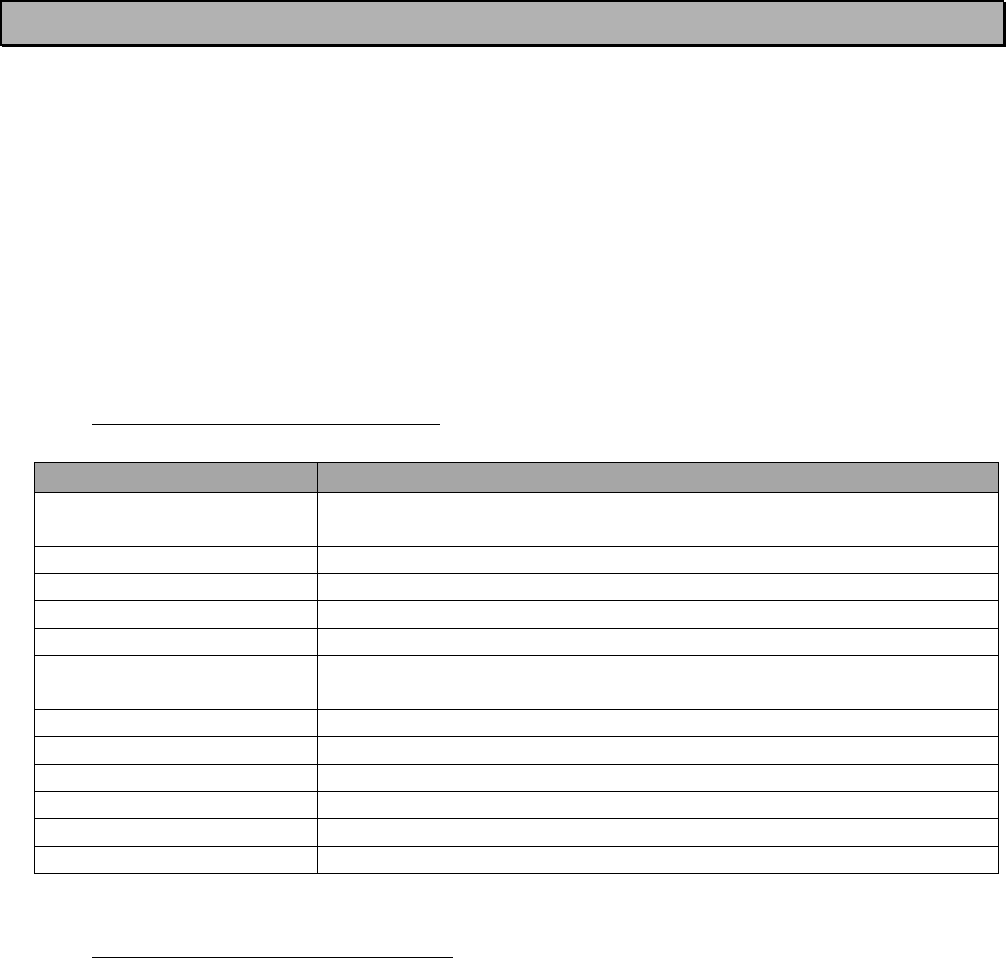
Terms and abbreviations
Abbreviation
Description
CTS
Clear To Send, handshaking signal used in asynchronous
communication.
DTE
Data Terminal Equipment (typically computer, terminal…)
ESD
Electrostatic discharge
RD
Receive Data
TD
Transmit Data
RTS
Ready To Send, handshaking signal used in asynchronous
communication.
RAM
Random Access Memory
LDO
Low dropout regulator
UHF
Ultra High Frequency
RF
Radio Frequency
FPGA
Field-programmable gate array
CPU
Central processing unit
1.2
Description of the product
The SATELLINE-M3-TR3 is a UHF radio transceiver module, which transmits and receives data
from UHF transmissions made by SATELLINE-3AS family and similar transmitters.
The module is designed to be as compact and power efficient as possible. It has been developed
to be especially suitable for integration into battery powered and space constrained host
applications benefiting from UHF communications.
The module transmits and receives data via the Air interface (Ant. Connector, RF), modulates and
demodulates, encodes and decodes the data and sends the received data payload to the DTE
port. The DTE interface is used to provide power to the module and communicate with the
module.
SATELLINE-M3-TR3
Integration Guide, Version 1.2
8
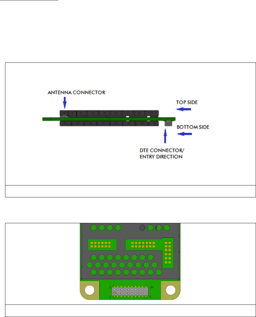
1.3
DTE connector
The DTE connector is a 20-pin pass-through connector. This connector allows the pin to enter the
connector from the bottom side and protrude thru the module PCB to the top side, allowing
flexible mounting heights with various pin lengths.
Entry from bottom of device, see picture below.
Figure 1. Side view of the module with 1.27mm pitch connector and screw fixing.
Figure 2. Pin numbering of 1.27 mm pitch DTE connector. View from bottom side of unit.

SATELLINE-M3-TR3
Integration Guide, Version 1.2
9
1.4
Pin order of the DTE connector
Direction IN is data from DTE (Data Terminal Equipment) to the radio transceiver module.
Direction OUT is data from the radio module to the DTE.
Pin
No.
Signal
name
Type
Direction
Pin State
Description
1,2
VCC_IN
POWER
IN
External Voltage
4.0V DC input
3,4
GND
GND
-
External Ground
Ground reference for power
and signals
5
VCC_IO
POWER
IN
External Voltage
Device IO driver input DC
voltage.
Voltage= 1.8 … 3.3 V
6
ENA_MOD
IO
IN
Internal Pull Down
Enable module by pulling
HIGH.
>1.2 V= Module power is
ON,
<0.2 V= Module power is
OFF
7
RD1
CMOS
OUT
Output Driver
Receive data.
Data received by module is
output on this pin. Driving
this pin is prohibited.
8
CTS1
CMOS
OUT
Output Driver
Clear To Send.
Module signals when it is
ready to receive data.
Driving this pin is prohibited.
9
TD1
CMOS
IN
Internal Pull Up
Transmit Data.
Data from DTE to module
shall be sent on this pin. Pull
LOW or drive LOW or
HIGH.
10
RTS1
CMOS
IN
Internal Pull Up
Ready to send.
DTE can use this pin to
signal when it is ready to
receive data from module.
Pull LOW or drive LOW or
HIGH.
11
GPIO1
CMOS
IN
Internal Pull Down
Unconnected.
12
GPIO2
CMOS
IN
Internal Pull Down
13
GPIO3
CMOS
IN
Internal Pull Down
14
GPIO4
CMOS
IN
Internal Pull Down

SATELLINE-M3-TR3
Integration Guide, Version 1.2
10
1.5
Antenna interface
The antenna interface is a 50 Ω coaxial connector. Matching networks are not included on the
module and should be placed in the host application if the antenna is not 50 Ω. The HIROSE
U.FL compatible connector is located on the TOP side of the board.
NOTE! The used connector has gold plated contacts - whereas a standard HIROSE U-FL has
silver plated contacts.
If silver - gold joints are not allowed in your product, use gold plated cable-connector to mate to
this device.
15
STAT
CMOS
OUT
Output Driver
Status signal. “1” when
device is OK and working
normally. Various toggle
sequences for other state
indications. See separate
section of manual. Can
drive LED directly. 10mA
output drive capability.
Driving this pin is prohibited.
16
GPIO5
CMOS
IN
Internal Pull Down
Unconnected
17
SERVICE
IN
Internal Pull Up
Input for service access.
Internally pulled high.
Pull LOW / drive LOW to set
UART1 (RD1, TD1) into
known state. See separate
section of manual.
18
GPIO6
CMOS
IN
Internal Pull Down
Unconnected.
19
GPIO7
CMOS
IN
Internal Pull Down
Unconnected.
20
GPIO8
CMOS
IN
Internal Pull Down
Unconnected.
SATELLINE-M3-TR3
Integration Guide, Version 1.2
11
2
MECHANICAL CONSIDERATIONS
2.1
Fixing device to host
The radio transceiver module can be mounted on to the host by using spacers and screws. Max.
screw diameter is 3mm.
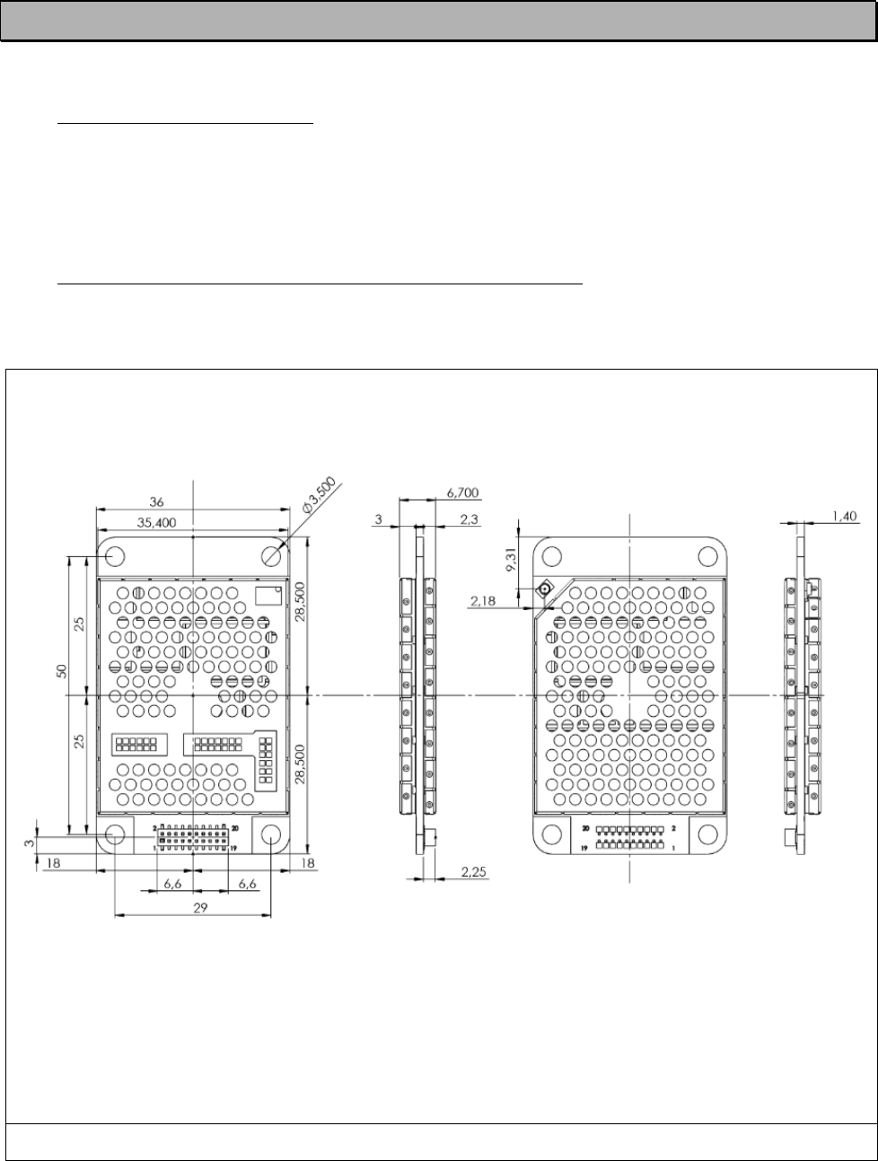
2.2
Host board instructions for mounting pegs
In figure below is SATELLINE-M3-TR3 with dimensions as millimeters.
Figure 3. The physical dimensions and the holes in millimeters.
SATELLINE-M3-TR3
Integration Guide, Version 1.2
12
3
CHANGING PARAMETERS USING SL COMMANDS
The controlling terminal device can change the configuration settings of the module. This is
accomplished with the help of SL commands. SL commands can be used to change e.g. the
frequency or addresses. It is also possible to ask the radio transceiver module to show current
settings which are in use.
3.1
SL Commands
An SL command is a continuous string of characters, which is separated from other data by
pauses which are equal or greater than time defined by Pause length parameter (default=3
characters) in the set-up. No extra characters are allowed at the end of an SL command.
Serial interface settings are the same as in data transfer. SL command is properly recognised also
in the case when the command string is terminated by <CR> (=ASCII character no. 13,
Carriage Return, 0x0d) or <CR><LF> (<LF> = ASCII char. no. 10, Line Feed, 0x0a). If
multiple SL commands are sent to the module, the next command can be given after receiving
the response ("Ok" or "Error") of the proceeding command. In addition, it is recommended to
implement a timeout to the terminal software for recovering the case when no response is
received from the radio module.
The transceiver module will acknowledge all commands by returning an "OK" (command carried
out or accepted) or the requested value, or an "ERROR" (command not carried out or
interpreted as erroneous) message.
The SL commands are listed in appendix, pages 26.
3.2
SL Command Mode
The SL commands have always been enabled in the previous products like M3-R3. When the SL
commands are enabled there are possibilities that the user data may start with the characters
“SL” which is handled as the SL command. This has caused the firmware to go to the continuous
SL command search mode and any data has not been sent or even an “ERROR”
acknowledgment has been received. To avoid this kind behavior the user can disable the SL
commands. The SL commands can be disabled or enabled using the “SL Command mode”
parameter. The user can do this via the SATEL Configuration Manager, version v1.3.15 or newer.
By default the SL Command mode is set to ON. If the SL Command mode is set to OFF then the
SL commands can be enabled or disabled using the following procedures:

SATELLINE-M3-TR3
Integration Guide, Version 1.2
13
To enable the SL Commands:
• Send three “+” characters via serial port so that there is at least three bytes delay
between each character. The response is “OK”, when successfully set.
<+><at least three bytes pause><+><at least three bytes pause><+>
To disable the SL Commands:
• Send three “-” characters via serial port so that there is at least three bytes delay between
each character. The response is “OK”, when successfully set.
<-><at least three bytes pause><-><at least three bytes pause><->
Note!
The “+ + +” and “- - -” procedures are not allowed to be used, when radio is transmitting or
receiving data (i.e. the application data occupies the TD or RD lines of the radio).
SATELLINE-M3-TR3
Integration Guide, Version 1.2
14
4
OPERATING MODES
The radio transceiver module has the following modes of operation:
Mode
Function
Description
Ready to receive
from RF
Search for sync
Module is searching for the start of a radio
transmission from the RF signal.
Receive data
The module has found a valid radio transmission and
is receiving data.
TX
Transmit
The module transmits
Safe mode
Mode is entered when a fault has been detected and
the device has been Rebooted. In safe mode fault
codes can be read from the module.
Sleep mode
Sleep1
Will turn the module into a state where it will hold
parts of the radio on, wakeup will take approx. 30 ms
Power Save
mode
Power save
Automatic sleep/wake-up procedure where module
sleeping time is dynamically adjusted to received data
packets. Decreases the power consumption of
complete receiving cycle approx. 30%.
4.1
Safe mode
When a fault has been detected by the Firmware, the module is set to Safe mode. In this mode
the module toggle’s the Stat Pin in 250ms interval indicating an Error and reboots the device
after 5s. Transmitting/Receiving is prohibited during malfunction. When connecting to the device
with SATEL Configuration Manager the Error code is shown in pop up box. If the device does not
recover after multiple reboots, please contact SATEL Oy.
SATEL Configuration Manager can be downloaded from website www.satel.com/downloads.
The version 1.3.15 or newer is compatible with SATELLINE-M3-TR3 radio transceiver module.
4.2
Power up / power down scenarios
The transceiver module can be set in four (4) states, “ON”, “OFF”, “sleep1” and “Power Save”.
When power is applied to the module, the module switches to ON state when voltage in
ENA_MOD pin is >1.2V.
The module can be shut down by driving ENA_MOD line to <0.2V.
In the “OFF” state current consumption is only that of leakage current from an LDO (0.34 mA).
In this state all non-essential parts off the module are powered down and all settings / state
information that are not stored in NVM are reset.

SATELLINE-M3-TR3
Integration Guide, Version 1.2
15
4.3
Sleep Mode
When being in sleep mode, the radio part of the module is switched off while the serial interface
communication related parts remain powered on. The module will be automatically woken up
after the CPU senses a state change in the TD1 pin. Example: The module is in Sleep1- mode.
The module is woken up by sending a character or characters into the TD1 pin after which the
module responses “OK”. After “OK” the module is ready for normal communication.
To turn the module ON from sleep1 mode:
1) Issue a state change to TD1 (toggle pin (minimum pulse duration time 10 µs) or issue a
byte on the UART (for example 0x00))
2) Wait for “OK” -response from the module. The wake-up time is approx. 30 ms.
3) Start communicating normally
Module will remain powered ON until a new sleep command is issued.
4.4
Power Save Mode
The Power save mode performs an automatic, self-adjusting receiver wake-up/sleep cycle.
It is designed for applications which base on one-way communication with relatively constant TX
interval and, in which the data packet separation is > 200 ms.
When enabled, the unit makes the transmission interval study basing on four (4) successfully
received data packets. The shortest time between transmitted packets is measured (tmin).
Measured value is updated after each successfully received data packet, so that possible
changes in the message length becomes noted.
Ensuring that the complete messages will be received even if there occur little variation in
transmission interval, some safety margin (tmarg) is left into Ready to receive from RF mode time.
Safety margin is calculated by dividing the shortest time between transmitted packets (tmin, in ms)
with 8 and by adding 60 ms to this result:
tmin8+ 60 ms
The length of the whole sleeping period (tsleep) is calculated by decreasing the shortest time
between transmitted packets (tmin) with safety margin (tmarg) and transmission time of the original
message (tTX):
tsleep= tmin − tmarg − tTX
SATELLINE-M3-TR3
Integration Guide, Version 1.2
16
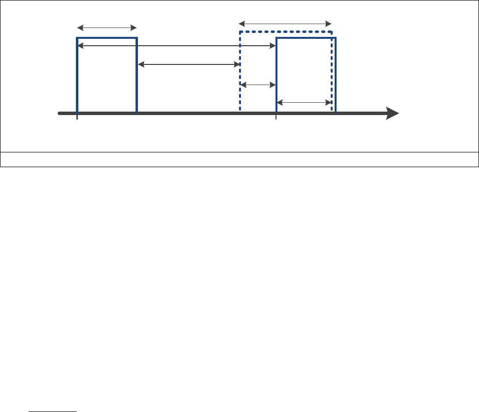
Transmission interval study is started over always after 100 successful sleep/wake-up cycles and,
if the expected receiving slot (tRX slot) with enhanced overlap margin (toverlap) has been missed. In
latter case the package is considered to be lost.
toverlap = tmarg + 100 ms
tRX slot, min = tmin - tmarg
tRX slot, max = tmin + toverlap
tTX
tmin
tRX(slot
t
0
tsleep
toverlap
tmarg
Figure 4. Power save mode timing factors.
E.g. In system with TX interval of 1 s, and with 300 ms (approx. 300B @ 9600 bps) transmission
time:
tmin = 1000 ms
tTX =300 ms
tmarg =125 ms + 60 ms = 185 ms
tsleep= 1000 ms − (125 ms + 60 ms) − 300 ms = 515 ms
tRX slot, min = 1000 ms – 185 ms = 815 ms
tRX slot, max = 1000 ms + 285 ms = 1285 ms
4.5
Restart
After startup the module can be restarted by issuing a SL command, upon which the module will
shut down all circuitry, and Reboot the CPU (see SL-list).

SATELLINE-M3-TR3
Integration Guide, Version 1.2
17
5
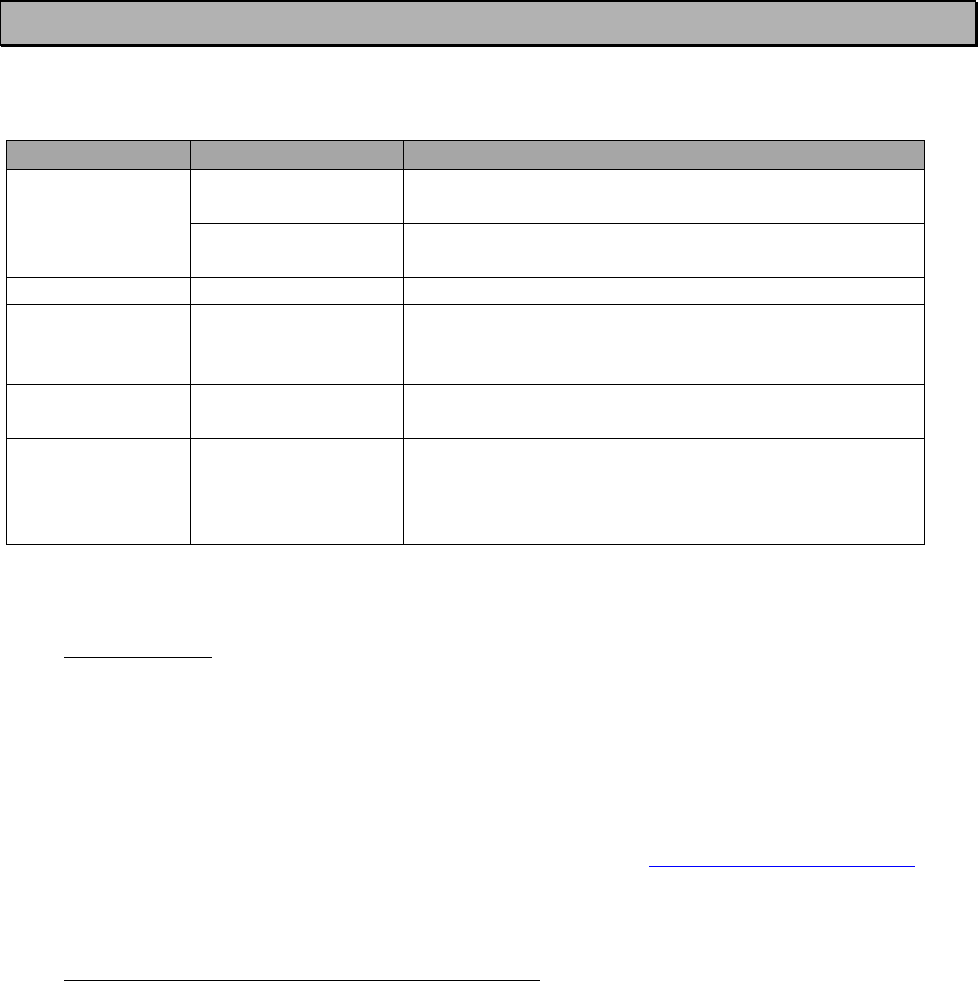
TIME PARAMETERS FOR STARTUP AND SHUTDOWN
SEQUENCES
Parameter
Recom. Time (*
Explanation
Tvic
Input capacitor
charge time
>50µs
When voltage is applied to VCC_IN the filter
capacitors inside the module are charged,
creating a small current surge. If the feeding
power supply is not very strong it is
recommended to wait this time before rising
ENA_MOD to minimize current surge.
Tioen
IO module start
time
<18ms
ENA_MOD enables the LDOs feeding the
FPGA and CPU inside the module. It is
recommended to apply VCC_IO voltage
within 18ms after ENA_MOD is applied.
Tiovs
IO voltage
startup time
<1ms
It is considered good design practice to KEEP
all IO signals (except ENA_MOD) low or
floating until the internal parts of the module
have power and the IO voltage is stable.
Tior
IO drive fall
time
< 300 µs
It is considered good design practice to set all
IO signals (except ENA_MOD) low or floating
before starting to shut down the transceiver
module. This way any latch up/brownout
problems can be avoided. IO-pins are not
internally driven after Tior.
Tldof
LDO discharge
time
> 300 µs
To avoid any possibility of reverse biasing of
regulators inside the module, it is considered
good design practice to use ENA_MOD to
shut down the regulators before deactivating
VCC_IN.
Table. Startup and shutdown sequence parameters.
*) Recommendations:
The radio module is designed and tested for the minimum times mentioned in the table. The
recommendations are there for those who want to do the very best possible startup and shutdown
sequences.
SATELLINE-M3-TR3
Integration Guide, Version 1.2
18
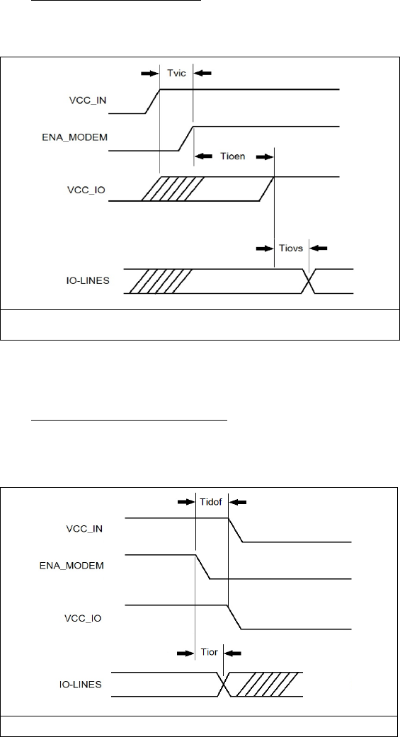
5.1
Startup sequence
The following diagram will describe the startup sequence.
Figure 7. Startup sequence.
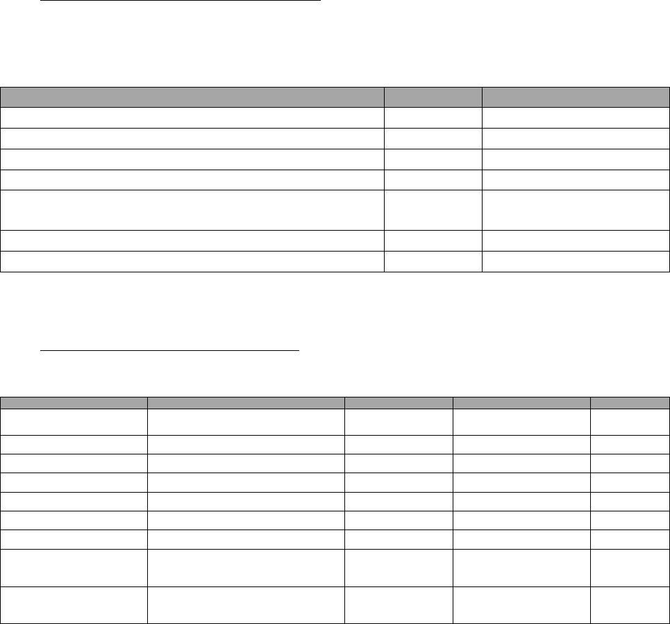
5.2
Shutdown sequence
The following diagram will describe the shutdown sequence.
Figure 8. Shutdown sequence.

SATELLINE-M3-TR3
Integration Guide, Version 1.2
19
5.3
Stat pin
The STAT pin indicates the status of the device. It can be used to drive a LED using a series
resistor. STAT pin drive capability is 10mA (loads the VCC_IO).
The STAT pin has the following behavior.
Blink cycle
Mode
“1” - statically
module is operational “searching for a new frame”
“0” for the endurance of the
received frame.
“0” when module is receiving data from air interface.
In practical cases will toggle at the frequency of the data
packets on the air interface.
“0” statically
Module is in sleep1 mode
The pin is toggled in transmission
interval
Module is sending data Over the Air
Pin is toggled in 1s interval
Module has the connection to Configuration Manager
program.
Pin is toggled in 500ms interval
SL Command mode.
Pin is toggled in 250ms interval
Module has detected a fault, fault codes can be read via
Configuration Manager program.
Table. Modes of STAT pin.
5.4
Service pin
The SERVICE pin is used to set the UART1 into a known state. Pulling this pin low will activate the
service mode and set the UART1 into 38400, n, 8, 1. This is intended for service access of the
module, to have a known serial port setting in order to access the module settings.
The pin does not affect any permanent settings, nor does it change the mode of the module.
Releasing/ driving the pin high will return serial port 1 into the configured state.
When service pin is used the SL Commands are forced to be ON although they are OFF in
settings.

SATELLINE-M3-TR3
Integration Guide, Version 1.2
20
6
TECHNICAL SPECIFICATIONS
SATELLINE-M3-TR3 complies with the following international standards:
EN 300 113-2, ANNEX A EN 301 489-1
EN 60950-1 FCC CFR47 PART 90
RECEIVER
TRANSMITTER
Note!
Frequency Range
403...473 MHz
Tuning range
70 MHz
Minimum RF Frequency
Step
6.25 kHz
Channel Bandwidth
12.5 kHz / 25 kHz
Programmable
Frequency Stability
<1 kHz
Maximum Receiver Input
Power without Damage
+14 dBm
Maximum Receiver Input
Power without Transmission
Errors
-10 dBm
FEC ON
Sensitivity 1,2
-113 dBm @ 25 kHz
-116 dBm @ 12.5
kHz
FEC ON
Blocking 1,2
> 86 dB @ 25 kHz
> 88 dB @ 12.5 kHz
FEC ON
Intermodulation
Attenuation 1,2
> 61 dB @ 25 kHz
> 61 @ 12.5 kHz
FEC ON
CO-Channel Rejection 1,2
> -11 dB @ 25 kHz
> -10 dB @ 12.5 kHz
FEC ON
Adjacent Channel
Selectivity 1,2
> 56 dB @ 25 kHz
> 51 dB @ 12.5 kHz
FEC ON
Spurious Rejection
> 67 dB
FEC ON
Typical Power
Consumption
730 mW
RX-mode
SLEEP1: 215 mW
RX-mode
4.7 W @ 1 W RF out
TX-mode,
Continuous, 50Ω
3.3 W @ 500 mW RF
out
TX-mode,
Continuous, 50Ω
2.8 W @ 100 mW RF
out
TX-mode,
Continuous, 50Ω
2.6 W @ 100 mW RF
out
TX-mode,
Continuous, 50Ω
Transmitter Power
(programmable)
100 mW, 200 mW, 500
mW, 1 W
TX-mode, 50Ω
load
Communication Mode
Half-Duplex
Adjacent Channel Power
acc. to EN 300 113-
1v.1.7.1
TX-mode

SATELLINE-M3-TR3
Integration Guide, Version 1.2
21
Transient Adjacent
Channel Power
acc. to EN 300 113-
1v.1.7.1
TX-mode
Carrier power stability
< ±1.5 dB
DATA MODULE
Timing
UART
Electrical Interface
CMOS Inputs and outputs referred to IO
Voltage processed by user (1.8-3.3V) RTS,
CTS, RX, TX,
+VCC, GND
Interface Connector
1.27 mm pitch socket
Samtec 20-pin through
hole, CLP-110-02-L-D-K-
TR
Data speed of Serial
interface
1200 – 115200 bps
Data speed of Radio Air
Interface
19200 bps (25 kHz channel bandwidth)
9600 bps (12.5 kHz channel bandwidth)
Air Interface Encryption
AES128
Programmable
Data Format
Asynchronous data
Modulation
4FSK, GMSK
GENERAL
Operating voltage
+4.0 VDC
min. 5 4.0V, max. Nominal
+5%
Maximum DC Ripple
Voltage 3
max. 9 mVpp
DC ≤ f ≤ 1 kHz
max. 64 mVpp
1 kHz < f ≤ 10 kHz
mx. 517 mVpp
10 kHz < f ≤ 100 kHz
max. 2.035 Vpp
f > 100 kHz
Inrush Current, power
turned ON 4
< 12A, duration < 50 µs
RX-mode
Inrush Current, from RX to
TX 4
not detected
TX output power 1W
< 150 mA, duration < 1 ms
TX output power 500 mW
< 70 mA, duration < 1 ms
TX output power 200 mW
< 30 mA, duration < 1 ms
TX output power 100 mW
Temperature Range
-20°C … +55°C
Type Approval conditions
Temperature Ranges
-30°C … +70°C
Functional
-40°C … + 80°C
Storage
Vibration 6
≤10g
100Hz≤fvibration≤1,0 kHz
ESD
±10 kV
Antenna connector. Acc. to
EN61000-4-2;
150pF/330Ω
±8 kV
DTE connector. Acc. to
EN61000-4-2;
150pF/330Ω
Antenna Connector
50Ω, HIROSE U.FL compatible
I-PEX 20279-001 -E-01
Construction
PWB with sheet metal EMI shields
Size L x W x T
57 x 36 x 6.7 mm
Weight
18g
Test condition !
!! = 4.0 V and !
! = 25 °C
SATELLINE-M3-TR3
Integration Guide, Version 1.2
22
1 According to EN 300 113-1 V.1.7.1 measurement setup
2 The measured average of a sample of 19 M3-TR3 modules
3 Higher values exceed the -36 dBm spurious limit at the antenna e.g. EN 300 113-1 requirement.
4 Measured using Agilent 1147B current probe and TTi TSX1820P DC power supply
5 If 1 W output power is wanted then 4.0 V is the minimum DC voltage
6 Functional operation is guaranteed in all directions xyz
6.1
Absolute maximum ratings (*
Absolute maximum ratings for voltages on different pins are listed in the following table.
Exceeding these values will cause permanent damage to the module.
Parameter
Min
Max
Voltage at VCC_IN
-0.3 V
+5 V
Voltage at ENA_MOD
-0.3 V
+6 V
Voltage at VCC_IO
-0.5 V
3.75 V
Voltage at digital inputs (except ENA_MOD)
-0.5 V
3.75 V
Voltage at digital outputs (when no power is
applied to unit)
-0.5 V
3.75 V
Antenna port power
n.a.
+14 dBm
Antenna port DC voltage
-10V
+10V
Table. Absolute maximum ratings of module. (* All voltages are referenced to GND
6.2
DC electrical specifications
Over recommended operating conditions
Parameter
Condition
Min
Max
Units
VCC_IN
4.0V is considered nominal
4.0V 1
Nominal +5%
V
ENA_modem, Vlow
0.9
VCC_IN
V
ENA_modem, Vhigh
0
0.4
V
Logic input, Vlow
1.8V<VCC_IO<3.3V
-0.3
<0.35*VCC_IO
V
Logic input, Vhigh
1.8V<VCC_IO<3.3V
0.65*VCC_IO
3.6
V
Logic output, Vlow
1.8V<VCC_IO<3.3V
-
0.4
V
Logic output, Vhigh
1.8V<VCC_IO<3.3V
VCC_IO-0.4
3.6
V
Logic output, max
current
All logic output except
STAT pin.
-
4
mA
Logic output, max
current, STAT pin
-
12
mA
1 Minimum voltage if the maximum TX output power (1W/50 Ω load) is wanted. Meets the ETSI
requirements on given operating voltage range.

SATELLINE-M3-TR3
Integration Guide, Version 1.2
23
7
DEFAULT DELIVERY VALUES
DEFAULT VALUES OF THE ADJUSTABLE SETTINGS (the user can change these
settings later on)
Setting
Default value
Range
Radio frequency
Operating TX and RX
frequency
438.000 MHz
403 - 473 MHz
Channel Spacing
12.5 kHz
12.5 kHz or 25 kHz
Transmitter Output Power
1 W
100 mW, 200 mW, 500 mW and 1 W
Radio settings
Radio Compatibility
SATEL 3AS
SATEL 3AS
PacCrest-4FSK
PacCrest-GMSK
PacCrest-FST
TrimTalk450s(P)
TrimTalk450s(T)
Addressing
RX Address
OFF
ON/OFF
TX Address
OFF
ON/OFF
Serial port
Data speed
115200 bps
1200 -115200 bps
Data bits
8
8
Parity bits
None
None, Even, Odd
Stop bits
1
1
Handshaking
Handshaking lines apply to the DATA-
port
CTS
TX Buffer State
Clear to send, TX Buffer State
RTS
Ignored
Ignored, Flow Control
Additional setup
Error Correction, FEC
OFF
ON/OFF
Error check
OFF
OFF, CRC8Partial, CRC8Full,
CRC16Full
SL Command Mode
ON
ON/OFF
Repeater Mode
OFF
ON/OFF
TX Delay
0
0 …. 65535 ms
Over-the-Air-Encryption
OFF
ON/OFF
Use Channel List
OFF
ON/OFF
Power Save Mode
OFF
ON/OFF
Add RSSI to Data
OFF
ON/OFF

SATELLINE-M3-TR3
Integration Guide, Version 1.2
24
8
CONSIDERATIONS
8.1
EMI Interferers
The module is designed to be mounted inside a host device. The module is designed to
withstand EMI even beyond type approval requirements. However, a small module which is
integrated closely to modern high speed electronics is bound to receive some interference.
To make a working integration, consider the following: EMI can enter the module in four ways:
1) Via the antenna (radiation from enclosure enters the antenna)
2) Radiated disturbances to the coaxial cable
3) Radiation from other electronics / cabling directly to the module
4) Conducting through the DTE interface (power, control and data lines).
Because the module is shielded and the DTE interface is filtered, the usually worst method of
disturbance is via the antenna port, which is easily overlooked in design. Keep in mind that the
radio module has a sensitivity of approx. -115 dBm (depends on mode of operation and speed
etc.). While the module has an approx. 10 dB S/N requirement, this constitutes, that any signal
entering the radio antenna on receive frequency on a level of < -125 dBm (-115dBm-10dB),
causes desensitization of the radio on that particular channel.
Example:
An interferer has a level of -100dBm on the frequency 421 MHz. The radio will show an
approximate sensitivity of -90dB (-100dBm+S/N requirement 10 dB) on 421 MHz.
Now consider that generic EMC requirements usually have pass/fail criteria of -57dBm (if
normalized to the surface of the device). So there is almost a 70dB gap between
generic EMC requirements and co-existence requirements between a high
sensitivity narrowband radios.
To avoid problems of co-existence a good design should apply:
1) EMI shielding in enclosure – ambient air interface
2) careful layout
3) shielding of all digital high speed parts and cables
4) Have a clocking plan to avoid clock frequencies causing harmonics on
the UHF band of interest.
Number one is to recognize this challenge and act upon it.
SATEL R&D can help in this by participating in design review of the host device, aiming to catch
problems early in the design phase.
SATELLINE-M3-TR3
Integration Guide, Version 1.2
25
8.2
Electrostatic discharge
As the module is intended to be embedded in a host application, in a typical use case, the
antenna port is the only port of the module directly interface with a surface or contact area
subjected to Electrostatic Discharge (ESD).
Thus, the antenna port is the only interface with high level ESD protection. The DTE port also
features ESD protection diodes, but is not designed to withstand similar performance as expected
from standalone units with enclosures.
Consequently, the module should be subject to ESD handling precautions that typically apply to
ESD sensitive components. Proper ESD handling and packaging procedures must be applied
throughout the processing, handling and operation of any application that incorporates this
module.
The module fulfills the ESD values listed in the following table.
Specification /
Requirement
Contact discharge
Air discharge
EN 61000-4-2
Antenna interface
±10kV
<±15kV
DTE interface
±8kV
-
JEDEC JESD22-A114D (Human Body Model, Test conditions: 1.5 kΩ, 100 pF)
Module surface
±1kV
n.a.
Table. ESD ratings. Measured Acc. to EN 61000-4-2 specification.
8.3
Using the device in unmanned high reliability applications
The module features software and hardware watchdogs which are incorporated inside the CPU.
While we believe that this is a reliable method of keeping the module in operational condition,
there are parts of the module that can’t be monitored for proper operation to 100%. For example
the module chip has a firmware that resides in the chips RAM. The firmware can’t be read back
or reloaded, without interrupting reception. Hence the module can’t reload this automatically by
itself without causing breaks in communication.
To avoid the module from ending up in a state where for example the module chip firmware is
corrupted for example by ionizing radiation, it is recommended that the controlling system
implements some form of watchdog function for the module.
This can be done for example if the system knows that data should be received every second,
and no data has been received for a minute – then do a module restart using the ENA_MOD pin
or by issuing a restart command, or a cold boot by toggling VCC_IN low and high again.

SATELLINE-M3-TR3
Integration Guide, Version 1.2
26
9
APPENDIX
9.1
SL COMMANDS
Category
Command
Description
Response
Addressing
SL#A?
Show all addresses (RX1, RX2, TX1,
TX2)
"xxxx,yyyy,zzzz,vvvv"
Addressing
SL#A=xxxx, yyyy,
zzzz,vvvv
Set RX/TX addresses (RX1, RX2,
TX1, TX2)
"OK" or "ERROR"
Addressing
SL#I?
Get primary addresses (TX1, RX1)
"xxxx;yyyy"
Addressing
SL#I=xxxx
Set all addresses (RX1, RX2, TX1,
TX2) to value xxxx [0000....ffff]
"OK" or "ERROR"
Addressing
SL#P?
Get primary transmit address (TX1)
and primary receive address (RX1)
"xxxx;yyyy"
Addressing
SL#P=xxxx;yyyy
Set primary transmit address (TX1)
to value xxxx and primary receive
address (RX1) to value yyyy
[0000....ffff]
"OK" or "ERROR"
Addressing
SL#Q?
Get TX address mode
"0" = TX address OFF
"1" = TX address ON
Addressing
SL#Q=x
Set TX address ON/OFF. Values of
x are:
"0" = TX address OFF
"1" = TX address ON
"OK" or "ERROR"
Addressing
SL#R?
Get primary receive address (RX1)
"yyyy"
Addressing
SL#R=xxxx
Set receive addresses (RX1, RX2) to
value xxxx [0000....ffff]
"OK" or "ERROR"
Addressing
SL#S?
Get secondary transmit address
(TX2) and secondary receive
address (RX2)
"xxxx;yyyy"
Addressing
SL#S=xxxx;yyyy
Set secondary transmit address
(TX2) to value xxxx and secondary
receive address (RX2) to value yyyy
[0000....ffff]
"OK" or "ERROR"
Addressing
SL#T?
Get primary transmit address (TX1)
"xxxx"
Addressing
SL#T=xxxx
Set transmit addresses (TX1, TX2) to
value xxxx [0000....ffff]
"OK" or "ERROR"
Addressing
SL#W?
Get RX address mode
"0" = RX address OFF
"1" = RX address ON
Addressing
SL#W=x
Set RX address ON/OFF. Values of
x are:
"0" = RX address OFF
"1" = RX address ON
"OK" or "ERROR"
ChannelList
SL$A=1
Go to channel list default channel
"OK" or "ERROR"

SATELLINE-M3-TR3
Integration Guide, Version 1.2
27
ChannelList
SL$C?
Get number of channels in channel
list
decimal number
ChannelList
SL$C=nn
Set number of channels in channel
list. nn = 0...40, 0 clears the whole
list
"OK" or "ERROR"
ChannelList
SL$D?
Get channel list default channel
number
decimal number
ChannelList
SL$D=n
Set channel list default channel, n is
channel number
"OK" or "ERROR"
ChannelList
SL$E=1
Search free channel
Modem searches for next traffic-free
channel. Listening time of traffic is
about 2 seconds
Modem shows next free channel by
activating command again
"OK" followed by “channel
n is free”
Value of n is channel
number of next free channel
on channel list
ChannelList
SL$F?
Get active channel number
decimal number
ChannelList
SL$F=n
Set modem to channel number n in
channel list
"OK" or "ERROR"
ChannelList
SL$L?nn
Get channel info.
Index nn=[0...(number of channels-
1)]
Channel number,
Frequency, Channel width,
Tx Power
For example: "CH 1,
430.150000 MHz, 25.0
kHz, 100 mW\0D"
ChannelList
SL$L=Iaa,Nbbbb
bb,Fccc.cccccc,W
dd.ddd,Peeeee<
CR>
I = Index field aa = 0...39 //Future
reservation 0...255
N = Channel number field bbbbbb
= -32767...32767
F = Tx/Rx Frequency field
ccc.cccccc = Tx/Rx Frequency in
MHz (only numbers or "." allowed,
"," is not allowed)
W = Channel spacing/width field
ddddd = 12.5, 20 or 25 (unit is
kHz, trailing decimals are tolerated
e.g. "25", "25.0", "25.00" and
"25.000" are all valid)
P = Transmitter power field eeeee
= 0...35000 (modem rounds the
value to the closest applicable)
Note: 0 means "don't care" value for
power.
<CR> = Carriage return character
"OK" or "ERROR"
ChannelList
SL$M?
Get status of channel list. 0 = Not
in use, 1 = Channel list in use
"0" or "1"
ChannelList
SL$M=n
Set status of channel list. 0 = Not in
use, 1 = Channel list in use
"OK"
ChannelList
SL$R?
Get listening time (seconds) of
Search free channel function
decimal number
ChannelList
SL$R=n
Set listening time (seconds) of
Search free channel function
"OK" or "ERROR"

SATELLINE-M3-TR3
Integration Guide, Version 1.2
28
ChannelList
SL$S=1
Set channel scanning mode
When activated, modem scans
channels one by one and saves RSSI
readings to memory
"OK" followed by
channel/RSSI info
For example: "OKCH 6 -
122 dBm, CH 22 -121
dBm, CH 10003 -122 dBm,
"
DataPort
SL%B?
Get serial data parameters
baud rate, character length,
parity, number of stop bits
(for example "38400, 8, N,
1")
DataPort
SL%B=a,b,c,d
Set serial data port parameters.
a= "115200", "57600", "38400",
"19200", "9600", "4800", "2400" or
"1200" (defines baud rate)
b="8" (defines character length)
c= "N", "O" or "E" (defines parity)
d= "1" (defines number_of_stop
bits)
"OK" or "ERROR"
Memory
SL**>
Save current settings as permanent
settings
"OK" or "ERROR"
Memory
SL*R>
Restore settings to their factory set
values
"OK" or "ERROR"
ModemInfo
SL!H?
Get radio HW info
“HW:nnnnn”
ModemInfo
SL!V?
Get modem “type”
Depending on variant, for
example "M3-TR3"
ModemInfo
SL%1?
Get arbitrary data stored in memory
location 1
If empty data is stored,
response = ”Undefined”,
otherwise data and carriage
return
ModemInfo
SL%1="data"
Set arbitrary data (max 25
characters) in memory location 1
"OK" or "ERROR"
ModemInfo
SL%2?
Get arbitrary data stored in memory
location 2
If empty data is stored,
response = ”Undefined”,
otherwise data and carriage
return
ModemInfo
SL%2="data"
Set arbitrary data (max 25
characters) in memory location 2
"OK" or "ERROR"
ModemInfo
SL%3?
Get arbitrary data stored in memory
location 3
If empty data is stored,
response = ”Undefined”,
otherwise data and carriage
return
ModemInfo
SL%3="data"
Set arbitrary data (max 25
characters) in memory location 3
"OK" or "ERROR"
ModemInfo
SL%4?
Get arbitrary data stored in memory
location 4
If empty data is stored,
response = ”Undefined”,
otherwise data and carriage
return
ModemInfo
SL%4="data"
Set arbitrary data (max 25
characters) in memory location 4
"OK" or "ERROR"

SATELLINE-M3-TR3
Integration Guide, Version 1.2
29
ModemInfo
SL%D?
Get Modem Type
Depends on model, for
example "M3-TR3"
ModemInfo
SL%H?
Get logic hardware version
Hardware info
ModemInfo
SL%S?
Get Serial Number
Serial number of radio
modem
ModemInfo
SL%V?
Get firmware revision information
For example
"V07.22.2.3.0.2"
OperationMod
e
SL+S=x
Activate sleep mode
"1" turn the modem into a state
where it will hold serial interface
parts of the module on, wakeup will
take approx. 30ms
"5" Turns ON Power save mode.
"6" Turns OFF Power save mode.
“OK” or “ERROR”
RadioFreq
SL!D?
Get lower limit of frequency band 1
"nnn.nnnnn MHz"
RadioFreq
SL!U?
Get upper limit of frequency band 1
"nnn.nnnnn MHz"
RadioFreq
SL!W?
Get lower limit of frequency band 2
"nnn.nnnnn MHz"
RadioFreq
SL!Y?
Get upper limit of frequency band 2
"nnn.nnnnn MHz"
RadioFreq
SL&F?
Get active frequency
"nnn.nnnnn MHz"
RadioFreq
SL&F=nnn.nnnnn
Set active frequency to nnn.nnnnn
MHz
"OK" or "ERROR"
RadioFreq
SL&FR?
Get Rx frequency
"nnn.nnnnn MHz"
RadioFreq
SL&FR=nnn.nnnn
n
Set Rx frequency to nnn.nnnnn MHz
"OK" or "ERROR"
RadioFreq
SL&FT?
Get Tx frequency
"nnn.nnnnn MHz"
RadioFreq
SL&FT=nnn.nnnn
n
Set Tx frequency to nnn.nnnnn MHz
"OK" or "ERROR"
RadioFreq
SL&W?
Get channel spacing/channel width
"25.0 kHz", "12.5 kHz"
RadioFreq
SL&W=xxxx
Set channel spacing. Value of xxxx
is:
”1250” for 12,5 kHz
”2500” for 25 kHz
Before using this command, make
sure that active frequency matches
new channel spacing
"OK" or "ERROR"
RadioProperty
SL%F?
Get status of Error correction (FEC)
"0" = FEC OFF , "1" = FEC
ON
RadioProperty
SL%F=x
Set Error correction (FEC). Value of
x is:
"1" Set FEC ON
"0" Set FEC OFF
"OK" or "ERROR"
RadioProperty
SL%E?
Get status of Error check and Full
CRC16 check modes
"0" Error check off
"1" CRC8 Partial
"2" CRC8 Full
"3" CRC16 Full

SATELLINE-M3-TR3
Integration Guide, Version 1.2
30
RadioProperty
SL%E=x
Set Error check and Full CRC16
check modes. Value of x is:
"0" Error check off
"1" CRC8 Partial
"2" CRC8 Full
"3" CRC16 Full
"OK" or "ERROR"
RadioProperty
SL%R?
Get region code setting/status
0,0 = Default, 1,1 = US,
1,2 = US & Illegal radio
setting combination (TX is
disabled)
RadioProperty
SL@D?
Get Tx delay (ms)
For example "0 ms" or "50
ms"
RadioProperty
SL@D=n
Set Tx delay (ms), n is [0…65535]
"OK" or "ERROR"
RadioProperty
SL@E?
Get supported radio compatibility
modes.
List of numbers, separated
by commas, showing the
supported modes:
0=Satel3AS, 1=PacCrest
4FSK, 2=PacCrest GMSK,
3=TrimTalk, 4=TrimTalk
Trimble, 5=PCC FST
For example: "0,1" indicates
that the modem supports
Satel3AS and PacCrest
4FSK protocols.
RadioProperty
SL@F?
Get noise level of radio channel
"-xxx dBm"
RadioProperty
SL@M?
Get repeater function
"O" = Repeater
OFF(character O)
"R" = Repeater ON
RadioProperty
SL@M=x
Set repeater function. Values of x
are:
"O" = Repeater function
OFF(character O)
"R" = Repeater function ON
"OK" or "ERROR"
RadioProperty
SL@P?
Get transmitter output power
One of these values
"100mW", "200mW",
"500mW", "1000 mW"
RadioProperty
SL@P=nnnnn
Set RF output power (mW)
For example "SL@P=100" sets 100
mW transmitter output power.
"100" sets 100 mW transmitter
output power.
"200" sets 200 mW transmitter
output power.
"500" sets 500 mW transmitter
output power.
"1000" sets 1000 mW transmitter
output power.
"OK" / "ERROR"

SATELLINE-M3-TR3
Integration Guide, Version 1.2
31
RadioProperty
SL@R?
Get RSSI (Received Signal Strength
Indication) of last received message
(dBm)
”-nnn dBm”, nnn is a
decimal value of field
strength between –80 dBm
and –118 dBm.
Value is available 7 s after
reception, after that the
response is "<-118 dBm".
SATELLINE-3AS Epic returns
the stronger value of two
transceivers.
Radio Property
SL@S?
Get radio compatibility mode
"0" = SATELLINE-3AS
"1" = PacCrest-4FSK
(Option1)
"2" = PacCrest-GMSK
(Option2)
“3” = Trimtalk450s(P)
(Option 3, RX fits PacCrest
modems)
“4” = Trimtalk450s(T)
(Option 4, RX fits Trimble
modems)
"5" = PacCrest-FST (Option
5)
RadioProperty
SL@S=x
Set radio compatibility mode. Value
of x is:
0 = SATELLINE-3AS
1 = PacCrest-4FSK (Option1)
2 = PacCrest-GMSK (Option2)
3 = Trimtalk450s(P) (Option 3, RX
fits PacCrest modems)
4 = Trimtalk450s(T) (Option 4, RX
fits Trimble modems)
5 = PacCrest-FST (Option5)
"OK" or "ERROR"
Reset
SL@X=n
Reset command. Values of n are:
"9" Reset modem
"OK" or "ERROR", then
modem resets required
blocks.
Test
SL+P=xxxx
Get measured signal strength from
remote modem i.e. SL “ping”
Value of xxxx [0000...ffff] defines
address of remote modem
"OK" followed by RSSI info
from remote modem

SATELLINE-M3-TR3
Integration Guide, Version 1.2
32
10
VERSION HISTORY
Version history:
Version:
Date:
Remarks:
0.1
15.05.2013
First Draft.
0.2
27.5.2013
Modified by ML
0.2
30.5.2013
Reviewed by R&D
0.3
3.6.2013
Modified by ML
0.3
11.6.2013
Reviewed by JPu
0.4
12.6.2013
new draft version 0.4 by ML
0.4
17.06.2013
Reviewed by R&D
0.4
17.06.2013
Modified by ML
0.4
18.06.2013
Reviewed by R&D
0.5
18.06.2013
Modified by KSu
0.6
19.06.2013
Modified by ML
0.7
23.08.2013
Updated information in the table in paragraph 1.4 and specification
tables, updated SL command response for SL!H? command.
1.0
03.10.2013
Added Power save mode description, updated Timing parameters table
(in chapter 5). General modifications.
1.1
01.11.2013
Added RF Exposure warning and host device labeling requirements.
1.2
09.01.2014
Modified RF Exposure warning