Satel SATEL-TA10 SATELLINE-M3-R1 / SLR2 User Manual SATELLINE 3AS SLR UserGuide V3 6
Satel Oy SATELLINE-M3-R1 / SLR2 SATELLINE 3AS SLR UserGuide V3 6
Satel >
Contents
- 1. user manual
- 2. warning statements
user manual

Version 3.6
1
SATELLINE-3AS
SLR1 and SLR2
Transmitter and Receiver
Radio Modem Modules
User Guide

Version 3.6
2
IMPORTANT NOTICE
All rights to this manual are owned solely by SATEL OY (referred to in this user guide as SATEL).
All rights reserved. The copying of this manual (without the written permission from the owner)
by printing, copying, recording or by any other means, or the full or partial translation of the
manual to any other language, including all programming languages, using any electrical,
mechanical, magnetic, optical, manual or other methods or devices is forbidden.
SATEL reserves the right to change the technical specifications or functions of its products, or to
discontinue the manufacture of any of its products or to discontinue the support of any of its
products, without any written announcement and urges its customers to ensure, that the
information at their disposal is valid.
SATEL software and programs are delivered ”as is”. The manufacturer does not grant any kind
of warranty including guarantees on suitability and applicability to a certain application. Under
no circumstances is the manufacturer or the developer of a program responsible for any
possible damages caused by the use of a program. The names of the programs as well as all
copyrights relating to the programs are the sole property of SATEL. Any transfer, licensing to a
third party, leasing, renting, transportation, copying, editing, translating, modifying into another
programming language or reverse engineering for any intent is forbidden without the written
consent of SATEL.
SATEL PRODUCTS HAVE NOT BEEN DESIGNED, INTENDED NOR INSPECTED TO BE USED
IN ANY LIFE SUPPORT RELATED DEVICE OR SYSTEM RELATED FUNCTION NOR AS A PART
OF ANY OTHER CRITICAL SYSTEM AND ARE GRANTED NO FUNCTIONAL WARRANTY IF
THEY ARE USED IN ANY OF THE APPLICATIONS MENTIONED.
Salo, FINLAND 2009
Copyright: 2009 SATEL Oy
No part of this document may be reproduced, transmitted or stored in a retrieval system in any form or by any means without the
prior written permission of SATEL Oy. This document is provided in confidence and must not be distributed to third parties
without the express permission of SATEL Oy.
Version 3.6
3
RESTRICTIONS ON USE
SATELLINE-3AS SLR1 and SLR2 radio modem modules have been designed to operate on
403...470 MHz, the exact use of which differs from one region and/or country to another. The
user of a radio modem must take care that the said device is not operated without the
permission of the local authorities on frequencies other than those specifically reserved and
intended for use without a specific permit.
WARNING! Users of SATELLINE-3AS SLRx radio modem modules in North America should be
aware, that due to the allocation of the frequency band 406.0 – 406.1 MHz for government use
only, the use of radio modem on this frequency band without a proper permit is strictly
forbidden.
WARNING! Users of SATELLINE-3AS SLRx radio modem modules in Canada should be aware,
that operation is subject to the following two conditions: (1) this device may not cause
interference, and (2) this device must accept any interference, including interference that may
cause undesired operation of the device. (RSS Gen section 7.1.5)
Version 3.6
4
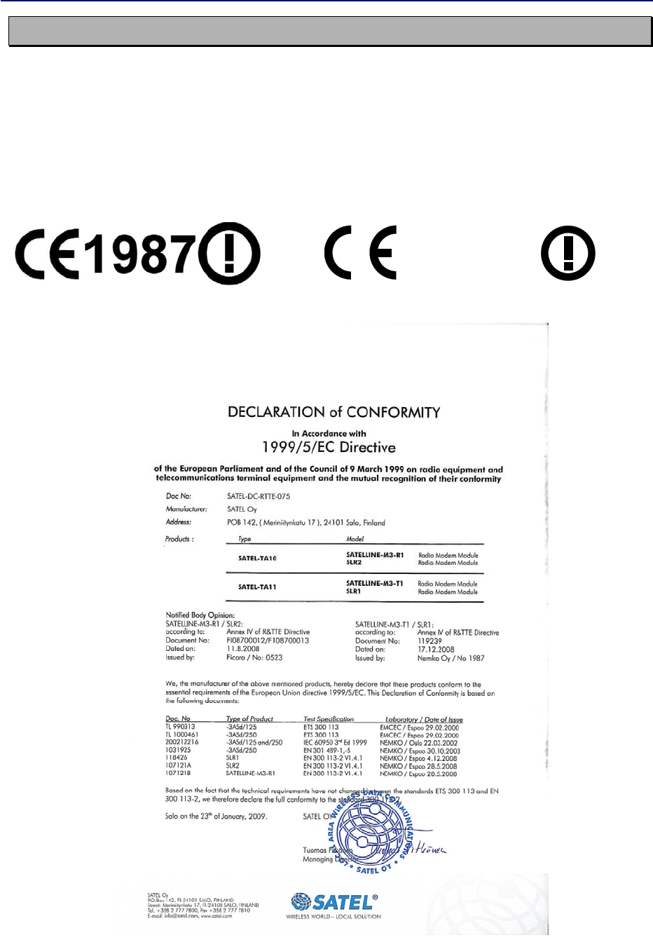
PRODUCT CONFORMITY
SATELLINE-3AS SLR1 and SLR2
Hereby, SATEL Oy declares that SATELLINE-3AS SLR1 and SLR2 radio modem modules are in
compliance with the essential requirements (radio performance, electromagnetic compatibility
and electrical safety) and other relevant provisions of Directive 1999/5/EC. Therefore the
equipment is labelled with the following CE-marking. The notification sign informs user that the
operating frequency range of the device is not harmonised throughout the market area, and the
local spectrum authority should be contacted before the usage of the radio modem.
0523

Version 3.6
5
WARRANTY AND SAFETY INSTRUCTIONS
Read these safety instructions carefully before using the product:
• Warranty will be void, if the product is used in any way that is in contradiction with the
instructions given in this manual, or if the radio modem housing has been opened or
tampered with.
• The radio modem is only to be operated at frequencies allocated by local authorities, and
without exceeding the given maximum allowed output power ratings. SATEL and its
distributors are not responsible, if any products manufactured by it are used in unlawful
ways.
• The devices mentioned in this manual are to be used only according to the instructions
described in this manual. Faultless and safe operation of the devices can be guaranteed only
if the transport, storage, operation and handling of the devices is appropriate. This also
applies to the maintenance of the products.

Version 3.6
6
TABLE OF CONTENTS
IMPORTANT NOTICE ............................................................................................ 2
RESTRICTIONS ON USE ........................................................................................ 3
PRODUCT CONFORMITY ...................................................................................... 4
WARRANTY AND SAFETY INSTRUCTIONS ............................................................. 5
TABLE OF CONTENTS ........................................................................................... 6
1INTRODUCTION ......................................................................................... 8
1.1Description of the products ....................................................................... 8
2TECHNICAL SPECIFICATIONS ...................................................................... 9
2.1SATELLINE-3AS SLR Technical specifications ............................................. 9
2.1.1Power supply ....................................................................................................... 10
2.1.2Hot plugin ........................................................................................................... 10
2.2Basic configuration and installation ....................................................... 11
3SERIAL INTERFACE .................................................................................... 12
3.1D15 connector ......................................................................................... 13
4RF INTERFACE ........................................................................................... 15
4.1Transmitter ............................................................................................. 15
4.2Receiver .................................................................................................. 15
4.2.1RSSI-signal .......................................................................................................... 16
4.3Error correction ....................................................................................... 16
4.4Error checking ......................................................................................... 16
5USER INTERFACE ....................................................................................... 17
5.1LED-indicators ......................................................................................... 17
6TRANSPARENT DATA TRANSMISSION ...................................................... 18
6.1Handshaking lines .................................................................................. 18
6.1.1CTS line .............................................................................................................. 18
6.1.2CD line ............................................................................................................... 18

Version 3.6
7
6.1.3RTS line .............................................................................................................. 19
6.2Pause length ........................................................................................... 19
6.2.1Data buffering in the radio data modem ............................................................... 20
6.2.2TX delay .............................................................................................................. 20
7ADDRESSING ............................................................................................ 21
7.1Addressing .............................................................................................. 21
7.1.1Connection between two points ............................................................................ 23
7.1.2System of one base station and several substations ................................................ 23
8SETTINGS ................................................................................................. 25
8.1SATEL Configuration Manager (CM) software ......................................... 25
8.2Changing parameters using the SL-COMMANDS ................................... 25
8.2.1SL-Command ...................................................................................................... 25
8.3SATELLINE-3AS SLR SL COMMANDS LIST ................................................ 26
8.4Availability of the CM/SL-commands ...................................................... 27
8.5Command table description .................................................................... 29
9PROGRAMMING ....................................................................................... 33
9.1Flash update ........................................................................................... 33
10LABELLING ............................................................................................... 34
11CHECK LIST ............................................................................................... 35
12APPENDIX A ............................................................................................. 36
12.1Functional delays .................................................................................... 36
12.2Transmission related delays ................................................................... 36
Version 3.6
8
1 INTRODUCTION
SATEL OY is a Finnish electronics and Telecommunications Company specialising in the design
and manufacture of wireless data communication products. SATEL designs, manufactures and
sells radio modems intended for use in applications ranging from data transfer to alarm relay
systems. End users of SATEL products include both public organisations and private individuals.
SATEL is the leading European manufacturer of radio modems. SATEL radio modems have been
certified in most European countries and also in many non-European countries.
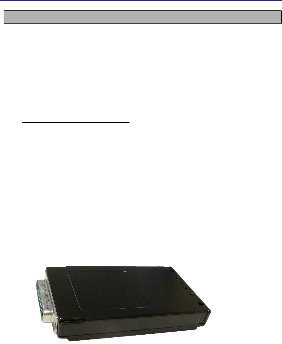
1.1 Description of the products
SATELLINE-3AS SLR2
UHF radio modem receiver module, which provides a transparent data received from SATELLINE
compatible radio modems manufactured by SATEL Oy.
SATELLINE-3AS SLR1
UHF radio modem transmitter module, which generates asynchronous serial input data to radio
frequency and sends it to SATELLINE compatible radio modems manufactured by SATEL Oy.
The modules consist of printed circuit board (PCB), shielding and connector(s). SATEL Oy is
responsible for the required level of EMC characteristics related to the shielding of the
SATELLINE-3AS SLR modules.
The products will later be called as SATELLINE-3AS SLR module
Version 3.6
9
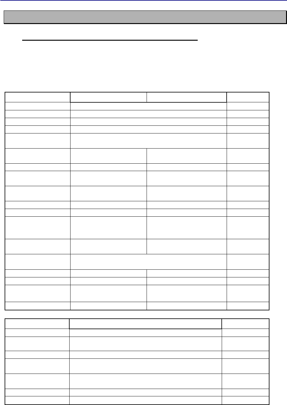
2 TECHNICAL SPECIFICATIONS
2.1 SATELLINE-3AS SLR Technical specifications
SATELLINE-3AS SLR complies with the following international standards:
EN 300 113-2 V.1.4.1, ANNEX A
EN 301 489 (EMC-requirements)
EN 60950 (Safety Standard)
RECEIVER TRANSMITTER Note!
Frequency Range 403...470 MHz
Channel Spacing 12.5 kHz / 20 kHz / 25 kHz
Tuning range 67 MHz
Spurious Radiations < 2 nW
Frequency error
tolerance < 3 kHz
Sensitivity
- 113... -110 dBm
(BER < 10 E-3) FEC On
Co-channel Rejection > 10 dB FEC On
Adjacent Channel
Selectivity > 45/50 dB FEC On
Intermodulation
Attenuation > 55 dB FEC On
Blocking 74 dB FEC On
Spurious Rejection 60 dB FEC On
Spurious Emission -57/-47 dBm
-100dBm on
GPS-
frequencies
Power Consumption,
typical 1.2 W
3 W @ 0.5 W output power.
6 W @ 1 W output power.
Power Consumption,
Sleep ON 0.24 W typical
Type of Emission F1D
Carrier power 100, 200, 500, 1000 mW
A
djacent Channel
Power
300 113 and CRF47 part90
Carrier power stability < ±1.5 dB
DATA MODEM
Timing RS-232
Electrical Interface
CMOS 3.3V
Inputs and Outputs.
(RTS, CTS, RX, TX, +VCC, GND)
Interface Connector D-connector, 15 pole with coaxial inserts (female)
Data speed of
I/O-interface 300 – 38400 bps
Data speed of Radio
Interface
19200 bps ( 25 kHz channel) /
9600 bps (12.5 kHz / 20 kHz channel)
Data Formats Asynchronous data
Modulation 4FSK Optional:GMSK

Version 3.6
10
GENERAL
Operating Voltage + 6.0 ...30 Vdc +/- 5%Vdc
Temperature Range
Type approval condition: -25°C...+55°C.
Working conditions: -25°C...+65°C. See note1.
Storage Temperature -25°C … +55°C
Antenna Connector 50 ohm, D-sub Combo-RF, Female
Construction PCB with sheet metal EMI shields
Size L x W x T 96 mm x 56 mm x 9 mm
Weight 150 g
OTHER MEASURES
ESD-failure threshold 8 kV contact, 15 kV air discharge
Note1. The units are type approved in -25°C...+55°C. However the manufacturer declares
perfect working conditions in -25°C...+65°C.
2.1.1 Power supply
The allowed operating voltage is 6V +/-5% VDC. The radio modem must only be connected to a
power supply with an adequate current output
NOTE! There is a galvanic connection between signal ground (SGND, pin 10), ground (GND,
pin 13), outer conductor of antenna connector and modem casing.
The power cable (+Vb and GND) must be connected to a power supply with a proper output
voltage and with a minimum output current of 1A.
2.1.2 Hot plugin
The modem can be inserted or removed to the DTE-unit without having switched the power
OFF.
Version 3.6
11
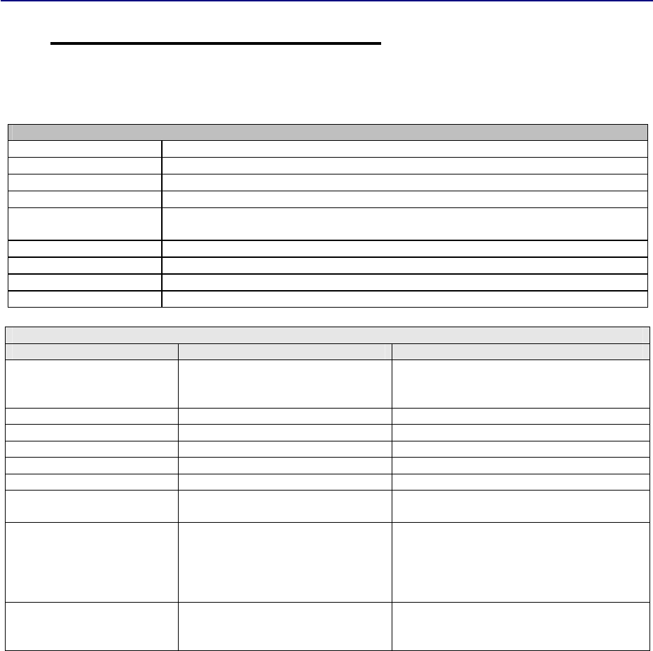
2.2 Basic configuration and installation
The radio modem is shipped with the following default settings (unless otherwise specifically
ordered):
FIXED SETTINGS DEFINED AT THE TIME OF ORDE
R
Radio Frequency Range In accordance with
Customer Order
within 403-470 MHz range
Channel Spacing 12.5 kHz or 25 kHz
(default 25 kHz)
TX Powe
r
0.5 W or 1 W
(default 1 W)
A
ddressing RX Address OFF / TX Address OFF
Serial Port ON / 19200 / 8 bit data / None / 1 stop bit for 12.5 kHz the default data speed is
9600 bps
Pause length 3 characters
Handshaking CTS Clear to send / CD RSSI-threshold / RTS Ignored
A
dditional settings Error Correction OFF / Error check OFF / Extended SL-Commands ON
Tests OFF
A
DJUSTABLE SETTINGS ( user can change these settings later on )
Setting Default value
Notes
Operating frequency 436.500 MHz
A
ny frequency inside the Frequency band.
The receiver and the transmitter frequencies
can be defined individually.
Channel Spacing 25 kHz
Tx Power 1W
FEC OFF
Protocol Satel3AS
Tx Delay 0 ms
Signal Threshold -112 dBm (12.5 kHz, 20 kHz)
-114 dBm (25 kHz)
Serial port 1 settings Data speed=19200 bps
Data bits=8
Parity=None
Stop bits=1
Pause length =3
Handshaking settings CTS=Clear to send
CD=RSSI threshold
RTS=Ignored
Handshaking lines apply to the DATA port.
When creating a test connection, you can either use the Windows based SATEL-Configuration
Manager (CM), (available for free from authorised SATEL dealers or directly from SATEL
Customer Support) or a general terminal program.
Basic settings for the serial port of the host computer, when using a terminal program to
communicate with SATEL radio modems, are as follows: ”COM1, 19200 bps, 8-bit data, none
parity, 1 stop bit”. Use GEV231 (676803) programming cable to connect the SLR radio to a PC
for programming the radio via SATEL_ configuration manager.

Version 3.6
12
3 SERIAL INTERFACE
The radio modem is referred to as DCE (Data Communication Equipment) whereas the PC or
equivalent device is referred to as DTE (Data Terminal Equipment). SATELLINE-3AS SLR radio
module includes a 15-pin ‘D’-type female connector, which contains all the connections
required to establish communication between the radio modem, acting as the DCE, and the PC,
acting as the DTE.
The radio modem contains one serial port, which is designated as Port 1 for communication.
• RD = Receive Data. Output of the data received from the radio modem to the DTE.
• TD = Transmit Data. Input of the data to be transmitted from the DTE to the radio modem.
• CTS = Clear To Send.
• RTS = Request To Send.
• GND = both the negative pole of the operating voltage and the signal ground.
• Vb = positive pole of the operating voltage.
Version 3.6
13
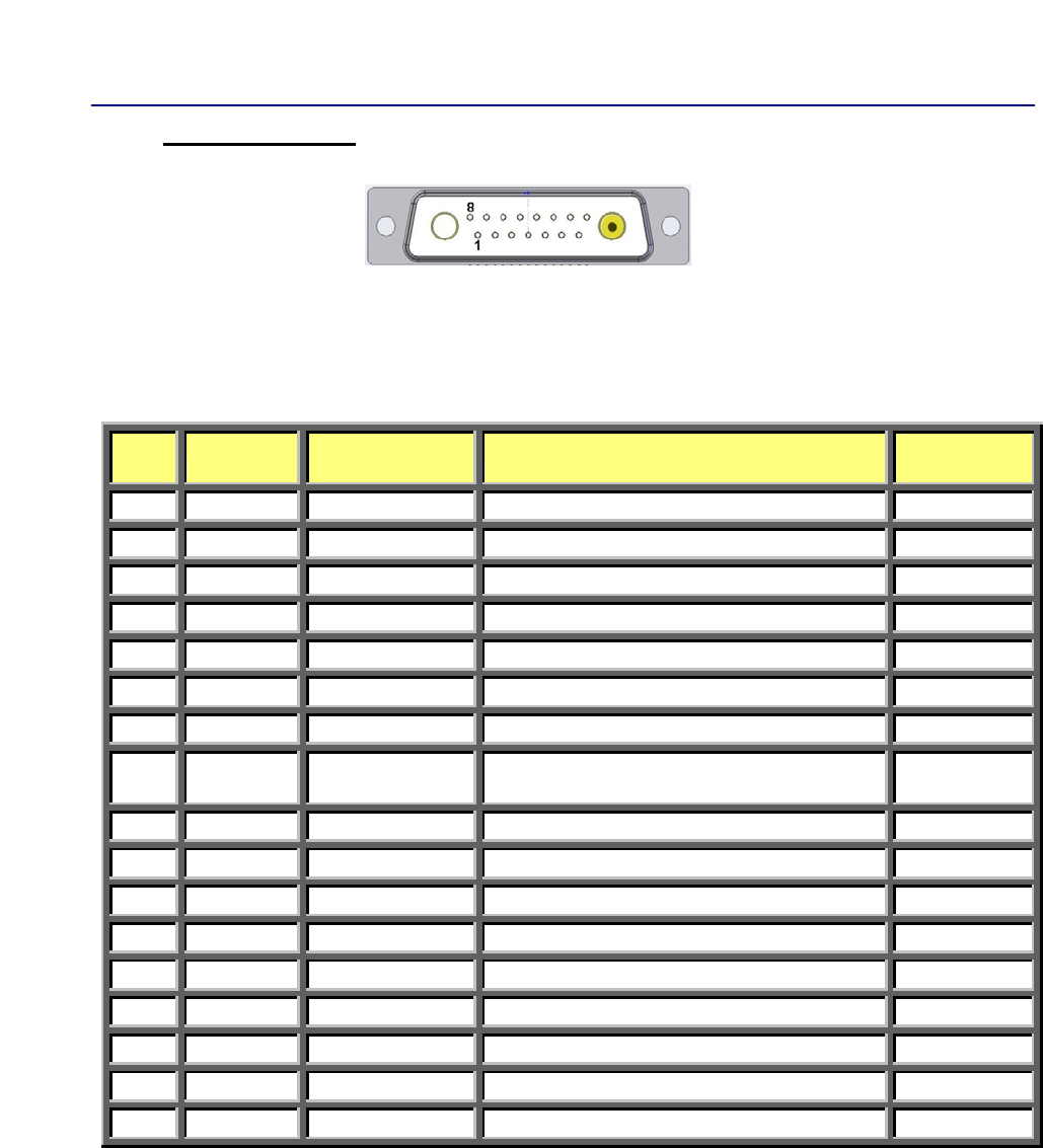
3.1 D15 connector
D-15 female connector in the radio modem
Direction IN is data from DTE (Data Terminal Equipment) to the radio modem.
Direction OUT is data from the radio modem to the DTE.
Pin
No
Signal Type and Direction
Description
Satel
RXO/TXO
1 NC - Not Connected
-
2 TD TTL Input Transmit Data (DTE)
x
3 RD TTL Output Receive Data (DTE)
x
4 GPO/DCD TTL Output General purpose output / Carrier Detect output
x
5 RTS TTL Input Request to Send by DTE
x
6 CTS TTL Output Clear to Send by modem
x
7 CPI/CFG TTL Input General Purpose
Input / Config mode
8 PWR 6.0V Input 6V, +-5% DC Voltage Supply
max.
1.5A^@2W
9 GPIO TTL input/output
General Purpose IO
10 GND GND Signal and Chassis Ground.
x
11 NC - Not Connected
-
12 NC - Not Connected
-
13 GND GND Signal and Chassis Ground
x
14 ID TTL, input/output
1-Wire ID line
x
15 GPIO TTL input/output
General Purpose IO
A
1 NC - Not Connected
-
A
2 RF1
A
ntenna Port UHF Antenna 403-470MHz
*)
NOTE! Unused pins can be left unconnected.
*) FDS062S, female
RF1

Version 3.6
14
Description of pins:
1. NC
Not connected.
2. TD, Transmit data.
CMOS 3.3V. Signal from DTE to modem. Asynchronous serial data.
3. RD, Receive data.
CMOS 3.3V. Signal from modem to DTE. Asynchronous serial data.
4. DCD. Data Carrier Detect.
Output signal from modem. Goes “high” when carrier detected.
5. RTS, Request to send..
CMOS 3.3V. Signal from DTE to modem.
6. CTS. Clear to send.
CMOS 3.3V. Signal from modem to DTE.
7. GPI/CFG.
CMOS 3.3V. General Purpose I/O / Config Mode.
8. PWR
+VDC. Main voltage input. The radio module is designed for 6VDC +/- 5%.
9. GPIO. General Purpose I/O.
Not defined.
10. GND. Ground.
Main voltage minus. Signal and chassis ground.
11. NC.
Not connected.
12. NC.
Not connected.
13. GND. Ground.
Voltage minus. Signal and chassis ground.
14. ID. 1-wire ID-line.
CMOS 3.3V
15. GPIO. General Purpose I/O.
Not defined.
A1. Not in use
A2. RF1. Antenna port.
Antenna connector for UHF 400 – 407 MHz. Input for RXO-module. Output of UHF-signal.

Version 3.6
15
4 RF INTERFACE
The SATELLINE-3AS SLR module has a single Antenna connector with impedance of 50 Ω.
The user can change the frequency of the radio modem afterwards within the frequency range.
The data speed of the radio interface depends on the chosen radio channel spacing. A channel
spacing of 25 kHz enables a data speed of 19200 bps and a channel spacing of 12.5 kHz and
20 kHz enables, correspondingly, a data speed of 9600 bps. The data speed of the radio
interface is always fixed (19200 bps or 9600 bps) irrespective of the data speed of the serial
interface. If the data speeds of the radio interface and the serial interface differ from each other,
the radio modem will buffer the data in transfer temporarily, so no data loss will occur.
4.1 Transmitter
The output power of the transmitter is adjustable between 100, 200, 500 and 1000 mW. The
greatest allowable power depends on limits set by local authorities, which should not be
exceeded under any circumstances. The output power of the transmitter should be set to the
smallest possible level which still ensures error free connections under variable conditions. Large
output power levels using short connection distances can, in the worst case, cause disturbances
to the overall operation of the system.
4.2 Receiver
The Signal Threshold Level setting of the receiver determines a level, above which the search for
the actual data transfer signal is active. If the Signal Threshold Level setting is set too low, it is
possible that the receiver is trying to synchronise itself with noise, in which case, the actual data
transmission might remain unnoticed. Alternatively, weak data transmissions will be rejected,
even though they would be otherwise acceptable.
NOTE!
Setting the radio data modem output power level to that which exceeds the regulations set
forth by local authorities is strictly forbidden. The setting and/or using of non-approved
power levels may lead to prosecution. SATEL and its distributors are not responsible for any
illegal use of its radio equipment, and are not responsible in any way of any claims or
penalties arising from the operation of its radio equipment in ways contradictory to local
regulations and/or requirements and/or laws.
Version 3.6
16
4.2.1 RSSI-signal
RSSI-signal (Received Signal Strength Indicator) gives an indication of the strength of the
received radio signal. This signal can be used to determine the approximate signal level. The
RSSI–signal can be set and read using the SL-command.
4.3 Error correction
Error correction mode called the FEC-method (Forward Error Correction). When activated, the
FEC-function will cause the SATELLINE-3AS SLR to automatically add additional error correction
information, which increases the amount of transmitted data by 30 %. It is used by the receiving
radio modem to correct erroneous bits - as long as the ratio of correct and erroneous bits is
reasonable.
Error correction improves the reliability of data transfer via the radio interface especially in
unfavourable conditions. FEC-function should be used when link distances are long and/or if
there are many disturbances in the radio channels used. The use of the FEC-function will,
however decrease the data transfer throughput of data by about 30 %.
4.4 Error checking
When the error checking is switched on, the radio modem will add a checksum to the
transmitted data. When the data is received, the checksums are verified before data is forwarded
to the serial port.
NOTE!
All radio modems, which are to communicate with each other, must have the same setting
for FEC (ON or OFF). If the transmitting radio modem and the receiving radio modem has
different settings, data will not be received correctly.
Version 3.6
17
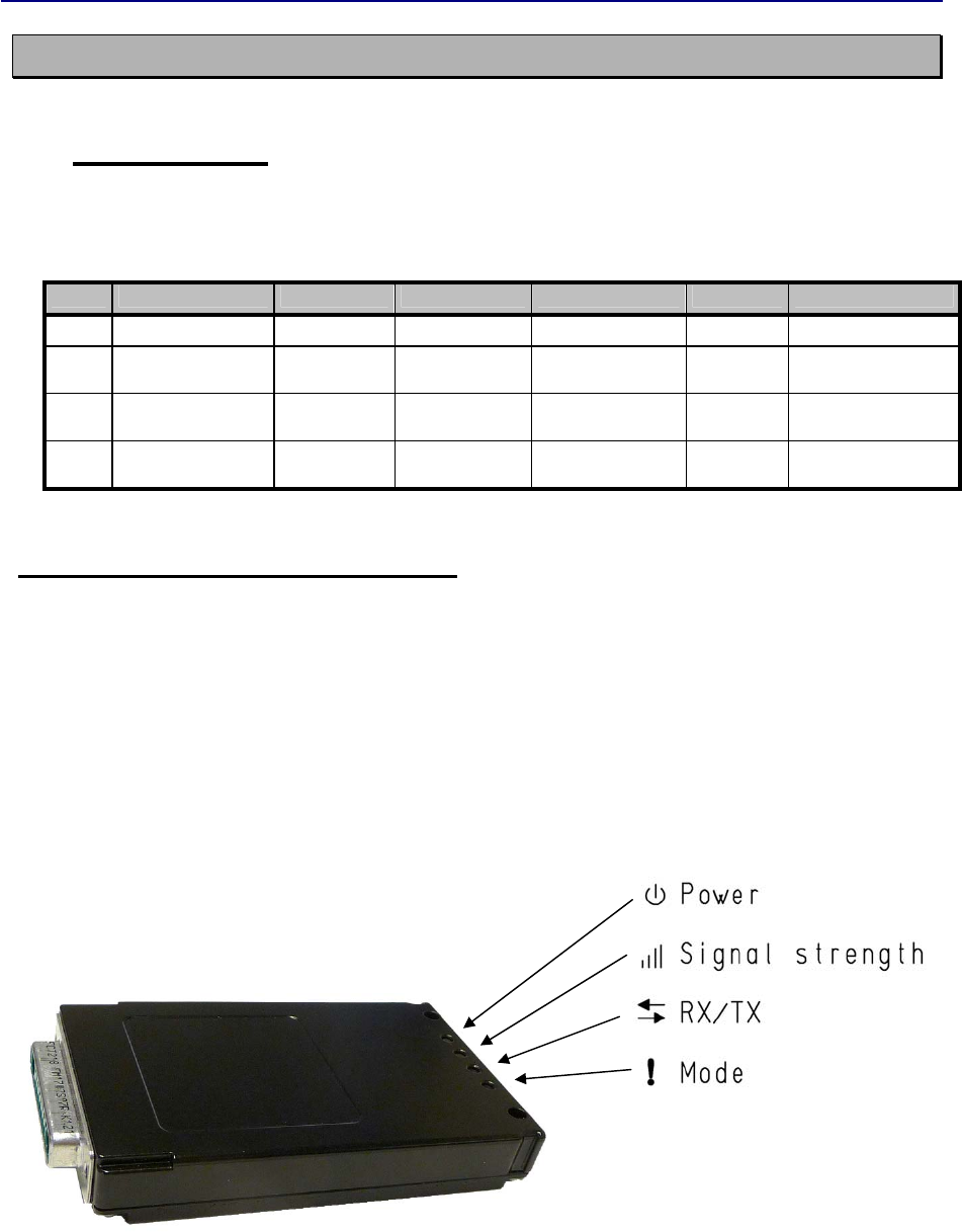
5 USER INTERFACE
5.1 LED-indicators
There are four (4) LED indicators on the front panel of the radio modem, and they give an
indication of the status of the serial port and the radio interface:
LED Indication OFF Red
Red, Flashing
Green Green, flashing
Power ON/OFF Inactive
A
ctive
RSSI Signal strength No data Data detected
and ok
Data detected,
but weak signal
RX/TX Data indicator No data
transferred
Data transfe
r
Mode Communication
or programming
Data Mode
Programming
mode
Description of the LED-indicators:
• Power indicates the status of Power ON/OFF
• RX/TX indicates that the radio modem is receiving or transmitting data via serial port.
• RSSI indicates the strength of the received signal
• Mode indicates whether the modem on Data- or Programming mode.

Version 3.6
18
6 TRANSPARENT DATA TRANSMISSION
6.1 Handshaking lines
When using the serial interface, handshaking signals can be used to control data transfer on the
DATA port. For example, the radio modem can inform the DTE that the radio channel is busy,
and that it is not allowed to initiate transmission.
A common way of using handshaking signals is to monitor the CTS line and ignore the others.
Usually the terminal device is fast enough to handle the data received by the radio modem, so
the use of RTS line is not necessary.
Handshaking is not needed if the system protocol is designed to prevent collisions (data
contentions) by using poll queries, or if there is only little traffic and, if there is no harm from
occasional data contention situations (two or more radio modems trying to transmit at the same
time).
6.1.1 CTS line
CTS (Clear To Send) is a signal from the radio modem to the DTE. It indicates when the radio
modem is ready to accept more data from the DTE. The options for CTS line controls are:
1) Clear To Send
CTS line is set active when the radio modem is ready to accept data for transmission. CTS will
shift into inactive state during data reception, and when a pause (packet end) is detected in
transmitted data. CTS shifts back into active state either when reception ends or the radio
modem has finished data transmission. CTS will also shift into inactive state when the serial
interface data transfer speed is greater than the radio interface transfer speed, and the transmit
buffer is in danger of overflowing.
2) TX buffer state
CTS line will shift into inactive state only when the data buffer for the data to be transmitted is in
danger of overflowing.
6.1.2 CD line
CD (Carrier Detect) is a signal from the radio modem to the DTE. It indicates when there is
activity on the radio channel. The options for CD line controls are:
1) RSSI-threshold
CD is active whenever a signal exceeding the defined threshold level required for reception,
exists on the radio channel. It doesn’t make any difference, whether the signal is actual data
transmission, a signal of a radio transmitter not belonging into the system or even interference
caused e.g. by a computer or some other peripheral device. CD is also active, when the radio
modem itself is transmitting (only TX-version).

Version 3.6
19
2) Data on channel
CD will switch to active state only after recognizing a valid data transmission from another
SATELLINE-3AS NMS family radio modem. CD will not react to interferences like noise or
possible other signals.
3) Always ON
CD is always in the active state. This option is usually used with terminal equipment using the
CD line as an indicator of an active connection. In this case the radio modem can transmit or
receive data at any time.
6.1.3 RTS line
RTS (Ready To Send) is a signal from the DTE to the radio modem. DTE controls the data flow
from the radio modem by using RTS. The options for RTS line controls are:
1) Ignored
RTS line status is ignored.
2) Flow control
The radio modem transmits data to the terminal device only when the RTS line is active. Inactive
state of the RTS line will force the radio modem to buffer the received data. This option is used,
when the terminal device is too slow to handle data received from the radio modem.
3) Reception control
RTS line controls the reception process of the radio modem. An active RTS line enables
reception. Inactive RTS line will interrupt reception process immediately, even if the radio
modem is in the middle of receiving a data packet. This option is used to force the radio modem
into WAIT State for an immediate channel change.
6.2 Pause length
The radio modem recognizes a pause on the serial line (a pause is defined as a time with no
status changes in the TD line). The pause detection is used as criteria for:
- End of radio transmission - When the transmit buffer is empty and a pause is detected, the
modem stops the transmission and will change the radio to the receiving mode
- SL command recognition - For an SL command to be valid, a pause must be detected before
the actual “SL“ prefix of the SL command.
- User address recognition
In order for detecting the message, a pause must precede it in transmission.
Traditionally, in asynchronous data communication, pauses have been used to separate serial
messages from each other. However the use of non-real-time operating systems (frequently used
on PC type hardware) has changed this tradition by adding random pauses in the asynchronous
data stream. Such systems can’t serve the hardware UART properly when performing other tasks
(other applications or tasks of the operating system itself). The pauses described above are
typically up to 100 ms. When such a pause appears in the middle of a user message, the radio
modem transmits the message as two separate radio transmissions. This will generate problems
in at least two ways:

Version 3.6
20
1) The inter-character delay will be increased by at least the time of the modem transfer delay
2) The probability of collisions on the radio path will increase. This will be especially harmful for
repeater chains
The default value for the Pause length is 3 bytes.
6.2.1 Data buffering in the radio data modem
A synchronisation signal is transmitted at the beginning of each radio transmission and this
signal is detected by another radio modem, which then turns into receive mode. During the
transmission of the synchronisation signal the radio modem buffers the data to be transmitted
into its memory. Transmission ends when a pause is detected in the data flow sent by the
terminal device, and after all the buffered data has been transmitted. When the data speed of
the serial port is the same or slower than the speed of the radio interface, the internal transmit
buffer memory can not overflow. However, when the serial interface speed exceeds the speed of
the radio interface, data will eventually fill the transmit buffer memory. After the terminal device
has stopped data transmission, it will take a moment for the radio modem to get the buffered
data transmitted and get the transmitter switched off. The maximum size of transmit buffer
memory is one kilobyte (1 kb). If the terminal device does not follow the status of the CTS line
and transmits too much data to the radio modem, the buffer will be cleared and the
transmission is restarted.
In the receiving mode, the data coming from the radio is also buffered thus evening out
differences in data transfer speeds at the serial ports.
6.2.2 TX delay
The radio modem can be configured to delay the beginning of a radio transmission by
1...65000 ms. During this delay data sent to the radio modem is buffered.
Version 3.6
21
7 ADDRESSING
7.1 Addressing
Addresses can be used to route a data message to the desired destination or to separate two
parallel networks from each other. In networks with repeaters it is usually necessary to use
addresses to prevent data messages from ending up in loops formed by repeaters.
SATELLINE-3AS SLR radio modules allow the use of individual addresses either for reception or
for transmission respectively.
The radio SLR1 module contains one transmission address and the SLR2 one reception address,
which are known as the primary addresses. The primary address is used whenever data from the
serial interface is transmitted.
It is also possible to transfer the received address onto the serial interface.
The address is composed of two characters totalling 16 bits, resulting in over 65,000 different
address combinations. The address is attached to the beginning of each data packet sent by the
SLR1. When the SLR2 receives a data packet whilst using addressing mode, the radio modem
will check the first two characters of each received data packet to ensure that the packet in
question was intended for the correct radio modem.
ADD H ADD L DATA
Address may be selected between 0000h…FFFFh (h = hexadecimal, corresponding decimal
numbers are 0-65535).
Example: address 1234h (4660 in decimal format), where 12h is ADD H and 34h is ADD L.
Example: address ABFFh (44031 in decimal format), where ABh is ADD H and FFh is ADD L.
Version 3.6
22
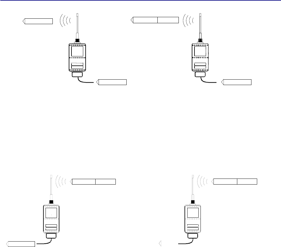
Transmission:
Data Address Data
DataData
Transmission address has been set OFF.
Radio modem will transmit the data
packet as such.
Transmission addressing has been set
ON. The radio modem will add the
primary TX address to the beginning of the
data packet.
Reception:
Reception addressing has been set ON
and either the primary or secondary RX
address of the radio modem is identical to
the address of the received data packet.
The radio modem will remove the address
and send the actual data to the RS-232
interface.
However, if the ”RX Address to RD-line”
setting is on, the radio modem does not
remove the address.
Reception addressing has been set ON,
but both the primary and secondary RX
addresses of the radio modem are
different from the address of the received
data packet.
Data does not appear on the RS-232 -
interface.
Address Data
Data
Address Data
Version 3.6
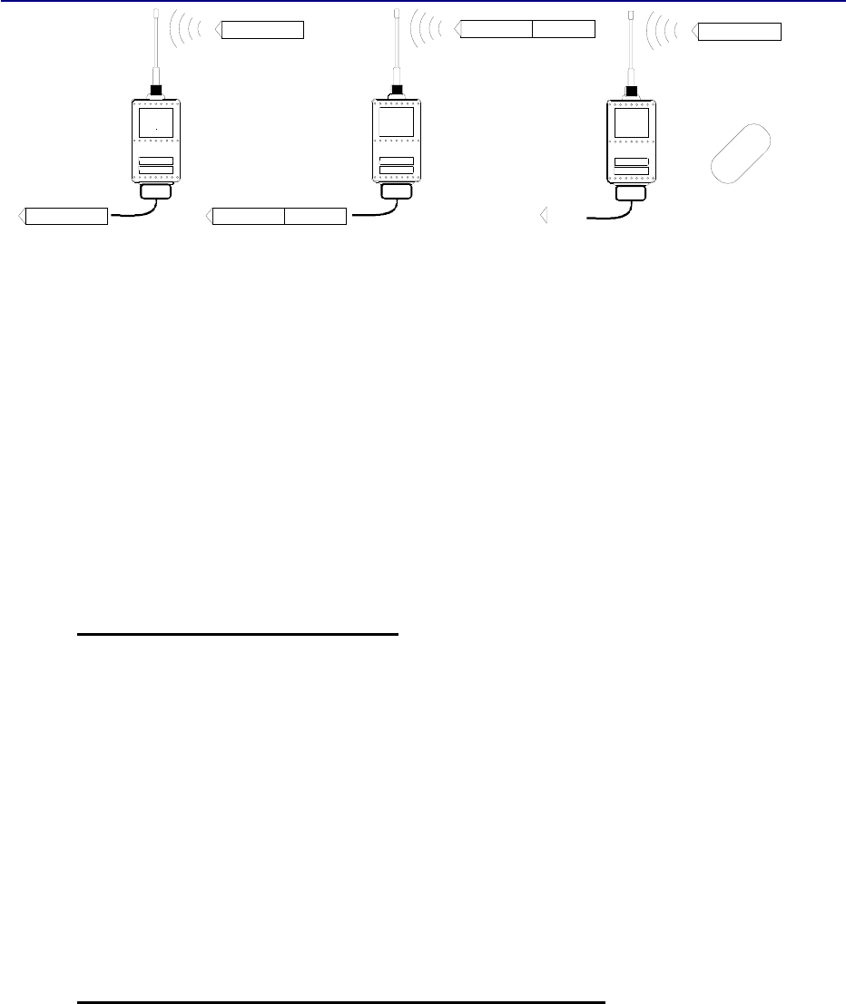
23
Reception addressing
has been set OFF.
The radio modem will
transfer all received
data to the RS-232 -
interface.
Reception addressing has
been set OFF.
The radio modem will
consider the characters of
the address as a part of the
data and will send all the
characters to the RS-232
interface.
Reception addressing has
been set ON but there is
no address in the data
packet.
Data will appear on the RS-
232 interface ONLY if the
first 2 characters of the
data match either of its own
RX address. The radio
modem will remove those 2
characters of data.
7.1.1 Connection between two points
When forming a connection between two points it is recommended that both the reception and
transmission addresses are identical in both radio modems. This is the easiest way to control
addresses and the risk caused by interference from other systems operating in the same area is
minimal.
Example: by setting all addresses of both radio modems to a value ´1234´, they will accept
only those messages which contain this address, and they will use this same value when
transmitting data.
If the channel is reserved for use only by the said network, or if the terminal devices are
responsible for addressing, it is not necessary to use addressing in the radio modems.
7.1.2 System of one base station and several substations
In systems with several substations, the base station must know to which substation each
message is intended, and from which substation each received message originates. Usually
terminal devices handle addressing completely, but it is also possible to use the addressing
functionality of the radio modems.
For example, if the substation terminal devices are not able to check and form addresses by
themselves, addressing may be achieved with the help of the addresses of the radio modems
Data
Data
Data
Address Data
Address Data
ERROR

Version 3.6
24
attached to these terminal devices. The base station may, in such a case, define the destination
of a message by adding the address of the corresponding radio modem into the beginning of
the data packet. The substation radio modem(s) will check the address and the corresponding
radio modem will identify and remove the address characters.
Version 3.6
25
8 SETTINGS
The configuration of SATELLINE-3AS SLR radio module can be easily changed simply by
connecting the module to the PC and using SATEL CM or DTE. Programming is done using the
serial port of the module. The serial port settings are 9600 bps, N, 8, 1 (data transfer speed
9600 bps, no parity, character length 8 bits and one (1) stop bit).
8.1 SATEL Configuration Manager (CM) software
The SATEL Configuration Manager is a configuration and setup software that is explained in a
separate User Manual.
8.2 Changing parameters using the SL-COMMANDS
The controlling terminal device can change the configuration settings of a radio modem. This is
accomplished with the help of SL-commands, which can be used during data transfer. SL-
commands can be used to change e.g. the frequency or addresses. It is also possible to
interrogate a radio modem in order to gain information concerning current settings that are in
use. The terminal device is either a PC or a programmable logic (PLC) together with suitable
(terminal) program.
8.2.1 SL-Command
An SL-command is a one continuous string of characters, which is separated from other data by
pauses that are equal or greater than time defined by Pause length parameter (see chapter
Pause Length) in the set-up. No extra characters are allowed at the end of an SL-command.
Serial interface settings are the same as in data transfer. SL-command is properly recognised
also in the case when the command string is terminated in <CR> (=ASCII character no. 13,
Carriage Return, 0x0d) or <CR><LF> (<LF> = ASCII char. no. 10, Line Feed, 0x0a). If
multiple SL commands are sent to the radio modem the next command can be given after
receiving the response ("Ok" or "Error") of the proceeding command. In addition, it is
recommended to implement a timeout to the terminal software for recovering the case when no
response is received from the radio modem.
When the power of a radio modem is switched off the configuration settings of a radio modem
returns to values defined initially or as saved using SL-commands.
The radio modem will acknowledge all SET commands by returning an "OK" (command carried
out or accepted) or the requested value, or an "ERROR" (command not carried out or interpreted
as erroneous) message. “Question” is responded to with a value (Note! A question is not
answered as “OK”). The SL-commands are set ON using a relevant SL-command.

Version 3.6
26
8.3 SATELLINE-3AS SLR SL COMMANDS LIST
SL Nr.
A
ddressing related Effect and description of command
(These commands are NOT applicable in this application)
14 SL#I=xxxx Set all addresses (RX1, RX2, TX1, TX2) to value xxx
x
15 SL#I? Display both primary addresses (TX1, RX1) (response ’xxxx;yyyy’)
16 SL#T=xxx
x
Set both transmit addresses (TX1, TX2) to value xxx
x
17 SL#T? Display primary transmit address (TX1) (response ‘xxxx’)
18 SL#R=xxxx Set both receive addresses (RX1, RX2) to value xxx
x
19 SL#R? Display primary receive address (RX1) (response ‘xxxx’)
20 SL#P=xxxx;yyyy Set primary transmit address (TX1) to value xxxx and receive address
(RX1) to value yyyy
21 SL#S=xxxx;yyyy Set secondary transmit address (TX2) to value xxxx and receive address
(RX2) to value yyyy
22 SL#P? Display primary transmit address (TX1) and receive address (RX1)
(response ‘xxxx;yyyy’)
23 SL#S? Display secondary transmit address (TX2) and receive address (RX2)
(response ‘xxxx;yyyy’)
24 Note: xxxx and yyyy below mean address in the hexadecimal format (0000 … FFFF)
Other radio related Effect and description of command
26 SL@P=xxxx
x
Set the RF output power, where xxxxx is the decimal value of the intended
power in milliwatts. If the given value does not correspond to one of the
programmed power levels, the output power is set to the nearest possible
value.
27 SL@P? Requests the RF output power.
Response ”xxxxx mW”, where xxxxx is a decimal value the output power
of the transmitter.
28 SL@T=-xxx Set the minimum power level of the signal to be received (="Signal
Treshold level), where xxx is a decimal value of the new intended level in
dBm.
FCS related Effect and description of command
36 SL!D? Returns the lower limit for band 1
37 SL!U? Returns the upper limit for band 1
38 SL!W? Returns the lower limit for band 2
39 SL!Y? Returns the upper limit for band 2
Other SL commands Effect and description of command
52 SL!V? Returns modem type:
• "3AS "
• "3AS (d) "
• "3AS-SLR2"
• "3ASrm" for receiver module.
53 SL%V? Display software revision information (response ’Vn.nn’)
59 SL+S=1 Sets the unit to SLEEP-mode and reduces STDBY-current.
60 SL%P=1 Set the unit to Programming mode

Version 3.6
27
8.4 Availability of the CM/SL-commands
See table below.
details
10.1.x
Function Supported
by
modem
Supported
by CM
(Dealer
version)
Supported
by CM
(User
version)
Supported by
Customer’s Data
Terminal
Equipment, DTE
(=SL-command)
Comments
SL-command
SL Nr.
1 Create channel
list
no yes definable no
No
2 Set channel yes yes definable yes new: SL$F=nnnn
3 SET Default
Channel
no yes definable yes
new: SL$D=nnnn
4 Go to Default
Channel
yes yes definable yes
new: SL$A=1
5 Read Default
Channel
yes yes definable yes
new: SL$D?
6 Export channel
table to file
no yes definable no
No
7 Import channel
table from file
to CM
no yes definable no
No
8 Read current
settings from
modem
yes yes definable no DTE: Only
one-by-
one
9
Read factory
settings like:
model, serial
number, FW-
version,
frequency band,
module ID
yes yes definable yes DTE: Only
one-by-
one
52
53
36
37
38
39
52 - model: SL!V?
serial number: SL%S?
53 - sw: SL%V?
36 - b1 low: SL!D?
37 - b1 high: SL!U?
38 - b2 low: SL!W?
39 - b2 high: SL!Y?
module ID: SL%H?
10 Send settings to
modem
yes yes definable yes DTE: Only
one-by-
one or by
special
exe-file
11 Channel
scanning mode
(only on RX)
yes no no yes
new: SL$S=1 (shows RSSSI-values)
12 Search free
channel
(only on RX)
yes no no yes
new: SL$E=1
13 Assign
frequencies to
channel
numbers (min
20 channels)
yes yes definable no
No
14 Set channel
spacing:12.5,
20 or 25 kHz
yes yes definable no
SL&W=xxxx (xxxx=1250, 2000 or
2500)

Version 3.6
28
15 Addressing yes yes definable no 14
15
16
17
18
19
20
21
22
23
14 - SL#I=xxxx
15 - SL#I?
16 - SL#T=xxxx
17 - SL#T?
18 - SL#R=xxxx
19 - SL#R?
20 - SL#P=xxxx;yyyy
21 - SL#S=xxxx;yyyy
22 - SL#P?
23 - SL#S?
SL#Q=e
SL#W=e
SL#Q?
SL#W?
SL#A=xxxx,yyyy,zzzz,wwww
SL#A?
16 Configure
communication
port parameters
yes yes definable yes
SL%B= only speed
17 SLEEP yes no no yes 59
59 - SL+S=1
18 Set FEC yes yes definable no No
19 Print actual
settings from
modem
yes yes definable no
No
20 Additional
settings (auto
baud rate
detection…)
no yes definable no
No
21 Describe
settings via
"Help" Tool
no yes yes no
No
22 Show used
COM port of
PC
no yes yes no
No
23 Update
firmware
yes yes definable no
60 60 - SL%P=1 and
SLFLOEM
24 Set protocol
format: SATEL
3As, PCC
TrimTalk
yes yes definable no
No
25 Read SW-
version
yes yes definable yes
53 53 - SL%V?
26 Read HW-
version
yes yes definable yes
SL%H? (new)
27 Power down no yes definable yes No
28 Output power
configurable in
W and or dBm
yes yes definable yes
27
26
27 - SL@P?
26 - SL@P=nnn
29 Max. output
power
yes yes definable no
No
30 Configure
handshaking
parameters
yes yes definable yes No
31 Set
programming
mode
yes yes definable no
60 60 - SL%P=1
32 Read RSSI-
threshold
yes yes definable yes
27 27 - SL@T?
32.1 Reset modem yes no no yes 32.1
SL@X=9
32.2 Set 3AS-mode yes yes no yes 32.2
SL@S=0
32.3 Set Option 1 yes yes no yes 32.3
SL@S=1
32.4 Set Option 2 yes yes no yes
32.4 SL@S=2
32.5 Read mode yes yes no yes 32.5
SL@S?
33 SET RSSI-
threshold
yes yes definable yes
28
28 - SL@T=-xxx
34 Read noise level no no no yes
SL@F?
35 Read message
level
no no no yes
SL@R?

Version 3.6
29
8.5 Command table description
1. Create channel list. CM. No DTE
The channel list is generated by the CM. The ready-made list is sent to the modem by the CM.
The maximum number of channels on the list is 40. When the modem is powered ON it goes to
the default channel.
2. Set channel. CM and DTE
The operating channel can be manually set by the CM, or selected from the list by the DTE.
3. SET Default Channel. CM and DTE
Assigns the default channel.
Note1!
1. If the Default Channel is not set the modem uses the Factory Default Frequency.
2. If the Channel List is established the Default Channel is the 1st Channel in the list.
Note2!
When the modem is switched ON
- the modem uses the Default Frequency set by the Factory, if no other settings are done, or
- the User frequency that is set by the SATEL Configuration Manager, if the Channel List has not
been used before switching OFF, or
- the frequency that is set by the Channel List as 1st Channel, if the User frequency has not been
used before switching OFF.
4. Go to Default Channel. DTE
Modem goes to the channel which is assigned as default channel.
5. Read Default Channel. CM and DTE
Reads default channel from the modem.
6. Export channel table to file. CM
Saves channel table PC.
7. Import channel table from file. CM.
Load settings from file to CM.
8. Read current settings from modem. CM. DTE one-by-one.
All settings can be read by the CM. The DTE can read settings one-by-one, because there is no
such an SL-command that will read all settings using only one command.
9. Read factory settings. CM. DTE one-by-one.
Model, serial number, FW-version, frequency band and module ID can be red from the modem
using the SL-commands.
Read Model = SL No. 52, serial no= SL ?, FW-version = SL 53, frequency band= SL 9, 10,
Module ID= SL 55.

Version 3.6
30
10. Send settings to modem. CM. DTE one-by-one.
Settings to the modem can be sent by the CM. The DTE can send settings one-by- one or by the
or using a special exe-command.
11. Channel Scanning feature. DTE
When activated the modem scans channels one by one and saves the RSSI readings to memory.
The respond to the DTE is; 1st RSSI, 2nd RSSI, 3rd RSSI and so on.
12. Search Free channel. DTE
When activated the modem searches for the next channel which is free from traffic. The listening
time of the traffic is about 2 seconds. The response is “channel xx is free”. By activating same
command again, the modem shows the next free channel.
13. Assign Frequencies to channel numbers. CM
All possible frequencies, which are available by the modem type, are listed in the CM. The user
can pick up maximum of 16 frequencies and assign them channel numbers.
14. Set Channel Spacing. CM
Channel spacing must be assigned to the list or every channel separately. The alternatives are
12.5 kHz, 12.5 kHz or 25 kHz.
Note that there can be only one channel spacing alternative per channel.
15. Addressing. CM
Defines addresses to the receiver and transmitter.
16. Configure communication port parameters. CM and DTE.
Configurable parameters are Baud Rate, Parity, Number of Data Bits, Number of Stop Bits.
17. SLEEP. DTE
Special SL-command, SL+S=1 (which shuts down power units, synthesizers, and processor to a
low power sleep mode)
Waking up from SLEEP is done if by sending a character to the modem. Wake-up time is about
40ms, before the modem is ready to receive data.
18. Set FEC. CM .
Sets the Forward Error Correction ON/OFF.
19. Print actual settings from modem. CM
Read settings from modem and makes it possible to print settings as a list.
20. Additional settings (auto baud rate detection…) Optional. CM.
When activated, the PC will start polling the modem (HW-version) with different baud rates, and
other values. When recognized the PC knows modem’s port settings. The response is “modem
found on port” or no modem found.
21. Describe settings via "Help" Tool. CM
CM shows help info when cursor is kept on the ?-mark. It is also possible to make different
languages on the help menu. The languages are made by special configuration tool. The
language can be selected by the user.

Version 3.6
31
22. Show used COM port of PC. CM.
Shows the COM-port status of the PC.
23. Update Firmware. CM.
The FW can be load from the PC to the Modem. The modem can be programmed with or
without Programming PIN.
24. Set Protocol format. Satel, PCC, Trim Talk. CM.
Set modulation type 3AS /FSK, PCC and TrimTalk/GMSK.
Read modulation type from the modem.
25. Read SW-version. CM. DTE
Read SW-version from the modem.
26. Read HW version. CM.
Read HW-version from the modem.
27. Power down. DTE. Not used in this version.
Power ON/OFF can be driven by the DTR-pin. Power ON, when DTR=open or +Vb. Power
OFF, when DTR= ground.
28. Output Power configurable in Watt or dBm. CM and DTE.
Shows the output power ether in Watt or dBm.
29. Max. Output Power. CM and DTE.
Sets the output power.
This command sets the maximum output limit that can be set by the DTE-unit. This limit can not
be changed by the DTE-unit.
30. Configure handshaking parameters. CM and DTE
The handshaking parameters
31. Set programming mode. CM.
Sets unit to programming mode.
32. Read RSSI-threshold. CM and DTE
Shows the RSSI-threshold level.
32.1 Reset modem.
Resets modem. This command switches OFF the modem, and does not retrieve ok.
32.2 Set Satel 3AS-mode.

Version 3.6
32
32.3 Set Option1
This Option is 4FSK-mode.
When this mode is used the other values are must be:
SATEL Modem PCC Modem
FEC: OFF Forward Error Correction: ON
Baud Rate: 19200 Scrambling: ON
Addressing: Not available Protocol Mode: Transparent Mode w/EOT Timeout
32.4 Set Option2
This Option is GMSK-mode
When this mode is used the other values are must be:
SATEL Modem PCC Modem
FEC: OFF Forward Error Correction: ON
Baud Rate: 9600 Scrambling: ON
Addressing: Not available Protocol Mode: Transparent Mode w/EOT Timeout
32.5 Read Option
Read the current Option
The Modem retrieves:
“0” when in 3AS-mode.
“1” when in Option 1-mode.
“2” when in Option 2-mode.
33. Set RSSI-threshold. CM.
Sets the RSSI-signal threshold level.
The RSSI Signal Threshold setting of the receiver determines the level that the modem operates
properly. The number is shown as [–dBm], so the greater the number is the weaker is the signal
threshold level (-100 dBm is weaker than -90 dBm).
The modem operates only, if the received signal is stronger than the Signal Threshold level.
When set, it applies to all channels and frequencies.
If the environment is noisy and it is needed that the modem does not listen to noisy channels, it
is usually recommended to use a value that is about 10 above noise level.
Example of noisy environment:
Noise level measurement, SL@F?, retrieves [-100 dBm] ==> RSSI threshold level should be set
to -102...-98 dBm, so the receiver will not try to find a signal from the noise.
The recommended value under normal circumstances is about -117.
The available values are -80... -118 dBm.
34. Read noise level. DTE
Shows the noise level of the channel/frequency.
35. Read message level. DTE.
Shows the level [– xxx dBm] of the last message if received within 7 seconds from the SL-
command. If no messages received within 7 seconds from the SL-command, the modem
retrieves -118dBm, which means “no reading received”.

Version 3.6
33
9 Programming
9.1 Flash update
The Firmware can be updated to in two ways:
• By using terminal program. Instructions to use this method are given by request.
• By using Configuration Manager (CM) , which requires The Satel Configuration Manager, a
cable adapter between the module and a PC with serial port.
Version 3.6
34
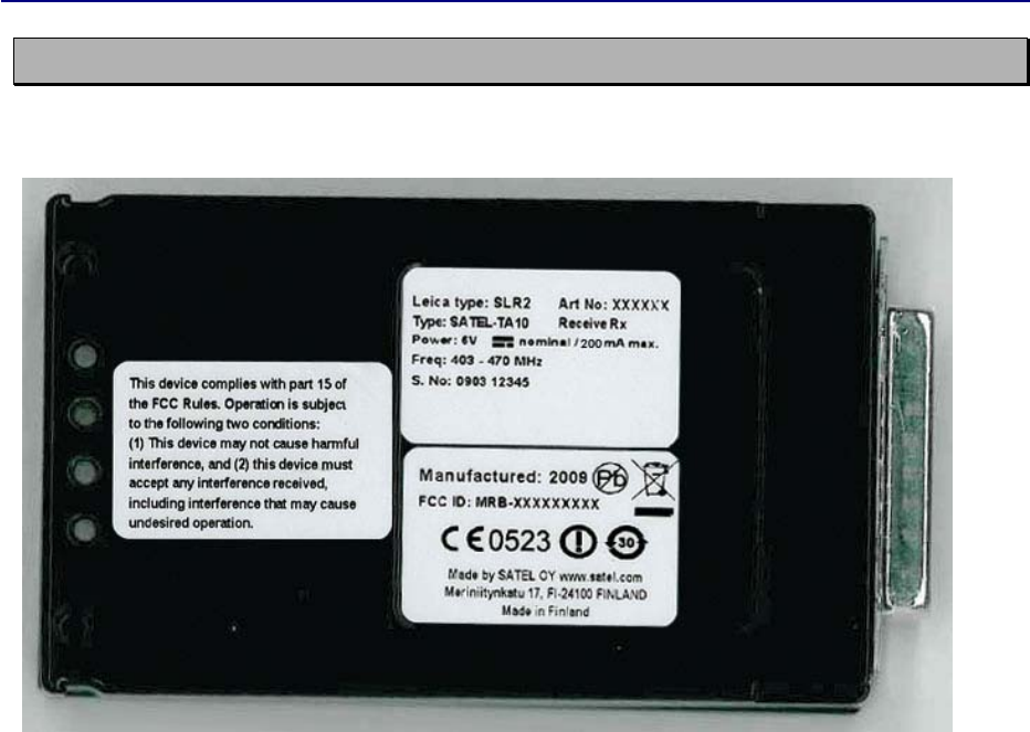
10 LABELLING
Label on the left: Warnings for users in North America
Label on the right:
- Top: Type label for product
- Bottom: Type approval -label

Version 3.6
35
11 CHECK LIST
The following points must be taken into account when installing and configuring a radio
modem:
1. All operating voltages of all the equipment concerned must always be switched OFF before
connecting the serial interface cable.
2. When considering the exact placement of a radio modem and/or its antenna, the following
points must be taken into account to guarantee optimal results:
• The antenna should be installed in open space as far as possible from any possible sources
of interference
• The radio modem should not be installed onto a strongly vibrating surface
• The radio modem should be installed in such a way as to minimise exposure to direct
sunlight or excessive humidity.
3. To ensure reliable operation the voltage output of the power supply used must be stable
enough and the current capability of the power supply must be sufficient.
4. The antenna must be installed according to instructions.
5. Settings of the radio modem must correspond to settings of the terminal.
6. All radio modems in the same system must be configured using same settings (radio
frequency, channel spacing and data field length).
Version 3.6
36
12 APPENDIX A
12.1 Functional delays
Function Delay (ms)
Time from turning power ON, until it is ready to
send/receive data
<300
ms
Wake-up time from SLEEP, until it is ready to
send/receive data
<95
ms
Serial interface, turnaround time of RS-232
0
Inter character delay max. 2-3 characters
SL-Ping response time from remote modem
129
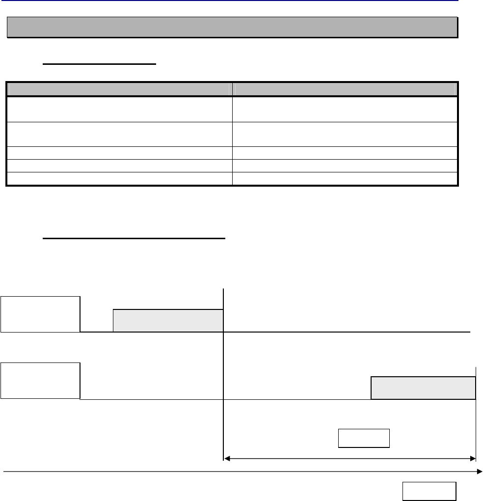
12.2 Transmission related delays
Delay from the end of transmission to the end of reception on the serial interface:
Modem 1
TD-line
Modem 2
RD-line
Delay
Time
start end
start end
DATA
DATA