Sato Vicinity MARS-24E MARS-24 RFID DESKTOP READER User Manual USERS MANUAL
Sato Vicinity Pty Ltd MARS-24 RFID DESKTOP READER USERS MANUAL
UserManual.wiki
>
Sato Vicinity
>
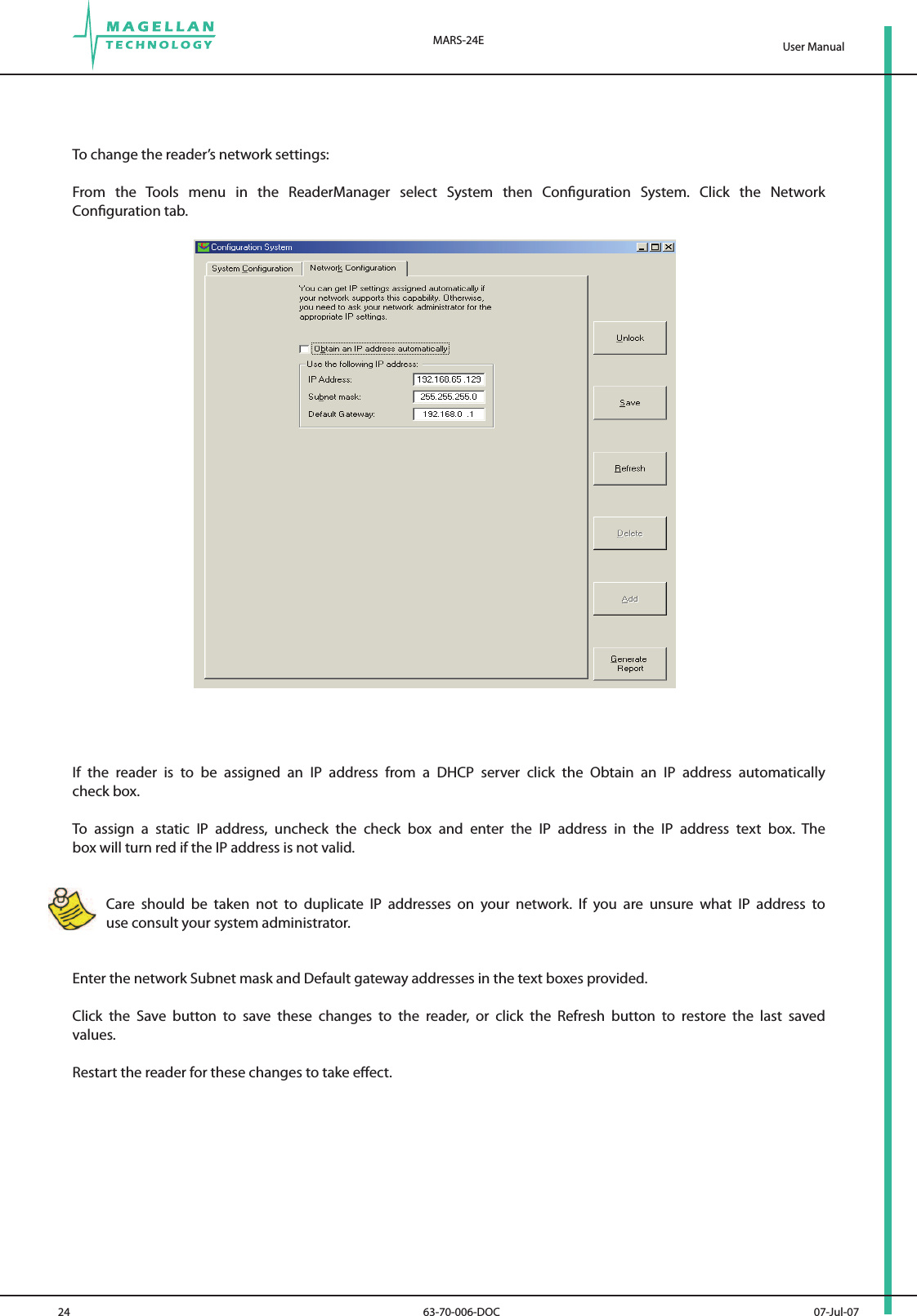
MARS-24E User Manual
>
USERS MANUAL
Contents
1.
USERS MANUAL
2.
MANAGER GUIDE
USERS MANUAL
Navigation menu
Upload a User Manual
Namespaces
Wiki Guide
HTML
PDF
Info
Views
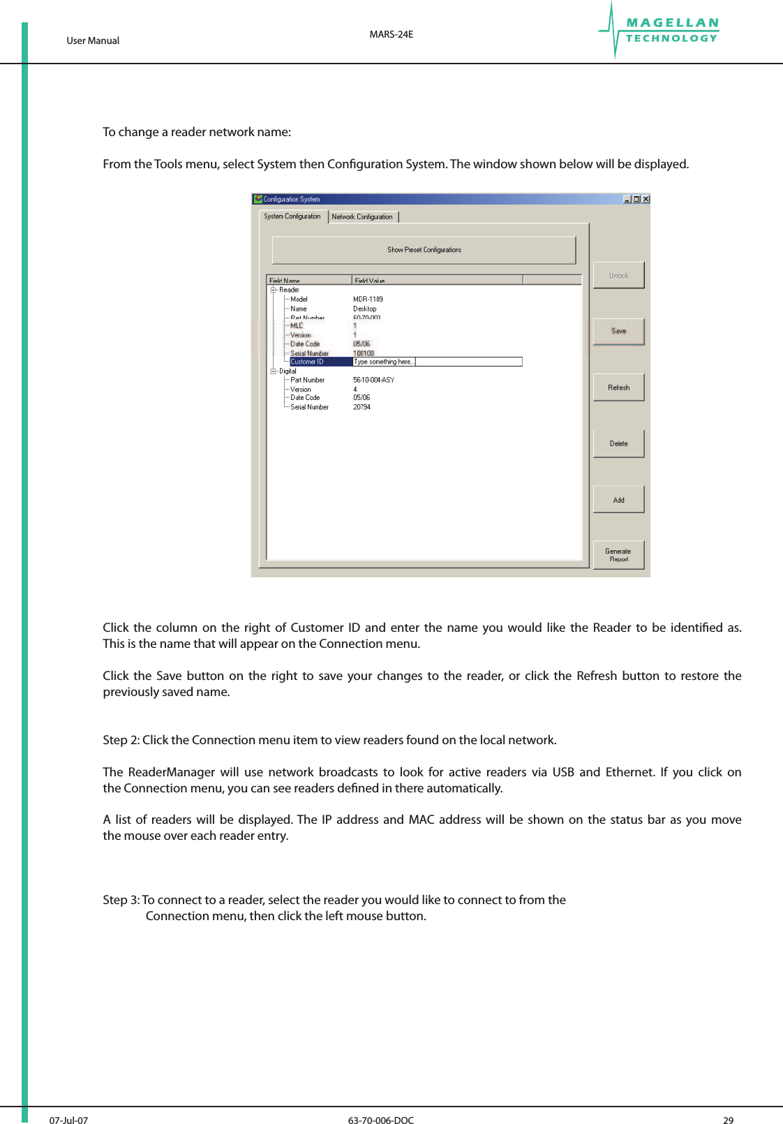
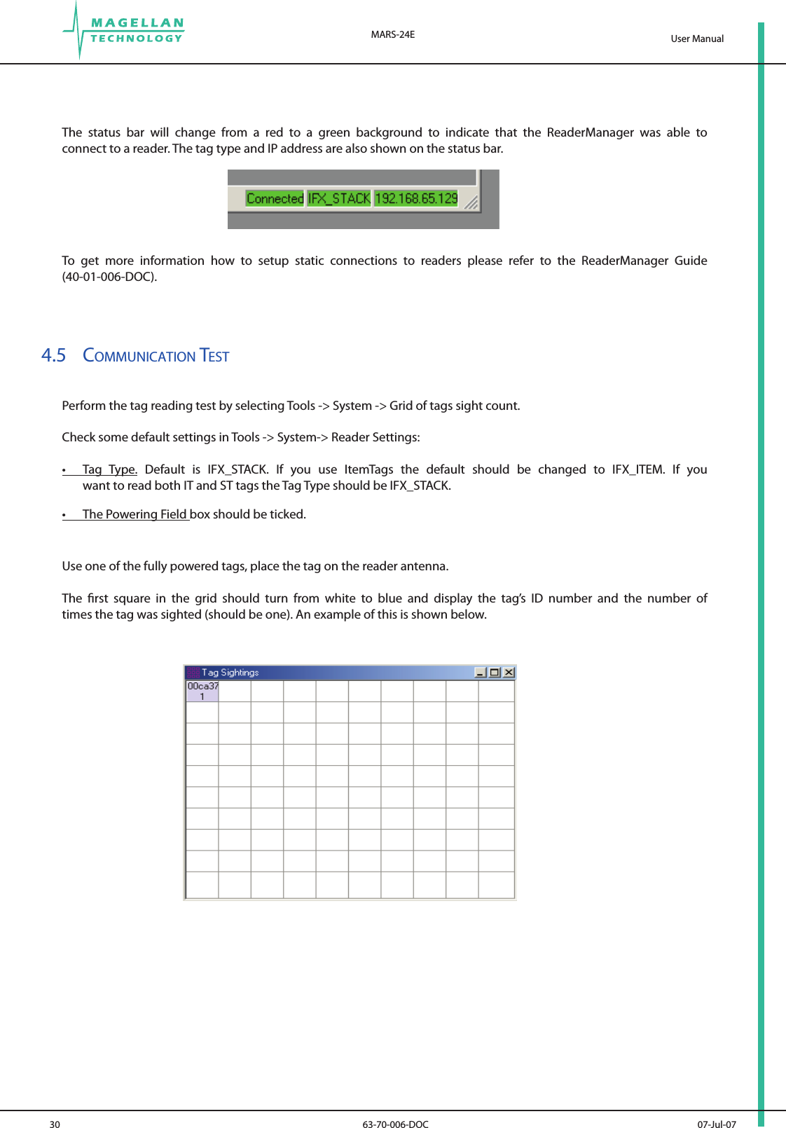
User Manual
Discussion / Help
Navigation