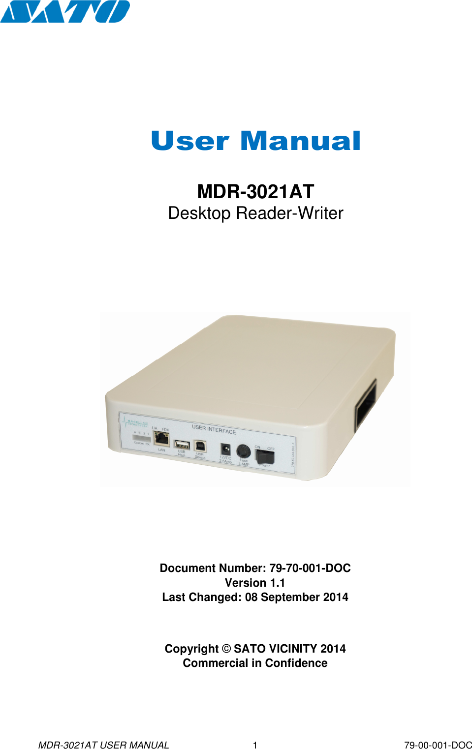
Sato Vicinity MDR-3021AT MDR-3021AT RFID Reader User Manual
Sato Vicinity Pty Ltd MDR-3021AT RFID Reader
UserManual.wiki
>
Sato Vicinity
>
MDR 3021AT User Manual
Users Manual
Navigation menu
Upload a User Manual
Namespaces
Wiki Guide
HTML
PDF
Info
Views
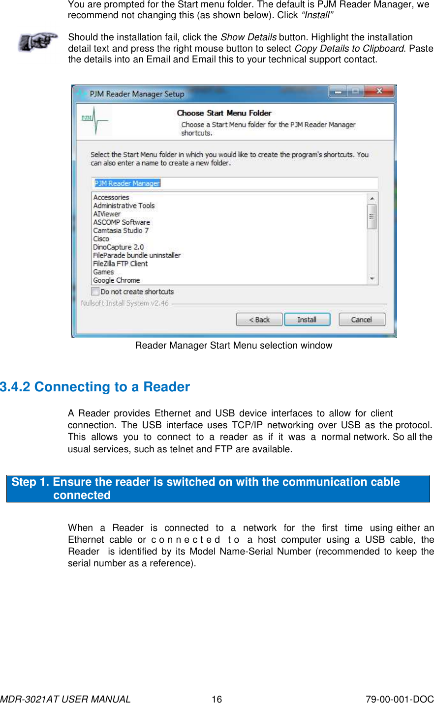
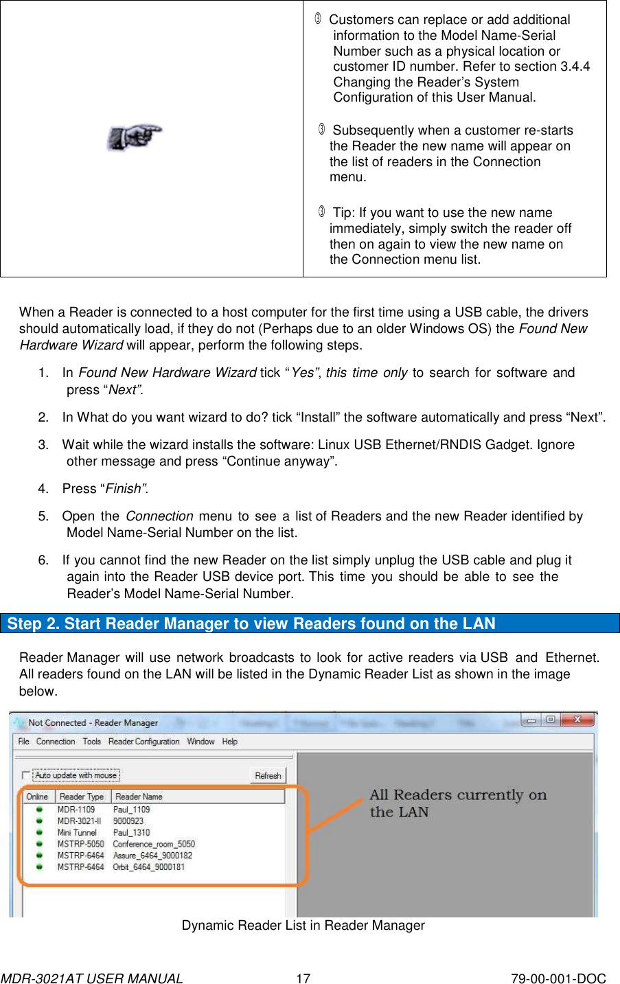
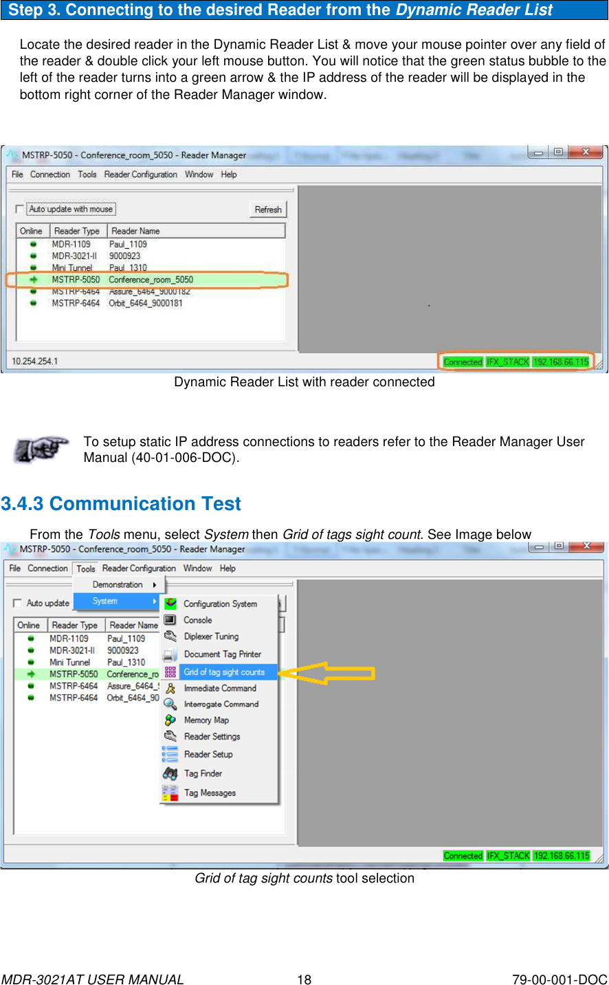
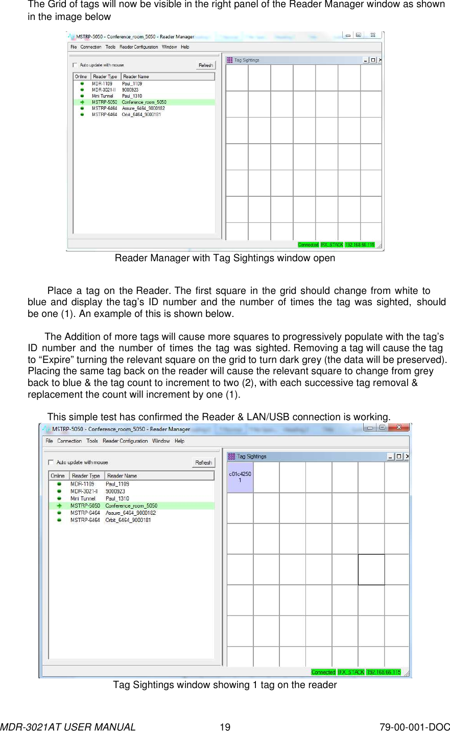
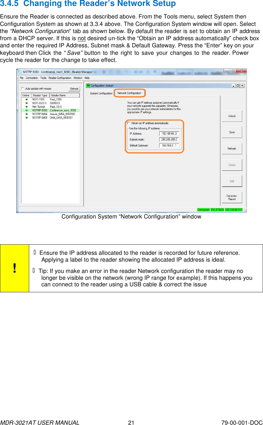
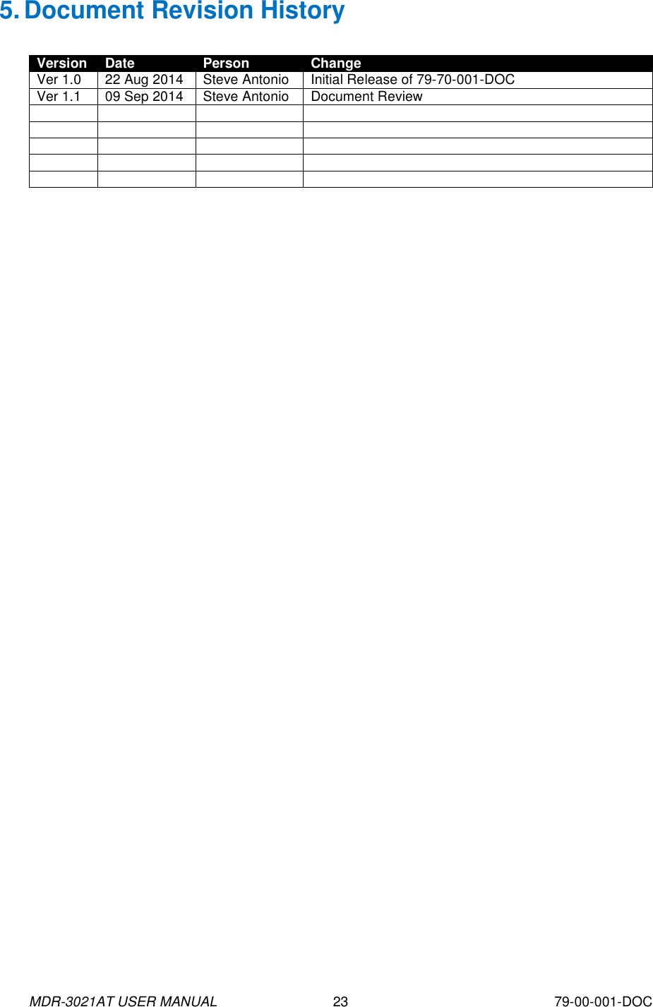
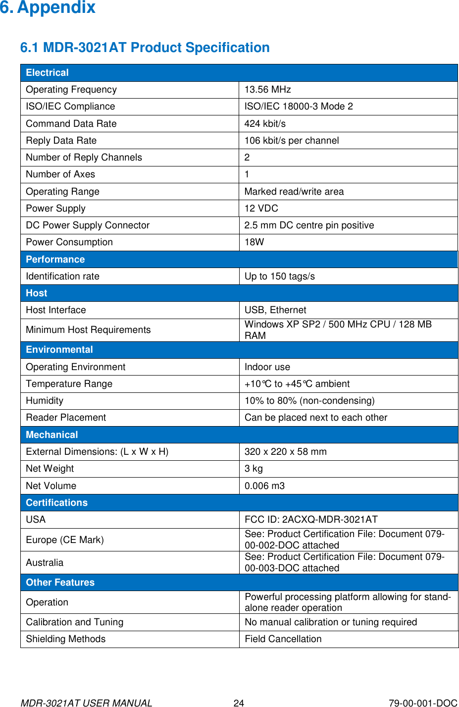
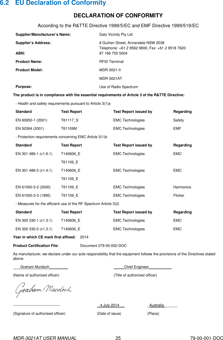
User Manual
Discussion / Help
Navigation