Manual
Barcode Printer
Quick Guide
32
Table of Contents
1. Safety Precautions ........................................................................... 4
Markings and Symbols .......................................................................................... 4
Precautions in Use ................................................................................................. 8
2. Unpacking ..................................................................................... 15
3. Names of Parts .............................................................................. 16
Names and Functions of Operating Parts ............................................................ 18
4. Preparing for First-time Operation ................................................. 19
Charging the Battery Pack ................................................................................... 19
Installing and Removing the Battery Pack ........................................................... 21
Using AC Adapter ............................................................................................... 22
Loading Labels ................................................................................................... 23
• Continuous printing mode ............................................................................ 23
• Dispense mode printing ............................................................................... 25
• Switching from Dispense mode printing to Continuous printing mode .......... 27
5. Turning the Power On .................................................................... 28
6. Test Printing ................................................................................... 29
7. Operation with an RS-232C Cable ................................................ 30
8. Operation with a USB Cable .......................................................... 31
9. Operation via Infrared Communication ......................................... 33
10. Operation with Bluetooth or Wireless LAN Options ...................... 33
11. Printing........................................................................................... 34
12. Troubleshooting ............................................................................. 36
13. Daily Care ...................................................................................... 39
14. Reference ...................................................................................... 41
Included Items ..................................................................................................... 41
Options ................................................................................................................ 41
Operation Modes ................................................................................................. 46
DIP Switch .......................................................................................................... 54
Basic Specifications of MB400i/MB410i .............................................................. 56
Preparation
Preface
Thank you for purchasing the Barcode Printer, MB400i/410i.
This manual is created so that a first-time user of MB400i/410i can learn its basic operations
in a short time.
Please read this manual carefully to make full use of the functions of MB400i/410i.
Cautions
1Reproduction of all or part of this manual is prohibited.
2The content of this manual is subject to change without notice.
3This manual was created with utmost care regarding its content. However, if
you find any unclear points, errors, or omissions, please contact the retail
store or dealer where you purchased this printer.
Cautions regarding radio waves
This product is certified to meet technical standards based on the Radio Law. Therefore,
no wireless license is required to use this printer.
The following actions can be punishable by law:
•Disassembly or modification of this printer
•Removing the certification label (serial label) on this printer
Use in the following locations may drastically shorten the communication distance, or
prevent communication.
•Near a microwave oven; locations where static electricity or radio wave interference is
abundant; near wireless LAN equipment.
“Bluetooth” is a registered trademark of Bluetooth SIG, Inc. USA.
Our company is using this trademark based on a licensing
contract with this association.
Before using the wireless LAN interface, be sure to set all security-related settings for
the wireless LAN equipment according to this manual.
To customers purchasing the Bluetooth or wireless LAN options:
Care
Reference
Troubleshooting
Operation
First Edition 2006. 8. 28 Q01662000
© 2006 SATO Corporation
Safety Precautions
1
5
Safety Precautions
1
4
Liquid
Do not place any container with water or chemicals, such as flower vase or cup, as
well as small metallic objects, near the printer. If any of these should drop into the
printer, immediately turn off the power and contact your nearest dealer or service
center. Continued use creates a danger of fire or electric shock.
Foreign Matter
Do not drop or insert metallic or flammable objects into the openings on the
printer (such as outlets for cables). If any of these should fall into the printer,
immediately turn off the power and contact your nearest dealer or service
center. Continued use creates a danger of fire or electric shock.
Dropping and Damage
Should the printer ever be dropped or otherwise become damaged, immedi-
ately turn off the power and contact your nearest dealer or service center.
Continued use creates a danger of fire or electric shock.
Abnormal Conditions
Continued use of the printer while it is emitting smoke or strange odors creates the
danger of fire or electric shock. Immediately turn off the power and contact your
nearest dealer or service center. Do not try to service the printer by yourself.
Disassembly
Never try to take the unit apart or modify it in any way. Doing so creates the danger of
fire or electric shock. Contact your nearest dealer or service center for checking,
adjustment, or repair.
Battery Pack
•Never try to take apart the battery pack or modify it in any way such as with
a solder iron.
•Never expose the battery to direct flame, throw it into fire, or take any
actions that may lead to shorting.
•When charging the battery pack, make sure to use the printer or the
specified battery charger.
Symbol examples
The triangle indicates something you should take absolute care with. The
cautions are indicated concretely within the symbol. The symbol on the left
indicates a risk of electric shock.
A circle with a diagonal line indicates something you should not do. The
symbol on the left indicates that you should not try to take the unit apart.
A black circle with a picture inside indicates something you need to do. The
symbol on the left indicates that you should unplug the unit from the wall outlet.
1. Safety Precautions
In this section, safety precautions about printer operation are explained to ensure
proper care and usage. Make sure to read these carefully before using your
printer.
Markings and Symbols
The following symbols or markings are used in this manual and on the printer so that you
can properly use the printer, and to prevent any damage to property, harm or injury to
yourself and others. Make sure to read their explanations carefully to familiarize yourself
with their meanings.
This symbol indicates information that, if ignored or applied
incorrectly, creates the danger of death or serious personal injury.
This symbol indicates information that, if ignored or applied
incorrectly, creates the possibility of personal injury or property
damage.
Caution
Warning
Warning
Safety Precautions
1
7
Safety Precautions
1
6
AC Adapter/Battery Charger (Option)
•Use only the specified voltage. Using a different voltage may create the danger of
fire or electric shock.
• Use only the specified AC adapter. Using a different one may create the danger of
fire or electric shock.
• Never use the battery charger with any other battery pack except for the specified
one. Doing so can rupture the battery, cause leakage, fire or electric shock.
• Never cut, damage or modify the power cord. Also, never place heavy objects on
the power cord or heat or pull the power cord. Doing so may damage the cord and
create the danger or fire or electric shock.
• Should the power cord ever become seriously damaged (internal wiring exposed or
shorted), contact your nearest dealer or service center for repair. Continued use of
such a cord creates the danger of fire or electric shock.
• Never modify, excessively bend, twist, or pull the power cord. Doing so creates the
danger of fire or electric shock.
Location
Do not locate the printer in the area subjected to high humidity or dew. If dew forms
inside the printer, immediately turn off the printer and do not use it until it has been
dried up. Continued use creates the danger of electric shock or the printer damage.
Power
•Do not use wet hands to operate the power switch, replace the battery pack or
unplug the AC adapter or battery charger. Doing so creates the danger of electric
shock.
• The AC adapter set provided for this printer is specific to this printer. Do not use it
for other electric equipment.
Thermal Head and Stepping Motor
•The thermal head gets very hot after printing. Take care when replacing the label or
cleaning the printer just after printing to avoid burns.
• Touching the end of the thermal head with bare hands may cause injury. Take care
when replacing the label or cleaning the printer to avoid injury.
• Do not try to replace the thermal head by yourself. Doing so creates the danger of
injury, burns, or electric shock.
Easy Cutter
This part contains a blade. Take care to avoid being injured by the blade and other
sharp parts in the printer.
Replacing the Battery Pack
•Use only the specified battery pack.
• When replacing the battery pack, make sure to install the pack in the correct
orientation. Incorrectly replacing the battery creates the danger of injury or damage
to surrounding areas, explosion is caused.
• Replacing a small-size rechargeable battery (Lithium ion battery)
Apply insulation treatment for the old battery pack by sealing the contact with tape
or the like and ask our sales representative or service center for the measures to be
taken to recycle the reusable materials.
Do not place the battery pack together with other batteries such as dry batteries.
Leaving the printer unused for a long time
If you have no plan to use the printer for a long time, remove the battery pack from
the printer and unplug the AC adapter from the wall outlet.
Maintenance and Cleaning
For safe maintenance or cleaning of the printer, make sure to remove the battery
pack and the AC adapter from the printer.
Caution
Warning

8 9
FCC REQUIREMENT
This device complies with Part 15 of the FCC Rules.
Operation is subject to the following two conditions:
(1) This device may not cause harmful interference, and
(2) This device must accept any interference received,
including interference that may cause undesired operation.
FCC WARNING:
Changes or modifications not expressly approved by the
manufacturer for compliance could void the user's authority to
operate the equipment.
FCC NOTICE:
This equipment has been tested and found to comply with the
limits for a Class B digital device, pursuant to Part 15 of the
FCC Rules. These limits are designed to provide reasonable
protection against harmful interference in a residential
installation. This equipment generates and can radiate radio
frequency energy and, if not installed and used in accordance
with instructions, may cause harmful interference to radio
communications. However, there is no guarantee that
interference will not occur in a particular installation. If this
equipment does cause harmful interference to radio or
television reception, which can be determined by turning the
equipment off and on, the user is encouraged to try to correct
the interference by one or more of the following measures:
-Reorient or relocate the receiving antenna.
- Increase the separation between the equipment and receiver.
-Connect the equipment into an outlet on a circuit different from
that to which the receiver is connected.
-Consult the dealer or an experienced radio/TV technician for
help.
This transmitter must not be co-located or operated in
conjunction with any other antenna or transmitter.
This manual show that both the specification of Bluetooth and
wireless LAN. Please refer to the corresponding section which
shows specification of Bluetooth or wireless LAN.
Wireless LAN specification:
The available scientific evidence does not show that any health
problems are associated with using low power wireless
devices. There is no proof, however, that these low power
wireless devices are absolutely safe. Low power Wireless
devices emit low levels of radio frequency energy (RF) in the
microwave range while being used. Whereas high levels of RF
can produce health effects (by heating tissue), exposure to
low-level RF that does not produce heating effects causes no
known adverse health effects. Many studies of low-level RF
exposures have not found any biological effects. Some studies
have suggested that some biological effects might occur, but
such findings have not been confirmed by additional research.
The MB400i-W2/MB410i-W2 has been tested and found to
comply with FCC radiation exposure limits set forth for
uncontrolled equipment and meets the FCC radio frequency
(RF) Exposure Guideline in Supplement C to OET65. Please
refer to the SAR test report that was uploaded at FCC website.
Bluetooth specification:
This equipment complies with FCC radiation exposure limits set
forth for uncontrolled equipment and meets the FCC radio
frequency (RF) Exposure Guideline in Supplement C to
OET65. This equipment has very low levels of RF energy that is
deemed to comply without testing of specific absorption radio
(SAR).
10 11
Properly shielded a grounded cables and connectors must be
used for connection to host computer and / or peripherals in
order to meet FCC emission limits.
AC adaptor with ferrite core must be used for RF interference
suppression.
CE Caution:
Česky [Czech] [Jméno výrobce] tímto prohlašuje, že tento [typ zařízení] je
ve shodě se základními požadavky a dalšími příslušnými
ustanoveními směrnice 1999/5/ES.
Dansk [Danish] Undertegnede [fabrikantens navn] erklærer herved, at
følgende udstyr [udstyrets typebetegnelse] overholder de
væsentlige krav og øvrige relevante krav i direktiv
1999/5/EF.
Deutsch
[German]
Hiermit erklärt [Name des Herstellers], dass sich das Gerät
[Gerätetyp] in Übereinstimmung mit den grundlegenden
Anforderungen und den übrigen einschlägigen
Bestimmungen der Richtlinie 1999/5/EG befindet.
Eesti [Estonian] Käesolevaga kinnitab [tootja nimi = name of manufacturer]
seadme [seadme tüüp = type of equipment] vastavust
direktiivi 1999/5/EÜ põhinõuetele ja nimetatud direktiivist
tulenevatele teistele asjakohastele sätetele.
English Hereby, [name of manufacturer], declares that this [type of
equipment] is in compliance with the essential
requirements and other relevant provisions of Directive
1999/5/EC.
Español
[Spanish]
Por medio de la presente [nombre del fabricante] declara
que el [clase de equipo] cumple con los requisitos
esenciales y cualesquiera otras disposiciones aplicables o
exigibles de la Directiva 1999/5/CE.
Ελληνική
[Greek]
ΜΕ ΤΗΝ ΠΑΡΟΥΣΑ [name of manufacturer] ∆ΗΛΩΝΕΙ ΟΤΙ
[type of equipment] ΣΥΜΜΟΡΦΩΝΕΤΑΙ ΠΡΟΣ ΤΙΣ
ΟΥΣΙΩ∆ΕΙΣ ΑΠΑΙΤΗΣΕΙΣ ΚΑΙ ΤΙΣ ΛΟΙΠΕΣ ΣΧΕΤΙΚΕΣ
∆ΙΑΤΑΞΕΙΣ ΤΗΣ Ο∆ΗΓΙΑΣ 1999/5/ΕΚ.
Français
[French]
Par la présente [nom du fabricant] déclare que l'appareil
[type d'appareil] est conforme aux exigences essentielles
et aux autres dispositions pertinentes de la directive
1999/5/CE.
Italiano [Italian] Con la presente [nome del costruttore] dichiara che questo
[tipo di apparecchio] è conforme ai requisiti essenziali ed
alle altre disposizioni pertinenti stabilite dalla direttiva
1999/5/CE.
Latviski
[Latvian]
Ar šo [name of manufacturer / izgatavotāja nosaukums]
deklarē, ka [type of equipment / iekārtas tips] atbilst
Direktīvas 1999/5/EK būtiskajām prasībām un citiem ar to
saistītajiem noteikumiem.
Lietuvių
[Lithuanian]
Šiuo [manufacturer name] deklaruoja, kad šis [equipment
type] atitinka esminius reikalavimus ir kitas 1999/5/EB
Direktyvos nuostatas.
Nederlands
[Dutch]
Hierbij verklaart [naam van de fabrikant] dat het toestel
[type van toestel] in overeenstemming is met de essentiële
eisen en de andere relevante bepalingen van richtlijn
1999/5/EG.
Malti [Maltese] Hawnhekk, [isem tal-manifattur], jiddikjara li dan [il-mudel
tal-prodott] jikkonforma mal-ħtiġijiet essenzjali u ma
provvedimenti oħrajn relevanti li hemm fid-Dirrettiva
1999/5/EC.
12 13
Magyar
[Hungarian]
Alulírott, [gyártó neve] nyilatkozom, hogy a [... típus]
megfelel a vonatkozó alapvetõ követelményeknek és az
1999/5/EC irányelv egyéb elõírásainak.
Polski [Polish] Niniejszym [nazwa producenta] oświadcza, że [nazwa
wyrobu] jest zgodny z zasadniczymi wymogami oraz
pozostałymi stosownymi postanowieniami Dyrektywy
1999/5/EC.
Português
[Portuguese]
[Nome do fabricante] declara que este [tipo de
equipamento] está conforme com os requisitos essenciais
e outras disposições da Directiva 1999/5/CE.
Slovensko
[Slovenian]
[Ime proizvajalca] izjavlja, da je ta [tip opreme] v skladu z
bistvenimi zahtevami in ostalimi relevantnimi določili
direktive 1999/5/ES.
Slovensky
[Slovak]
[Meno výrobcu] týmto vyhlasuje, že [typ zariadenia] spĺňa
základné požiadavky a všetky príslušné ustanovenia
Smernice 1999/5/ES.
Suomi [Finnish] [Valmistaja = manufacturer] vakuuttaa täten että [type of
equipment = laitteen tyyppimerkintä] tyyppinen laite on
direktiivin 1999/5/EY oleellisten vaatimusten ja sitä
koskevien direktiivin muiden ehtojen mukainen.
Svenska
[Swedish]
Härmed intygar [företag] att denna [utrustningstyp] står I
överensstämmelse med de väsentliga egenskapskrav och
övriga relevanta bestämmelser som framgår av direktiv
1999/5/EG.
Íslenska [Icelandic] Hér með lýsir [name of manufacturer] yfir því að [type of
equipment] er í samræmi við grunnkröfur og aðrar kröfur,
sem gerðar eru í tilskipun 1999/5/EC.
Norsk
[Norwegian]
[Produsentens navn] erklærer herved at utstyret [utstyrets
typebetegnelse] er i samsvar med de grunnleggende krav
og øvrige relevante krav i direktiv 1999/5/EF.
If you want to get a copy of the original Declaration of Conformity
of our products which relates the R&TTE, please contact to web
address: www.satoworldwide.com
Safety Precautions
1
14
Unpacking
2
15
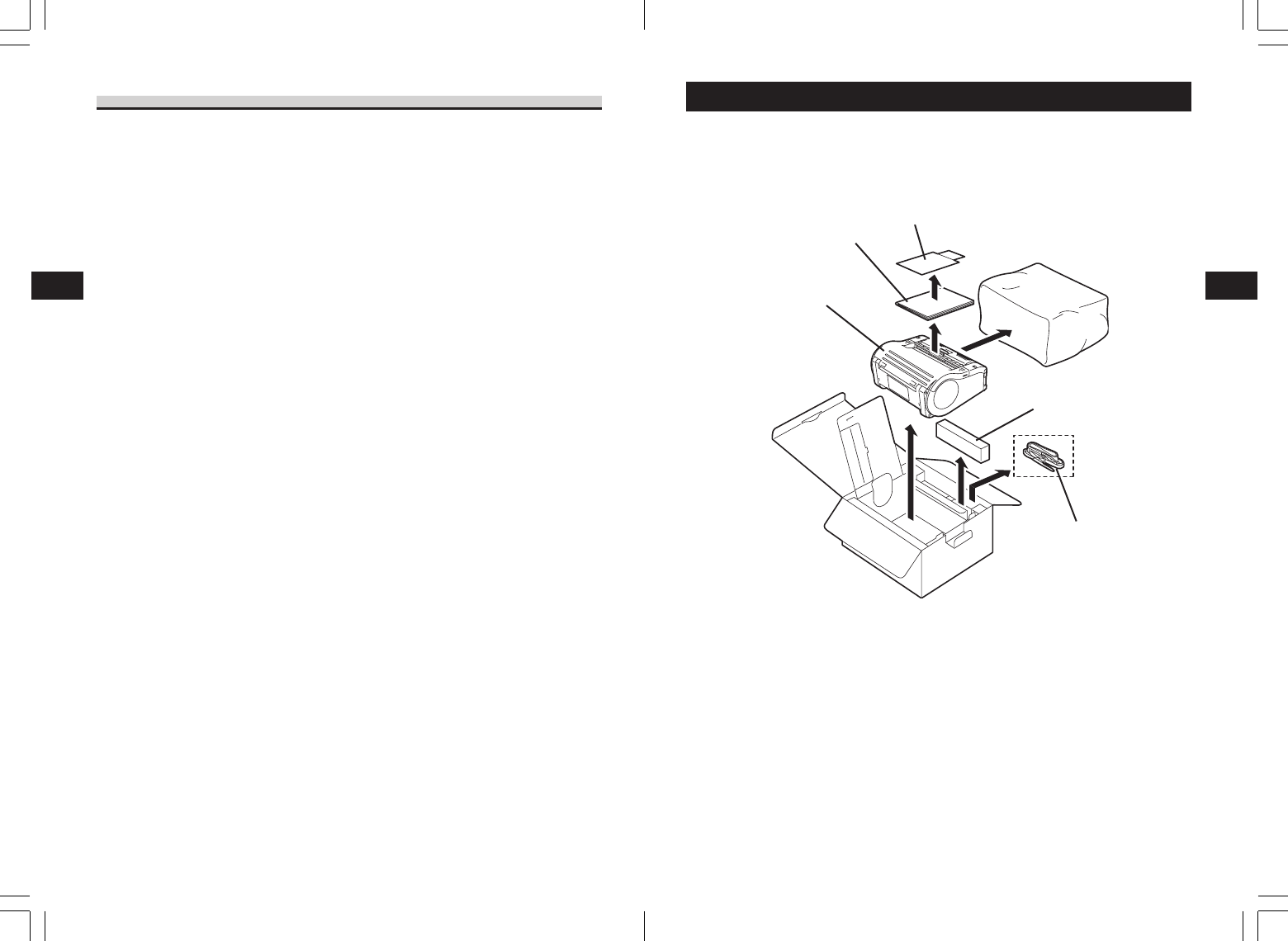
2. Unpacking
Make sure you have all the printer components shown here. If any component is
missing, contact the retail store or dealer where you purchased the product from.
Warranty
Quick Guide
Printer unit
Battery pack
*The appearance of any cushioning material supplied (such as protector pads on the
printer holder) may be changed across different production batches.
Shoulder belt
Precautions in Use
Do not place the printer in a hot or cold place.
The operation temperature range is -15°C to 50°C (for wireless LAN: 0 to 50°C) where
humidity does not cause condensation. Do not place the printer in an area with high
humidity or at a temperature outside the specified range.
Do not drop or apply undue shock to the printer.
The printer is generally resistant to vibration possibly caused during normal
transportation. However, do not apply extreme vibration or shock by dropping the printer.
Do not disassemble or modify the printer.
The printer has high-precision components inside requiring fine adjustment. Do not
disassemble the printer.
Connect the correct cables to the external input terminals.
Cables of the correct specifications are required for connection to the external equipment
through the external input terminals. Contact your nearest dealer or service center if
necessary.
Use the recommended accessories.
Using optional equipment other than the specified equipment may cause a malfunction.
Always use the equipment specified in this guide.
Use the correct media.
Use the specified media. Otherwise, faulty printing or printer damage may occur.
Names of Parts
3
17
Names of Parts
3
16
234
4
D
1
ON
110
100
90
80
70
60
*1Only provided on wireless LAN interface operating panel (manufacturer option). For
other options, see “Options” on page 35.
*2On a wireless LAN interface operating panel (manufacturer option), a CHARGE LED is
provided.
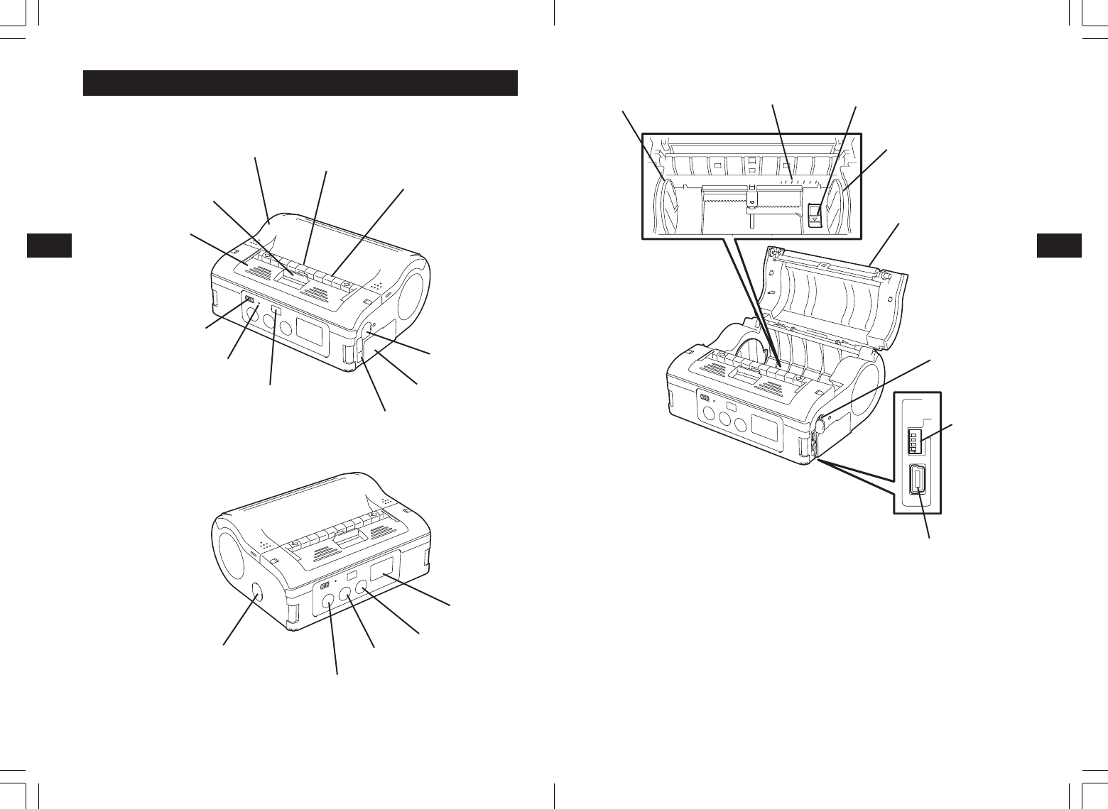
Label guide
Label width scale
Platen
POWER button
Label guide stopper
LCD *1
DIP switch
Infrared communication sensor
PRINT button
FEED button
STATUS (LED)
USB connector
Battery life indicator
(LED) *2
RS-232C connector
3. Names of Parts
Easy cutter
Main cover
Cover release lever
Dispenser unit
RS-232C cover
DC input terminal cover
Battery cover
Label dispenser
Label guide
USB/DIP switch cover
Names of Parts
3
18
Preparing for First-time Operation
4
19
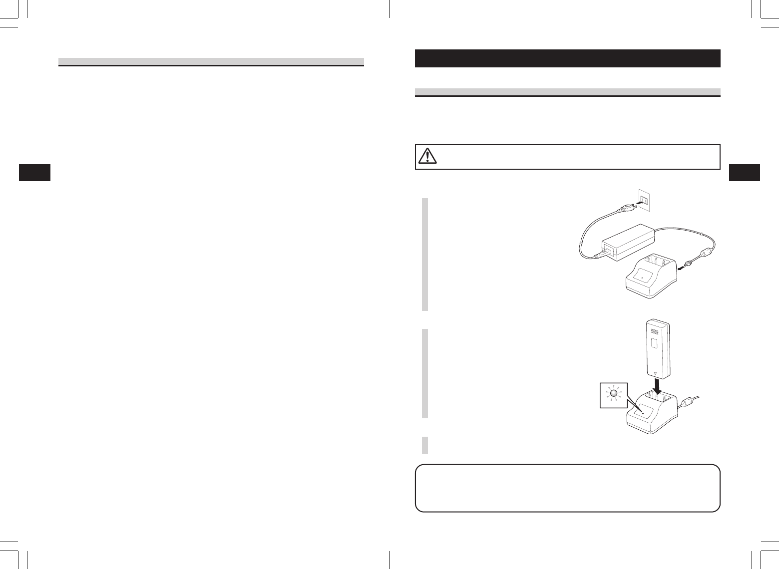
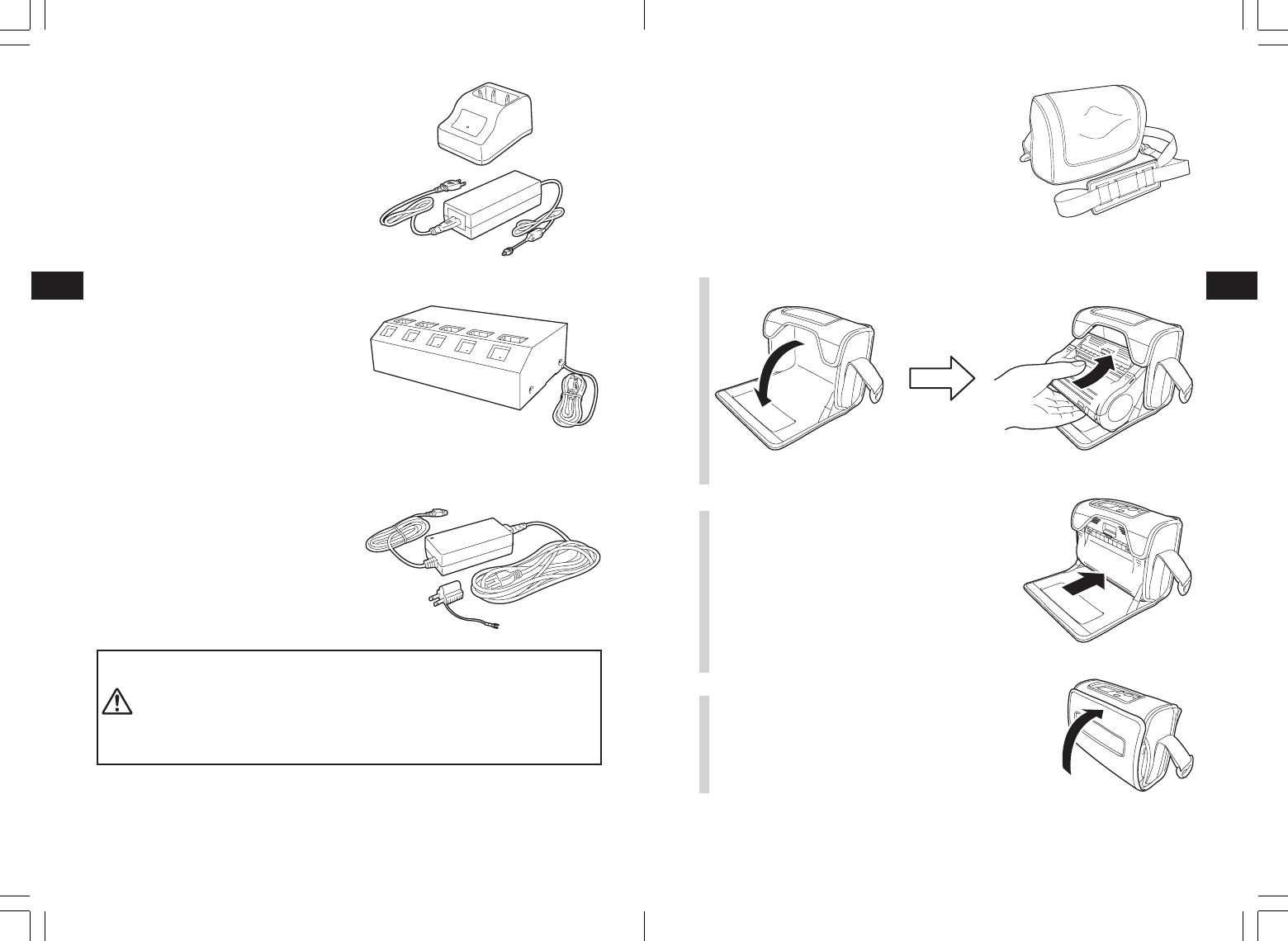
1Connect the power cord to the
charger unit, then plug it into the
outlet.
•When charging is complete, the
CHARGE lamp lights green (fully
charged).
4. Preparing for First-time Operation
Charging the Battery Pack
• Charging by installing the battery pack in the battery charger (optional)
Install the battery pack in the battery charger (optional) and charge it.
CHARGE
The optional battery charger set provided for this printer is specific to this printer.
Do not use it for other electric equipment.
Charging time
It takes about 1.5 hours for the CHARGE lamp to turn off when charging a completely
depleted battery.
Names and Functions of Operating Parts
RS-232C cover:
This covers the RS-232C connector.
RS-232C connector:
Connects with a PC etc.
USB/DIP switch cover:
Covers the USB connector and DIP
switch.
USB connector:
Connects with a PC etc.
Main cover:
Open this cover to set the labels.
Cover release lever:
Use this to release the main cover.
Easy cutter:
Cuts the printed label.
Infrared communication sensor:
Contains an infrared receiver/transmitter
element.
DIP switch:
Sets the operation mode. (See P. 48)
Dispenser unit:
Move this when using Dispense mode
printing for the labels.
POWER button:
Turns the power on and off.
Battery cover:
A specialized battery pack is placed
inside.
Battery life indicator (LED):
Displays the available battery power.
Label guide:
Set this to match the size of the label
width used.
Label guide stopper:
Press this toward the back to unlock the
label guide and adjust the label guide.
Label dispenser:
Printed labels are ejected here.
Label width scale:
Use this scale to match the label width
used.
DC input terminal:
Connect the AC adapter.
DC input terminal cover:
Cover for the DC input terminal.
FEED button:
Feeds the labels.
PRINT button:
Takes the printer ONLINE and OFFLINE.
STATUS (LED):
Displays the printer status. (See P. 30-31
and 41-47)
2Insert the battery pack. Insert the
battery pack into the slot, with
the terminal pointing downward.
•When charging begins, the
CHARGE lamp (red) lights. When
charging is complete, the CHARGE
lamp lights green (fully charged).
3Remove the battery pack when
charging is complete.
Preparing for First-time Operation
4
21
Preparing for First-time Operation
4
20
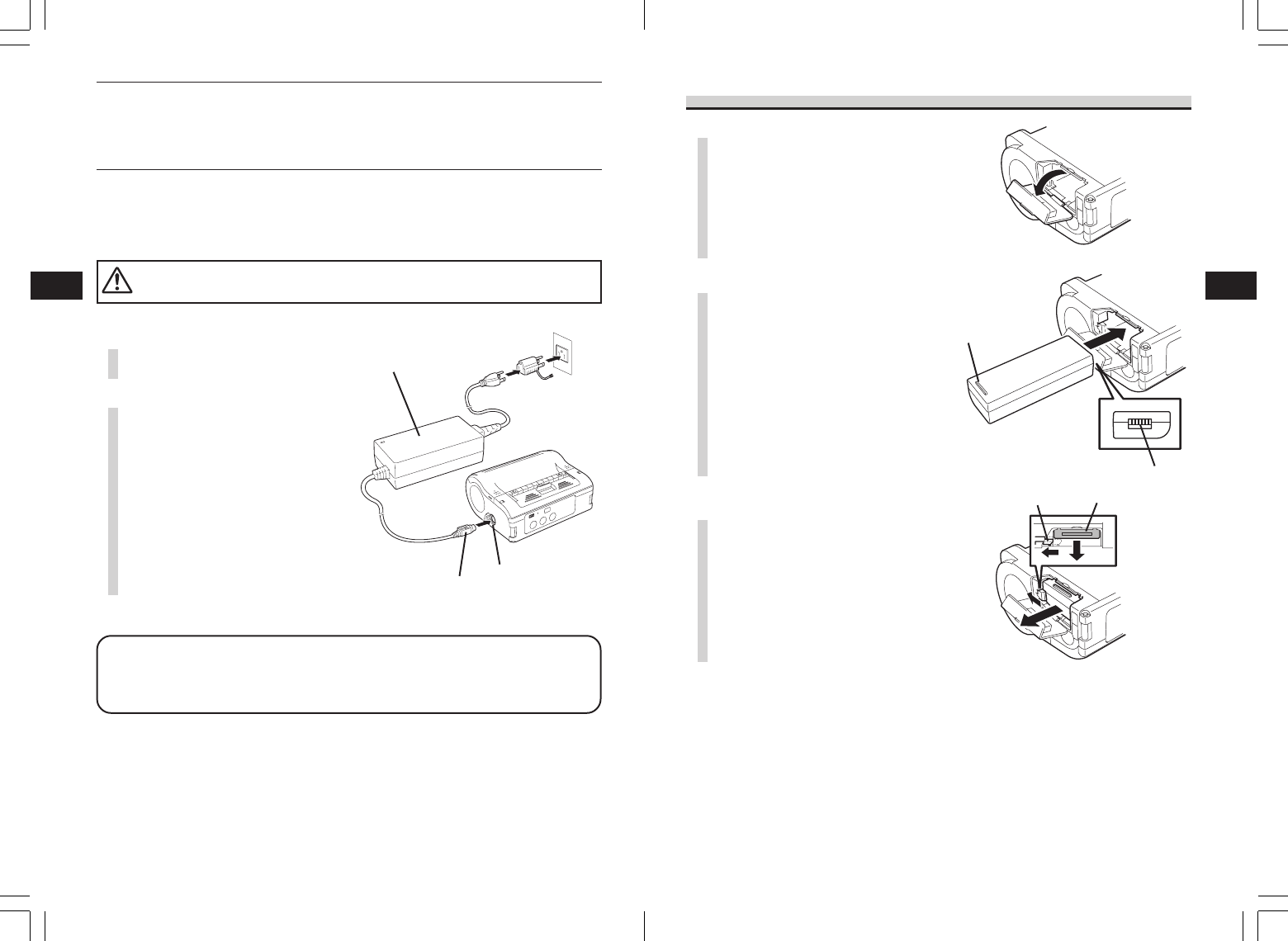
Installing and Removing the Battery Pack
Battery pack
Hook
Terminal
Handle
Charging time
It takes about 5 hours for the battery remaining power display to turn off when
charging a completely depleted battery.
1Remove the DC input terminal
cover, and insert the DC output
terminal.
• Charging by installing the specialized AC adapter (optional) on the printer
This charges the battery pack while it is installed in the printer.
DC output terminal
AC adapter
DC input terminal
The AC adapter set provided for this printer is specific to this printer. Do not use it
for other electric equipment.
Note
•When the CHARGE lamp is not lit, check that the battery pack is installed securely.
The battery may not be charged when not securely installed.
•When a charged battery pack is installed, the CHARGE lamp first lights red, then lights
green.
2Plug the AC adapter into the
outlet.
When charging begins, the battery life
indicator lights red. When charging is
complete, the battery life indicator
disappears (fully charged).
*On a wireless LAN interface
operating panel (manufacturer
option), the CHARGE LED lights
red when charging begins. When
charging is complete, the CHARGE
LED turns off (fully charged).
1Open the battery cover.
2While pressing the gray hook,
insert the battery pack, then
close the battery cover.
Insert the battery pack with the terminal
side toward the printer.
3To remove the battery, press the
gray hook to unlock it, then hold
the handle and pull out the
battery.
* Be sure to turn the power off before removing or replacing the battery
pack.
When the power is off, the STATUS LED turns off (see “Power OFF” on
page 22). Do not remove the battery pack until this light turns off.
Make sure to check that the STATUS LED has turned off before
removing the battery pack.
*Note that removing the battery pack by the operation above may
prevent updating the information in the printer memory.
Preparing for First-time Operation
4
23
Preparing for First-time Operation
4
22
1Remove the DC input terminal
cover, and insert the DC output
terminal into the input terminal.
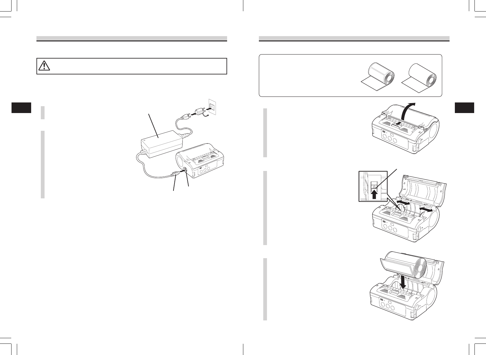
Loading Labels
The label installation method differs by printing mode.
Continuous printing mode
Label paper Journal paper
(See figure on P. 40)
Label guide stopper
Using AC Adapter
Install the specialized AC adapter (optional) on the printer for use.
The AC adapter set provided for this printer is specific to this printer. Do not use it
for other electric equipment.
• Use AC ADAPTER: Model No. TG-5001-19v
DC output terminal
AC adapter
DC input terminal
2Connect the AC adapter into the
outlet.
* Be sure to turn the printer power off before detaching the DC output
terminal for the AC adapter, or disconnecting the power supply.
Note that disconnecting the power supply in ways other than described
above may prevent the printer from correctly storing any settings in
memory.
No battery pack is necessary when the AC adapter is used. When the
battery pack and AC adapter are used simultaneously, charging begins if
the battery is not fully charged. The display becomes normal when fully
charged (See P. 14).
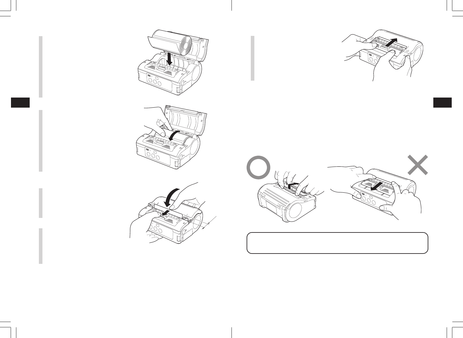
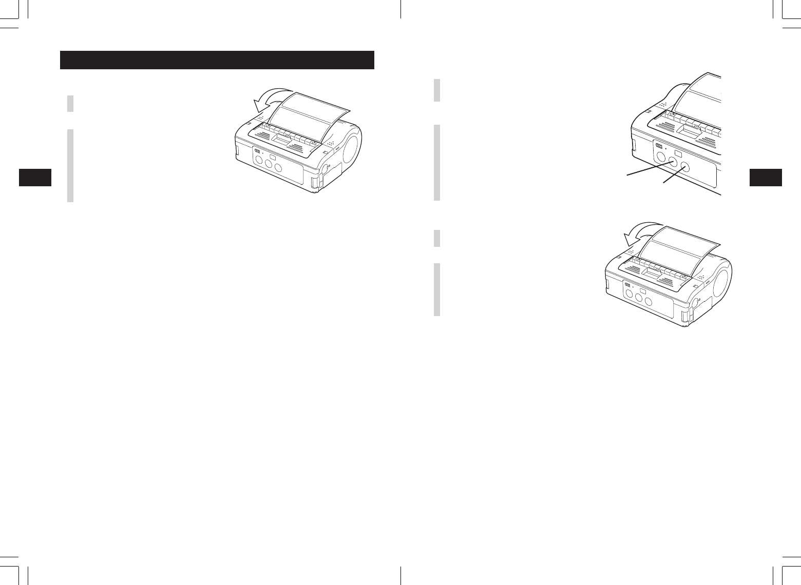
1Slide the cover release lever in
the arrow direction to open the
cover.
First, slide the dispenser unit to the
continuous printing mode position.
(See P. 21)
2While pressing the label guide
stopper, slide the label guide to
the label size to be used.
3Load the paper in the printer.
Make sure the roll is oriented correctly.
Preparing for First-time Operation
4
25
Preparing for First-time Operation
4
24
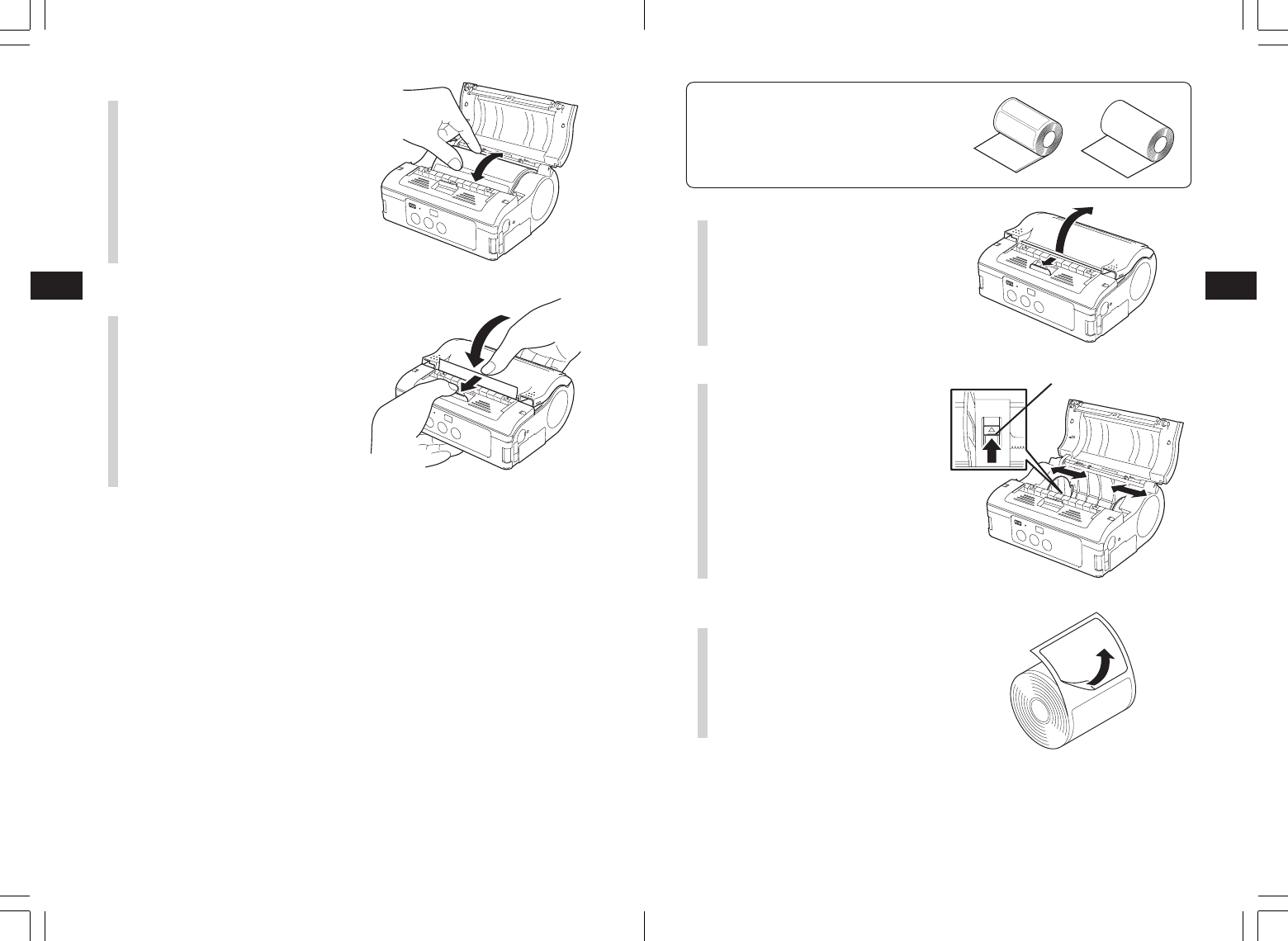
Dispense mode printing
Label paper Non-separated labels
(See figure on P. 40)
Label guide stopper
5Check that the label tip is
protruding. Then close the main
cover by pressing the middle of
the cover.
Close the main cover slowly, while
pulling the cover release lever.
4Confirm that the label roll can be
rotated easily by hand.
If rotation is labored, this can cause a
feed error. Remove the label roll and
adjust the label guide. Note that the
label guides do not require adjustment
when you are using labels with the
same width.
This completes loading the labels for continuous printing mode.
1Slide the cover release lever in
the arrow direction to open the
cover.
First, slide the dispenser unit to the
continuous printing mode position. (See
P. 21)
*Never slide the dispenser unit while
the main cover is open.
2While pressing the label guide
stopper, slide the label guide to
the label size to be used.
3Peel the label at the tip of the
label paper.
Dispense mode printing is not required
for non-separated labels.
Preparing for First-time Operation
4
27
Preparing for First-time Operation
4
26
10mm
8Slide the dispenser unit until it
stops.
4Load the paper in the printer.
Make sure the roll is oriented correctly.
5Confirm that the label roll can be
rotated easily by hand.
If rotation is labored, this can cause a
feed error. Remove the label roll and
adjust the label guide. Note that the
label guides do not require adjustment
when using labels with the same width.
6Check that the label tip is
protruding (10 mm or more).
Then close the main cover by
pressing the middle of the cover.
Close the main cover slowly, while
pulling the cover release lever.
7For non-separated labels, press
the FEED button to feed one
sheet, and pull upward to tear
along the perforated line.
If the labels clog at the label dispenser,
restart the label loading process from
the beginning.
This completes loading of the labels for dispense mode printing.
•Switching from Dispense mode printing to Continuous printing mode
Holding the dispenser/continuous switching lever upward, slide the dispenser unit toward
you. Never pull it with the lever still engaged. This may damage the dispenser unit.
When using dispense mode printing, be sure to follow the procedure above to switch
the dispenser unit from dispense mode printing to continuous printing mode, before
changing the paper.
Turning the Power on
5
28
Test Printing
6
29
6. Test Printing
POWER
PRINT
FEED
1
2
1234567
ABCDEFG
abcdefg
1234567
ABCDEFG
abcdefg
2Verify the following using the
output of the test print.
•
There are no chipped characters.
•Printing condition is good.
In test printing, the estimated
remaining battery power is
displayed as “
”. (
when
completely charged.) When the
remaining battery power is
,
charge the battery.
5. Turning the Power On
When the preparation steps are complete, turn the power on or off.
POWER
PRINT
FEED
POWER
PRINT
FEED
*If a problem occurs, contact the retail store or dealer where you purchased the printer
from, or our sales personnel or service center.
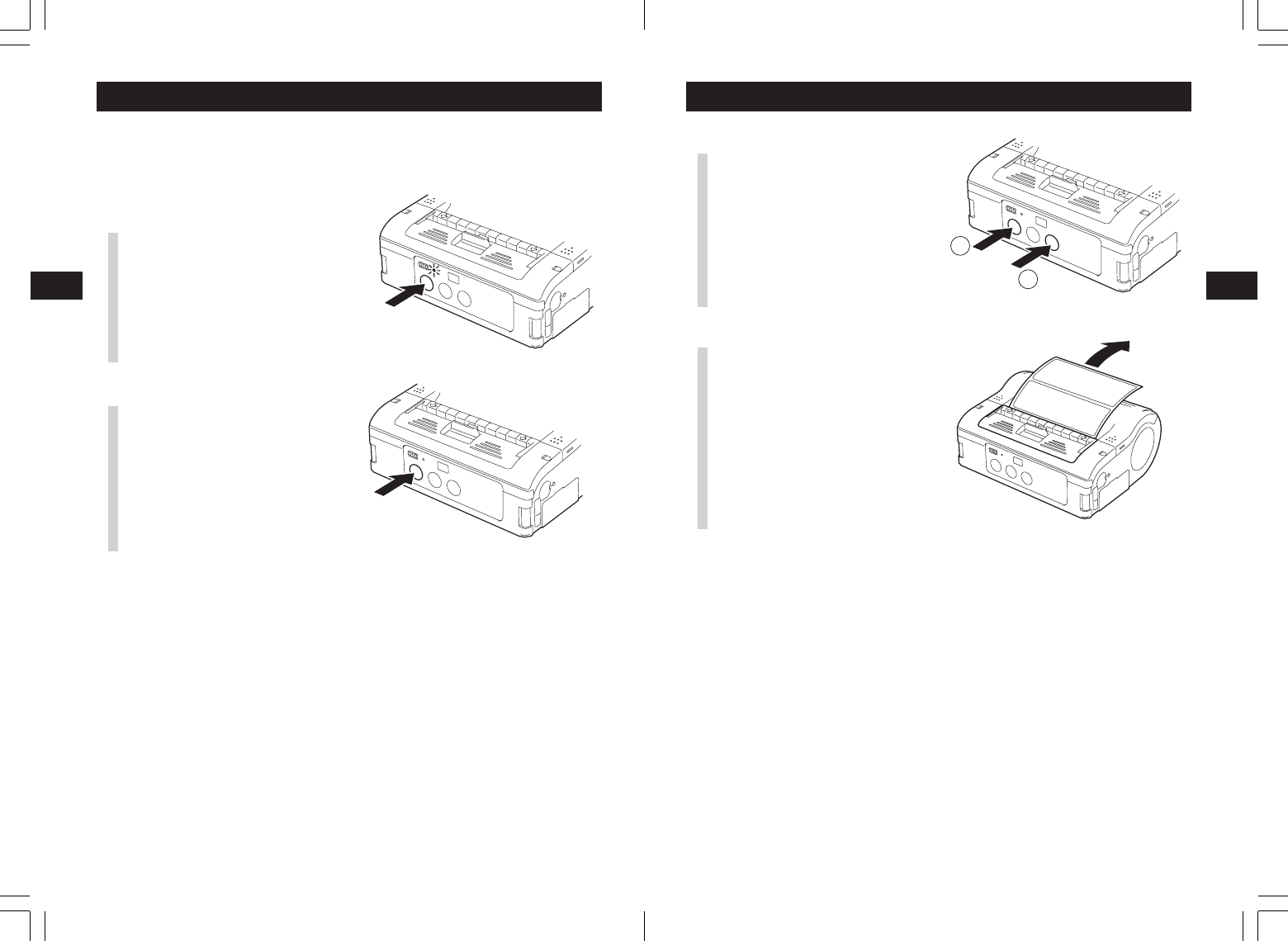
1When pressing the FEED button
and holding down the POWR
button simultaneously, the printer
enters the test mode. Press the
FEED button again to start test
printing.
Power ON
1Hold down the POWER button
until the STATUS LED lights
green. Then release the POWER
button.
Power OFF
2Hold down the POWER button
again, until the STATUS LED
turns off. Then release the
POWER button.
Operation with an RS-232C Cable
7
30
Operation with a USB Cable
8
31
4Connect the other end of the
RS-232C cable to the connector
on the PC or the handheld
terminal.
For the connector on the PC or the
handheld terminal, see the manuals
provided with that equipment.
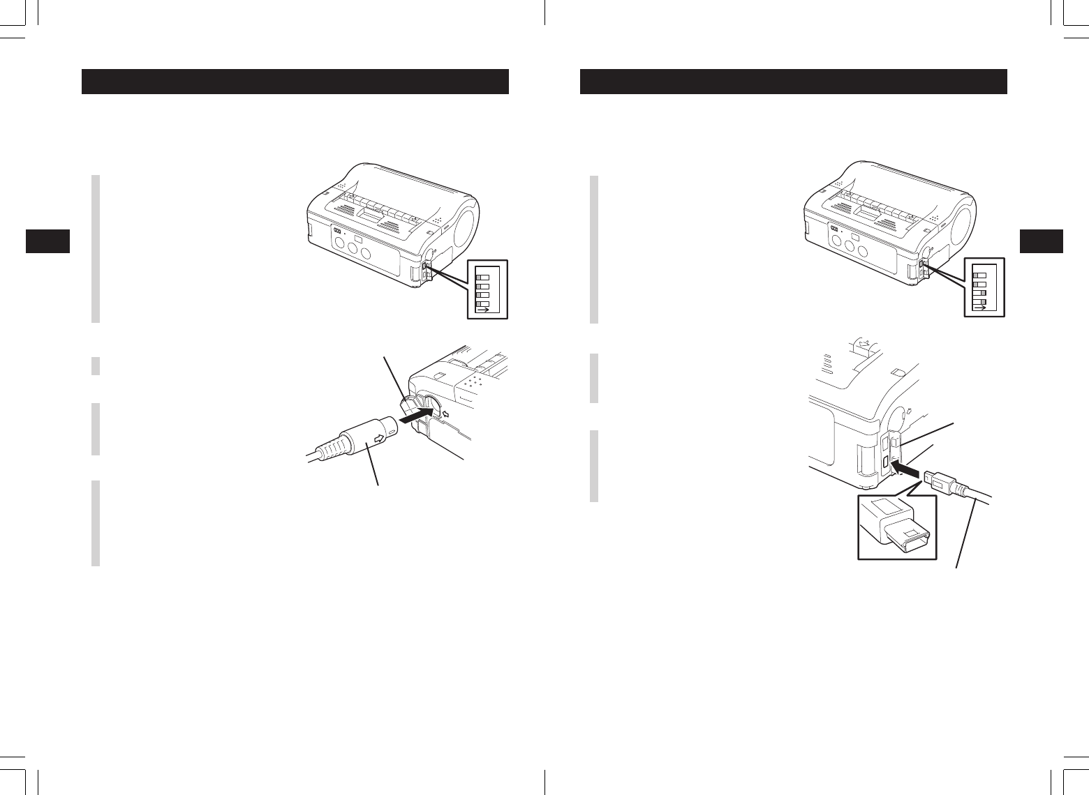
3Insert the RS-232C cable into
the connector.
Match the arrow on the RS-232C cable
connector with the arrow beside the
printer connector, and insert it firmly.
2Remove the RS-232C connector
cover.
7. Operation with an RS-232C Cable
To print with an optional RS-232C cable connected to a PC or a handheld
terminal, perform the following operations.
1Remove the USB/DIP switch
cover, and set the DIP switch
(DSW) to DSW-1, 2, 3, 4 = (OFF,
OFF, OFF, OFF).
2341
ON
RS-232C cable
3Connect the other end of the
USB cable to the connector on
the PC or the handheld terminal.
For the connector on the PC or the
handheld terminal, see the manuals
provided with that equipment.
8. Operation with a USB Cable
To print with an optional USB cable (mini B type) connected to a PC or a
handheld terminal, perform the following operations.
1Remove the USB/DIP switch
cover, and set the DIP switch
(DSW) to DSW-1, 2, 3, 4 = (ON,
ON, OFF, OFF).
2Insert the USB cable into the
connector.
Match the arrow on the USB cable
connector with the arrow beside the
printer connector, and insert it firmly.
2341
ON
USB cover
USB cable
RS-232C cover
Operation via Infrared Communication
9
32
Operation with Bluetooth or Wireless LAN Options
10
33
10.
Operation with Bluetooth or Wireless LAN Options
To print using a Bluetooth interface or a wireless LAN interface, perform the
following operations.
9. Operation via Infrared Communication
To print using infrared communication, perform the following operations.
30°
30°
2341
ON
2341
ON
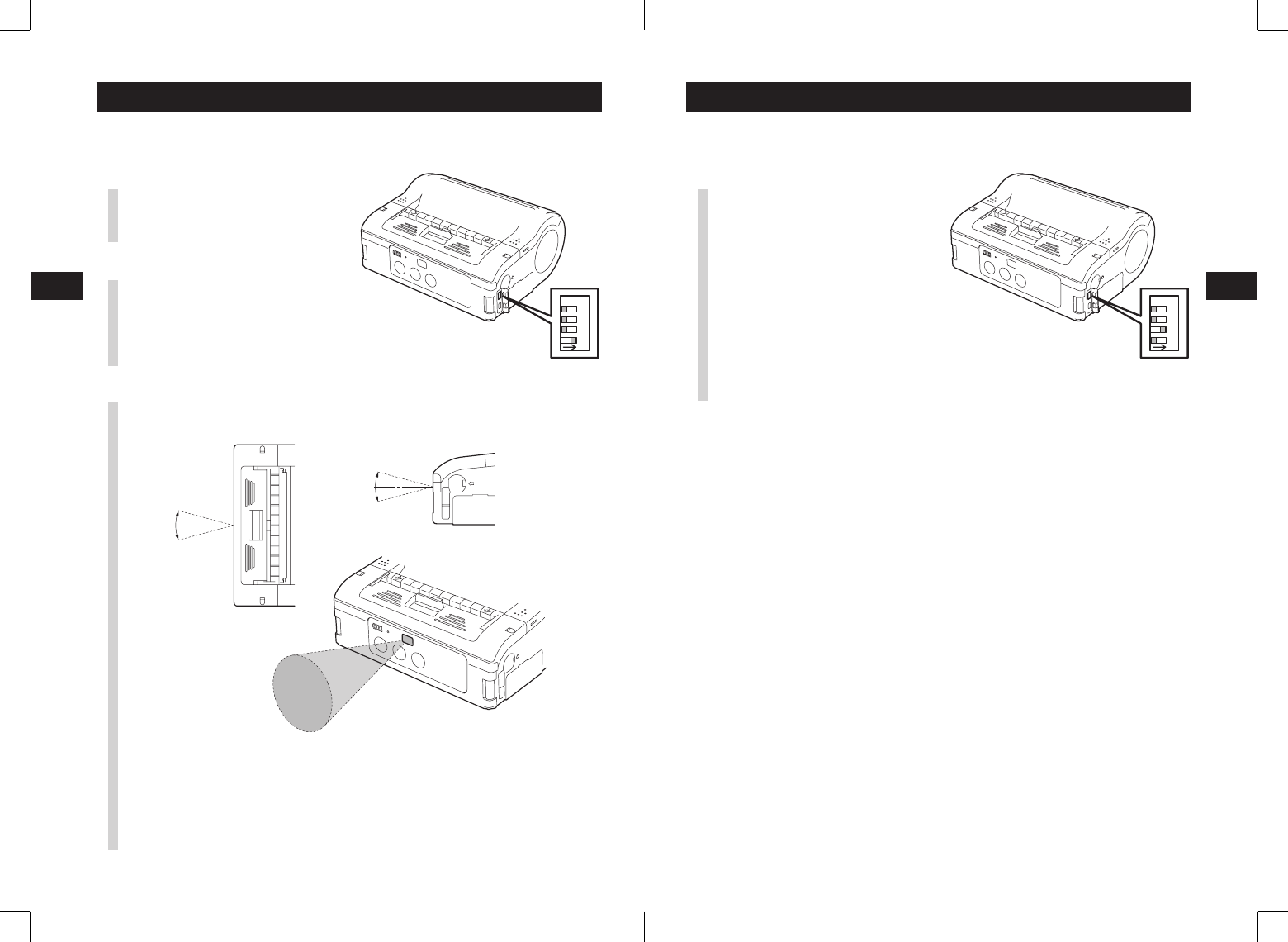
2Place the printer within 20 cm of
the PC or handheld terminal for
infrared communication.
1Remove the USB/DIP switch
cover, and set the DIP switch
(DSW) to DSW-1, 2, 3, 4 = (ON,
OFF, OFF, OFF).
3Adjust the printer position so that the PC or handheld terminal is within a
30° area vertically and horizontally (cone shape) from the center of the
infrared communication sensor.
The maximum usage distance for infrared communication is 15 to 20 cm.
*
However, this differs with the usage environment and the communicating
equipment. Communication may not be possible in direct sunlight or
under powerful illumination. In such cases, either shield the infrared
communication sensor from harsh light, or place the infrared
communication sensor in contact with the communicating equipment.
1Remove the USB/DIP switch
cover, and set the DIP switch
(DSW) to DSW-1, 2, 3, 4 = (OFF,
ON, OFF, OFF).
*Note that the effective distance varies with the usage environment,
computer, or handheld terminal in use.
Printing
11
35
Printing
113
34
■When the next label is not printed
12345
67
ABCDEF
G
abcdefg
1
A
BC
ab
cd
FEED button
PRINT button
1234567
ABCDEFG
abcdefg
1234567
ABCDEFG
abcdefg
11
.Printing
1234567
ABCDEFG
abcdefg
1234567
ABCDEFG
abcdefg
1Data is sent from a PC.
2When printing is complete, hold
the right or left corner of the
label, pull it in the direction of the
arrow, and tear the label.
*The number of labels that can be printed with one battery pack differs between
continuous printing mode and dispense mode printing.
*When the non-separated labels are severed somewhere other than the perforated line,
and the next label is not printed, perform the operations on page 29.
1With the printer online, press the
PRINT button to take the printer
offline (STATUS LED turns off).
2Press the FEED button to feed
the labels.
3When the paper stops, pull it in
the direction of the arrow to cut
the label.
4Press the PRINT button to put
the printer online (STATUS LED
lights green).
Troubleshooting
12
37
Troubleshooting
12
36
* : Contact your nearest service center or retail store.
12
.Troubleshooting
The status of this printer is indicated by the STATUS LED display and a buzzer
sound. When the STATUS LED display or buzzer indicates the status below, the
STATUS LED/buzzer
LED: ON (red)
LED: Blinking (red) every 2 seconds
Buzzer: One long beep
LED: ON (red)
LED: Two colors blinking alternately
(green ➝ red) every 2 seconds
Buzzer: One long beep
LED: Blinking (red) every 0.5 seconds
Buzzer: Three short beeps
LED: Blinking (green) every 1 second
Buzzer: One long beep
LED: Blinking (green) every 0.5
seconds
Buzzer: One long beep
LED: Blinking (red) every 4 seconds
Buzzer: One long beep
LED: Blinking (green) every 2 seconds
LED: Patterned lighting (red ➝ OFF ➝
green ➝ OFF) every 1 second
LED: Two colors blinking alternately
(green ➝ orange) every 0.5 seconds
Content
Low battery
Module error (Bluetooth or
wireless LAN)
1 Program abnormality
error
2 FLASH ROM error
Head error
Cover open
Out of paper
Sensor error
Communication error
Buffer almost full
Buffer overflow
Sleep mode
Head overheating protection
function
Manual dispensing mode
Mode
All modes
Online
After turning power on
Online
Online
Online
Online (printing or
receiving data)
Online (printing or
receiving data)
All modes
All modes
Online (automatic
dispenser printing or
dispenser operation 2)
Cause
1 The battery is not fully charged.
1 Interface module is in abnormal condition.
(Bluetooth or wireless LAN)
1 A FLASH ROM reading/writing error has
occurred.
1 The head has a broken wire.
1 The cover is not locked.
2
Cover opening/closing sensor is in abnormal condition.
1 Out of labels.
1 The sensor level is incorrect.
2 The sensor type is incorrect.
3 The paper is misrouted.
1
The communication conditions are incorrect.
2
Cable connection is in abnormal condition.
1 The receiving buffer is running out of
capacity.
1 Data has exceeded the receiving buffer
capacity.
2 The communication conditions are
incorrect.
1 This is not an error.
The printer is operating in low power
consumption mode.
1 This is not an error.
The head overheating protection function operates
when the head temperature exceeds 70°C.
1 This is not an error.
2 Press the PRINT button to print one label.
Clearing method
1 Charge the battery.
1 Replace the board.*
1 Replace the FLASH ROM.*
2 Re-download the program.*
1 Replace the head.*
1 Lock the cover.
2 Adjust the sensor.*
1 Set a new roll of label.
1 Adjust the sensor level.*
2 Match the sensor type.
3 Remove the label roll and place it correctly.
1 Correct the communication conditions.
2 Check the cable connections.
1 Pause host data transmission, wait for the
buffer to empty, then retransmit data.
1 Transmit data corresponding with the
communication conditions.
2 Correct the communication conditions.
1 Clear by pressing a button, receiving data,
or opening/closing the main cover.
1 This is cleared when the head temperature
falls to 55°C.
1 Automatically cleared when the designated
number of labels are printed.
printer is in an abnormal condition. Clear the error using the clearing method.
The printer will automatically turn off in about 30 seconds after a low battery
display appears. Confirm that the power is off, then remove the battery pack and
charge it.
Troubleshooting
12
38
Daily Care
13
39
13
. Daily Care
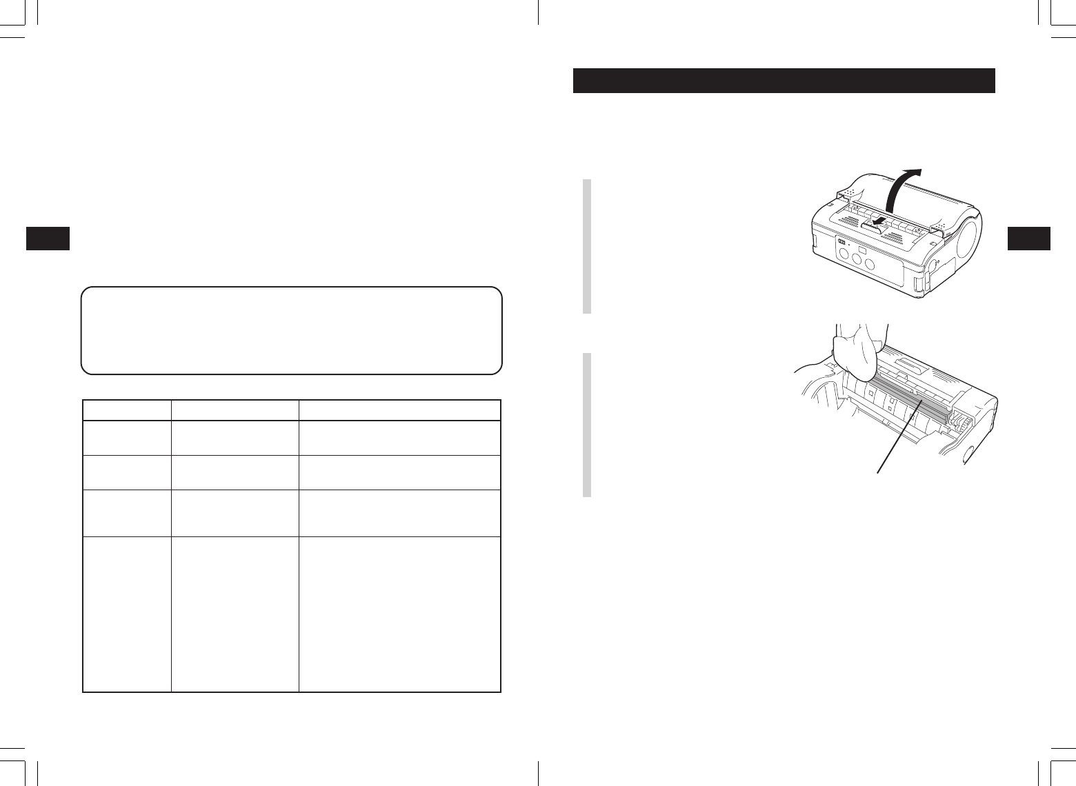
Be sure to turn the power off and remove the battery pack before performing the
following operations.
■Caring for the thermal head
2Wipe off any smudges with a
cloth dipped in alcohol.
*Do not use thinner, benzene, or
kerosene.
Dispenser roller
Print condition
Smudged
Vertical stripes
Characters
printed diagonally
Blank
(not printed)
Cause
1 The head is dirty.
2 The rollers are dirty.
1 The head is dirty.
2 The head is defective.
1 The label guide position
is incorrect.
2 The rollers are dirty.
1 The RS-232C/USB
cable connection is
poor.
2 Infrared communication
error.
3 Bluetooth/wireless LAN
communication error.
4 The DIP switch settings
are incorrect.
5 The head is defective.
Countermeasures
1 Clean the head (See P. 33).
2 Clean the platen (See P. 34).
1 Clean the head (See P. 33).
2 Replace the head.*
1 Reset the label (See P. 17).
2 Clean the platen (See P. 34).
1 Check the RS-232C/USB cable
connections (See P. 24 and 25).
2
The distance between the PC and the
printer should be within 15-20 cm. In
addition, check that the PC is within a
30° area vertically and horizontally (cone
shape) from the center of the printer
infrared communication sensor (See P. 26).
3 Check all settings.
4 Check the DIP switch settings
(See P. 48).
5 Replace the head.*
* : Contact your nearest service center or retail store.
■When printing fails (automatic printing)
In direct sunlight or under illumination, the internal sensors may mis-operate (assuming
a label is present in the dispenser unit), and prevent printing. In such malfunction, either
shield the dispenser unit from harsh light, or operate using one of the following
methods.
1Operation using manual printing
Switch to manual printing by specifying the dispenser operation mode.
(See P. 43)
2Operate using operation 2 for the dispenser operation
Using the printer setup tool, switch the dispenser operation to operation 2.
When operation 2 is set for the
dispenser
operation, if harsh light is preventing
printing, print using the following procedure.
Press the PRINT button to switch to manual printing, and print one label. When printing
multiple labels, operate with manual printing until the designated number of labels are
printed.
While operating in manual printing mode, the STATUS LED alternates between lighting
green and orange (every 0.5 seconds).
1Slide the cover release lever to
open the cover.
When in dispense mode printing, first
slide the dispenser unit to the
continuous printing mode position. (See
P. 21)
Daily Care
13
40
Reference
14
41
Platen
Paper sensor
14
.Reference
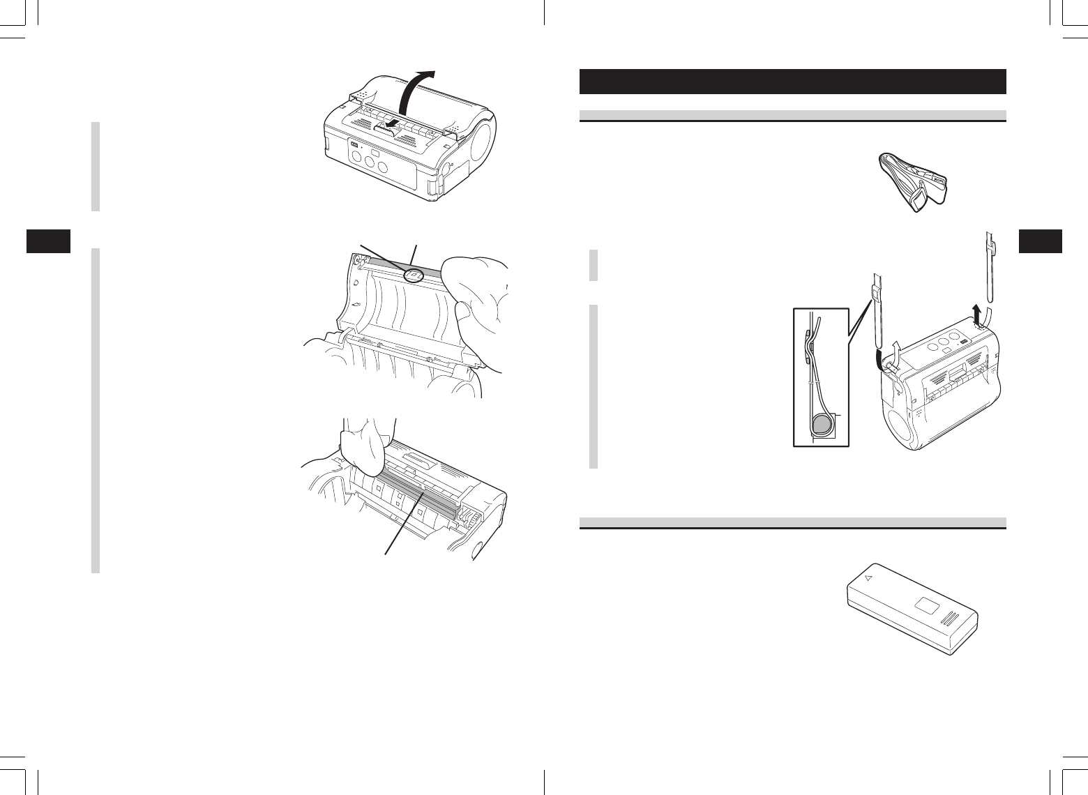
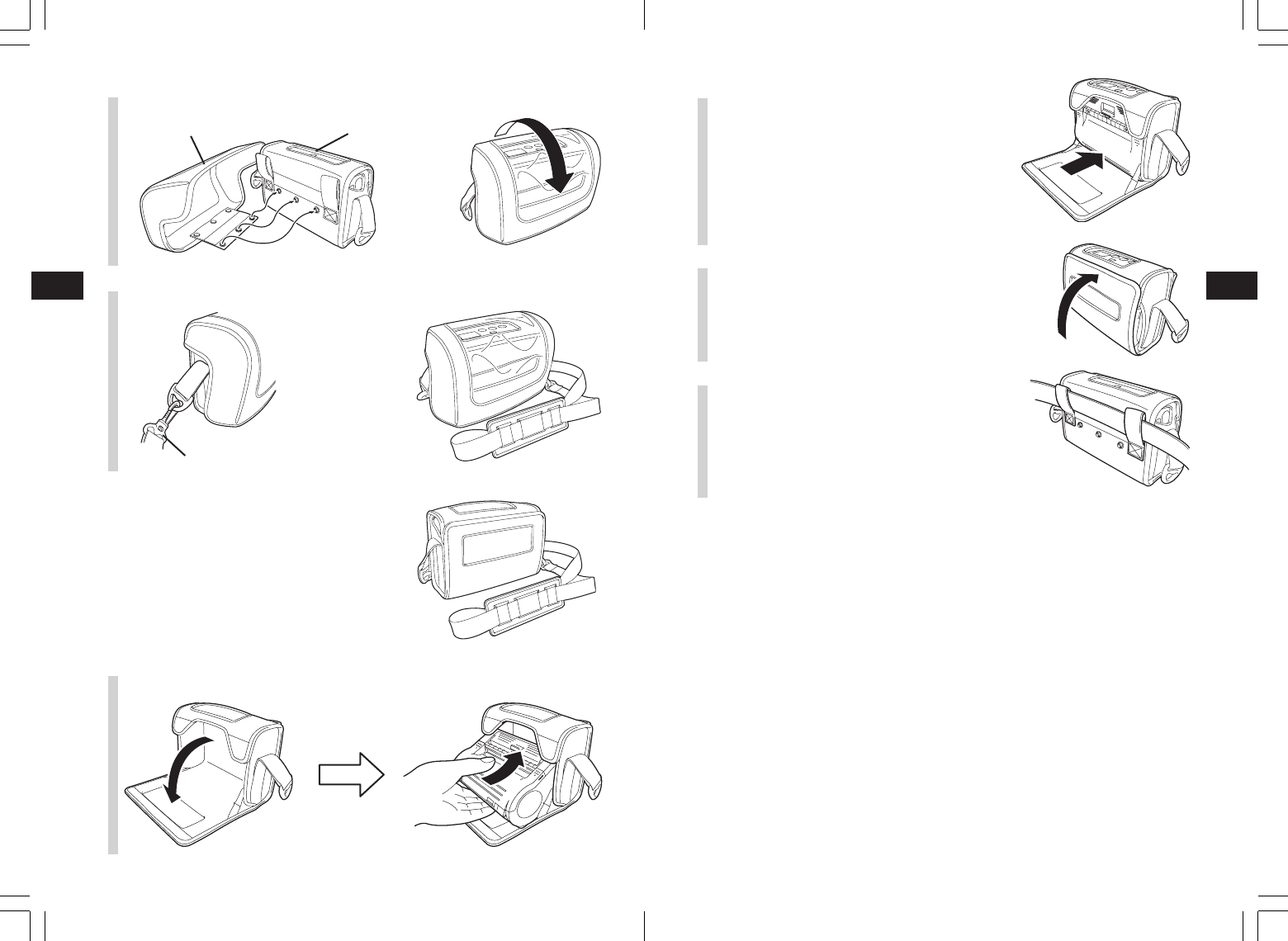
Included Items
• Shoulder belt
This belt allows you to carry the printer on your
shoulder.
1Thread the shoulder belt through
the belt holes on the printer, from
the outside to the inside.
2Thread the end of the shoulder
belt through the buckle, and
adjust the length.
*If the belt is not routed correctly, the
belt may detach and the printer may
drop.
■Caring for the platen/
dispenser roller/paper sensor
Dispenser roller
1Slide the cover release lever to
open the main cover.
When in dispense mode printing, first
slide the dispenser unit to the
continuous printing mode position. (See
P. 21)
2Wipe off any smudges with a
cloth dipped in alcohol.
*Do not use thinner, benzene, or
kerosene.
Options
User options
•Battery pack (one pack provided with this
printer)
Having extra batteries available will
minimize work interruptions caused
by depleted batteries.
Reference
14
43
Reference
14
42
•Be sure to use the specified adapter.
•Hold the printer when connecting or disconnecting.
•Be careful not to damage the cord.
•Unplug for storage when not in use.
•The AC adapter set provided for this printer is specific to this printer. Do not use
it for other electric equipment.
•AC adapter for printer
Use this to supply power from a
household power outlet (AC100V or
240V).
Connect the DC output terminal of
the AC adapter to the printer.
•Battery charger (single)
This charges a single battery pack.
•Battery charger (quintuple)
This charges multiple battery packs
(maximum of five).
•Shoulder case with rainproof cover
This is a version of the Belt case that has a rainproof
cover.
Fastening method
1Open the cover and place the printer in with the operating parts facing up.
2Place the lower side in the case
so that the printer is completely
in the case.
3Close the cover.
Reference
14
45
Reference
14
44
•RS-232C cable
This connects with a PC or handheld terminal.
• USB cable
This connects with a PC or handheld terminal.
Manufacturer options
•Wireless LAN interface operating panel (with LCD)
This is an operating panel with an LCD to display the wireless communication
status.
4Affix the rainproof cover to the Belt case with the buttons and set in place. 2Place the lower side in the case
so that the printer is completely
in the case.
3Close the Belt case cover.
4Run a belt through the Belt case.
Fastening method
1Open the cover and place the printer in with the operating parts facing up.
5Attach the shoulder strap to the rainproof case.
•Belt case
This protective case is for carrying the printer
by attaching it to your belt.
Shoulder strap
Rainproof cover Belt case

Reference
14
47
Reference
14
46
Normal operation mode
Power saving mode
PRINT
button PRINT
button
FEED button Feed paper
POWER
1. Sleep mode:
With the printer online, the STATUS (LED) blinks (green) every two seconds. When
offline, the STATUS (LED) is off. The battery life indicator (LED) remains on even
when the printer is OFFLINE.
The printer enters sleep mode (standby status) when it has not been operated for five
seconds.
Normal status is resumed by pressing the PRINT button or the FEED button, by
receiving data, or by opening and closing the main cover.
POWER ON
The LED display for the normal operation mode is as follows.
Operation status STATUS (LED)
Starting normal printing mode ON (orange)
Online ON (green)
Offline OFF
* When the buzzer sound mode is enabled, the buzzer sounds upon startup.
The battery life indicator remains on even when the printer is OFFLINE.
Online
Offline
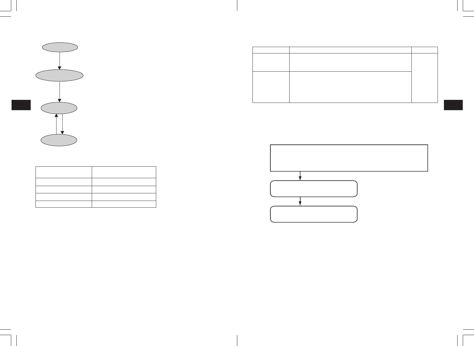
Operation Modes
There are two printer operation modes: continuous printing mode, and dispense
mode printing. Test printing and online printing are available in both modes.
*Use the printer setting tool to set dispense mode printing (non-separated labels).
1234567
ABCDEFG
abcdefg
1234567
ABCDEFG
abcdefg
1234567
ABCDEFG
abcdefg
1234567
ABCDEFG
abcdefg
Continuous printing Dispenser printing
(label paper)
Dispenser printing
(non-separated labels)
Test printing
Continuous printing
Dispenser printing
Online printing
Continuous printing
Dispenser printing
Prints the printer status
(Receives data from a PC or
handheld terminal and prints it)
Reference
14
49
Reference
14
48
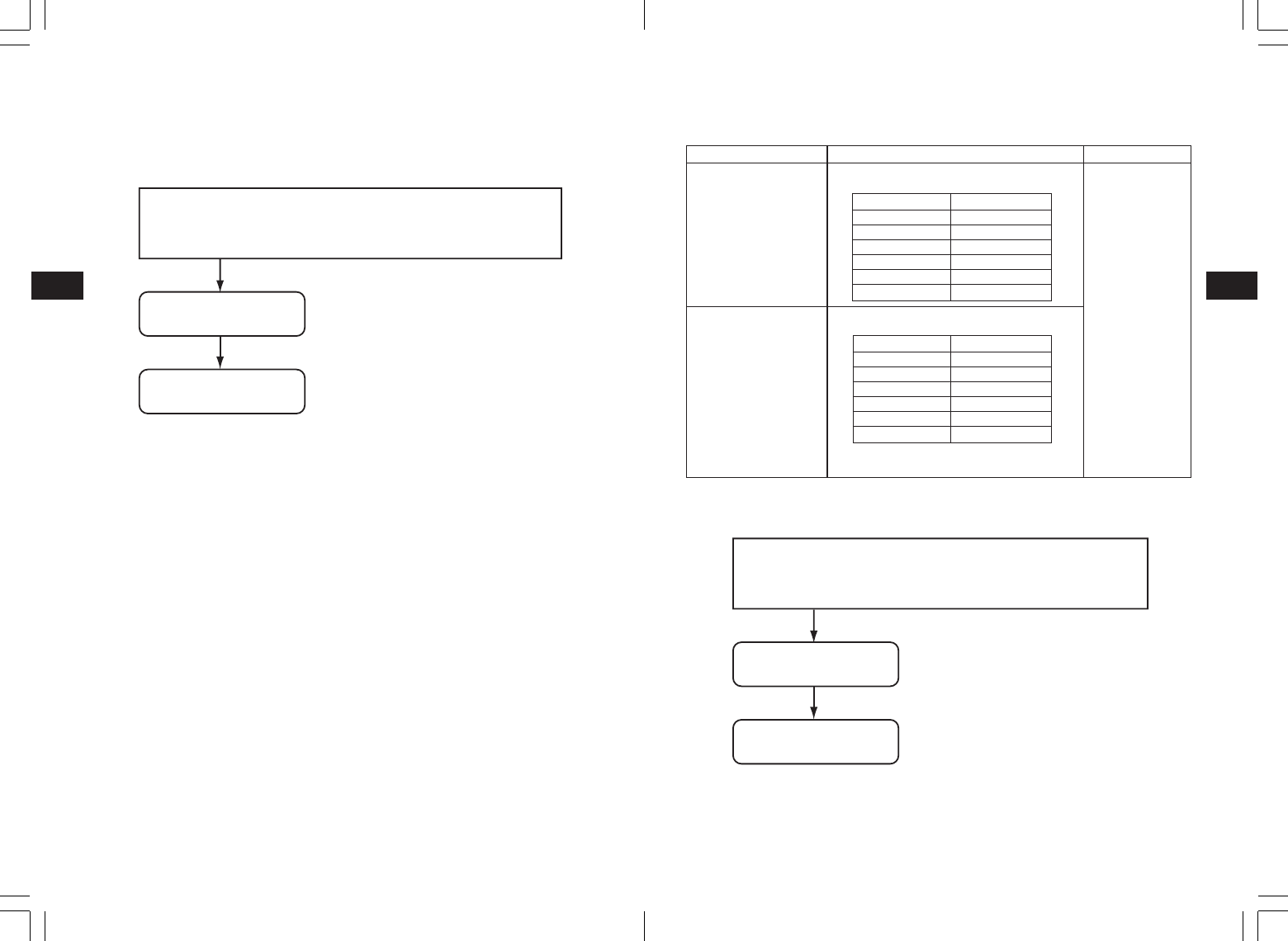
Dispense mode printing
Dispense mode printing setting
Changing the dispense mode printing setting
The
dispenser
operation mode setting is changed by the DIP switch (DSW) settings when the
power is turned on, and by
button
settings. The settings are enabled upon turning the power
off.
Type
Automatic
printing setting
Manual printing
setting
Operation
Prints one label after receiving data, then waits for label to
be peeled. After the label is peeled, the next label is
printed automatically.
Prints one label after receiving data, then enters offline
status. When the PRINT button is pressed, the next label is
printed. After the specified number of labels are printed,
printing is ended, and no labels are printed when the
PRINT button is pressed.
Default
Manual
printing
setting
Note: When the buzzer sound mode is enabled, the buzzer sounds upon startup.
Release the PRINT/FEED button to stop the buzzer.
To end the dispenser operation mode setting, confirm that the STATUS LED is on in
green, then turn the power off. After changing the dispenser operation mode setting,
be sure to restore the DSW to their original settings.
1 Automatic dispenser printing setting
DSW-1,2,3,4=(OFF,OFF,OFF,ON) + cover open+ PRINT button + POWER
2 Manual dispenser printing setting
DSW-1,2,3,4=(OFF,OFF,OFF,ON) + cover open + FEED button + POWER
Processing dispenser operation mode setting
(STATUS LED flashes green)
Setting completes
(STATUS LED lights green)
Test printing mode (FEED button + POWER ON)
FEED
button
FEED
button
FEED
button
The LED display for the test printing mode is as follows.
Operation status STATUS (LED)
Starting test printing mode ON (orange)
Test printing initializing Blinking (green)
Test printing ON (green)
Stop printing OFF
*When the buzzer sound mode is enabled, the buzzer sounds upon startup.
Release the FEED button to stop the buzzer.
POWER ON
Start test printing
Test printing
Stop printing
FEED button + POWER
Reference
14
51
Reference
14
50
Online command setting mode
Online command setting details
Change online command setting
The online command setting is changed by the DIP switch (DSW) settings when the power
is turned on, and by button settings. The settings are enabled upon turning the power off.
Note: When the buzzer sound mode is enabled, the buzzer sounds upon startup.
Release the PRINT/FEED button to stop the buzzer. To check the settings for the
online command setting mode, see the test print output (See P. 23).
To end online command setting, confirm that the STATUS LED is on in green, then
turn the power off. After changing the online command setting mode, be sure to
restore the DSW to their original settings.
1 MB400 compatibility command setting
DSW-1,2,3,4=(ON,ON,ON,ON) + cover open + PRINT button + POWER
2 SBPL command setting
DSW-1,2,3,4=(ON,ON,ON,ON) + cover open + FEED button + POWER
Processing setting
(STATUS LED flashes green)
Settings complete
(STATUS LED lights green)
Type
MB400 compatibility
command setting
SBPL command setting
Operation
Sets the online command as standard
legacy command (of the MB200/400 series).
Sets the online command as an SBPL
command.
Default
SBPL command
setting
Head check setting mode
In the head check setting mode, a check can be performed in two checking areas: the
printing area and the barcode printing area.
The presence of the head check function and the head check range settings are set by the
DIP switch (DSW) settings when the power is turned on, by button pressing status, and by
the cover status.
DIP switch settings
Setting head check function
(STATUS LED flashes green)
DSW settings (A/B) + cover open + PRINT/FEED button + POWER
Setting completes
(STATUS LED lights green)
Note: When the buzzer sound mode is enabled, the buzzer sounds upon startup.
Release the PRINT/FEED button to stop the buzzer. To check the settings for head
check setting mode, see the test print output (See P. 23).
To end head check setting, confirm that the STATUS LED is on in green, then turn
power off. After changing the head check setting mode, be sure to restore the DSW
to their original settings.
(A)
(B)
DSW-1
OFF
ON
DSW-2
ON
OFF
DSW-3
OFF
OFF
DSW-4
ON
ON
DSW
settings
(A)
(B)
Button and cover status
PRINT button + cover open
FEED button + cover open
PRINT button + cover open
FEED button + cover open
Function
Head check range set as printing
area
Head check function set as disabled
Head check range set as barcode
printing area only
Head check function set as disabled
Default
Head check
range set as
printing area
Reference
14
53
Reference
14
52
Operation
The following control codes are set as
standard codes.
The following control codes are set as
non-standard codes.
*Non-standard codes can be changed using
the user download setting command.
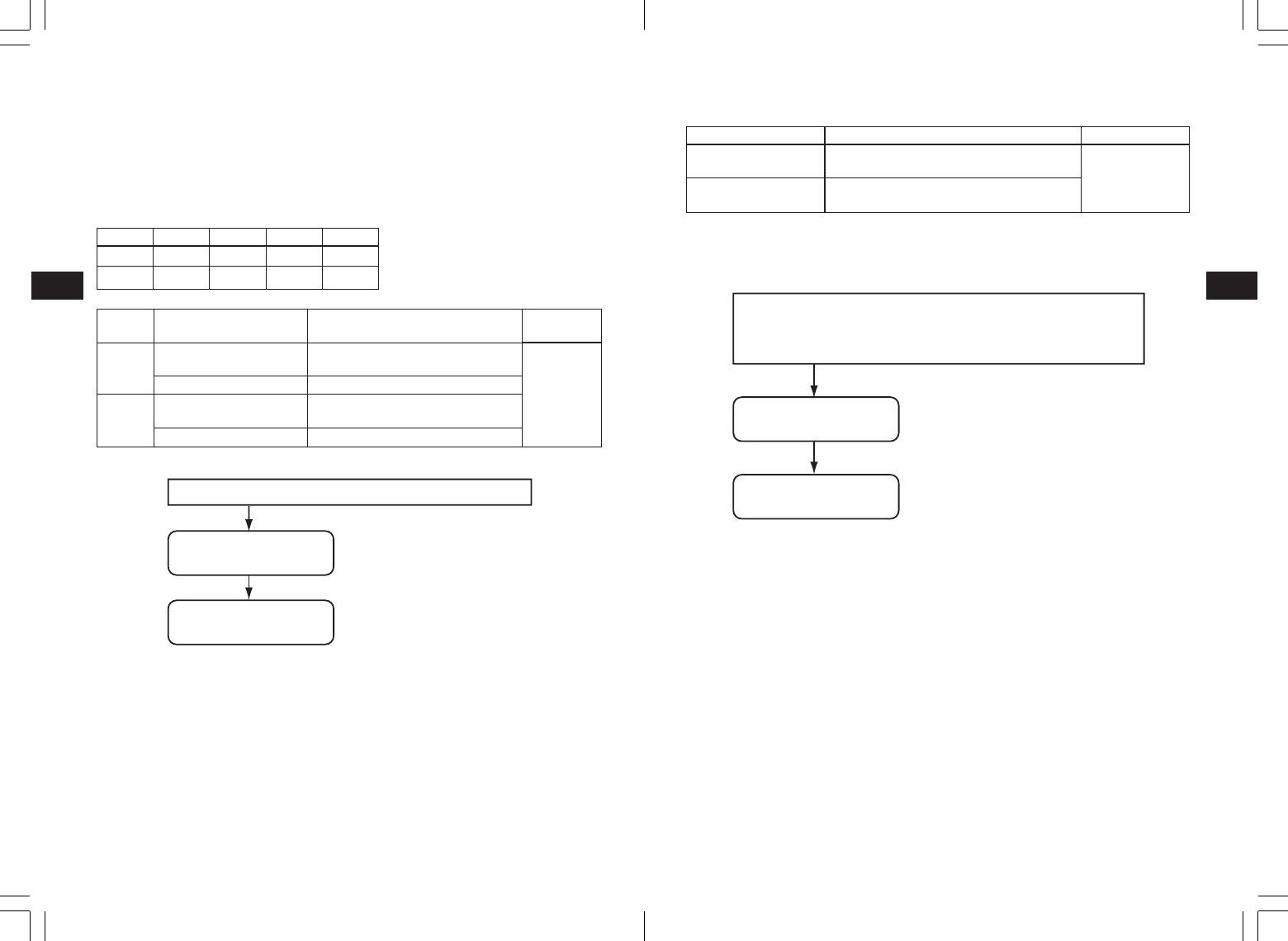
Standard/non-standard code setting mode
Standard code/non-standard code settings for control codes can be changed using the
control code setting command.
Change standard/non-standard code setting
The standard code/non-standard code setting is changed by the DIP switch (DSW) settings
when the power is turned on, and by button settings. The settings are enabled upon turning
the power off.
Note: When the buzzer sound mode is enabled, the buzzer sounds upon startup. Release
the PRINT/FEED button to stop the buzzer.
To check the settings for the standard code/non-standard code setting mode, see
the test print output (See P. 23).
To end standard code/non-standard code setting, confirm that the STATUS LED is
on in green, then turn power off. After changing the standard code/non-standard
code setting mode, be sure to restore the DSW to their original settings.
1 Non-standard code setting
DSW-1,2,3,4=(ON,ON,OFF,ON) + cover open + PRINT button + POWER
2 Standard code setting
DSW-1,2,3,4=(ON,ON,OFF,ON) + cover open + FEED button + POWER
Processing setting
(STATUS LED flashes green)
Setting completes
(STATUS LED lights green)
Type
Standard code setting
Non-standard code
setting
Default
Standard code
setting
Standard/non-standard specifications
Control code Binary
STX 02H
ETX 03H
ESC 1BH
ENQ 05H
CAN 18H
NULL 00H
Control code Binary
STX 7BH({)
ETX 7DH())
ESC 5EH(^)
ENQ 40H(@)
CAN 21H(!)
NULL 7EH(~)
1 Disable buzzer sound
DSW-1,2,3,4=(OFF,OFF,ON,ON) + cover open + PRINT button + POWER
2 Enable buzzer sound
DSW-1,2,3,4=(OFF,OFF,ON,ON) + cover open + FEED button + POWER
Processing setting
(STATUS LED flashes green)
Setting completes
(STATUS LED lights green)
Note: When the buzzer sound mode is enabled, the buzzer sounds upon startup.
Release the PRINT/FEED button to stop the buzzer. To check the settings for the
buzzer sound setting mode, see the test print output (See P. 23).
To end buzzer sound setting, confirm that the STATUS LED is on in green, then turn
the power off. After changing the buzzer sound setting mode, be sure to restore the
DSW to their original settings.
Change buzzer sound setting
Buzzer sound mode setting
A buzzer can be sounded upon starting up the printer and upon errors. The buzzer is
enabled by default. This can be enabled or disabled by the initial operation and by online
command.
Reference
14
55
Reference
14
54
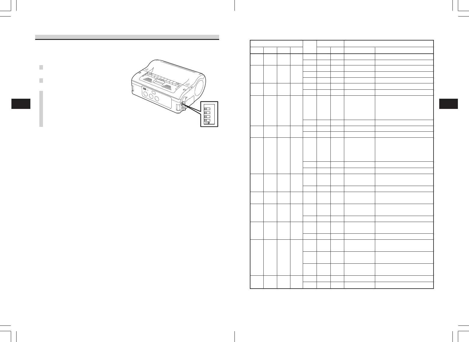
•DIP switch setting items
DIP switch Startup modeButton
1
OFF
OFF
OFF
OFF
OFF
OFF
ON
ON
ON
ON
ON
ON
2
OFF
OFF
OFF
ON
ON
ON
OFF
OFF
OFF
ON
ON
ON
3
OFF
ON
OFF
OFF
OFF
ON
OFF
ON
OFF
OFF
ON
OFF
4
OFF
ON
ON
OFF
ON
ON
OFF
ON
ON
OFF
ON
ON
Cover
CLOSE
CLOSE
CLOSE
OPEN
OPEN
OPEN
OPEN
CLOSE
CLOSE
OPEN
OPEN
CLOSE
OPEN
OPEN
CLOSE
CLOSE
CLOSE
OPEN
OPEN
CLOSE
CLOSE
CLOSE
OPEN
OPEN
OPEN
OPEN
PRINT
OFF
OFF
OFF
ON
OFF
ON
OFF
OFF
OFF
ON
OFF
OFF
ON
OFF
OFF
OFF
OFF
ON
ON
OFF
OFF
OFF
ON
OFF
ON
OFF
Interface
RS-232C
–
RS-232C
–
–
–
–
Bluetooth
interface
Wireless LAN
interface
–
–
–
Bluetooth
interface
Wireless LAN
interface
–
–
Infrared
interface
–
Infrared
interface
–
–
USB
interface
–
USB
interface
–
–
–
–
Content
Normal printing mode
User test printing mode
HEX dump mode
Buzzer sound disabled
Buzzer sound enabled
Automatic dispenser printing setting
Manual dispenser printing setting
Normal printing mode
User test printing mode
Head check (printing area) setting
Head check disabled
HEX dump mode
CRC check enabled
CRC check disabled
Normal startup mode
Test printing mode
HEX dump mode
Head check
(Barcode printing area) setting
Head check disabled
Normal operation
Test printing mode
HEX dump mode
Online command setting
(compatible with MB400)
Online command setting
(SBPL command)
Non-standard code setting
Standard code setting
FEED
OFF
ON
OFF
OFF
ON
OFF
ON
OFF
ON
OFF
ON
OFF
OFF
ON
OFF
ON
OFF
OFF
OFF
OFF
ON
OFF
OFF
ON
OFF
ON
DIP Switch
•Setting DIP switch
2341
ON
1Turn the power OFF.
2Open the DIP switch cover.
3Use a pointed object, such as the
tip of a ballpoint pen, to change
the switch position.
Reference
14
57
Reference
14
56
Item
Character magnification
Character rotation
Fonts
Barcode
2-D code
Switch
Display
Buzzer
Safety or Noise standard
Protective circuit
Water resistance
Environment conditions
(including battery pack)
Options
MB400i MB410i
1 to 6 times
0°, 90°, 180°, 270°
SATO standard fonts: ×20, ×21, ×22, ×23, ×24, OCR-A, OCR-B, POP fonts
Kanji 16 × 16, 22 × 22, 24 × 24 square Gothic (JIS level-1 and level-2 set),
Mark-down fonts
JAN/EAN8, JAN/EAN13, UPC-E/UPC-A, NW-7, CODE39, CODE93, CODE128,
INTERLEAVED 2 of 5, customer barcode, RSS-14
*However, barcodes are to be used at:
Parallel barcode: thin bar width 2 dots or more
Serial barcode: thin bar width 3 dots or more
PDF417, QR code (includes micro QR), Data matrix code (ECC200),
MAXI code, composite symbols
POWER button, PRINT button, FEED button
STATUS LED: 1 (lights in three colors: green, red, and orange)
Battery remaining power display LED :
3 (lights in two colors: green and red)
Printer status information buzzer
FCC15B, FCC15C, EN55022, EN55024, EN61000-3-2, EN61000-3-3,
GB4943, GB9254, GB17625.1
Overcharging prevention, over-discharging prevention, head overheating
protection function, low battery detection
Meets IPX3 JIS C0920-2003
When using waterproof case (option)
*Excludes when communication cable is connected.
Operating ambient temperature :
-15 to 50°C (for wireless LAN: 0 to 50°C)
Humidity : 20 to 80% Non-condensing
Storage ambient temperature : -25 to 60°C
Humidity : 20 to 80% Non-condensing
Excludes paper environment
Battery pack, AC adapter, battery charger (single), waterproof case, belt
case, RS-232C cable, USB cable
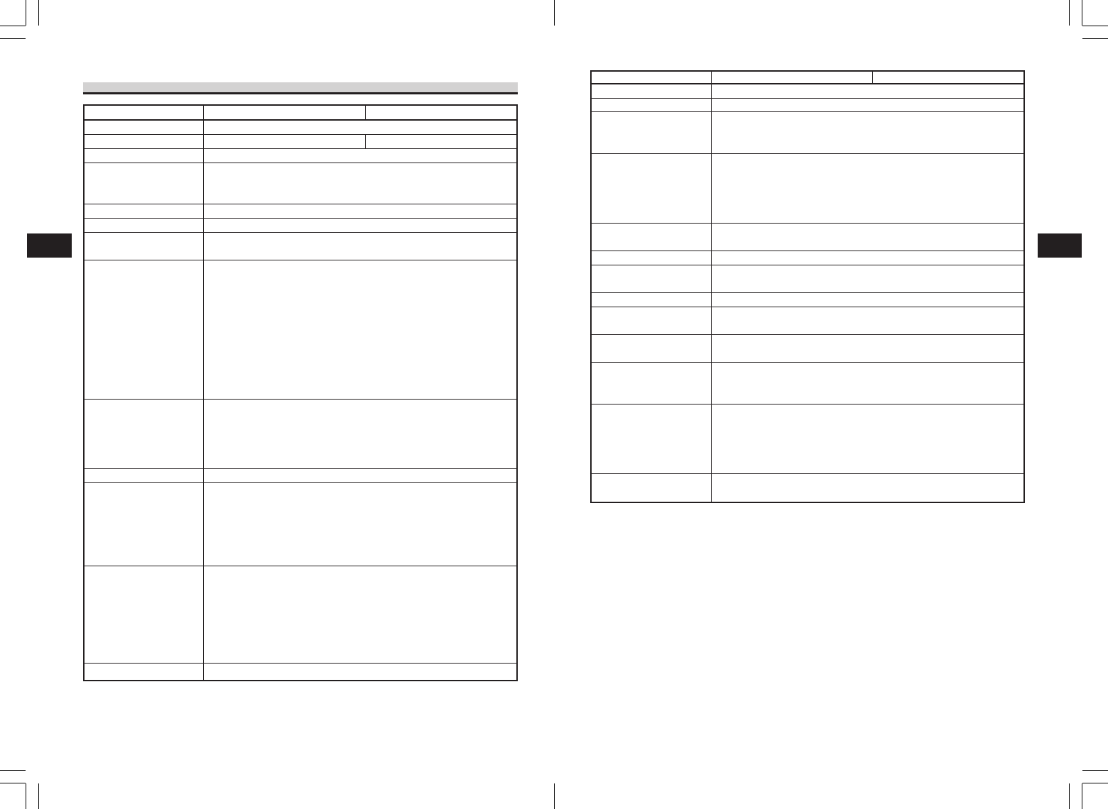
Basic Specifications of MB400i/MB410i
Item
Printing method
Head density
Maximum effective printing area
Printing speed
Dimensions
Weight
Power source (battery)
Paper
Paper thickness
Paper shape
Label size (backing liner
and eye-mark pitch)
Label printing
Self-diagnosis function
Low power consumption
function
Interface
•RS-232C
•USB
• Optical coupling
•Bluetooth option
•Wireless LAN option
Paper sensor
MB400i MB410i
Thermal printing
8 dots/mm (203 dpi) 12 dots/mm (305 dpi)
104 mm (width) × 297 mm (pitch)
Maximum 103 mm/sec. (printing speed is 75 mm/sec. during dispenser
printing). Differs depending on printing rate and usage environment.
Printing speed can be changed using the printing speed setting command.
170 mm (width) × 76 mm (depth) × 134 mm (height) (excluding protruded parts)
750 g or less (Standard specifications; including the battery pack)
Pack type (lithium ion) 1700 mAh can continuously print four rolls of thermal labels
(equivalent to 50 m) when fully charged (however, at a printing rate of 16% or less).
Always use genuine SATO labels.
0.064 mm to 0.190 mm
Roll media: Face-out winding
Maximum outer diameter: φ 58 mm
Standard Width 50 to 111 mm (53 to 114 mm)
Pitch: 25 to 297 mm (28 to 300 mm)
Dispenser Width 50 to 111 mm (53 to 114 mm)
Pitch: 25 to 182 mm (28 to 185 mm)
Non-separated Width 53 to 107 mm
Pitch: 28 to 182 mm
Continuous printing (Paper sensor enabled)
Dispenser printing (Paper sensor enabled)
Journal printing (Paper sensor disabled)
Non-separated printing (Paper sensor enabled)
Label printing can be changed using the printer command <PG>.
Head check/battery check/paper out/cover open/test printing
Enters sleep mode after five seconds of non-activity (button press, data
reception or cover operation). Automatically powers off after five minutes of
continued non-activity. Note: The default setting for the Bluetooth or the
wireless LAN models is to disable automatic power-off.
The automatic power-off time can be changed using the <PG> printer
operation command. For command details, see the programming guide.
Mini DIN (specified)
mini B type
Infrared communication (compliant with IrDA Standard Ver 1.2)
Bluetooth Specification Ver1.1 Class2
Wireless LAN interface (IEEE 802.11b/g)
TCP/IP (FTP, LPR, SOCKET)
Reflective sensor (I-mark), transmission type (gap)