Sato RWMTM1 RFID Reader User Manual M4e Product Spec Sheet 1 3a ext
Sato Corporation RFID Reader M4e Product Spec Sheet 1 3a ext
Sato >
Revised Users Manual
3/17/2006 ThingMagic 1/7
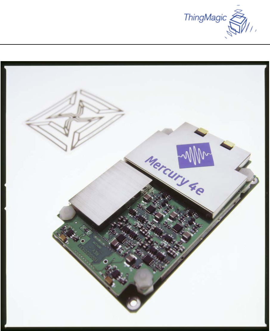
Mercury4e™
Specification Sheet
Mercury4e Specification Sheet v1.3
3/17/2006 ThingMagic 2/7
Table of Contents
1. Introduction....................................................................................................................... 3
2. Mercury4e™ Reader Specification Overview................................................................. 3
3. Physical Connection and Pin-Out..................................................................................... 5
4. Protocol Support ............................................................................................................... 5
5. Mechanical Drawing......................................................................................................... 6
6. Regulatory Installation Requirements............................................................................... 7
7. End Product Labeling ....................................................................................................... 7

Mercury4e Specification Sheet v1.3
3/17/2006 ThingMagic 3/7
1. Introduction
The Mercury4e™ is ThingMagic’s entry in the embedded reader market, which comprises
label printers, label applicators, and handheld terminals. Unlike previous members of
ThingMagic’s Mercury family, the Mercury4e™ readers are designed for embedded
applications within a host system. They interface with a host system via asynchronous serial
(TTL-level RS-232) using a packetized polled mode communication. Anti-collision
capability is not provided in the initial release of the Mercury4e product.
Mercury4e™ readers have a single on-board processor, a TI 55xx series DSP. The reader
operates in a single-tasking, streaming mode where tag IDs are sent back to the host
processor one-at-a-time, in a mode suitable for small tag populations where reading occurs
primarily when triggered by the host system. This is envisioned to occur in response to the
host system’s request when a label is aligned beneath the print head in a printer application.
2. Mercury4e™ Reader Specification Overview
Requirement Value
Dimensions 5.5cm x 9cm x 1.5cm
RFID Tag and
Protocol
Support
Host-switched multi-protocol:
EPC Global Class 0 (including Symbol and Impinj Class 0+ R/W)
EPC Class 1 R/W (64 and 96 bit silicon)
EPC Generation 2 R/W*
ISO18000-6B R/W
Frequency 902-928 MHz, for FHSS use and certification in the US and
Canada
RFID Tag Read
and Write Rates Read/write rate and range is protocol dependent and will vary
depending on RF signal strength and other environmental factors.
Antenna
Connectors 2 MMCX connectors for two antennas. Unit will tolerate 2:1
VSWR without damage, but a VSWR below 1.5:1 will be needed
for best performance. Circular polarization is supported.
Module Power
Supply Fixed 5.3 VDC +/- 4% DC supply voltage, average power
dependent on duty cycle. Peak power not more than 8.8W. Power
supply ripple and noise must be less than 100mV pp, and the host
power supply load transient response must support a dI/dT of
500kA/s with less than 100mV over/undershoot.
RF Power
Output RF power output depends on available peak supply current. RF
output power is variable in 0.1dB steps from 20dBm to 24dBm.
Absolute accuracy of RF output power is +/- 1dB.

Mercury4e Specification Sheet v1.3
3/17/2006 ThingMagic 4/7
Requirement Value
Sleep Mode The module can be put in and out of sleep mode by the host
processor.
Host
Communication 3.3/5V logic level, async serial according to ThingMagic’s
MercuryE Communication Protocol Document. The serial
interface includes the settings 115.2 and 38.4 kbaud, 8,n,1, no flow
control.
Firmware Firmware is upgradeable via serial port. Unit first boots into a
write-protected bootloader region, verifies CRC of the full
firmware image, waits for a Go (or Firmware Upload) command
from the host system, and then runs that firmware image. If a valid
image is not found by the bootloader, the bootloader waits for a
Firmware Upload per the Communication Protocol Document.
Temperature
Operating and
Storage
Operating ambient temp range 0C-60C.
Storage temp range better than –40C to +85C.
ESD 10kV to antenna shield conductor. Recommend the use of an
antenna that presents a DC short to endure 10kV- this is TBD
pending testing.
Regulatory FCC Class B (digital portion) and 15.247 (FHSS radio): Test
commands for type acceptance testing will be provided.
Certification Certification by OEM customer

Mercury4e Specification Sheet v1.3
3/17/2006 ThingMagic 5/7
3. Physical Connection and Pin-Out
The host connector is an AMP part number 4-440372-2 right angle male 1.27mm header. It
mates with an AMP part number 1-440146-0 socket and 440147-1 pins.
Pin Number Function
1 5.3 VDC +/- 4%
2 5.3 VDC +/- 4%
3 Ground
4 Ground
5 Output 1 (GPIO from module)
6 Output 2 (GPIO from module)
7 Input 1 (GPIO to module)
8 Input 2 (GPIO to module)
9 Asynchronous Serial RX (from host to module)
10 Asynchronous Serial TX (from module to host)
4. Protocol Support
ThingMagic will provide the following air interface protocols and functionality. Additional
protocols and their functionality will be provided on a quoted basis.
ID
Read ID
Write Data
Read Data
Write Password
Write Lock
EPC Global Class 0
(including Symbol and
Impinj Class 0+ R/W)
9 9 9 (0+) 9 (0+) 9 (0+)
EPC Class 1 (V1) 9 9 9 9
EPC UHF Gen2 9 9 9 9 9 9
ISO 18000-6b 9 9 9
Mercury4e Specification Sheet v1.3
3/17/2006 ThingMagic 6/7
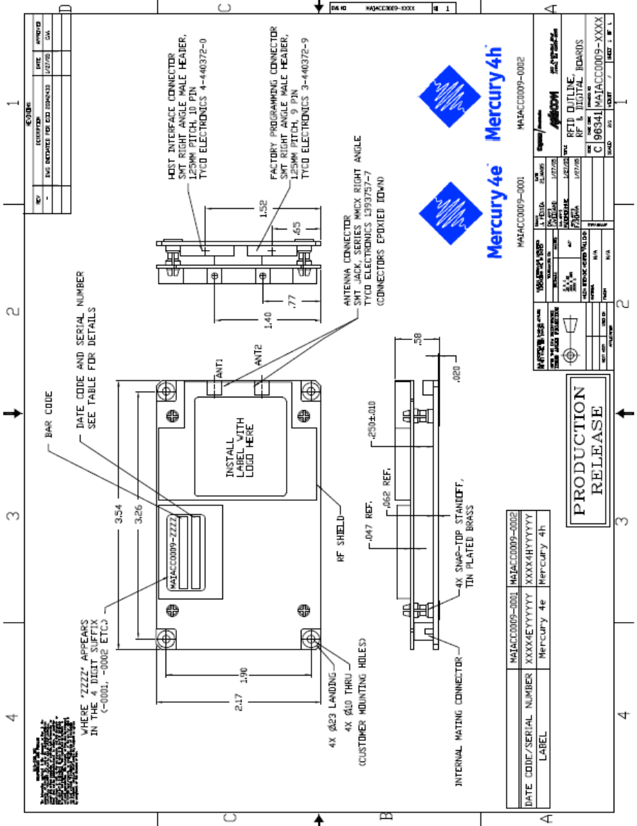
5. Mechanical Drawing
Mercury4e Specification Sheet v1.3
3/17/2006 ThingMagic 7/7
6. Regulatory Installation Requirements
This device is intended for OEM integrators only. It is the OEM integrator’s responsibility to
obtain FCC modular authorization for this device. Once authorized it must be used only
under the following conditions:
1) The antenna must be installed such that 20 cm is maintained between the antenna and
users, and
2) The transmitter module may not be co-located with any other transmitter or antenna.
As long as the two conditions above are met, further transmitter testing will not be required.
The OEM integrator is responsible for testing their end-product for any additional
compliance requirements required with this module installed (for example, digital device
emissions, PC peripheral requirements, etc.).
IMPORTANT NOTE: In the event that these conditions can not be met (for example certain
laptop configurations or co-location with another transmitter), then the FCC authorization is
no longer considered valid and the FCC ID can not be used on the final product. In these
circumstances, the OEM integrator will be responsible for re-evaluating the end product
(including the transmitter) and obtaining a separate FCC authorization.
The end user should not be provided any instructions on how to remove or install the device.
Changes or modifications not expressly approved by the party responsible for compliance
could void the user’s authority to operate the equipment.
7. End Product Labeling
This transmitter module is authorized only for use in devices where the antenna may be
installed such that 20 cm may be maintained between the antenna and users (for example
access points, routers, wireless ASDL modems, and similar equipment). The final end
product must be labeled in a visible area with the following:
“Contains TX FCC ID: <FCC ID #>”.