Sato M84Pro Users Manual M84p Service Manual2s
M84PRO to the manual 279f9e5b-51d3-436b-b198-a587e11122f1
2015-02-06
: Sato Sato-M84Pro-Users-Manual-526342 sato-m84pro-users-manual-526342 sato pdf
Open the PDF directly: View PDF ![]() .
.
Page Count: 135 [warning: Documents this large are best viewed by clicking the View PDF Link!]
PN 9001111A
M84PRO
Thermal Transfer Printer
SERVICE MANUAL
SATO America, Inc.
10350A Nations Ford Road
Charlotte, NC 28273
Main Phone: (704)644-1650
Tech Support Hotline: (704)644-1660
Tech Support Fax: (707)644-1661
E-Mail: satosales@satoamerica.com
www.satoamerica.com
© Copyright 2003
SATO America, Inc.
All rights reserved. No part of this document may be reproduced or issued to third parties in any
form whatsoever without the express permission of SATO America, Inc. The materials in this
document is provided for general information and is subject to change without notice. SATO
America, Inc. assumes no responsibilities for any errors that may appear.
Preliminary 02/01/03
PN 9001111A
TABLE OF CONTENTS
INTRODUCTION
General Description 1-2
Theory Of Operation 1-2
Switches And Indicators 1-4
Connection Ports 1-4
TECHNICAL DATA
Physical Characteristics 2-1
Power 2-1
Enviromental 2-1
Print 2-1
Media 2-2
Ribbon 2-2
Sensing 2-2
Interface Modules 2-2
Processing 2-3
Character Font Capabilities 2-3
Bar Code Capabilities 2-4
Regulatory Approvals 2-4
INTERFACE SPECIFICATIONS
Interface Types 3-1
Receive Buffer 3-1
IEEE1284 Parallel Interface 3-3
RS232 Serial Interface 3-4
Universal Serial Bus (Usb) Adapter 3-6
Local Area Network (Lan) Interface 3-6
Bi-Directional Communications 3-6
ACCESSORIES INSTALLATION
Label Cutter 4-1
Dispenser 4-4
Flash Memory 4-7
PCMCIA Memory Expansion 4-8
Real-time Clock 4-10
Interface Module Upgrade 4-12
CONFIGURATION
Dip Switch Panels 5-1
RS232 Transmit/receive Setting 5-1
Printer Setup 5-3
Default Settings 5-7
Software Default Settings 5-7
Potentiometer Adjustments 5-8
LCD Panel Printer Configuration 5-9
TROUBLESHOOTING
Error Signals 6-1
Troubleshooting Table 6-2
Troubleshooting Procedures 6-4
PN: 9001111A
REPLACEMENT PROCEDURES
Main Circuit Board 7-1
Interface Board (Module) 7-3
Daughter Board 7-4
Memory Board (Card) 7-5
Power Board 7-5
Panel Board 7-6
LCD Board 7-7
Fuse 7-8
Motor 7-9
Platen Roller 7-11
Feed Roller 7-12
Timing Belt 7-14
Print Head 7-18
Label-out Sensor Switch 7-20
Label Position Sensor 7-22
Ribbon Sensor 7-23
Cutter Belt 7-25
Cutter Circuit Board 7-27
ADJUSTMENT PROCEDURES
Print Head Position Alignment 8-2
Print Head Balance 8-3
Ribbon Guide Plate 8-5
Feed Roller 8-6
Timing Belt 8-8
Pitch Sensor Setup For Notched Tags 8-9
Print Position 8-10
Label Gap Sensor 8-11
Eye-Mark Sensor 8-13
Offset Label Stop Position 8-14
LCD Display 8-14
Print Darkness 8-15
FACTORY RESETS
Factory Settings/Test Print 9-1
Clear Head Counters 9-2
Clear Dispenser Counter 9-3
Clear Cutter Counter 9-4
Clear EEPROM 9-5
DIAGRAMS & SCHEMATICS
Housing Cover Removal & Installation 10-1
Media Loading 10-2
Ribbon Loading 10-2
Paper Specifications 10-3
Accessories & Sensors Location 10-4
Print Position Reference 10-5
Print Operation Sequence 10-6
M84Pro Service Manual PN: 9001111A Page 1-1
1
INTRODUCTION
This manual is laid out consistent with the product discussed and provides all of the information
required for general printer configuration, troubleshooting, and maintenance. For specialized
programming, refer to the Programming Manual also provided with the product.
Step-by-step maintenance instructions are provided with typical problems and solutions. It is
recommended that you become familiar with each section before installing and maintaining the
printer.
This manual also incorporates the use of special information boxes. Examples of these boxes
and the type of information provided in each, are below.
A comprehensive Table Of Contents provided at the front of this manual facilitates rapid
movement within. The contents identify the different unit sections and their respective sub-
sections. Each references the page number of their commencement.
The pages of this manual have embedded headers and footer to assist the user in identifying his
or her exact position within the manual. The header provides the section number followed by its
name. The footer identifies the product on the left, the manual’s part number in the center, and
the page number to the right side of the page.
Page enumeration is two-part with each separated by a hyphen. The first character set
references the section number and the second identifies the page number. Page numbers begin
with the numeral (1) one at the commencement of a new section and ascends sequentially.
WARNING: PROVIDES INFORMATION THAT, IF UNHEEDED MAY
RESULT IN PRESONAL INJURY.
CAUTION: PROVIDES INFORMATION THAT, IF UNHEEDED MAY RESULT
IN EQUIPMENT DAMAGE.
NOTE: Provides helpful hints to assist in performing the tasks at hand.
LCD DISPLAY: Provides the specific display that should be visible on the
LCD at that point.
Section 1: Introduction
M84Pro Service Manual PN: 9001111A Page 1-2
GENERAL DESCRIPTION
The M84Pro printer was designed for continuous industrial and commercial applications as self-
evident with its uncompromising all-metal housing, 203 to 609 dpi resolution, and label width
capacity up to 5 inches wide.
This printer uses standard SATO programming language with specific values for print
resolutions. These values are specified in “dots” and will vary depending upon the printer
resolution and the amount of memory available for label imaging.
The M84Pro was designed to be compatible with preceding M-8400 series printers. The main
difference is how it receives the command sequence and how it responds to certain commands.
Refer to the Operator and Technical Reference Manuals for additional information.
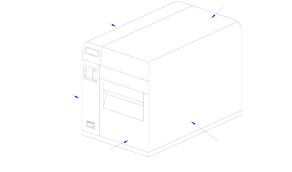
Figure 1-1, Primary Components
THEORY OF OPERATION
When activated, the media and ribbon (where applicable) are fed in conjunction past the print
head by an integrated drive train. The drive train is electric, stepper motor driven, coupled to a
gear configuration located on the left side of the printer chassis. Paper guides within the chassis
assembly ensure that the media remains properly positioned during the printing process and is
fed unimpeded through the front cover. The exhausted ribbon material is rewound onto a take-up
core inserted onto drive-train driven spindles.
A series of strategically located sensors send signals to the processing unit. The processing unit
in turn sends response signals to the various features based on programmed and received data.
Correct signals initiate print head activity.
LEFT HOUSING COVER
FRONT HOUSING COVER
PANEL COVER
RIGHT HOUSING COVER
TOP HOUSING COVER
Section 1: Introduction
M84Pro Service Manual PN: 9001111A Page 1-3
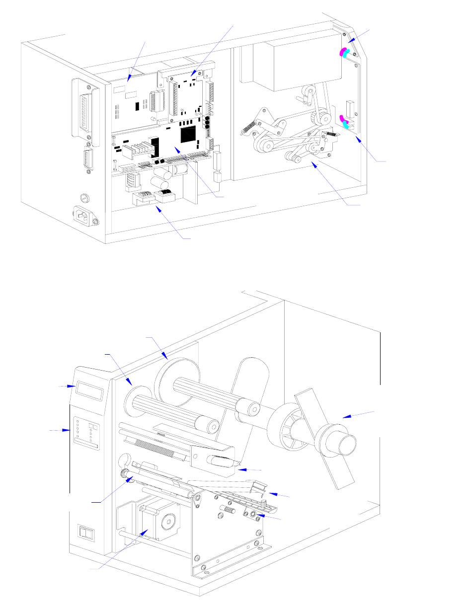
Figure 1-2, Primary Components
Figure 1-3, Primary Components
LCD BOARD
IEEE1284 + RS BOARD
PANEL BOARD
BELT CONFIGURATION
DAUGHTER BOARD
INTERFACE BOARD
MAIN CIRCUIT BOARD
POWER BOARD
PRINT ASSEMBLY
STEPPER MOTOR
LABEL HOLD DOWN
LABEL ROLL HOLDER
RIBBON REWIND SPINDLE
RIBBON SUPPLY SPINDLE
PLATEN ROLLER
LOWER FEED ROLLER
LCD PANEL
OPERATOR
PANEL
Section 1: Introduction
M84Pro Service Manual PN: 9001111A Page 1-4
SWITCHES AND INDICATORS
The table below identifies and defines printer switches and indicators for operator interface. The
accompanying graphics display their locations and appearance.
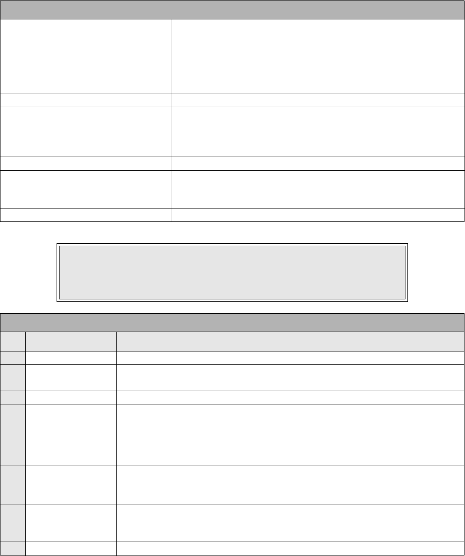
CONNECTION PORTS
These ports are externally accessible and permit connection of the accessories and attachments
necessary for printer programming and operation. Not listed here, are the connection ports of
circuit boards not externally accessible.
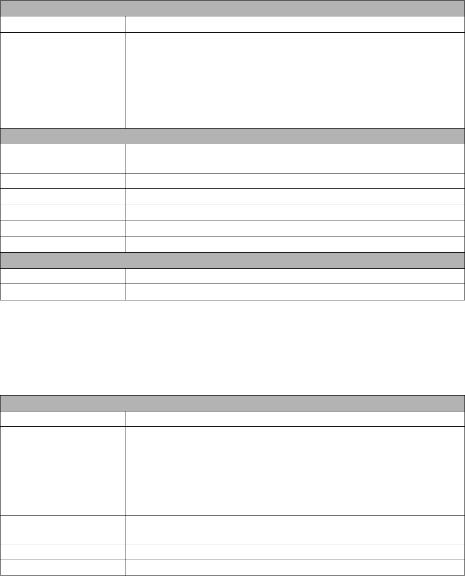
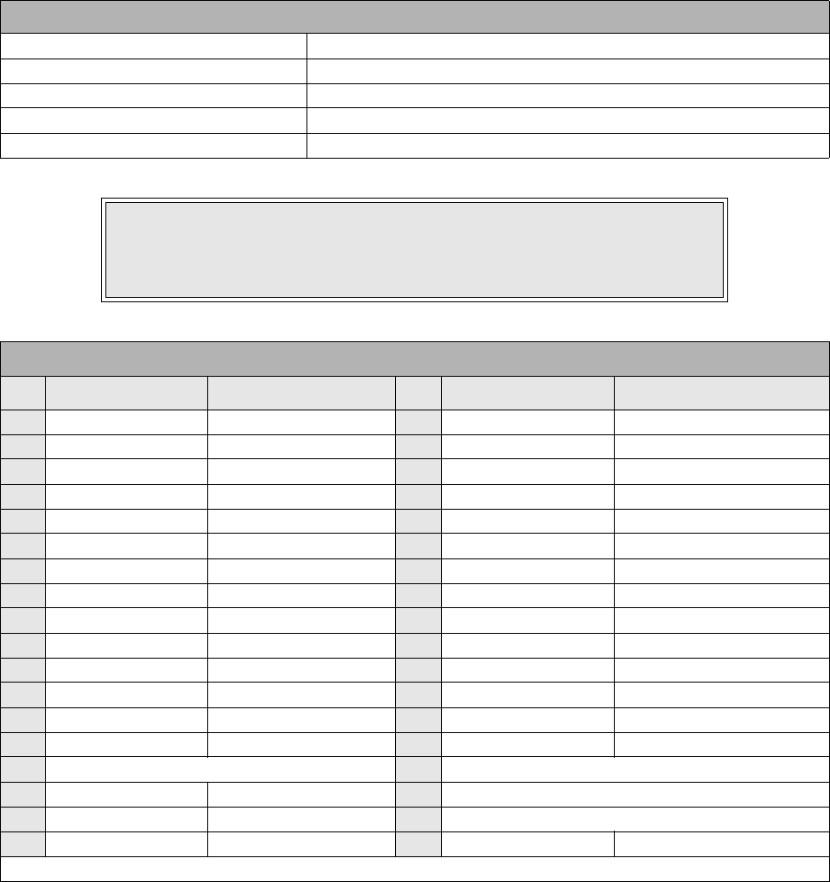
SWITCHES
Power Switch Two position on/off switch that controls power flow to the system.
Line Key Toggles the printer between the on-line and off-line modes. When
on-line, the printer is ready to receive data from the host. Acts as a
pause during print by taking the printer off-line. Also used as a scroll-
and-enter interface for printer setup.
Feed Key Feeds one blank label through the printer when off-line. When the
printer is on-line, another copy of the last label will be printed. Also
used as a scroll-and-enter interface for printer setup.
INDICATORS
LCD Display Dual line x 16 character display. Used for setting operational param-
eters and displaying error conditions.
Power Indicator Illuminates when the power switch is activated.
Label Illuminates when the label supply is depleted.
Ribbon Illuminates when the ribbon supply is depleted.
Error Illuminates when there is a system fault.
On-Line Illuminates when the system is operating.
DIP SWITCHES
DSW2 & DSW3 Sets operational parameters of printer.
DSW1 Used to configure optional RS232 communication card.
CONNECTION PORTS
AC Power Input Connector permits 115V, 50/60 Hz supply via supplied cord.
Interface Port Connector for interface harness. Must be connected for the printer to
be operational. Acceptable interface types are:
• RS232C Serial I/F Module, DB-25
• IEEE1284 Parallel I/F Module, AMP 57-40360
• Universal Serial Bus Adapter
• Ethernet 10/100 BaseT I/F Module
• RS422/485 I/F Module, DB-9
Ext. Interface Port Connector for external control of print cycle. Also supplies power for
optional accessories - AMP 57-60140
Memory Card Slot Slot for the insertion of optional PCMCIA Memory Card
Main Fuse Connection For input power protection - type 3A/250V
Section 1: Introduction
M84Pro Service Manual PN: 9001111A Page 1-5
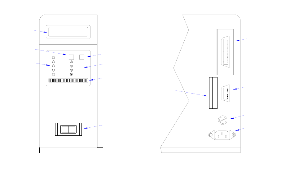
Figure 1-4, Switches, Indicators, and Connection Ports
LCD DISPLAY
POWER
LABEL
RIBBON
ERROR
ON LINE DISPLAY
PITCH
OFFSET
PRINT
LINE FEED
DSW1 DSW2 DSW3
INDICATORS
LINE KEY
POWER SWITCH
DIP SWITCHES
POTENTIOMETERS
FEED KEY
PANEL COVER REAR COVER
100V - 120V
FUSE T3.15A H 250V
EXT.
I/F
AC POWER INPUT
MAIN FUSE CONNECTI
O
EXT PORT
INTERFACE PORT
MEMORY CARD SLOT
M84Pro Service Manual PN: 9001111A Page 2-1
2
TECHNICAL DATA
All technical data deemed pertinent has been tabulated below for quick reference. Find the
relative section header and then locate the specific type of technical data in th left column.
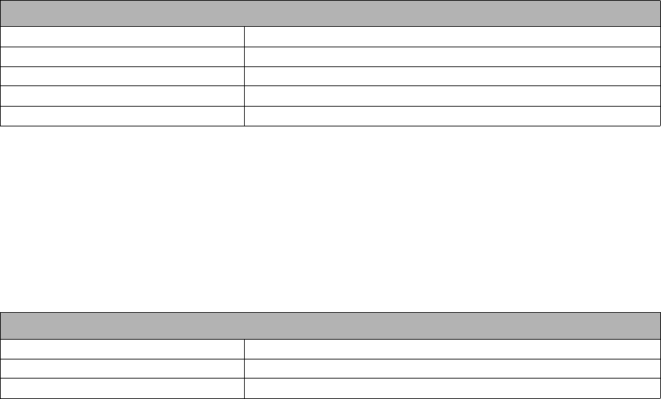
PHYSICAL CHARACTERISTICS
Width 10.4 Inches (265 mm)
Height 13.4 Inches (341 mm)
Depth 17.1 Inches (435 mm)
Weight 39.7 Pounds (18.0 mm)
POWER
Input Voltage 115/220 Volts AC +/- 10%, 50/60 Hertz +/-1%
Power Consumption 130 Watt Operating, 24 Watt Idle
ENVIRONMENTAL
Operating Temperature 41° to 104°F (5° to 40°C)
Storage Temperature 23° to 140°F (-5° to 60°C)
Storage Humidity 30 to 90% RH Non-Condensing
Operating Humidity 30 to 80% RH Non-Condensing
Electrostatic Discharge 8kV
PRINT
Method Direct or Thermal Transfer
Speed (user selectable) M84PRO-2: 2 to 10 Inches Per Second (50 - 250 mm/s)
M84PRO-3: 2 to 8 Inches Per Second (50 - 200 mm/s)
M84PRO-6: 2 to 6 inches Per Second (50 - 150 mm/s)
Print Module (dot size) M84PRO-2: .0049 Inches (.125 mm)
M84PRO-3: .0033 Inches (.083 mm)
M84PRO-6: .0017 Inches (.081 mm)
Resolution M84PRO-2: 203 Dots Per Inch (8 d/mm)
M84PRO-3: 305 Dots Per Inch (12 d/mm
M84PRO-6: 609 Dots Per Inch (24 d/mm)
Maximum Print Width 4.1 Inches (104 mm)
Maximum Print Length M84PRO-2: 49.2 Inches (1249 mm)
M84PRO-3: 32.8 Inches (835 mm)
M84PRO-6: 14.0 Inches (356 mm)
Section 2: Technical Data
M84Pro Service Manual PN: 9001111A Page 2-2
MEDIA
Minimum Width .87 Inches (22 mm)
Minimum Length
Continuous
Tear-Off
Cutter
Dispense
0.24 Inches (6 mm)
0.63 Inches (16 mm)
1.18 Inches (30 mm)
1.18 Inches (30 mm)
Maximum Width 5.0 Inches (125 mm)
Type Die Cut Labels, Fan-Fold, Tag Stock or Continuous
Maximum Caliper .008 Inches (.21 mm)
Maximum Roll Diameter 8.6 Inches (220 mm), Wound face inward
Minimum Core Diameter 3 Inches (76.2 mm)
RIBBON
Maximum Width 4.4 Inches (111 mm)
Length 1475 Feet (450 m)
Thickness 4.5 Microns, Wound face inward
SENSING
See-Through for labels or tags Movable
Reflective Eye-Mark Movable
Continuous Form Sensor not used.
INTERFACE MODULES
Parallel Port IEEE 1284 Standard
Serial Port RS232C (9600 to 57,6000 dps) Standard
RS422/485 (9600 to 57600 bps) Optional
Ready/Busy or X-On/X-Off Flow Control
Bi-Directional Status
Universal Serial Bus USB Adapter
Ethernet 10/100 Base T, 802.116 Wireless Wi-Fi
Data Transmission ASCII Format
PROCESSING
CPU 32 Bit RISC
FLash ROM 2 Mega-Bytes
SDRAM 16 Mega-Bytes
Receive Buffer 2.95 Mega-Bytes
Memory Expansion See Options and Accessories
Section 2: Technical Data
M84Pro Service Manual PN 9001111A Page 2-3
CHARACTER FONT CAPABILITIES
MATRIX FONTS
U Font 5 dots W x 9 dots H
S Font 8 dots W x 15 dots H
M Font 13 dots W x 20 dots H
XU Font 5 dots W x 9 dots H (Helvetica)
XS Font 17 dots W x 17 dots H (Univers Condensed Bold)
XM Font 24 dots W x 24 dots H (Univers Condensed Bold)
OA Font (OCR-A) M84PRO-2: 15 dots W x 22 dots H
M84PRO-3: 22 dots W x 33 dots H
M84PRO-6: 44 dots W x 66 dots H
OB Font (OCR-B) M84PRO-2: 30 dots W x 36 dots H
M84PRO-3: 30 dots W x 36 dots H
M84PRO-6: 60 dots W x 72 dots H
AUTO SMOOTHING FONTS
WB 18 dots W x 30 dots H
WL 28 dots W x 52 dots H
XB 48 dots W x 48 dots H (Univers Condensed Bold)
XL 48 dots W x 48 dots H (Sans Serif)
VECTOR FONT
Proportional or Fixed Spacing
Font Size 50 x 50 dots to 999 x 999 dots
Helvetica, 10 Font Variations
AGFA RASTER FONTS
A Font CG Times, 8 to 72 pt.
B Font CG Triumvirate, 8 to 72 pt.
DOWNLAODABLE FONTS
Bit Mapped True Type Fonts with Utility Program
CHARACTER CONTROL
Expansion up to 12 x in either the X or Y coordinates.
Charcter Pitch Control
Line Space Control
Journal Print facility
0, 90, 180, and 270 Degree Rotation
Section 2: Technical Data
M84Pro Service Manual PN: 9001111A Page 2-4
BAR CODE CAPABILTIES
Linear Bar Codes Bookland (UPC/EAN Supplemental
EAN-8, EAN-13
CODABAR
Code 39
Code 93
Code 128
Interleaved 2 of 5
Industrial 2 of 5
Matrix 2 of 5
MSI
POSTNET
UCC/EAN-128
UPC-A and UPC-E
Two Dimemsional Data Matriix
Maxicode
PDF417
Micro PDF
Truncated PDF
QR Code
RSS-14 Composite Code
Ratios 1:2, 1:3, 2:5, User definable bar widths
Bar Height 4 to 999 dots, User progammable
Rotation 0, 90, 180, and 270 Degrees
Sequential Numbering Sequential numbering of both numerics and bar codes
Custom Characters RAM storage for special characters
Graphics Full dot addressable graphics, SATO Hex/Binary, .BMP or
.PCX formats
Form Overlay Form overlay for high-speed editing of complex formats
REGULATORY APPROVALS
Safety VCCI (Class B), UL, CUL, CE, FCC (Class B)
RFI/EMI FCC (Class B)
M84Pro Service Manual PN: 9001113A Page 3-1
3
INTERFACE SPECIFICATIONS
This section presents the interface specifications and include detailed information on how to
properly interface the printer with the host system.
INTERFACE TYPES
The parallel interface is a high speed, bi-directional interface that conforms to the IEEE1284
specification (ECP mode on some computers). The interface is also compatible with the older
Centronics parallel interface standard. If it does not detect the correct IEEE1284 signals in the
interface connection, it will automatically operate in the standard Centronics mode which is much
slower. To use the IEEE1284 parallel interface to its fullest capability requires that the host also
have an IEEE1284 compatible interface and that the two be connected with a cable that meets
the IEEE1284 specification. If either of these two are not present, the data rate is reduced.
In order to provide flexibility in communicating with a variety of host computer systems all printers
use a Plug-In Interface Module. The IEEE1284 Interface module is shipped with the printer
unless another interface type is specified at the time of the order. The other interfaces available
is a high speed serial interface, an Ethernet interface, wireless Ethernet, or an optional Universal
Serial Bus (USB) Adapter.
The Parallel interface will probably be the most useful in communicating with IBM PCs and
compatibles. The RS232C Serial interface allows connectivity to a number of other hosts. The
USB interface allows the printer to be connected to a computer that supports peripherals
attached to a USB bus. Up to 127 peripherals can be connected to a single USB port.
RECEIVE BUFFER
The printer may be configured to receive a data stream from a singular or multiple print jobs. The
single job print buffer is generally used by software programs that wish to maintain control of the
job print queue so that it can move a high priority job in front of ones of lesser importance. The
multiple job buffer, on the other hand prints all jobs in the order they are received by the printer,
and the order of printing cannot be changed.
SINGLE JOB BUFFER
The printer receives and prints one job at a time. Each job must not exceed 2.95 MB.
WARNING: NEVER CONNECT OR DISCONNECT INTERFACE CABLES
(OR USE A SWITCH BOX) WITH POWER APPLIED TO EITHER THE
HOST OR THE PRINTER. THIS MAY CAUSE DAMAGE TO THE
INTERFACE CIRCUITRY IN THE PRINTER/HOST AND IS NOT COVERED
BY WARRANTY.
Section 3: Interface Specifications
M84Pro Service Manual PN 9001113A Page 3-2
MULTIPLE JOB BUFFER
The printer is able to continuously receive print jobs while compiling and printing other jobs at the
same time. It acts much like a “print buffer” to maximize the performance of the host and the
printer. When using the RS232C Serial interface, the multiple job buffer uses either the Ready/
Busy with DTR (pin 20) or X-On/X-Off flow control protocols. See these sections for more details.
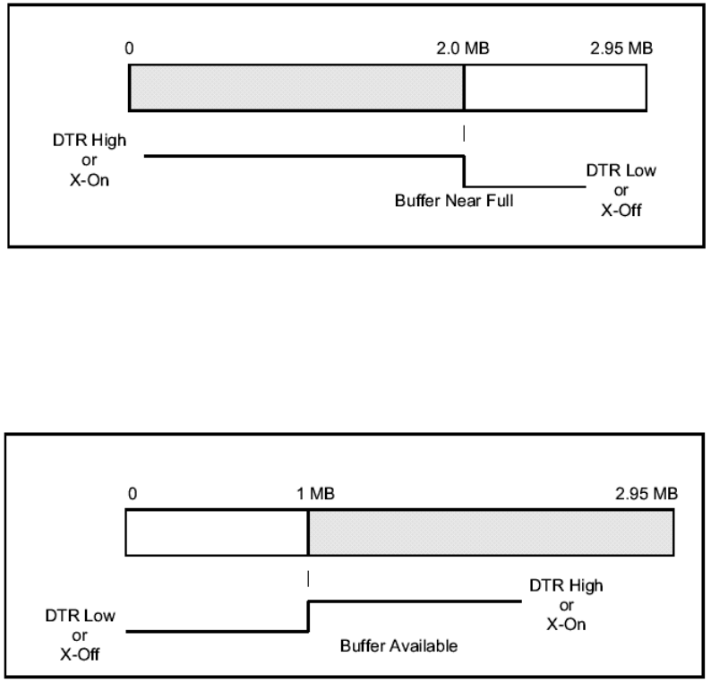
With an empty receiving buffer, the status of DTR is “high” (in X-On status if using X-On/X-Off)
meaning the printer is ready to receive data. When the receive buffer is holding 2.0 MB of data (1
MB from being full), DTR will go “low” (an X-Off is sent) indicating the printer can no longer
receive data. This condition is called “Buffer Near Full.”
The receiving buffer will not be able to receive more data again until a “Buffer Available” condition
occurs. This takes place when the receiving buffer has emptied so that only 1 MB bytes of data
are being held (2.0 MB bytes from being full). At this time, DTR will go “high” or an X-On is sent to
tell the host that it can again receive data.
All printer error conditions (i.e., label out, ribbon out) will cause the printer to go busy (DTR “low”
or X-Off) until the problem is corrected and the printer is placed on-line. The printer will also be
busy if taken off-line from the front panel.
Section 3: Interface Specifications
M84Pro Service Manual PN: 9001113A Page 3-3
IEEE1284 PARALLEL INTERFACE
The parallel interface for the M-84PRO printers is a Plug-In Interface Module that can be installed
by the user. It conforms to the IEEE1284 specification. It will automatically detect the IEEE1284
signals and operate in the high speed mode. If it does not detect the IEEE1284 signals, it will
operate in the standard Centronics mode, which is significantly slower. For this reason, an
interface cable and host interface conforming to the IEEE1284 specification must be present to
fully utilize the speed capabilities. This interface also operates bi-directionally and can report the
status of the printer back to the host.
SPECIFICATIONS
Printer Connector AMP 57-40360 DDK (or equivalent)
Cable Connector AMP 57-30360 DDK (or equivalent)
Cable IEEE1284 Parallel, 10 ft. (3 m) or less
Signal Level High = +2.4V to +5.0V, Low = 0V to -0.4V
Data Stream <ESC>A . . Job#1 . . <ESC>Z<ESC>A . . Job#n . . <ESC>Z
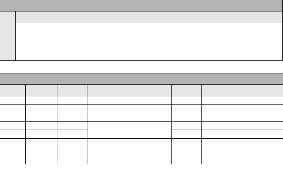
NOTE: Pin assignments begin with one (1) in the upper right corner and
descend to eighteen (18) in the upper left corner. Pin number nineteen (19)
picks up in the lower right corner and descends to thirty-six (36) in the lower
left.
IEEE 1284 PARALLEL INTERFACE PIN ASSIGNMENTS
PIN SIGNAL DIRECTION PIN SIGNAL DIRECTION
1 Strobe To Printer 19 Strobe Return Reference
2 Data 1 To Printer 20 Data 1 Return Reference
3 Data 2 To Printer 21 Data 2 Return Reference
4 Data 3 To Printer 22 Data 3 Return Reference
5 Data 4 To Printer 23 Data 4 Return Reference
6 Data 5 To Printer 24 Data 5 Return Reference
7 Data 6 To Printer 25 Data 6 Return Reference
8 Data 7 To Printer 26 Data 7 Return Reference
9 Data 8 To Printer 27 Data 8 Return Reference
10 ACK To Host 28 ACK Return Reference
11 Busy To Host 29 Busy Return Reference
12 Ptr Error To Host 30 PE Return Reference
13 Select To Host 31 INIT From Host
14 AutoFD1To Hos t 32 Fault To Host
15 Not Used 33 Not Used
16 Logic Gnd 34 Not Used
17 FG Frame Gnd 35 Not Used
18 +5V (z=24k ohm) To Host 36 SelectIn1From Host
1 Signals required for ieee 1284 mode.
Section 3: Interface Specifications
M84Pro Service Manual PN 9001113A Page 3-4
RS232 SERIAL INTERFACE
The High Speed Serial Interface is a Plug-In Interface Module that can be installed in the printer
by the user.
SPECIFICATIONS
Asynchronous ASCII Half-duplex communication
Ready/Busy Hardware Flow Control
Pin 20, DTR Control
Pin 4, RTS Error Condition
X-On/X-Off Software Flow Control
Bi-Directional Communication
Data Transmission Rate 9600, 19200, 38400, 57600 bps
Character Format 1 Start Bit (fixed)
7 or 8 data bits (selectable)
Odd, Even or No Parity (selectable)
1 or 2 Stop bits (selectable)
Connector DB-25S (Female)
Cable DB-25P (Male), 50 ft. maximum length.
For cable configuration, refer to Cable
Requirements appropriate to the RS232C protocol chosen.
Signal Levels High = +5V to +12V, Low = -5V to -12V
NOTE: Pin assignments begin with one (1) in the upper right corner and
descend to thirteen (13) in the upper left corner. Pin number fourteen (14)
picks up in the lower right corner and descends to twenty-five (25) in the
lower left.
RS232C SERIAL INTERFACE SIGNALS
PIN DIRECTION SIGNAL DEFINITION
1 Reference FG (Frame Ground)
2 To Host TD (Transmit Data) - Data from the printer to the host computer. Sends X-On/
X-Off characters or status data (bi-directional protocols).
3 To Printer RD (Receive Data) - Data to the printer from the host computer.
4 To Host RTS (Request to Send) - Used with Ready/Busy flow control to indicate an
error condition. RTS is high and remains high unless the print head is open (in
this case, RTS would return to the high state after the print head is closed and
the printer is placed back on-line) or an error condition occurs during printing
(e.g., ribbon out, label out).
5 To Printer CTS (Clear to Send) - When this line is high, the printer assumes that data is
ready to be transmitted. The printer will not receive data when this line is low. If
this line is not being used, it should be tied high (to pin 4).
6 To Printer DSR (Data Set Ready) - When this line is high, the printer will be ready to
receive data. This line must be high before data is transmitted. If this line is not
being used, it should be tied high (to pin 20).
7 Reference SG (Signal Ground)
Section 3: Interface Specifications
M84Pro Service Manual PN: 9001113A Page 3-5
READY/BUSY FLOW CONTROL
Ready/Busy is the hardware flow control method for the serial interface on the M-84PRO
printers. By raising/lowering the voltage level on Pin 20 of the RS232C port, the printer notifies
the host when it is ready to receive data. Pin 4 (RTS) and pin 20 (DTR) are the important signals
on the printer for this method of flow control. The host must be capable of supporting this flow
control method for it to function properly.
X-ON/X-OFF FLOW CONTROL
X-On/X-Off flow control is used whenever hardware (Ready/Busy) flow control is not available or
desirable. Instead of a voltage going high/low at pin 20, control characters representing ìPrinter
Readyî (X-On =11 hexadecimal) or “Printer Busy” (X-Off = 13 hexadecimal) are transmitted by
the printer on pin 2 (Transmit Data) to the host. In order for this method of flow control to function
correctly, the host must be capable of supporting it. X-On/X-Off operates in a manner similar to
the function of pin 20 (DTR) as previously explained. When the printer is first powered on it sends
an X-Off when the “Buffer Near Full” level is reached and a X-On when the data level of the buffer
drops below the “Buffer Available” mark. When the printer is taken off-line manually, it transmits
an X-Off indicating it cannot accept data. When it is placed back on line manually, it sends an X-
On, indicating it is again available for receipt of data. If an error occurs during printing (paper out,
ribbon out), the printer sends an X-Off as soon as an error condition is detected. When the error
is cleared and the printer is placed back on-line, it transmits an X-On indicating it is again ready
to accept data. Upon power up if no error conditions are present, the printer will continually send
X-On characters at five millisecond intervals until it receives a transmission from the host.
20 To Host DTR (Data Terminally Ready) - This signal applies to Ready/Busy flow control.
The printer is ready to receive data when this pin is high. It goes low when the
printer is off-line, either manually or due to an error condition, and while
printing in the single job buffer mode. It will also go low when the data in the
buffer reaches the buffer near full level.
CABLE REQUIREMENTS
DB9 DB25 HOST INTERCONNECTION DB25 PRINTER
1 1 FG <---------------- 1 FG (Frame Ground)
2 3 RD ----------------> 2 TD (Transmit Data)
3 2 TD <---------------> 3 RD (Receive Data)
8 5 CTS I--------
I--------
4 RTS (Request to Send)
7 4 RTS 5 CTS (Clear to Send)
4 20 DTR I--------
<-----------------
6 DSR (Data Set Ready)
6 6 DSR* 20 DTR (Data Terminal Ready)
5 7 SG <---------------> 7 SG (Signal Ground)
* This connection at the host side of the interface would depend upon the pin that is being used as the
Ready/Busy signal by the driving software. Typically, on a PC, it would be either CTS (pin5) or DSR (pin
6) on a DB-25 connector.
RS232C SERIAL INTERFACE SIGNALS
PIN DIRECTION SIGNAL DEFINITION
Section 3: Interface Specifications
M84Pro Service Manual PN 9001113A Page 3-6
DATA STREAMS
The data streams for X-On/X-Off and Ready/Busy flow control are constructed in the same way
as they are for Ready/Busy flow control (<ESC>A . . Job#1 . . <ESC>Z<ESC>A . . Job#n . .
<ESC>Z). An example of this would be: <ESC>A . . Job#1 . . <ESC>Z. All characters are in
ASCII.
UNIVERSAL SERIAL BUS (USB) ADAPTER
The Universal Serial Bus (USB) interface is a Plug-In Interface Module that can be installed by
the user. It requires a driver (shipped with each printer that has the interface installed) that must
be loaded on your PC and the PC must be configured to support USB peripherals using Windows
98 or above. Details for loading the USB driver are contained in the USB Interface Manual that is
shipped with each printer with a USB Optional interface installed. Up to 127 devices may be
connected to a USB port using powered hubs.
LOCAL AREA NETWORK (LAN) INTERFACE
A Local Area Network (LAN) interface is an optional Plug-In Interface Module that can be
installed by the user. It requires a driver shipped with each printer that has the interface installed.
The driver that must be loaded on your PC and the PC must be configured to run one of the
supported network protocols using a 10/100BaseT LAN connection. Details for loading the LAN
driver are contained in the LAN Interface Manual that is shipped with each printer with a LAN
Optional interface installed.
BI-DIRECTIONAL COMMUNICATIONS
This is a two-way communications protocol between the host computer and the printer, thus
enabling the host to check printer status. When Bi-Com 4 communications is selected, there is no
busy signal from the printer. The host must request the complete status from the printer, including
ready/busy. The host may request status in two different ways.
ENQUIRE/ACK/NAK
In the Bi-Com 4 mode, the host transmits an ENQ (05 hexadecimal) to the printer and the printer
will respond with its status within five milliseconds. If printing, it will respond upon finishing the
current label, then resume printing. In order for this protocol to work properly with an RS232C
SPECIFICATIONS
Printer Connector USB Type B Plug
Cable 10 feet (3 m) maximum
Host Windows 98 or above with USB Port
Power Supply BUS Power through cable
Power Consumption +5 V at 80 ma
SPECIFICATIONS
Connector RJ-45 Receptacle
Cable 10/100BaseT Category 5
Power Supply Powered from printer

Section 3: Interface Specifications
M84Pro Service Manual PN: 9001113A Page 3-7
Optional Interface, pin 6 (DTR) and pin 5 (CTS) must be held high by the host. One way to
ensure these pins are always in the correct state is to tie pin 20 (DTR) to pin 6 (DSR) and pin 4
(RTS) to pin 5 (CTS) at the printer end of the cable.
ENQUIRE (ENQ)
Upon receipt of an ENQ command, the printer responds with 25 bytes of status information
bounded by an STX/ETX pair. The Bi-Com protocol works only in the multiple job buffer mode.
The status information is defined as follows:
<STX>{ 2 Byte ID}{1 Status Byte}{6 Byte Label Remaining}{16 Byte Job Name}<ETX>
CANCEL (CAN)
If a CAN (18 hexadecimal) command is received, it will stop the print job and clear all data from
the receive and print buffers. A delay of five milliseconds or more is required before any new data
can be downloaded. The CAN command is effective immediately upon receipt, even if the printer
is off-line or in an error condition. The printer will return an ACK (06 hexadecimal) if there is no
printer error condition and a NAK (15 hexadecimal) if an error condition exists.
PRINT JOB
Upon receipt of a valid print job (<ESC>A . . . <ESC>Z), an ACK (06 hexadecimal) will be
returned by the printer if there are no errors and a NAK (16 hexadecimal) if a printer error exists.
STREAM IDENTIFICATION
ID Is a two byte number identifying the current print job ID. The
print job ID is defined using the <ESC>ID Job ID command
transmitted with the print job (see Job ID Store in the
command listing for more information on how to use this
command). The range is from 00 to 99.
Status A single byte defining the current status of the printer (see the
Status Byte Definition table).
Label Remaining Six bytes defining the number of labels remaining in the current
print job. The range is from 000000 to 999999 labels.
Job Name 16 bytes of ASCII characters identifying the name assigned
to the job by the <ESC>WK Job Name command. If the Job
Name is less than 16 characters, the field will be padded
with leading zeroes.
If an ENQ is received after the print job specified in the ID
bytes has been completed, or there is no data in the buffer,
the printer will respond with two “space” characters (20
hexadecimal) for the ID number, six “zero” characters (30
hexadecimal) in the Remaining Labels bytes and the 16
byte Job Name.

Section 3: Interface Specifications
M84Pro Service Manual PN 9001113A Page 3-8
PRINT STOP (DLE)
If a DLE (10 hexadecimal) is received by the printer, the print process is stopped and an ACK (06
hexadecimal) is returned if there are no errors and a NAK (16 hexadecimal) if a printer error
exists.
PRINT START (DC1)
If the printer has been stopped by receipt of a DLE (10 hexadecimal) command, it can be
restarted by sending a DC1 (hexadecimal 11) command. Upon receipt of this command an ACK
(06 hexadecimal) is returned if there are no errors and a NAK (16 hexadecimal) if a printer error
exists.
Note: To provide compatibility with older SATO printers, the RS232C
interface can be configured to use an earlier Bi-Com 3 ENQ/ACK/NAK
protocol selected via DSW2-8 and DSW1-7/8 (on the RS232 Interface
module).The earlier protocol did not have provisions for the Job Name
and did not respond to the DLE or DCI commands. Also, there are
additional Response Codes in the Status Byte Definition. It is
recommended that you use the current protocol rather than the earlier
version unless it is necessary for compatibility with existing software.

M84Pro Service Manual PN: 9001111A Page 4-1
4
ACCESSORIES INSTALLATION
The following procedures provide in-depth instructions on the installation of all optional
accessories. Each accessory is a purchase option that may not apply to your setup. Refer to the
list below to determine if any are applicable and their installation is required. If not, disregard this
section of the manual and proceed to the next.
LABEL CUTTER INSTALLATION
This procedure only covers the physical installation of cutter assembly hardware. Refer to other
procedures for configuration, etc.
1 Switch off the printer and disconnect the power supply cord.
2 Open/remove the top, right, and left housing covers.
3 Remove the ribbon and label stock if applicable and leave the print head open.
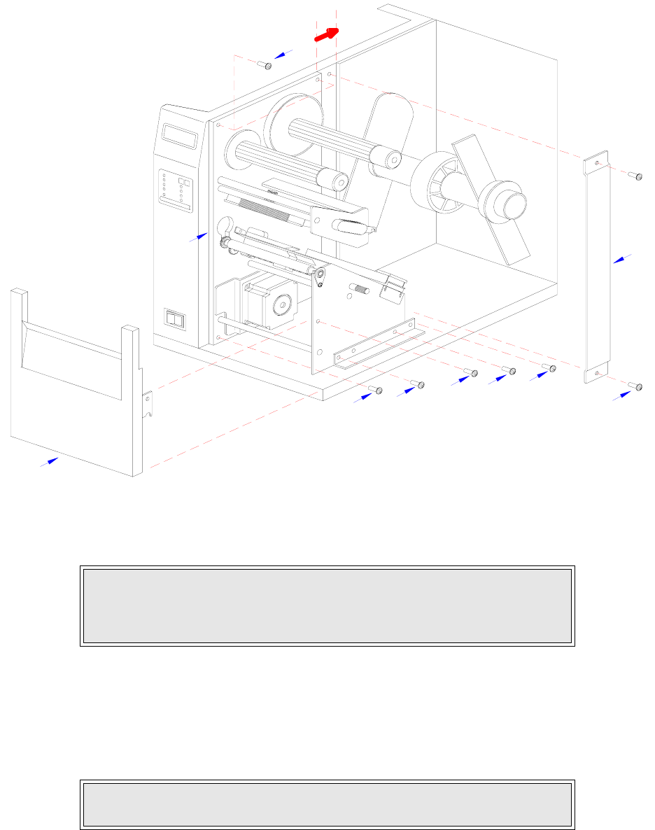
4 Remove screw (1, Figure 4-1a) securing front cover (2) to the printer frame. Lift away front
cover (2).
5 Remove two screws (3) to detach spacer panel (4). Lift away spacer panel (4).
6 Remove four screws (5) from back panel (6) and two screws (7) from side frame bracket (8)
to release the entire print mechanism.
Label Cutter Kit Label dispenser PCMCIA Memory Expansion
Flash Memory Expansion Real Time Clock Interface Module Upgrade
NOTE: Additional relative information may also be found in Figure 10-5,
Accessories & Sensors Location; Figure 10-6, Print Position Reference
Diagram; and Figures 10-12 through 10-15, Operation & Timing Charts of the
Diagrams & Schematics section.
NOTE: Figures 10-1, 10-2, and 10-3 in the Diagrams & Schematics section
provide guidance on housing cover, media, and ribbon removal respectively.
NOTE: The screw is accessible at the rear of the cover on the right side.
Manipulate the cover upward and outward to remove.
NOTE: The print mechanism will be all that is stainless steel or aluminum.
The print mechanism back plate is vertically arranged and reaches from the
very top down to the base.
Section 4: Accessories Installation
M84Pro Service Manual PN 9001111A Page 4-2
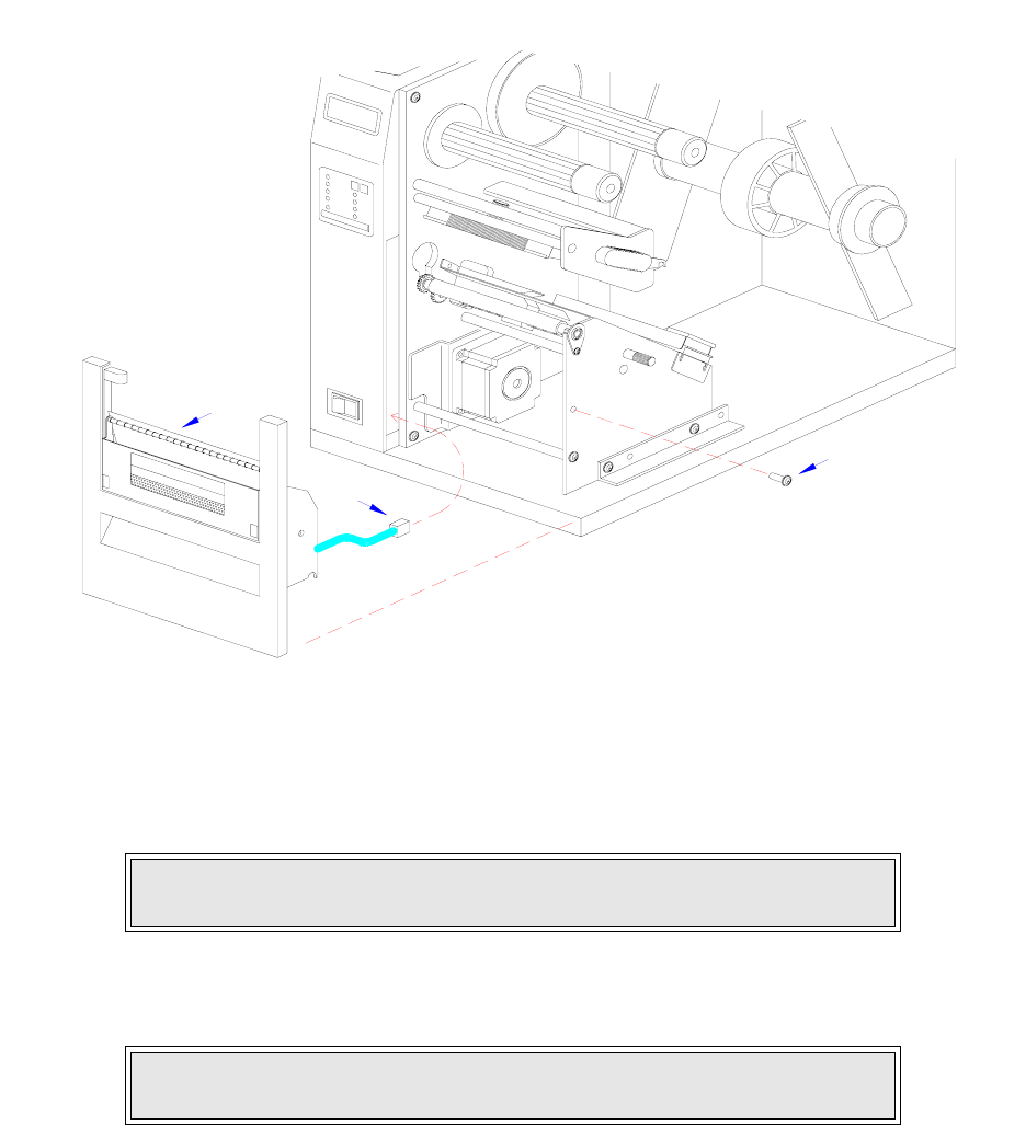
Figure 4-1a, Label Cutter Installation
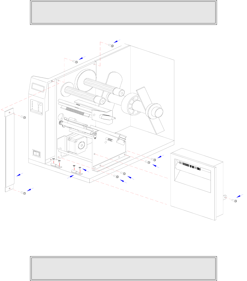
7 Slide entire print mechanism fully toward the rear.
8 Reapply two screws (7) to side frame bracket (8) and four screws (5) to back panel (6) to
secure print mechanism.
9 Attach two hinge halves (9, Figure 4-1b) to the front base of the printer using two screws
(10) for each.
10 Install spacer panel (4) into the void left in front of print mechanism and secure using two
screws (3).
CAUTION: ENSURE WIRING HARNESSES ARE NOT PINCHED WHEN
ADJUSTING THE PRINT MECHANISM. THE PRINT MECHANISM WHEN
ADJUSTED, WILL COVER THE VOID LEFT BY THE REMOVAL OF THE
SPACER PANEL.
NOTE: Before tightening the hinge screws, pull the hinges forward to align
them.
4
5
6
5
2
7
175
3
Section 4: Accessories Installation
M84Pro Service Manual PN: 9001111A Page 4-3
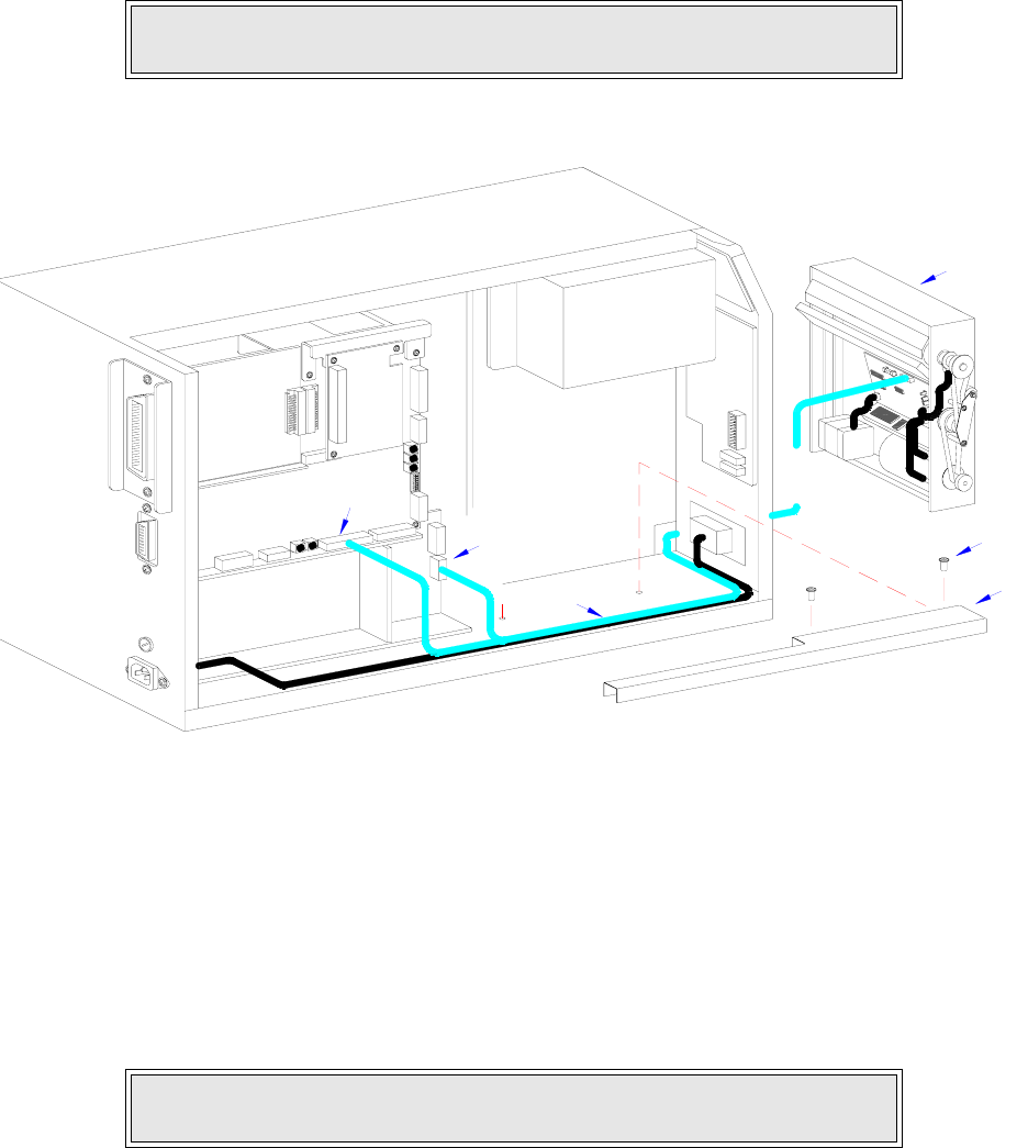
11 Route the single connector end of cutter wiring harness (11, Figure 4-1c) through the printer
side wall from the electric side to the mechanical side.
Figure 4-1b, Label Cutter Installation
12 Connect wiring harness (11) to cutter assembly (12), main circuit board board (13), and
power board (14).
13 Attach cutter assembly (11) to the printer base by connecting their respective hinge halves.
14 Remove two screws (15) securing cable shield (16).
15 Encase cutter wiring harness (11) with the power cable in cable shield (16) and secure
using two screws (15).
CAUTION: WHEN ROUTING THE WIRING HARNESS, ENSURE THAT IS
IS ROUTED IN A MANNER SO AS TO PREVENT PINCHING OR
INTANGLEMENTS.
NOTE: There is one small connector on the wiring harness that will remain
unconnected for cutter installation. Ensure the connectors are properly
oriented when mating. Equipment damage may occur otherwise.
10
5
3
9
7
7
5
5
1
5
4
Section 4: Accessories Installation
M84Pro Service Manual PN 9001111A Page 4-4
16 Place DSW3-1 in the up position and the DSW3-2 in the down position.
17 Load the printer with ribbon and media stock and close/install all housing covers.
18 Restore power and test cycle.
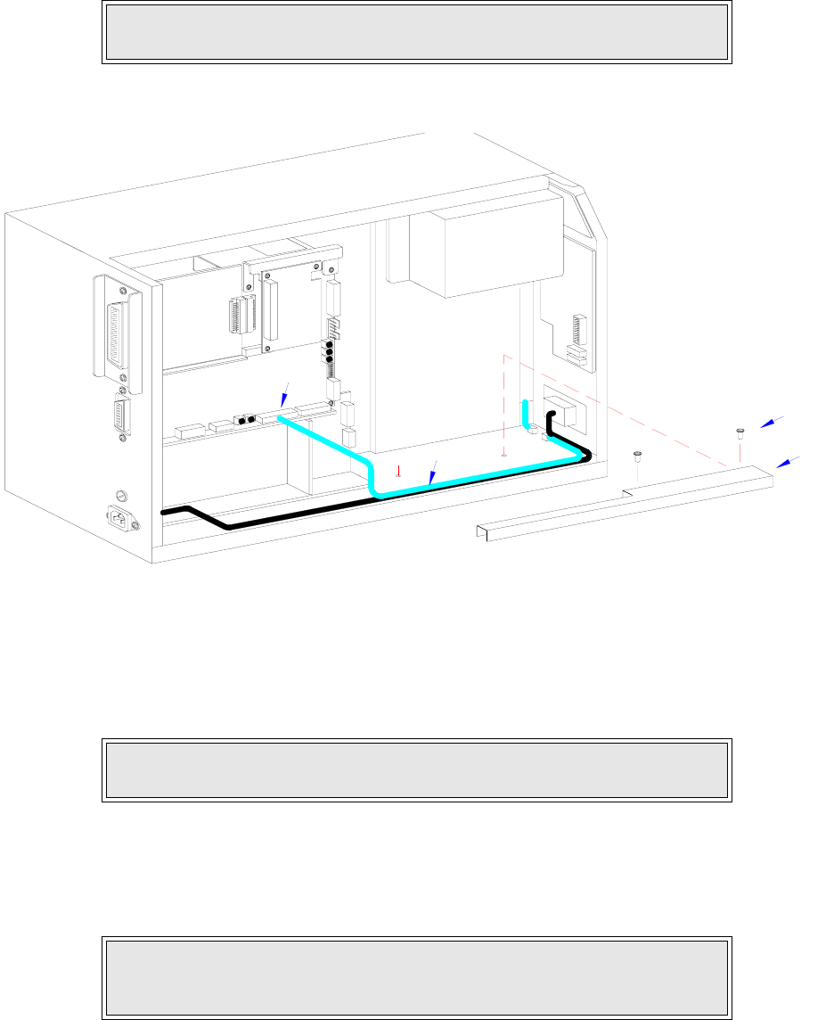
Figure 4-1c, Label Cutter Installation
DISPENSER INSTALLATION
Installation of the optional label dispenser into the printer adds the convenience of automatic
label dispensing. Each label is printed, then peeled from the backing paper and presented at the
front of the printer for removal by the operator. A photo-electric sensor detects the presence of a
completed label and signals the printer to automatically backfeed the label stock for correct
alignment of the next print cycle.
1 Switch off the printer and disconnect the power supply cord.
2 Open/remove the top, right, and left housing covers.
NOTE: Refer to Figures 10-1, 10-2, and 10-3 in the Diagrams & Schematics
section for housing cover, media, and ribbon installation respectively.
NOTE: Refer to Figure 10-5, Accessories & Sensors Location in the
Diagrams & Schematics section if assistance is needed.
INTERFACE
MAIN CIRCUIT BOARD
DAUGHTER
BOARD
POWER BOARD
BOARD
PANEL BOARD
LCD
BELT CONFIGURATION
15
16
12
13
11
14
Section 4: Accessories Installation
M84Pro Service Manual PN: 9001111A Page 4-5
3 Remove the ribbon and label stock if applicable and leave the print head open.
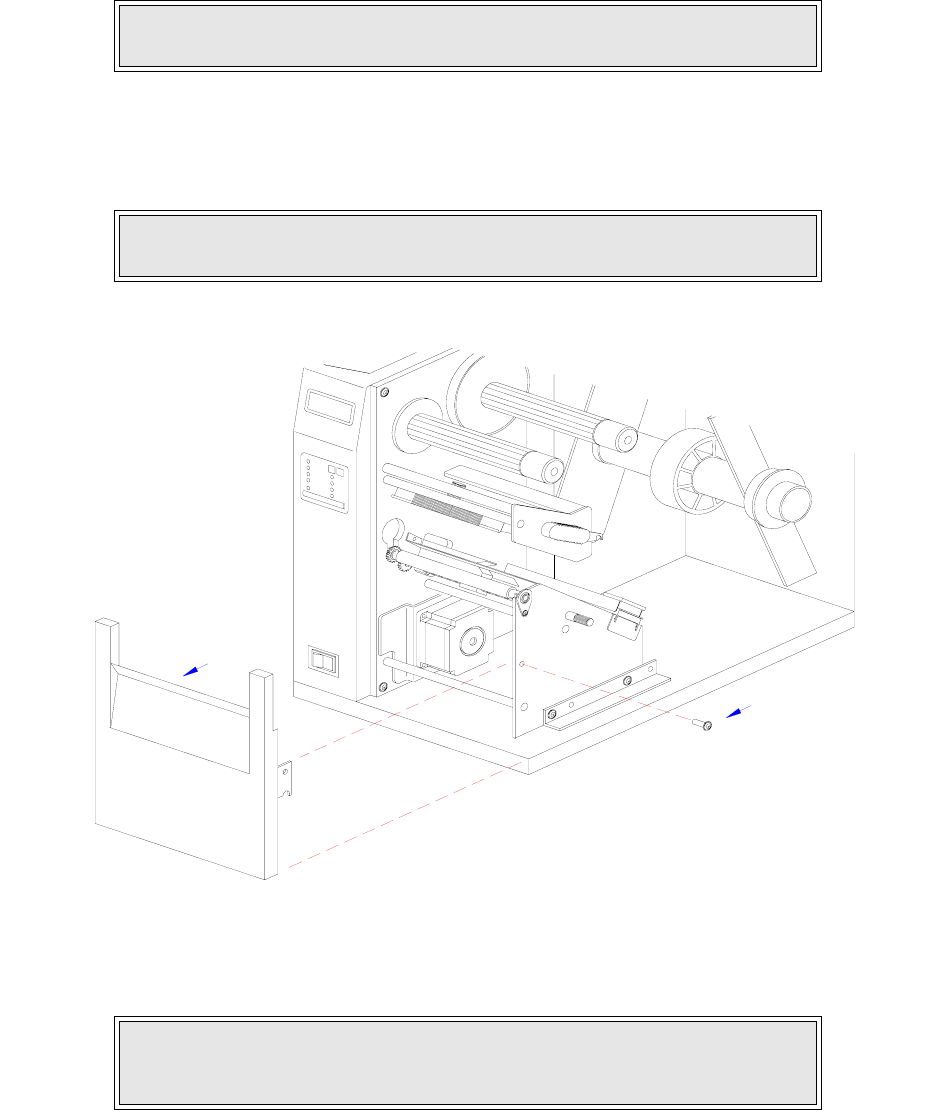
4 Remove screw (1, Figure 4-2a) securing front cover (2) to the printer frame. Lift away front
cover (2).
Figure 4-2a, Dispenser Installation
5 Route dispenser wiring harness (3) through the slot in the printer side wall.
NOTE: Figures 10-1, 10-2, and 10-3 in the Diagrams & Schematics section
provide guidance on housing cover, media, and ribbon removal respectively.
NOTE: The screws are accessible at the rear of the cover on the right side.
Manipulate the cover upward and outward to remove.
CAUTION: WHEN ROUTING THE WIRING HARNESS, ENSURE THAT IIS
ROUTED IN A MANNER SO AS TO PREVENT PINCHING OR
INTANGLEMENTS.
1
2
Section 4: Accessories Installation
M84Pro Service Manual PN 9001111A Page 4-6
Figure 4-2b, Dispenser Installation
6 Insert dispenser (4, Figure 4-2b) in place of removed front cover (2) and secure using
screw (1).
7 Connect dispenser wiring harness (3, Figure 4-2c) with free end of wiring harness con-
nected to CN10 port (5) of main circuit board.
8 Remove two screws (6) securing cable shield (7).
9 Encase cutter wiring harness (3) along with the power cable, in cable shield (7) and secure
using two screws (6).
10 Place the DSW3-1 and the DSW3-2 dip switches in the up position.
11 Load the printer with ribbon and media stock and close/install all housing covers.
NOTE: Dispenser installation will only require a single screw. Discard the
remaining screw from front cover removal.
CAUTION: ENSURE THE CONNECTORS ARE PROPERLY ORIENTED
WHEN MATING. EQUIPMENT DAMAGE MAY OCCUR OTHERWISE.
4
1
3
Section 4: Accessories Installation
M84Pro Service Manual PN: 9001111A Page 4-7
12 Restore power and test cycle.
Figure 4-2c, Dispenser Installation
FLASH MEMORY INSTALLATION
1 Switch off the printer and disconnect the power supply cord.
2 Open/remove the top, right, and left housing covers.
3 Remove three screws (1, Figure 4-3) securing daughter board (2) to main circuit board (3).
4 Disconnect daughter board (2) from circuit board (3).
5 Insert flash card (4) into its reserved brackets on main circuit board (3).
NOTE: Figures 10-1, 10-2, and 10-3 in the Diagrams & Schematics section
provide guidance on housing cover, media, and ribbon installation.
NOTE: Figure 10-1 in the Diagrams & Schematics section provides guidance
on housing cover removal.
NOTE: The flash card will properly insert into the connector bracket in a
single orientation. Ensure that the contactor side is goes first then press
inward to index the notched areas.
INTERFACE
MAIN CIRCUIT BOARD
DAUGHTER
BOARD
POWER BOARD
BOARD
PANEL BOARD
LCD
BELT CONFIGURATION
6
7
5
3
Section 4: Accessories Installation
M84Pro Service Manual PN 9001111A Page 4-8
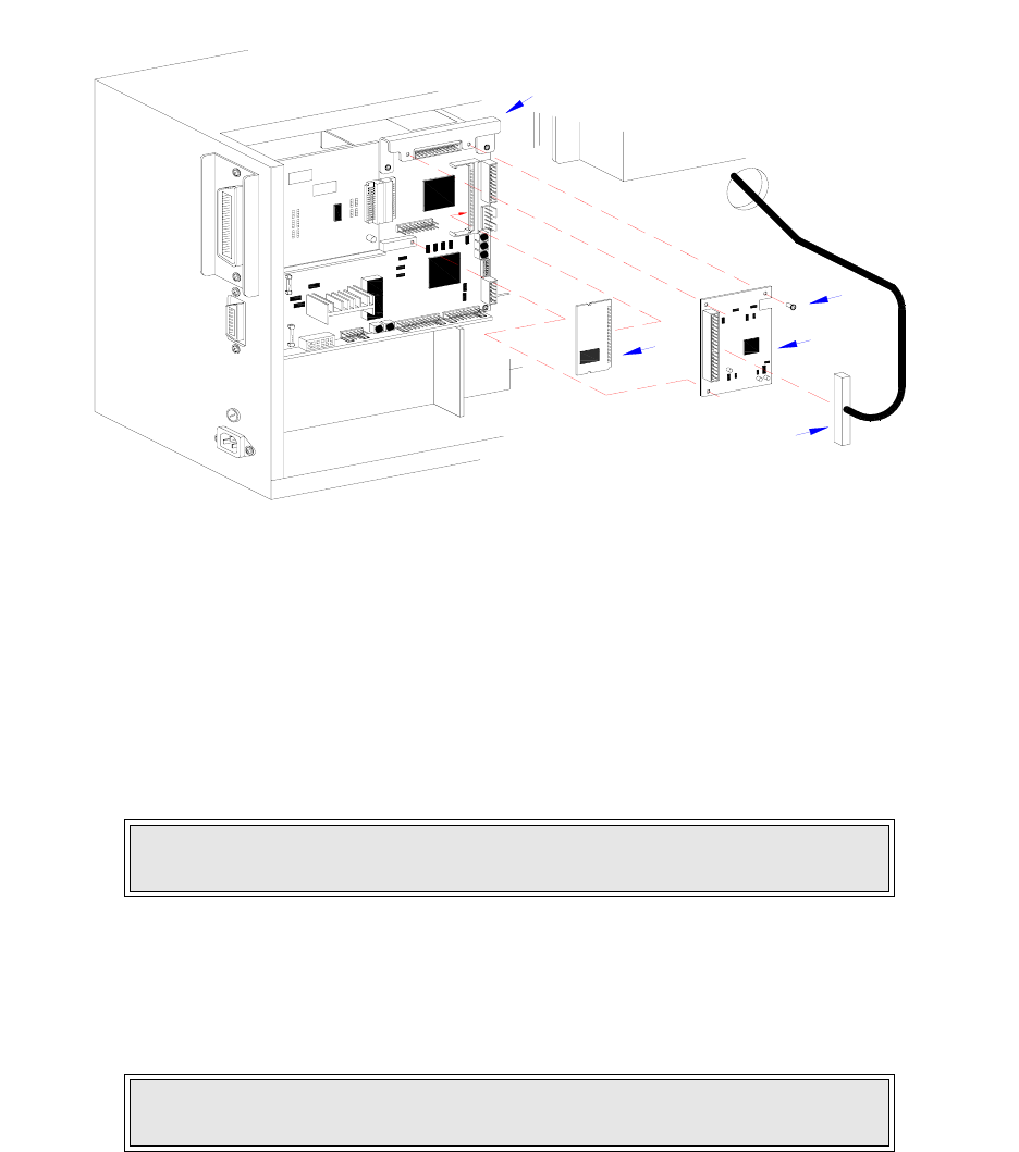
Figure 4-3, Flash Card Installation
6 Apply and connect daughter board (2) to main circuit board (3) and secure using three
screws (1).
7 Ensure power supply wiring harness (5) is fully connected to daughter board (2).
8 Factory Reset as directed in the Factory Reset section of this manual.
9 Restore power, test cycle, and replace covers.
PCMCIA MEMORY EXPANSION INSTALLATION
1 Switch off the printer and disconnect the power supply cord.
2 Open/remove the top, right, and left housing covers.
3 Remove two screws (1, Figure 4-4a) securing interface board (2) to the rear printer hous-
ing.
4 Withdraw interface board (2) from printer.
5 Remove two screws (3) securing main circuit board (4) to the rear printer housing.
6 Remove three screws (5) securing main circuit board (4) to the printer frame.
7 Manipulate main circuit board (4) from printer.
NOTE: Figure 10-1 in the Diagrams & Schematics section provides guidance
on housing cover installation.
NOTE: Figure 10-1 in the Diagrams & Schematics section provides guidance
on housing cover removal.
IEEE1284 + RS BOARD
1
2
3
5
4
Section 4: Accessories Installation
M84Pro Service Manual PN: 9001111A Page 4-9
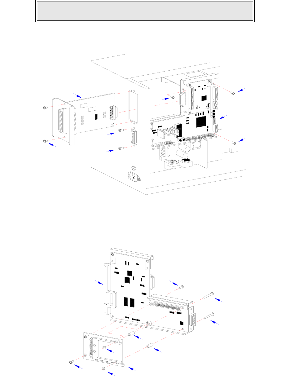
Figure 4-4a, Memory Expansion
8 Insert two long screws (6, Figure 4-4b) into main circuit board (4) from the front.
Figure 4-4b, Memory Expansion
NOTE: It is advised that all wiring harnesses remain connected during
expansion board instalation to prevent the possibility of incorrect connections.
IEEE1284 + RS BOARD
2
1
5
5
5
3
3
4
7
6
9
10 8
6
410
9
7

Section 4: Accessories Installation
M84Pro Service Manual PN 9001111A Page 4-10
9 Insert a standoff (7) onto each screw (6) from the back side of main circuit board (4).
10 Connect expansion board (8) to the back side of main circuit board (4).
11 Apply a nut (9) to the end of each screw (6). Tighten securely.
12 Apply a screw (10) into the lower left corner of expansion board (8). Tighten securely.
13 Apply a screw (10) into the front of main circuit board (4) to secure the upper left corner of
expansion board (8). Tighten securely.
14 Insert main circuit board (4, Figure 4-4a) into the printer and secure using three screws (5)
and two screws (3).
15 Insert interface board (2) into its respective slot to connect with main circuit board (4) and
secure using two screws (1).
16 Restore power, test cycle, and install housing covers.
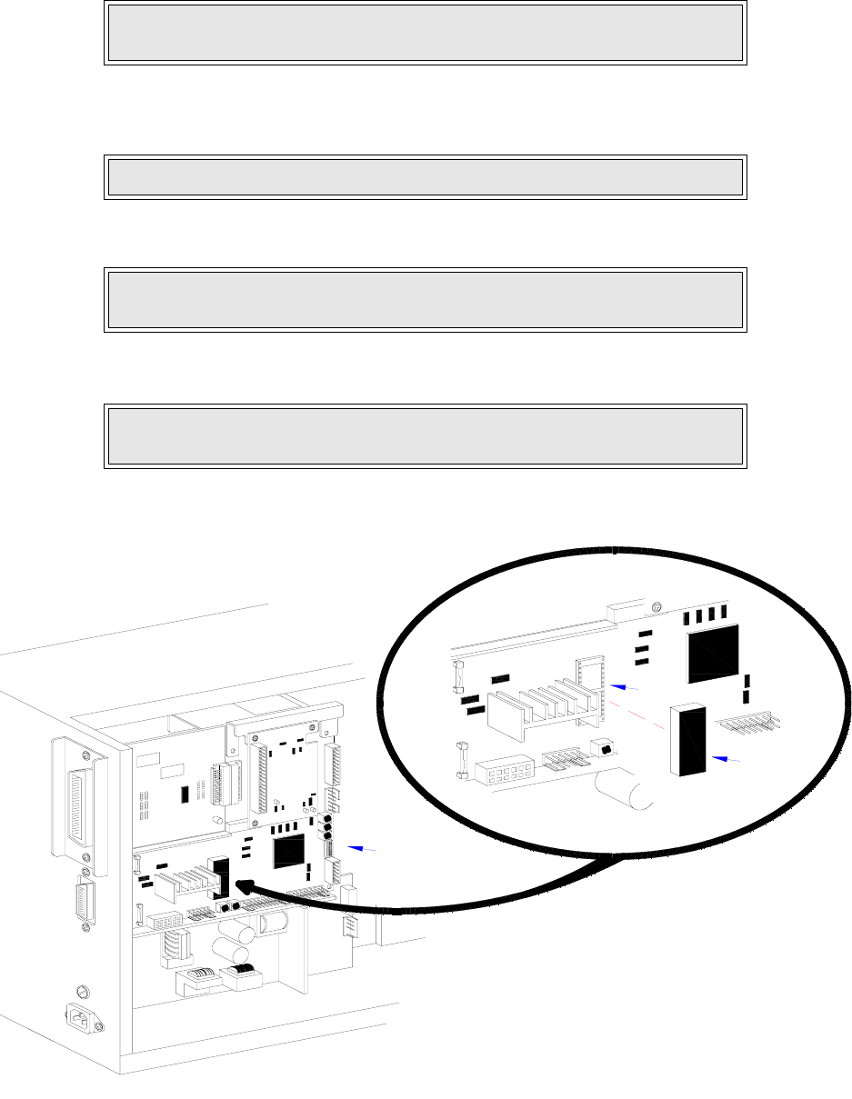
REAL-TIME CLOCK INSTALLATION
The real time clock chip allows the date and time to be maintained in the local printer rather than
using the system clock. It consists of a special clock chip that replaces the EEPROM chip on the
main cicuit board.
1. Switch the printer off and disconnect the power supply cord.
2 Remove the left side housing cover to gain access to the main circuit board.
3 Locate and withdraw the EEPROM chip (1, Figure 4-5) from main circuit board (2).
4 Insert clock chip (3) into the vacant connection recepticle (4).
5 Connect the power supply cord.
6 Factory Reset as directed in the Factory Reset section of this manual.
7 Press and hold the LINE key while simultaneously switching the power on.
8 When the printer emits one long beep, release the LINE key.
9 Press the FEED key 11 times to display the prompt to set the calender.
NOTE: Figure 10-1 in the Diagrams & Schematics section provides guidance
on housing cover installation.
CAUTION: IF USING A TOOL TO REMOVE THE EEPROM CHIP, ENSURE
THAT IT IS NOT BEING INSERTED BETWEEN THE RECEPTACLE BOARD
AND THE CIRCUIT BOARD. DESTRUCTION IN THE CIRCUIT BOARD
WILL OCCUR. INSERT THE TOOL BETWEEN THE TWO PIECES OF
BLACK PHENOLIC MATERIAL TO PRY THE CHIP FREE.
LCD DISPLAY: INITIALING ROM V00.00.00.00
LCD DISPLAY: ADVANCED MODE
Section 4: Accessories Installation
M84Pro Service Manual PN: 9001111A Page 4-11
10 Press the LINE key to move the cursor under the yes option, then press FEED to select.
11 Enter all of the date data required for calender operation.
12 Verify proper operation and replace housing covers.
Figure 4-5, Real-Time Clock Installation
LCD DISPLAY: SET CALENDER
YES NO
LCD DISPLAY: CALENDER 00/00/00 00:00
NOTE: Press the LINE key to scroll through the numeral options and the
FEED key to move the cursor laterally for each date entry.
NOTE: Figure 10-1 in the Diagrams & Schematics section provides guidance
on housing cover installation.
IEEE1284 + RS BOARD
4
1,
2
3
Section 4: Accessories Installation
M84Pro Service Manual PN 9001111A Page 4-12
INTERFACE MODULE UPGRADE
The printer is typically ordered with a high-speed parallel interface card installed. However,
interface requirements sometimes change and an upgrade is desired. All of the interface cards
are installed within the same slot located in the rear of the printer with little or no difference in
installation methodology. Refer to the Interface Board procedure of the Replacement Procedures
section for specific directions for this upgrade.
M84Pro Service Manual PN: 9001111A Page 5-1
5
PRINTER CONFIGURATION
This section provides configuration instructions. Figures 10-7 through 10-19 in the Diagrams &
Schematics section provides diagrams and charts on print operation sequence.
DIP SWITCH PANELS
There are two DIP switches (DSW2 and DSW3) located on the front panel under a protective
cover. A third DIP switch is located on the RS232C Serial Adapter card and is used to set the
RS232C transmit/receive parameters. Each switch is an eight section on/off toggle type switch.
The ON position is always oriented upward and consequently, the off is always downward.
Switch settings are read by the printer electronics during the power up sequence and will not
become effective until the power is cycled.
RS232 TRANSMIT/RECEIVE SETTING
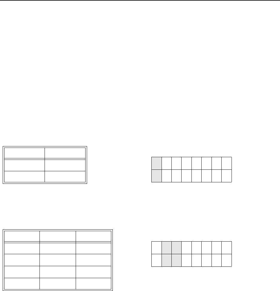
Data Bit Selection (DSW1-1): Sets the printer to receive either 7 or 8 data bits for each byte
transmitted.
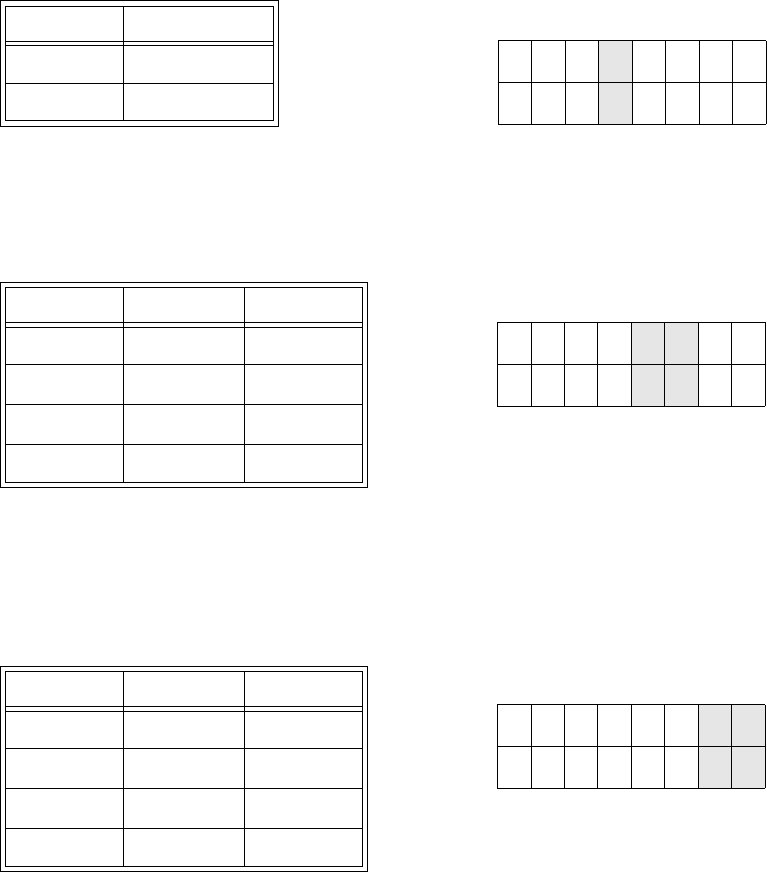
Parity Selection (DSW1-2, DSW1-3): Selects the type of parity used for error detection.
DSW1-1 SETTING
Off 8 Data Bits
On 7 Data Bits
DSW1
ON
OFF
12345678
DSW1-1 DSW1-3 SETTING
Off Off No Parity
Off On Even
On Off Odd
On On Not Used
DSW1
ON
OFF
12345678
Section 5: Printer Configuration
M84Pro Service Manual PN: 9001111A Page 5-2
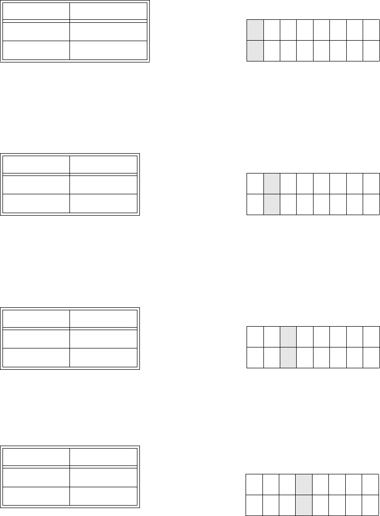
Stop Bit Selection (DSW1-4): Selects the number of stop bits to end each byte transmission.
Baud Rate Selection (DSW1-5, DSW1-6): Selects the data rate (bps) for the RS232 port.
Protocol Selection (DSW1-7, DSW1-8): Selects the flow control and status reporting protocols.
Refer to the Interface Specifications section in this manual for more information. (* Will select the
Status 2 protocol if DSW2-8 is ON).
DSW1-4 SETTING
Off 1 Stop Bit
On 2 Stop Bits
DSW1
ON
OFF
12345678
DSW1-5 DSW1-6 SETTING
Off Off 9600
Off On 19200
On Off 38400
On On 57600
DSW1
ON
OFF
12345678
DSW1-7 DSW1-8 SETTING
Off Off Rdy/Bsy
Off On Xon/Xoff
On Off Bi-Com 3
On On Bi-Com 4
DSW1
ON
OFF
12345678
Section 5: Printer Configuration
M84Pro Service Manual PN 9001111A Page 5-3
PRINTER SET UP
Print Mode Selection (DSW2-1): Selects between direct thermal printing and thermal transfer
printing.
Sensor Type Selection (DSW2-2): Selects between the use of a transmissive label gap or a
reflective eye-mark sensor.
Head Check Selection (DSW2-3): When selected, the printer will check for head elements that
are electrically malfunctioning.
Hex Dump Selection (DSW2-4): Selects Hex Dump mode.
DSW2-1 SETTING
Off Therm Xfr
On Direct Therm
DSW2
ON
OFF
12345678
DSW2-2 SETTING
Off Gap
On Eye-Mark
DSW2
ON
OFF
12345678
DSW2-3 SETTING
Off Disabled
On Enabled
DSW2
ON
OFF
12345678
DSW2-4 SETTING
Off Disabled
On Enabled
DSW2
ON
OFF
12345678
Section 5: Printer Configuration
M84Pro Service Manual PN: 9001111A Page 5-4
Receive Buffer Selection(DSW2-5): Selects the operating mode of the receive buffer. Refer to
the Interface Specifications section of this manual for more information.
If a 10/100BaseT LAN card is installed, DS2-5 has the following definitions:
Firmware Download (DSW2-6): Places the printer in the Firmware Download mode for
downloading new firmware into flash ROM.
Protocol Code Selection (DSW2-7): Selects the command codes used for protocol control.
Refer to the Selecting Protocol Control Codes section of the Technical Reference manual for
additional information.
.
DSW2-5 SETTING
Off Single Job
On Multi Job
DSW2
ON
OFF
12345678
DSW2-5 SETTING
Off ENQ Response
On Periodic Response
DSW2-6 SETTING
Off Disabled
On Enabled
DSW2
ON
OFF
12345678
DSW2-7 SETTING
Off Standard
On Non-Std
DSW2
ON
OFF
12345678
Section 5: Printer Configuration
M84Pro Service Manual PN 9001111A Page 5-5
Status Select(DSW2-8): For emulating earlier series software commands. Should be used only
if problems are encountered when using existing software. This switch will also affect the settings
selected by DSW1-7 and DSW1-8.
Backfeed Sequence (DSW3-1, DSW3-2): Backfeed is used to correctly position the label for
application and then retract the next label to the proper print position. This operation can be
performed immediately after a label is printed and used, or immediately prior to the printing of the
next label.
Label Sensor Selection (DSW3-3): Enables or disables the Label Sensor. If the Sensor is
enabled, it will detect the edge of the label and position it automatically. If it is disabled, the
positioning must be under software control using Line Feed commands.
DSW2-8 SETTING
Off Status 3 & 4 Enabled
On Status 2 & 3 Enabled
DSW2
ON
OFF
12345678
DSW3-1 SETTING
Off Off Continuous
Off On Tear-Off
On Off Cutter*
On On Dispenser
* Defaults to Continuous if cutter not
installed
DSW3
ON
OFF
12345678
DSW3-3 SETTING
Off Sensor Used
On Not Used
DSW3
ON
OFF
12345678
Section 5: Printer Configuration
M84Pro Service Manual PN: 9001111A Page 5-6
Back-Feed Selection (DSW3-4): When Back-Feed is enabled, the printer will position the last
printed label for dispensing and retract it before printing the next label. The amount of backfeed
offset is adjustable.
External Signal Interface: Refer to the Interface Specifications section for information on
External Signals.
EXT Print Start Signal Selection (DSW3-5): Allows an external device to initiate a label print for
synchronization with the applicator or other external device. When DSW3-5 is On, the unit is in
the Continuous print mode, Backfeed is disabled and External Signals are ignored.
External Signal Type Selection (DSW3-6, DSW3-7): Both the polarity and signal type (level or
pulse) of the external print synchronizing signal can be selected.
DSW3-4 SETTING
Off Enabled
On Disabled
DSW3
ON
OFF
12345678
DSW3-5 SETTING
Off Disabled
On Enabled
DSW3
ON
OFF
12345678
DSW3-6 DSW3-7 SETTING
Off Off Type 4
Off On Type 3
On Off Type 2
On On Type 1
DSW1
ON
OFF
12345678
Section 5: Printer Configuration
M84Pro Service Manual PN 9001111A Page 5-7
Repeat Print via External Signal (DSW3-8): Allows the applicator or other external device to
reprint the current label in the print buffer.
DEFAULT SETTINGS
All switches are placed in the Off default position for shipping. This will result in the following
operating configuration:
SOFTWARE DEFAULT SETTINGS
The printer stores the software settings upon receipt and uses them until they are again changed
by receipt of a command containing a new setting. These settings are stored in non-volatile
memory and are not affected by powering the printer off. The printer may be reset to use the
default software settings by depressing the LINE and FEED keys simultaneously while powering
the printer on. This will result in the following default configuration.
DEFAULT SETTINGS
Communications 8 data bits, no parity, 1 Stop bit, 9600 Baud
Protocol: Ready/Busy
Sensor Gap Sensor
Receive Buffer Multi Job
Mode Batch/continuous
Label Sensor Sensor Used
Backfeed Enabled
External Signals Enabled
SOFTWARE DEFAULT SETTINGS
Print Darkness 3
Print Speed 6 Inches Per Second (3 for M84Pro-6)
Print Reference Vertical = 0000, Horizontal = 0000
Print Offset +0
Zero No Slash
Ignore CR/LF Disabled
Character Pitch Proportional
Auto On Line Enabled
Feed on Error Enabled
DSW3-8 SETTING
Off Disabled
On Enabled
DSW3
ON
OFF
12345678
Section 5: Printer Configuration
M84Pro Service Manual PN: 9001111A Page 5-8
Once the default operation is complete, a DEFAULT COMPLETED message will be displayed on
the LCD panel. The printer should be powered off while this message is being displayed (or after
the beep is heard. This saves the default settings in the non-volatile memory where they will be
automatically loaded the next time the printer is powered on.
POTENTIOMETER ADJUSTMENTS
PITCH
After the pitch has been set with the LCD Control Panel, it is sometimes desirable to make minor
adjustments. This can be done using the PITCH potentiometer on the top panel. This
potentiometer is set at the factory so that it has a range of +/- 3.75 mm. The midpoint setting
should have no effect on the pitch. Turning the potentiometer all the way clockwise should move
the print position 3.75 mm up towards the top edge of the label. Turning it all the way
counterclockwise should move the print position down 3.75 mm.
1. Press and hold the FEED key while switching the power switch on.
2. Release the FEED key upon hearing a beep from the printer.
3. Use the Cursor keys to step to the desired option and press the ENTER key to select.
4. Use the Cursor keys to step to the test label size and press the ENTER key to select.
5. Standby for the printer to begin printing test labels continuously.
6. Adjust the PITCH potentiometer until the first print position is at the desired location on the
label.
7. Press the FEED key to cease printing when complete.
8. Power the printer off and then back on, to exit the test label mode.
Feed Reprint Disabled
Priority Command
Language English
CC1 Mem Select Card
Eurocode D5H
DEFAULT COMPLETED
NOTE: Adjusting the PITCH potentiometer will affect the stop position of the
label.
NOTE: The LCD display will inquire what type of test label is desired.
NOTE: If the potentiometer does not have enough range, it will be necessary
to change the pitch setting using the front panel display.
SOFTWARE DEFAULT SETTINGS

Section 5: Printer Configuration
M84Pro Service Manual PN 9001111A Page 5-9
BACKFEED OFFSET
When a label is printed it must be correctly positioned for dispensing and application. Thusly, the
printer advances the label stock sufficiently for the printed label to be dispensed. After the label
has been removed for application, the label stock must be withdrawn back into label printing
position. The backfeed function repositions the label stock for printing.
The Backfeed function is enabled if DSW3-4 is in the Off position. When enabled, placing DSW3-
1 in the Off position will cause the backfeed operation to be performed immediately before each
label is printed. If DSW3-1 is in the On position, the backfeed operation is performed as soon as
the dispensed label has been printed and taken from the printer.
The amount of backfeed is controlled by the OFFSET potentiometer on the DIP Switch Panel
inside the cover. The full adjustment range is +/- 3.75 inches from nominal. The backfeed
adjustment procedure is as follows:
1. Turn the printer on.
2. Press the LINE key to place the printer in the Off-Line status.
3. Press the FEED key to feed out a blank label while observing the dispensement position.
4. Adjust the OFFSET potentiometer on the front control panel as deemed necessary.
5. Repeat steps 4 and 5 until a label is fully released from the liner.
DISPLAY
This potentiometer is used to adjust the contrast of the LCD display for optimum viewing under
various lighting conditions.
PRINT
The PRINT potentiometer is used to adjust the amount of heat (i.e., power) applied to the head
for printing. It provides a continuous range of adjustment. Maximum print darkness is obtained by
turning the potentiometer all the way clockwise and a maximum counterclockwise setting will give
the lightest print.
LCD PANEL PRINTER CONFIGURATION
The LCD Panel allows the printer to communicate with the operator. The operator communicates
with the printer largely through the use of the LINE and FEED keys. Many settings may also be
controlled via software commands. Where software commands and control panel settings
conflict, the printer will always use the last valid setting.
There are seven modes of operation. To enter the desired mode, the KEY SEQUENCE
combination listed in the table below must be performed. The initial LCD display message is
shown for each mode.
NOTE: Adjustment of the PRINT potentiometer will affect the darkness in all
of the command code, speed, and darkness ranges.
Section 5: Printer Configuration
M84Pro Service Manual PN: 9001111A Page 5-10
CONFIGURATION MODES
MODE KEY SEQUENCE INITIAL DISPLAY
Normal POWER ONLINE QTY:000000
Advanced LINE + POWER ADVANCED MODE
Test Print FEED + POWER TEST PRINT MODE
CONFIGURATION
Default Setting LINE + FEED + POWER DEFAULT SETTING YES NO
Clear Non-Standard Protocol DSW2-7 ON + LINE + FEED + POWER ALT. PROTOCOL
Protocol Code Download DSW2-7 ON + POWER + LINE USER DOWNLOAD
Hex Dump DSW2-4 ON + POWER ONLINE QTY: 000000
NORMAL MODE
The printer initially powers on in the ONLINE mode. The user can access the User Settings using the
following procedures.
LCD DISPLAY DEFINITION
V 05.00.03.00
INITIALIZING
Displays the firmware during the initialization.
ONLINE
QTY:000000
The LCD will display the ONLINE status on the top line and the label quantity
(QTY) status on the bottom. The message will be changed to OFFLINE
whenever the printer is switched offline by pressing the LINE key. When a
print job is received, the quantity line will indicate the number of labels to be
printed. As the label job prints, the display will indicate the number of labels in
the print job that remains to be printed.
OFFLINE
000000
Press the LINE key once. When the display changes to OFFLINE, press the
FEED and LINE keys simultaneously for more than one second and release.
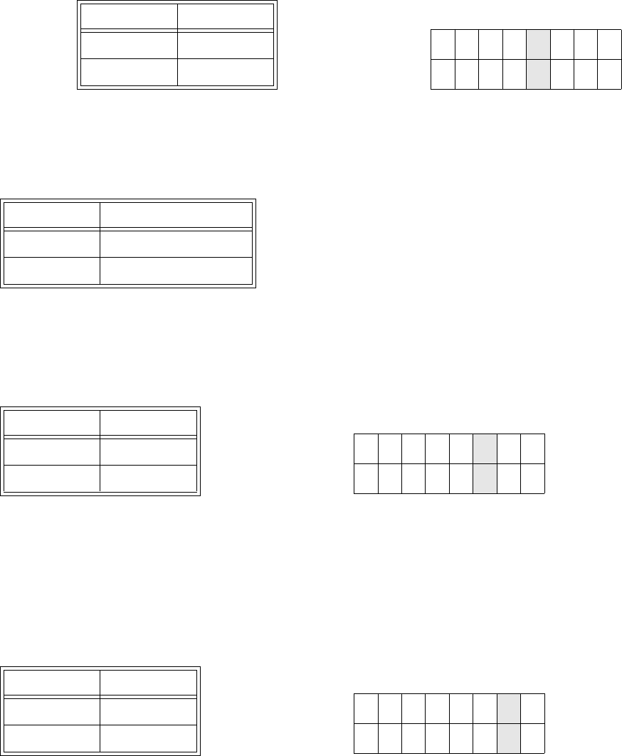
PRINT DARKNESS
12 345
The LCD now displays the Print Darkness selections. The current setting is
indicated by a cursor over one of the range settings. There are 5 possible
selections. The lowest setting represents the lightest print and the highest
setting the darkest print.
1. Press the Cursor keys to step the cursor to the desired option.
2. Press the ENTER key to select the option and advance to the next display
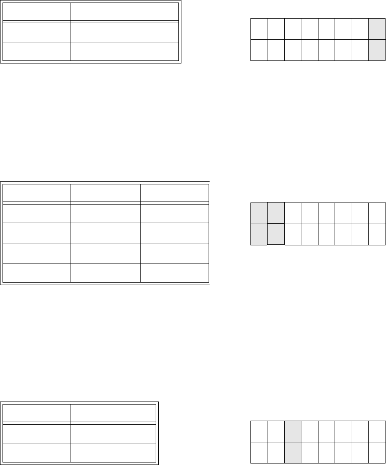
PRINT SPEED
2 4 6 8 10
The current setting is indicated by the cursor.
1. Use the Cursor keys to step the cursor to the desired option.
2. Press the ENTER key to select the option and advance to the next display
Section 5: Printer Configuration
M84Pro Service Manual PN 9001111A Page 5-11
PITCH OFFSET
+ 00mm
The label Pitch is the distance from the leading edge (the edge that comes out
of the printer first) of a label and the leading edge of the next label. The
leading edge position of the label can be adjusted relative to the print head +/-
49 mm in increments of 1mm. Once the position is set, it can be fine adjusted
+/- 3.75 mm using the PITCH potentometer.
1. The cursor will initially be positioned over the Pitch Direction setting. Use
the LINE key to step to the positive (+) or negative (-) selection. A positive
selection moves the leading edge of the label forward (away from the print
head) while a negative selection moves the leading edge of the label back
into the mechanism.
2. Press the FEED key to select the option and advance the cursor to the
Offset selection.
3. Use the CURSOR keys to step the first digit of the counter to the desired
option. The display will increment one step each time the Cursor keys are
pressed. The maximum setting is 5.
4. Press the FEED key to select the option and advance the cursor to the
second digit. Again use the CURSOR keys to step to the desired option.
5. Press the FEED key to select the option and advance to the next display
6. Print a test label after completing the adjustments to ensure they are
correct.
CANCEL PRINT JOB
YES NO
Selecting the YES option will cause all print jobs to be cleared and not
recovered. The default option is NO.
1. Use the Cursor keys to step the cursor to either the YES or NO option.
2. Press the ENTER key to select the option and advance to the next display
CANCEL PRINT JOB
COMPLETED
The printer will beep 3 times and the display will appear for 3 seconds before
returning to the initial On-Line Normal Mode after the print jobs are cleared.
The printer must be taken off-line and the user settings must be re-entered to
change any of the settings.
ADVANCED MODE
An Advanced Mode is provided to make adjustments that require only occasional changes. Since they
affect the basic operation of the printer, the procedure for entering this mode is designed to prevent
someone from accidently changing the settings.
LCD DISPLAY DEFINITION
V 05.00.03.00
INITIALIZING
Displays the firmware during the initialization.
ADVANCED MODE Press and hold the LINE key while switching the power switch On. Release
the LINE key when the printer emits one long beep. Press FEED.
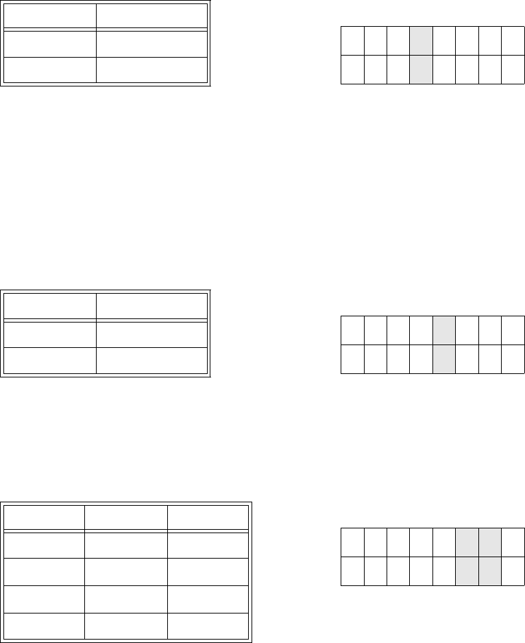
DARKNESS RANGE
A B
This setting allows the selection of darkness ranges. Option B is the darker
image of the two. Use the LINE key to move the cursor to the desired option
and press the FEED key to select.
LCD DISPLAY DEFINITION

Section 5: Printer Configuration
M84Pro Service Manual PN: 9001111A Page 5-12
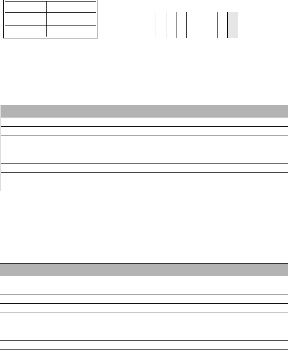
ZERO SLASH
YES NO
This setting determines if a zero is printed with or without a slash. This setting
can also be controlled via software commands. When YES is selected, the
printer internal fonts will have a slash through the center of the zero character.
1. Use the LINE key to step the cursor to either the YES or NO option.
2. Press the FEED key to select the option and advance to the Auto Online
display.
AUTO ONLINE
YES NO
This setting determines the mode in which the printer powers up. If YES is
selected, the printer powers up in the ON-LINE mode and is ready to print. If
NO is selected, the printer powers up in the OFF-LINE mode and must be
manually placed in the ON-LINE mode by pressing the LINE key before it is
ready to print.
1. Use the LINE key to step the cursor to either the YES or NO option.
2. Press the FEED key to select the option and advance to the Print Offset
display.
PRINT OFFSET
V:+0000 H:+0000
Vertical Offset is the distance down from the leading edge (the edge of the
label that comes out of the printer first) to the first vertical print position. A
positive setting moves the label edge out of the printer while making it
negative moves it back into the printer. Horizontal Offset is the distance that
the label image is shifted either to the right or left on the label. The image is
shifted to the left (towards the inside edge of the label) for a positive setting
and it is shifted to the right (towards the outside edge of the label) for a
negative setting. This setting changes the base reference point for all
subsequent label jobs. It’s effect is identical to the <ESC>A3 Base Reference
point command. Since the printer moves the label in discrete steps equal to
the size of the print dot, the units of measure for Vertical and Horizontal Offset
distance is dots. The maximum values that can be set is 3600 for vertical
offset and 3199 for horizontal. If the allowable limit is exceeded, the printer will
not accept the selection.
1. Use the LINE key to step the cursor to the desired option. The display will
increment one step for each time a LINE key is pressed.
2. Press the FEED key to select the option and advance to the next display
3. Repeat step 1 and 2 for character requirement.
4. Press the ENTER key to select the option and advance to the next display
Note: This setting can be overriden by the Base Reference Point Command.
SET CALENDAR
YES NO
The Calendar is a optional feature in the M10e printer allowing the date and
time to be set manually using the LCD Display or via the <ESC>WT Calendar
Set command. This screen will not be displayed if the Calendar Option is not
installed. The last setting (manual or software command) received by the
printer will be the value used. The format of the display is YY/MM/DD hh:mm
(Year/Month/Day/hours:minutes). The date format is fixed and cannot be
changed. This display will only appear if the Calendar Option has been
installed.
1. Press the LINE key to step the cursor to either the YES or NOoption. The
YES option will enable the Calendar feature and NO will disable.
2. Press the FEED key to select the option and advance to the next display
LCD DISPLAY DEFINITION
Section 5: Printer Configuration
M84Pro Service Manual PN 9001111A Page 5-13
CALENDAR
00/00/00 00:00
1. Year - Press the LINE key to increase and the FEED key to decrease the
character value to the desired option. The first display shown will have the
cursor over the two digit year selection. Press the Enter key to select the
option and advance to the Month position.
2. Month - Press the LINE key to increase and the FEED key to decrease
the character value to the desired option. Press the Enter key to select the
option and advance to the Day position.
3. Day - Press the LINE key to increase and the FEED key to decrease the
character value to the desired option. Press the Enter key to select the
option and advance to the Hour position.
4. Hour - Press the LINE key to increase and the FEED key to decrease the
character value to the desired option. The entry must coorespond with a
24 hour day. Press the Enter key to select the option and advance to the
Hour position.
5. Minute - Press the LINE key to increase and the FEED key to decrease
the character value to the desired option. Press the Enter key to select the
option and advance to the Ignore CR/LF display.
IGNORE CR/LF
YES NO
This selection tells the printer to strip out all carriage return/line feed pairs
(CR/LF ) from the data stream, including graphics and 2D bar codes. It is used
primrily to maintain compatibility with earlier models of SATO printers.
1. Use the LINE key to step the cursor to either the YES or NO option.
2. Press the FEED key to select the option and advance to the Character
Pitch display.
CHARACTER PITCH
PROP FIXED
This selection allows the default character pitch to either be set for fixed
character spacing or proportional character spacing.
1. Use the LINE key to step the cursor to the desired option.
2. Press the FEED key to select the option and advance to the Advanced
Mode display.
ADVANCED MODE To exit the Advanced mode, power the printer off and then back on.
CARD MODE
The Card Mode is entered from the Advanced Mode display. The Card Mode allows the operator to
manage the Expanded Memory (PCMCIA Card or Internal Expanded Flash ROM).
LCD DISPLAY DEFINITION
V 05.00.03.00
INITIALIZING
Displays the firmware during the initialization.
ADVANCED MODE The Card Mode is entered from the Advanced Mode display by pressing the
right LINE key once.
CARD MODE The Card Mode display indicates that the printer is in the Card Mode. To
advance to the first selection, press the FEED key.
LCD DISPLAY DEFINITION

Section 5: Printer Configuration
M84Pro Service Manual PN: 9001111A Page 5-14
MEM SELECT (CC1)
CARD MEMORY
This selection determines which type of optional expanded memory will be
addressed as “CC1" in the command streams. The CARD selection specifies
the optional PCMCIA card as CC1 and the optional Expanded Flash ROM as
CC2. The Memory selection specifies the optional Expanded Flash ROM as
CC1 and the optional PCMCIA card as CC2.
1. Use the LINE key to step the cursor to the desired option.
2. Press the FEED key to select the option and advance to the next display
CARD->MEMORYCOPY
TRUETYPEFONT Y/N
This selection allows TrueType fonts to be copied from the PCMCIA Memory
card installed in the Memory Card slot.
1. Use the LINE key to step the cursor to desired option. If Yes is selected,
the printer will enter the Card Copy mode. If No is selected, the display will
advance to the Card to Memory SATO Font Copy mode.
COPY START
YES NO
2. Confirm the selection by stepping the cursor to the Yes option. If No is
selected, the display will return to the previous selection.
TRUETYPEFONTCOPY
COPYING
3. Press the FEED key to select the option. If Yes was selected the copy
process will begin.
TRUETYPE FONTCOPY
COMPLETED
4. Once the copy process is completed, press the FEED key to step the
display.
CARD COPY/FORMAT
XXXXXXX ERROR
5. If an error is encountered in the copy process, one of the following
messages will be displayed on the second line:
R/W Error Indicates a Read/Write error occured
No Card Error Indicates no card was recognized
Mem Full Error Indicates that there is insufficient memory
available.
CARD->MEMORYCOPY
SATOFONT Y/N
This selection allows SATO fonts to be copied from the PCMCIA Memory card
installed in the Memory Card slot.
1. Use the LINE key to step the cursor to desired option. If Yes is selected,
the printer will enter the Card Copy mode. If No is selected, the display will
advance to the Card to Memory Copy All mode.
COPY START
YES NO
2. Confirm the selection by stepping the cursor to the Yes option. If No is
selected, the display will return to the previous selection.
SATO FONT COPY
COPYING
3. Press the FEED key to select the option. If Yes was selected the copy
process will begin.
SATO FONT COPY
COMPLETED
4. Press the FEED key to advance to next display.
CARD COPY/FORMAT
XXXXXXX ERROR
5. If an error is encountered in the copy process, one of the following
messages will be displayed on the second line:
R/W Error Indicates a Read/Write error occured
No Card Error Indicates no card was recognized
Mem Full Error Indicates that there is insufficient memory
available.
LCD DISPLAY DEFINITION

Section 5: Printer Configuration
M84Pro Service Manual PN 9001111A Page 5-15
MEMORY->CARDCOPY
ALL <0MB> Y/N
This selection allows the entire contents from the optional Expanded Memory
to be copied to the PCMCIA Memory card installed in the Memory Card slot.
1. Use the LINE key to step the cursor to desired option. If Yes is selected,
the printer will enter the Card Copy mode. If No is selected, the display will
advance to the Card to Memory Copy All mode.
COPY START
YES NO
2. Confirm by stepping the cursor to the Yes option. If No is selected, the
display will return to the previous selection.
CARD->MEMORY
COPY COPYING
3. Press the FEED key to select the option. If Yes was selected the copy
process will start.
CARD->MEMORYCOPY
COMPLETED
4. Press the FEED key to advance to the next display.
CARD COPY/FORMAT
XXXXXXX ERROR
5. If an error is encountered in the copy process, one of the following
messages will be displayed on the second line:
R/W Error Indicates a Read/Write error occured
No Card Error Indicates no card was recognized
Mem Full Error Indicates that there is insufficient memory
available.
MEMORY->CARDCOPY
ALL <0MB> Y/N
This selection allows the entire contents of the optional Expanded Memory to
be copied to the PCMCIA Memory card instaled in the Memory Card slot.
1. Use the LINE key to step the cursor to desired option. If Yes is selected,
the printer will enter the Card Copy mode. If No is selected, the display will
advance to the Card to Memory Copy All mode display.
COPY START
YES NO
2. Confirm the selection by stepping the cursor to the Yes selection. If No is
selected, the display will return to the previous selection.
MEMORY->CARDCOPY
COPYING
3. Press the FEED key to select the option. If Yes was selected the copy
process will begin.
MEMORY->CARDCOPY
COMPLETED
4. Once the copy process is completed, press the FEED key to step the
display.
CARD COPY/FORMAT
XXXXXXX ERROR
5. If an error is encountered in the copy process, one of the following
messages will be displayed on the second line:
R/W Error Indicates a Read/Write error occured
No Card Error Indicates no card was recognized
Mem Full Error Indicates that there is insufficient memory
available.
CARD->MEMORYCOPY
PROGRAM Y/N
This selection allows the printer firmware to be copied from the PCMCIA
Memory Card to the printer.
1. Use the LINE key to step the cursor to desired option. If Yes is selected,
the printer will enter the Card Copy mode. If No is selected, the display will
advance to the mode display.
COPY START
YES NO
2. Confirm the selection by stepping the cursor to the Yes option. If No is
selected, the display will return to the previous selection.
CARD->MEMORY
COPY COPYING
3. Press the FEED key to select the option. If Yes was selected the copy
process will begin.
LCD DISPLAY DEFINITION

Section 5: Printer Configuration
M84Pro Service Manual PN: 9001111A Page 5-16
CARD->MEMORYCOPY
COMPLETED
4. Press the FEED key to advance to the next display when the copy
process is complete.
CARD COPY/FORMAT
XXXXXXX ERROR
5. If an error is encountered in the copy process, one of the following
messages will be displayed on the second line:
R/W Error Indicates a Read/Write error occured
No Card Error Indicates no card was recognized
Mem Full Error Indicates that there is insufficient memory
available.
MEMORY->CARDCOPY
PROGRAM Y/N
This selection allows the current firmware installed in the printer to be copied
to a PCMCIA Memory Card.
1. Use the LINE key to step the cursor to desired option. If Yes is selected,
the printer will enter the Card Copy mode. If No is selected, the display will
advance to the mode display.
COPY START
YES NO
2. Press the FEED key to select the option. If Yes is selected the copy
process will begin. If No is selected, the display will return to the previous
selection.
MEMORY->CARDCOPY
COMPLETED
3. Press the FEED key to advance to the next display when the copy
process is complete.
CARD COPY/FORMAT
XXXXXXX ERROR
4. If an error is encountered in the copy process, one of the following
messages will be displayed on the second line:
R/W Error Indicates a Read/Write error occured
No Card Error Indicates no card was recognized
Mem Full Error Indicates that there is insufficient memory
available.
CARD FORMAT
YES NO
Before a PCMCIA card can be used, it must be formatted.
Note: Formatting a card destroys all data currently stored on the card.
1. Use the CURSOR keys to step the cursor to desired option. If Yes is
selected, the printer will enter the Card Format mode. If No is selected,
the display will advance to the mode display.
2. Press the ENTER key to select the option and advance to the next display
MEMORY FORMAT
YES NO
Before the internal Expanded Memory can be used, it must be formatted.
Note: Formatting the Memory will destroy any stored data.
1. Use the LINE key to step the cursor to desired option. If Yes is selected,
the printer will enter the Memory Format mode. If No is selected, the
display will advance to the mode display.
2. Press the FEED key to select the option and advance to the next display
CARD MODE To exit the Card Mode, power the printer off and then back on.
LCD DISPLAY DEFINITION
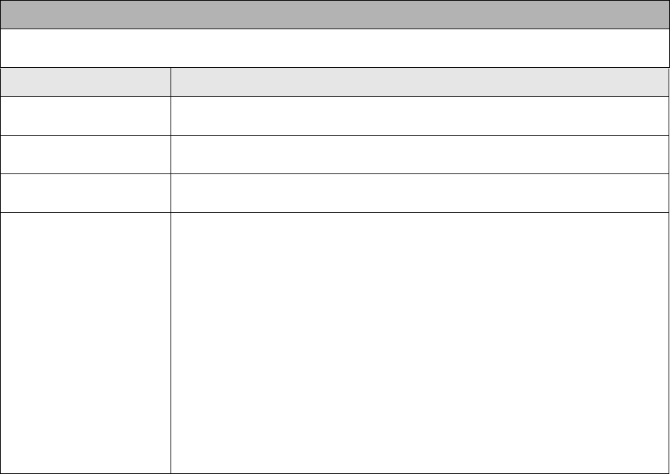
Section 5: Printer Configuration
M84Pro Service Manual PN 9001111A Page 5-17
SERVICE MODE
The Service Mode is entered from the Card Mode through the Advanced Mode. The Service Mode allows
the operator to set up the basic operation parameters of the printer.
LCD DISPLAY DEFINITION
V 05.00.03.00
INITIALIZING
Displays the firmware during the initialization.
ADVANCED MODE The Service Mode is entered from the Advanced Mode display by pressing the
right LINE key twice.
SERVICE MODE The Service Mode display indicates that the printer is in the Card Mode. To
advance to the first selection, press the FEED key.
GAP [X.XXV]
INPUT [X.XV]
The printer determines the location of the leading edge of the label by
measuring the difference between light levels when it sees either a label edge
or a black “EYE” mark. This adjustment allows the threshold voltage level to
be manually set between the maximum and minimum light levels. DIP switch
DSW2-2 selects the sensor type. If DSW2-2 is in the OFF position, the setting
will be for a See-Thru (or Gap) sensor and the LCD will display “GAP” on the
top line along with the current setting. If DSW2-2 is in the ON position, the
LCD will display “EYE” on the top line with its current setting. If the value
entered for the bottom line setting is “0.0V”, then the printer will automatically
calculate the setting when the first label is fed after the printer is powered on
or the head is closed. There are some instances where the automatically
calculated value must be adjusted to ensure reliable label feeding, such as
when the backing opacity or the reflectance of the EYE mark varies
significantly within a roll of labels or between label rolls. In these instances the
value should be set using the following procedures.

Section 5: Printer Configuration
M84Pro Service Manual PN: 9001111A Page 5-18
GAP [X.XXV]
INPUT [X.XV]
GAP - When setting the “gap” threshold, the voltage shown on the top line of
the display must be measured with nothing but the backing in the sensor and
then again with a label still attached to the backing. The formula to be used for
setting the threshold is:
(High Voltage Level + Low Voltage Level) x 0.5 = Start Value
1. Insert a label still attached to the backing into the sensor and close the
Label Hold-Down. Record the voltage shown on the top line of the LCD
panel. This line should have the message “GAP” on the top line (DIP
switch DSW2-2 = OFF). Ensure the label is fully under the sensor.
2. Strip the label from the backing and insert the backing strip under the
sensor and close the Label Lid. Record the voltage shown on the top line
of the LCD panel. The voltage ranges measured should be within the
following ranges:
Backing with label = 2.0V to 3.5V
Backing without label = Less than 1.0V
If the measured values are outside this range, it may be difficult finding a value
that will work properly under all conditions. If this is the case, a higher quality
label may be needed to get adequate performance.
3. Calculate the starting point voltage using the formula.
4. Use the LINE and FEED keys to step the counter to the desired setting.
The reading will advance to a setting of 4.9 (the maximum voltage). If a
value of “0.0” is set, the printer will automatically set the level each time
the printer is powered on with labels loaded and the head is closed.
5. Once the setting is correct, pressing the ENTER key will accept the
setting and advance the next display.
LCD DISPLAY DEFINITION

Section 5: Printer Configuration
M84Pro Service Manual PN 9001111A Page 5-19
EYE [X.XXV]
INPUT [X.XV]
EYE - When setting the “eye” threshold, the voltage must be measured with
nothing but the label under the sensor and then again with the printed “eye”
mark under the sensor. The formula for this is:
(High Voltage Level + Low Voltage Level) x 0.5 = Start Value
1. Insert a label into the sensor and close the label holder. Make sure the
printed “eye” mark is not under the sensor. Record the voltage shown on
the top line of the LCD panel. This line should have the message “EYE”
on the top line (DIP switch DSW2-2 = ON).
2. Pull the label forward until the “eye” mark is positioned under the sensor
(the voltage reading should be at its highest point). Record the voltage
shown on the top line of the LCD panel. The voltage ranges measured
should be within the following ranges:
Eye-Mark = 2.5V to 3.5V
Label Only = Less than 1.0V
If the measured values are outside this range, it may be difficult finding a value
that will work properly under all conditions. If this is the case, a higher quality
label may be needed to get adequate performance.
3. Calculate the starting point voltage using the formula.
4. Use the LINE and FEED keys to step the counter to the desired setting.
The reading will advance to a setting of 4.9 (the maximum voltage). If a
value of “0.0” is set, the printer will automatically set the level each time
the printer is powered on with labels loaded or the head is closed.
5. Once the setting is correct, pressing the ENTER key will accept the
setting and advance to the next display.
AUTO ONLINE FEED
YES NO
This selection specifies whether or not the printer will feed a label when it is
placed in the On-Line mode.
1. Use the LINE key to step the cursor to desired option. If Yes is selected,
the printer will feed a blank label anytime it enters the Online mode.
2. Press the FEED key to select the option and advance to the next display.
FEED ON ERROR
YES NO
This selection specifies whether or not the printer will feed a label when an
error condition is cleared.
1. Use the LINE key to step the cursor to desired option. If Yes is selected,
the printer will feed a blank label anytime an error condition is cleared.
2. Press the FEED key to select the option and advance to the next display.
REPRINT W/FEED
YES NO
Specifies whether or not the printer will print the last printed label stored in
memory when the FEED key is pressed in the Normal Online mode.
1. Use the LINE key to step the cursor to desired option. If Yes is selected,
the printer will reprint the last label when the FEED key is pressed. If the
printer is off-line, pressing the FEED key will feed a blank label.
2. Press the FEED key to select the option and advance to the next display
FORWARD/BACKFEED
DISTANCE DEFAULT
This display will only appear if Backfeed is enabled (DSW3-4 = OFF). The
maximum backfeed distance is 255 mm.
1. Use the LINE key to select either the Default or the Manual option.
2. Press the FEED key to select the option and advance to the next display
LCD DISPLAY DEFINITION

Section 5: Printer Configuration
M84Pro Service Manual PN: 9001111A Page 5-20
FORWARD/BACKFEED
DISTANCE XXXmm
3. If Manual option is selected, use the Cursor keys to advance the distance
to the desired setting. Each time the CURSOR key is pressed, the
distance will advance 1 mm. The maximum distance is 255 mm.
4. Press the FEED key to select the option and advance to the next display
EXT PIN 9 SELECT
MODE1 MODE2
Allows selection of the conditions that cause the signal on Pin 9 of the EXT
connector to be true. If Mode1 is selected, pin 9 will be true when the printer is
ready to print, i.e. it is on-line and has a print job loaded (a quantity of labels to
be printed on the display). If Mode 2 is selected, pin 9 will be true if the printer
is on-line.
1. Use the LINE key to step the cursor to the desired option.
2. Press the FEED key to select the option and advance to the next display
EURO CODE
D5
Allows the dexadecimal code to be specified for the character replaced with
the Euro Character. The default is D5H.
1. Use the LINE key to step to the desired option of the first character.
2. Press the FEED key to select the option and advance the cursor to the
second character of the desired hexadecimal code.
3. Repeat steps 1 and 2 for each character.
4. Press the FEED key to select the option and advance to the next display
SELECT LANGUAGE
ENGLISH
Allows the selection of the character set used by the printer. The options are
English, French, German, Spanish, Italian and Portuguese.
1. Use the LINE key to advance to the desired language option.
2. Press the FEED key to select the option and advance to the next display
IGNORE CAN/DLE
YES NO
If the printer is placed in the Multi-Item Buffer Mode (DSW2-5 = ON), the user
can choose to ignore CAN (18H) and DLE (10H) commands used in bi-
directional communications (refer to section: Interface Specifications). If the
Single Item Buffer Mode is chosen (DSW2-5 = OFF), this display will be
skipped.
PRIORITY SETTING
COMMAND LCD
Allows the assignment of a priority for Print Darkness, Print Speed, and Print
Offset setting methods. If LCD is selected, the setting established via the LCD
display/menu system will be used for an incoming label job, regardless of any
different command settings. If Command is selected, any commands in the
label job will take precedence and be used for printing the job.
1. Use the LINE key to step to the desired priority option.
2. Press the FEED key to select the option and advance to the next display
LABEL RE-DETECT
ENABLE DISABLE
Allows disabling the feeding of a blank label upon power up. If Enable is
selected, the printer will automatically feed a label until it detects a label
image. This will correctly position the next printed label under the print head. If
Disable is selected, the printer will not attempt detection and the operator is
responsible for ensuring a correctly positioned label before printing.
1. Use the LINE key to step to the desired option.
2. Press the FEED key to select the option and advance to the next display
LCD DISPLAY DEFINITION
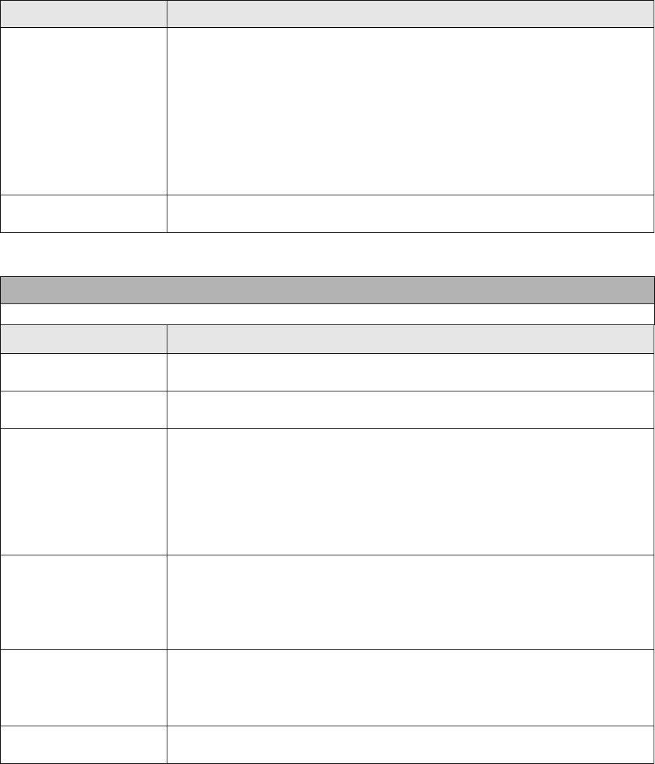
Section 5: Printer Configuration
M84Pro Service Manual PN 9001111A Page 5-21
IEEE1284
ACK SIGNAL 00.5
If the printer is placed in the Single Item Buffer Mode (DSW2-5 = ON), this
selection allows the width of the IEEE1284 ACK pulse to be set. In the Multi-
Item Buffer Mode, this display will be skipped.The range is 0.5 µsec to 10
µsec.
1. Use the LINE key to step the display to the desired option. The setting will
advance in increments of 0.1 µsec each time the CURSOR key is pressed
until the setting reaches 10.0 µsec when it will wrap around to the 0.5
µsec setting.
2. Press the FEED key to select the option and advance to the next display
SERVICE MODE The Service mode is exited by powering the printer off and then back on.
COUNTERS MODE
The Counters Mode is provided to allow the user to access the internal printer cousters.
LCD DISPLAY DEFINITION
ADVANCED MODE The Counter Mode is accessed from the Advanced Mode. Press the
CURSOR keys to step to the Counter Mode.
COUNTERS MODE Press the FEED key to advance the display to the counter selections.
COUNTERS
HD CUT LIFE
The counters are identified in the display as:
HD: Head Counter (should be reset when print head is replaced)
CUT: Cutter Counter
LIFE: Life Counter (cannot be reset)
1. Use the LINE key to step the cursor to the desired counter; Head (HD)
counter or the LIFE counter. The default position is the Head Counter.
HEAD COUNTER
0.5M
2. Press the FEED key to select the desired option. The current value (in
meters) stored in the counter will be displayed. The maximum number of
digits displayed is 8.
3. Press the FEED key again to advance the counter to the Clear mode. All
counters with the exception of the LIFE counter will be cleared.
HEAD COUNT CLEAR
YES NO
4. Use the LINE key to select the desired option. If wanting to read the
counter value only, select NO. If wanting to read the counter and reset it to
0.0, select YES.
5. Press the FEED key to return to the Counters Mode display.
COUNTERS MODE 6. To exit the Counters Mode, turn power to the printer off and then back on.
LCD DISPLAY DEFINITION
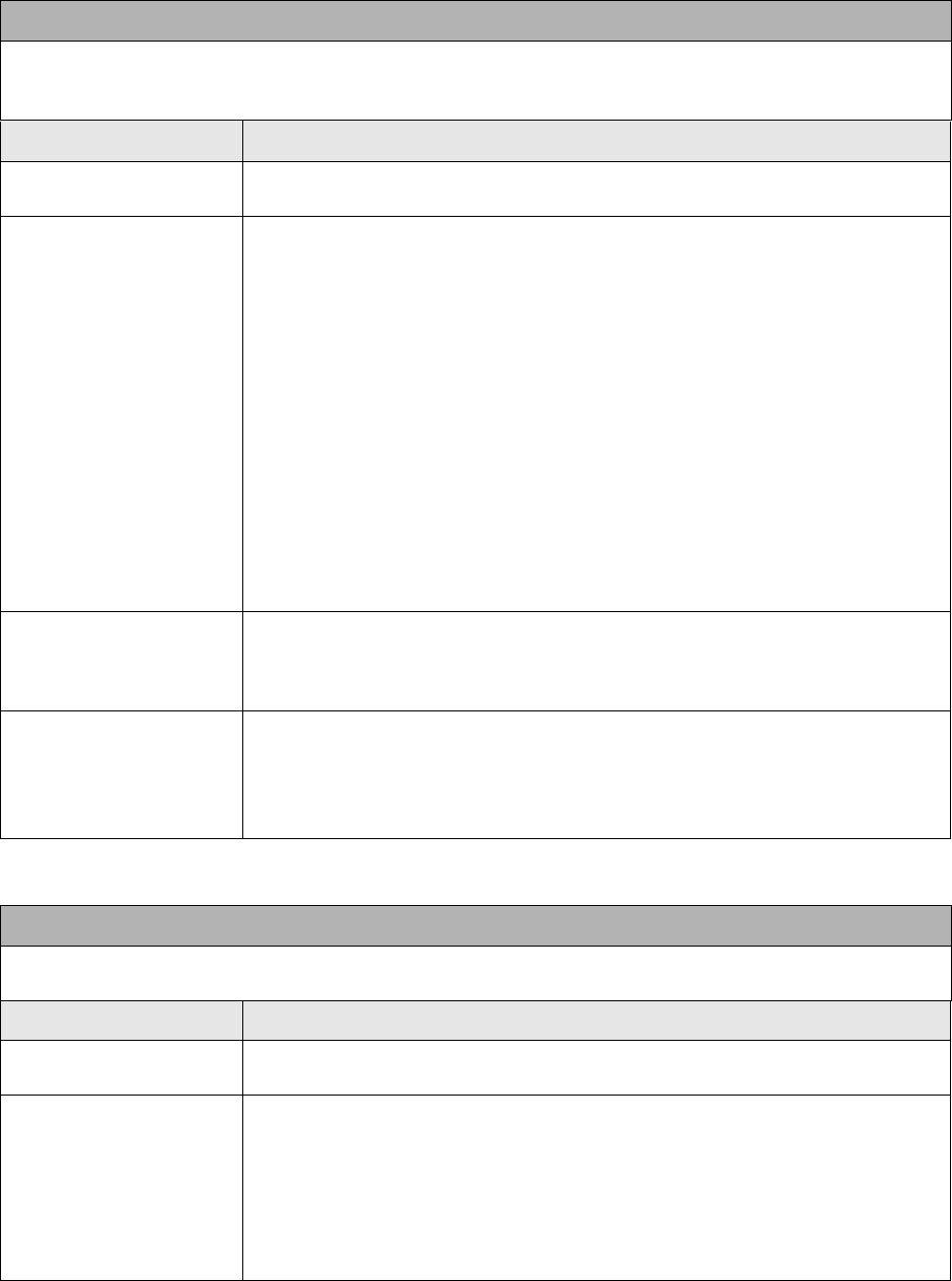
Section 5: Printer Configuration
M84Pro Service Manual PN: 9001111A Page 5-22
.
TEST PRINT MODE
The Test Print Mode offers 4 different status labels for troubleshooting. If DSW3-5 is in the OFF position,
the Test Print cycle must be initiated with a Print Start signal on the EXT connector You enter the Test
Print Mode by pressing the FEED key while powering the printer on.
LCD DISPLAY DEFINITION
V 05.00.03.00
INITIALIZING
Displays the firmware during the initialization.
TEST PRINT MODE
CONFIGURATION
This option allows printing of a test label. It is recommended that a test label
be printed after the settings in the Advanced Mode have been changed. The
test label provides verification that the correct changes were entered.
1. Press the FEED key while switching on the power switch to access the
Test Print Mode.
2. Release the FEED key when the printer beeps.
3. Use the CURSOR keys to step the cursor to the test label type option
desired. They are:
CONFIGURATION
BARCODE
HEADCHECK
MEMORY
FACTORY
4. Press the FEED key to select the desired option.
TEST PRINT SIZE
10 CM
Note: This screen will not be displayed for the Memory Test Label.
This display allows label width selection.
1. Use the LINE key to step to the desired label width option.
PRESS FEED KEY TO
STOP PRINTING
2. Press the FEED key to select the option.
3. Press the FEED key to start printing test labels continuously.
4. Press the FEED key to stop the printer.
5. To exit the Test Print Mode, power the printer off and then back on.
DEFAULT SETTINGS MODE
Occassionally it is desirable to reset all printer configuration settings to their original default conditions.
This allows the operator to start reconfiguration of the printer starting from a know set of conditions.
LCD DISPLAY DEFINITION
V 05.00.03.00
INITIALIZING
Displays the firmware during the initialization.
DEFAULT SETTING
YES NO
Allows the reset of original printer default settings. Enter the Default Setting
Mode by:
1. Press and hold the LINE and FEED keys while switching on power.
1. Release the LINE and FEED key when the printer emits one long beep.
1. Use the LINE key to step to either the YES or NO option.
2. Press the FEED key to select the desired option.
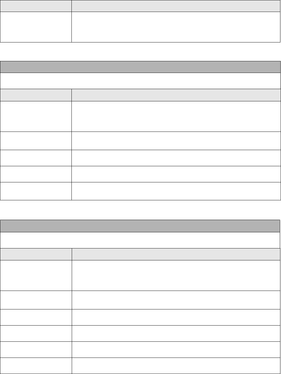
Section 5: Printer Configuration
M84Pro Service Manual PN 9001111A Page 5-23
DEFAULT SETTING
COMPLETED
When the printer has completed the reset process it will beep 3 times and the
Default Setting Completed display will appear. At this time the printer is in the
default configuration.To exit the Default Setting Mode, power the printer off
and then back on.
MAINTENANCE/FACTORY MODE
This function is used to clear counters and reset the printer’s firmware. It is also used after upgrading the
flash firmware or installing a new memory module.
LCD DISPLAY DEFINITION
MAINTENANCE MODE
DIPSW2-4 ON>OFF
Record all dip switch positions and place all in the OFF position.
1. Place DSW2-4 switch in the ON position.
2. Press and hold the LINE and FEED keys while switching on the power.
3. Release the LINE and FEED keys when the printer beeps.
FACTORY MODE 4. Place the DSW2-4 switch in the OFF position.
5. Press the FEED key to advance to the next display.
COUNTER CLEAR
NONE
6. Use the LINE key to step the cursor to the desired option.
7. Press the FEED key to select the option and advance to the next display.
PRINT SIZE
SMALL LARGE
8. Use the LINE key to step to the desired option (128 mm or 266 mm).
9. Press the FEED key to select the option and initiate test printing.
PRESS ENTER KEY
TO STOP PRINTING
The FEED key may be pressed and repressed to start and stop printing
at will.
ALL CLEAR MODE
This function is used to clear counters and reset the printer’s firmware. It is also used after upgrading the
flash firmware or installing a new memory module.
LCD DISPLAY DEFINITION
MAINTENANCE MODE
DIPSW2-4 ON>OFF
Record all dip switch positions and place all in the OFF position.
1. Place DSW2-4 switch in the ON position.
2. Press and hold the LINE and FEED keys while switching on the power.
3. Release the LINE and FEED keys when the printer beeps.
FACTORY MODE 4. Place the DSW2-4 switch in the OFF position.
5. Press the FEED key to advance to the next display.
ALL CLEAR MODE 6. Press the FEED key to ENTER THE ALL CLEAR COUNTER EEPROM
Mode.
ALL CLEAR
COUNTER EEPROM
7. Use the LINE key to step to the desired option (COUNTER).
8. Press the FEED key to select the option and display the current value.
XXXXXXXALL CLEAR
YES NO
9. Use the LINE key to step to the desired option (YES) and ENTER to
select the option.
XXXXXXXALL CLEAR
COMPLETED
LCD DISPLAY DEFINITION
Section 5: Printer Configuration
M84Pro Service Manual PN: 9001111A Page 5-24
CLEAR NON-STANDARD PROTOCOL
The standard protocol codes used by the printer can be modified to accomodate the requirements of
different host systems. However, if the printer is to be used with a system that does not use the custom
protocol codes, they can be cleared and the default protocol codes reactivated. The default values are:
STX = 7BH, ETX = 7DH, ESC = 5EH, ENQ = 40H, NULL = 7EH, CAN = 21H and OFFLINE = 5DH.
LCD DISPLAY DEFINITION
V 05.00.03.00
INITIALIZING
Displays the firmware during the initialization.
ALT.PROTOCOL
DEFAULT COMPLETE
To Clear Non-Standard protocol codes:
1. Place DSW2-7 in the On position.
2. Press and hold the LINE and FEED keys while switching on the printer.
3. Release the LINE and FEED keys when the printer emits one long beep.
4. Standby for the printer to replace the Alternate protocol codes with the
default values.
The printer will emit two short beeps when the process is complete. To exit the
mode, power the printer off and then back on.
DOWNLOAD USER DEFINED PROTOCOL CODES
The user can define a set of custom protocol codes and download them to the printer using the <ESC>LD
command.
LCD DISPLAY DEFINITION
V 05.00.03.00
INITIALIZING
Displays the firmware during the initialization.
USER DOWNLOAD
PRESS THE LINE KEY
Allows the replacement of the Standard Protocol Codes or the Alternate set of
Protocol Codes. To enter the User Download mode:
1. Place DSW2-7 in the on position.
2. Press and hold the LINE and FEED keys while switching on the power.
3. Release the LINE and FEED keys when the printer emits one long beep.
USER DOWNLOAD
WAITING
4. Press the LINE key. The printer is now waiting for the data to be sent.
5. Transmit the download data command stream to the printer.
After the data has been received, the printer will beep and print a status label.
If it does not beep and print a status label, the printer did not accept the data.
If the printer did not beep and print a status label, turn the printer off and check
your data stream for errors and start the download process over.
If the custom codes are correct, press the FEED key to accept them and
terminate the download process. If they are incorrect, turn the printer off
without pressing the ENTER key and begin the process again.

Section 5: Printer Configuration
M84Pro Service Manual PN 9001111A Page 5-25
HEX DUMP MODE
In addition to the Test Print Labels, the printer can print the contents of the receive buffer in a hexadecimal
format to allow the data stream to be examined for errors and troubleshooting.
LCD DISPLAY DEFINITION
V 05.00.03.00
INITIALIZING
Displays the firmware during the initialization.
ONLINE
QTY:000000
The Hex Dump Mode is entered by placing DSW2-4 in the On position and
powering the printer on.
1. The printer is now ready to receive data.
2. Send the data stream to the printer.
3. The received data will be printed in a hexadecimal format4.
4. To return the printer to normal operation, place DSW2-4 in the off position
and power the printer off and then back on.

M84Pro Service Manual PN: 9001111A Page 6-1
6
TROUBLESHOOTING
ERROR SIGNALS
The LED display, Front Panel LED Indicators and Buzzer provide a visual and audio indication of
the type of error encountered. Find the correct symptom in the table below to reference the
correct response.
LED LCD MESSAGE BEEP ERROR CONDITION TO CLEAR
Error on Machine error 1 long Machine Error Cycle power on/off.
Error on EEPROM error 1 long EEPROM read/write error Cycle power on/off.
Error on Head error 1 long Print Head is damaged Replace print head.
Cycle power.
Error on Sensor error 3 short Sensor Cycle power on/off.
Error blinks Card r/w error 1 long Memory card read/write Format card and cycle
power.
Error blinks Card low Battery 1 long Memory card battery low Replace battery and
cycle power.
Error blinks Head Open 3 short Head open Latch print head.
Error on Line
blinks
Parity Error 3 short RS232 parity error Match parity to system.
Error on Line
blinks
Overrun Error 3 short RS232 overrun error Verify RS232 settings.
Error on Line
blinks
Framing Error 3 short RS232 framing error Verify RS232 settings
Error on Line
blinks
Buffer Over 3 short Buffer overflow Verify RS232 settings.
Error on Line
blinks
Paper End 3 short Media end or misselected
media type.
Replenish media, select
correct media, open/
close head lever, open/
close media hold down
Error blinks
Ribbon on
Ribbon End 3 short Ribbon end or ribbon broken. Replace ribbon. Open/
Close Head Lever.
Open/Close Media Hold
Down
Error blinks,
Label blinks
Media Error 3 short Media error Open/Close head lever.
Ribbon blinks None Ribbon near end. Replace ribbon with full
roll.
Line blinks None Buffer near full Slow down transmission
rate.

Section 6: Troubleshooting
M84Pro Service Manual PN 9001111A Page 6-2
TROUBLESHOOTING TABLE
Use the tables below to isolate problems based on their symptoms. Refer to their relative
procedures as applicable to correct the problem. The troubleshooting table below includes the
following general symptom descriptions:
Image Voids No Ribbon Movement Power LED Not Illuminated
Ribbon Wrinkle No Label Movement Error LED Illuminated
Light Print Images No Printed Image On Line Led not Illuminated
Smeared Print Images Display Problem No Label Drive
IMAGE VOIDS
Poor label quality. Use thermal transfer compatible stock.
Poor ribbon quality. Use genuine SATO ribbons.
Ribbon not matched to label stock. Consult with media supplier.
Damaged electronics. Replace circuit board.
Damaged platen. Replace platen.
RIBBON WRINKLING
Poor head alignment. Adjust head balance, ribbon roller, and head alignment.
Poor ribbon tension. Adjust tension as required.
Worn platen. Replace as necessary.
Foreign material on head or platen. Clean as required.
Foreign material no labels. Use high quality label stock.
Damaged print head. Replace print head as required.
LIGHT PRINT IMAGES
Poor label quality. Use thermal transfer compatible stock.
Poor quality ribbons. Use genuine SATO ribbons.
Low print head energy/darkness. Adjust darkness control. Refer to Operators Manual.
Low print head pressure. Adjust head balance.
Ribbon not matched to label stock. Use Premier II ribbon with a “1C” thermal transfer ribbon stock
or equivalent for optimum results.
Low ribbon and drive torque or no ribbon
movement.
Adjust ribbon drive clutch.
Foreign material on print head. Clean print head and platen roller.
Poor head alignment. Align print head as required.
Excessive print speed. Reduce print speed setting.
Section 6: Troubleshooting
M84Pro Service Manual PN: 9001111A Page 6-3
SMEARED PRINT IMAGES
Poor label quality. Use high quality label stock.
Poor ribbon quality. Use genuine SATO ribbons.
Foreign material on print head and platen
roller.
Clean print head and platen roller.
Foreign material on labels. Use high quality label stock.
Excessive print head energy. Adjust darkness control.
Excessive print speed. Adjust as speed as required.
Excessive head pressure or incorrect
carbon tension.
Adjust head balance.
NO RIBBON MOVEMENT
Incorrect ribbon core size. Use genuine SATO ribbons.
Loose drive clutch. Adjust drive clutch tension.
Loose platen drive belt. Adjust or replace drive belt as necessary.
No +24 volt output. Test power supply and replace as necessary.
Damaged electronics. Replace circuit board.
NO LABEL MOVEMENT
Loose or broken platen drive belt. Adjust or replace platen drive belt as required.
Incorrect label pitch sensor selected. Select the correct label sensor type (DSW2-2).
No +24 volt output. Replace fuse on main circuit board. Test power supply and
replace as required.
Loose set screw on platen pulley/stepper
motor.
Tighten set screws.
NO PRINTED IMAGE
Print head is disconnected. Ensure that print head wiring harness is connected on each
end.
Ribbon is installed upside down. Ensure a correct ribbon installation.
No +24 volt output. Test power supply and replace as necessary.
Damaged print head. Replace print head.
Damaged electronics. Replace circuit board.
LED FIELD ILLUMINATED BUT WITHOUT WORDS OR NO DISPLAY AT ALL
Ribbon sensor cable disconnected. Ensure a proper connection.
Incorrectly positioned display potentiom-
eter.
Adjust as required.
POWER LED NOT ILLUMINATED
AC power cable disconnected. Ensure the cable is connected at each end.
Section 6: Troubleshooting
M84Pro Service Manual PN 9001111A Page 6-4
TROUBLESHOOTING PROCEDURES
The procedures below provide in depth instructions on symptom analysis of specific
components. If it is suspected that the problem lies within one of these components, refer to the
relative instructions.
RS232 SERIAL INTERFACE
• Ensure the serial cable is thoroughly connected to the PC and the printer.
• Ensure the serial cable is not defective. The minimum requirements is that a Null Modem
Cable or correct Pin Outs be used and that it be manufactured to specifications. Refer to the
Interface Specifications section of this manual.
• Ensure the RS232 Interface Module is installed. Different module types will have an impact
on transmission speed.
• Ensure the data stream is correct, all letters of command codes are in upper case, and with-
out spaces. Carriage Returns are also not acceptable in line fields.
Main power fuse defective. Replace fuse.
Defective power supply. Test with meter and replace as required.
ERROR LED ILLUMINATED
Print head not latched into position. Ensure print head assembly is latched.
LABEL LED IS ILLUMINATED
Label supply roll is empty. Replenish label supply.
Label stock is not routed through sensor. Ensure label roll is correctly installed.
Label sensor incorrectly positioned. Adjust sensor position.
Label sensor is blocked. Clean label sensor.
Incorrect label sensor threshold setting. Adjust label sensor threshold.
Platen drive malfunction. Perform drive train analysis.
RIBBON LED ILLUMINATED
Ribbon supply roll is empty. Replenish ribbon supply.
Ribbon supply is misaligned. Realign ribbon sensor.
Ribbon sensor is blocked. Clean ribbon sensor.
Ribbon rewind is without core. Install cardboard core.
CAUTION: NEVER CONNECT OR DISCONNECT INTERFACE CABLES
(OR USE A SWITCH BOX) WITH POWER APPLIED TO EITHER THE
PRINTER OR THE HOST. THIS MAY CAUSE DAMAGE TO THE INTER-
FACE CIRCUITRY AND IS NOT COVERED BY WARRANTY.
POWER LED NOT ILLUMINATED

Section 6: Troubleshooting
M84Pro Service Manual PN: 9001111A Page 6-5
• Ensure the Baud rate, Parity, Data Bits, and Stop Bits are consistent with that of computer.
Print a Configuration Test Label to determine the RS232 settings.
• Ensure the printer is receiving from the computer using a Receive Buffer Hex Dump. Refer to
the Hex Dump procedure in this manual for instructions. The printer will print (only once) a
hexadecimal dump of everything it has received from the host computer. Each hexadecimal
character represents a character the printer received. Analyze and troubleshoot the data
stream.
While checking the hex dump printout, look for ODH OAH (carriage return and line feed) char-
acters throughout. The command string should be continuous. CR or LF characters are not
allowed between the start command (<ESC>A) and the stop command (<ESC>Z). If Basic is
being used, it may be adding these characters automatically as the line wraps. Adding a
width statement to your program can help suppress these extra ODH OAH characters by
expanding the line length up to 255 characters.
If not programming in BASIC, check to see if the equivalent statement in the language exists
to suppress extra carriage returns and line feeds from data being sent to the printer. The data
stream must be one complete line going to the printer.
UNIVERSAL SERIAL BUS (USB) INTERFACE
If nothing prints when during a test print, verify that the device drivers have been successively
installed by performing the following:
1. Click on Start, Settings, and then Control Panel.
2. Click on System within the new window.
3. Click on the Device Manager tab.
4. Ensure that the View Device By Type is checked.
5. Scroll down to SATO-USB Device and ensure that errors do not exist. Reinstall as required.
6. Reboot the PC and the printer.
7. Contact Microsoft technical support for further assistance as required.
PARALLEL INTERFACE
• Ensure the printer cable is thoroughly connected to the PC and the printer.
• Ensure the printer cable is connected to the correct ports on each end.
• Ensure the printer cable (IEEE1284) meets specifications. The computer may not be able to
communicate correctly otherwise.
• Ensure the Interface Module is installed.
NOTE: A small label may produce a large amount of data when printed in
Hex Dump.

Section 6: Troubleshooting
M84Pro Service Manual PN 9001111A Page 6-6
• Ensure the data stream is correct, all letters of command codes are in upper case, and with-
out spaces.
• Ensure protocol codes are set for standard or non-standard and that they are consistent with
the data stream.
• Ensure the printer is receiving from the computer using a Receive Buffer Hex Dump. Refer to
that procedure for instructions. The printer will print (only once) a hexadecimal dump of
everything it has received from the host computer. Each hexadecimal character represents a
character the printer received. Analyze and troubleshoot the data stream.
While checking the hex dump printout, look for ODH OAH (carriage return and line feed) char-
acters throughout. The command string should be continuous. CR or LF characters are not
allowed between the start command (<ESC>A) and the stop command (<ESC>Z). If Basic is
being used, it may be adding these characters automatically as the line wraps. Adding a
width statement to your program can help suppress these extra ODH OAH characters by
expanding the line length up to 255 characters.
If not programming in BASIC, check to see if the equivalent statement in language exists to
suppress extra carriage returns and line feeds from data being sent to the printer. The data
stream must be one complete line going to the printer.
LAN ETHERNET INTERFACE
•If the printer does not come up ready: Ensure the printer is powered on, all cables are con-
nected, and the printer is on-line. If possible, connect a terminal to the serial port and observe
for a boot prompt indicating the print server firmware has not been loaded properly. If reload-
ing does not correct the problem, try pressing switch 1 for more than 10 seconds. If the prob-
lem persists, the product may be defective.
•If the printer comes up ready but will not print: There is a problem with the interface
between the server and the printer, network connection or cabling, or a queue setup flaw. The
queue setup flaw could be the result of a faulty print server setup or other protocol-related
scenarios. Systematically perform checks and tests to isolate the cause.
The interface between the printer and server may be checked by waiting approximately two
minutes after the printer is powered on and then run a self-test label. If a self-test label does
not print, there could be a hardware problem. Double check the cable connections. In some
rare cases, disabling NBUF with the command SET PORT P1 NBUF DISABLED will solve
the problem.
If connecting to a 10baseT network, verify that the OK LED is illuminated. If the appropriate
LED’s are not on, there is a possibility of a defective cable or connector. Try connecting a
different cable, port, or device to observe the results.
If using a repeater or hub, ensure that SQE is turned off at the hub (this is the default setting
for most hubs). Also, test the hub or repeater by trying the print server on a different port.
NOTE: A small label may produce a large amount of data when printed in
Hex Dump.
Section 6: Troubleshooting
M84Pro Service Manual PN: 9001111A Page 6-7
If using a bridge or router located between the print server and the host computer, ensure
that the device is setup to allow the print server to send and receive data from the host. For
example, a bridge can only be set up allow certain types of Ethernet addresses to pass
through (a process known as filtering). Such a bridge must be configured to allow print server
addresses. Likewise, a router can be set up to only pass certain protocols. Ensure that the
desired protocol can be passed through to the print server. In the case of routers, also ensure
that the protocol is routable (LAT, NetBEUI, and DLC/LLC are not routable.
Ensure that you are not attempting to perform an illegal operation such as printing a label l
larger than the printer can handle.
Check the protocol troubleshooting sections provided with the Ethernet Interface Module for
additional causes of intermittent printer problems.
• Experiencing intermittent printing problems: Excessive NetWare polling may be a big cause
of intermittent problems. Ensure that only the needed NetWare file servers have been
enabled (do a SHOW NETWARE command from the print server console to see the enabled
file servers). If V3.21 or earlier versions of firmware is in use, ensure that NetWare polling is
disabled by using the console command SET NETWARE RANGE 0. If Netware is not in use,
disable NEtWare entirely with the command SET NETWARE DISABLED.
Check the individual troubleshooting sections provided with the Ethernet Plug-In Interface
Module for additional causes of intermittent printer problems.
TP TEST MODULE USAGE
The SATO TP Test Module is a purchase option specially designed and sold by SATO America
to assist in troubleshooting SATO Printers. The use of this device will facilitate the identification
and isolation of problem circuitry and for voltage adjustment.
1 Remove applicable housing covers as directed in Figure 10-1 of the Diagrams section.
2 Connect the harness from Test Module (1, FIgure 6-1) to main circuit board connector (2).
3 Connect the multimeter ground probe to the pin identified as GND (3) on Test Module (1).
4 Connect the multimeter positive probe to the pin identified as SIG (4) on Test Module (1).
5 Turn on the printer and rotate Test Module dial (5) to the required position.
6 Record the multimeter values and confirm they are within specified tolerences.
NOTE: The ground and positive probes of the multimeter may also be con-
nected to the Test Module by inserting the probes into their respective con-
nection ports (6) arranged vertically along the right front side of the Test
Module. If this method is used, the dial should be set at (0) zero. Refer to Fig-
ure 6-2 for connection port identification.
NOTE: Refer to Figure 6-2 for the correct Test Module position.
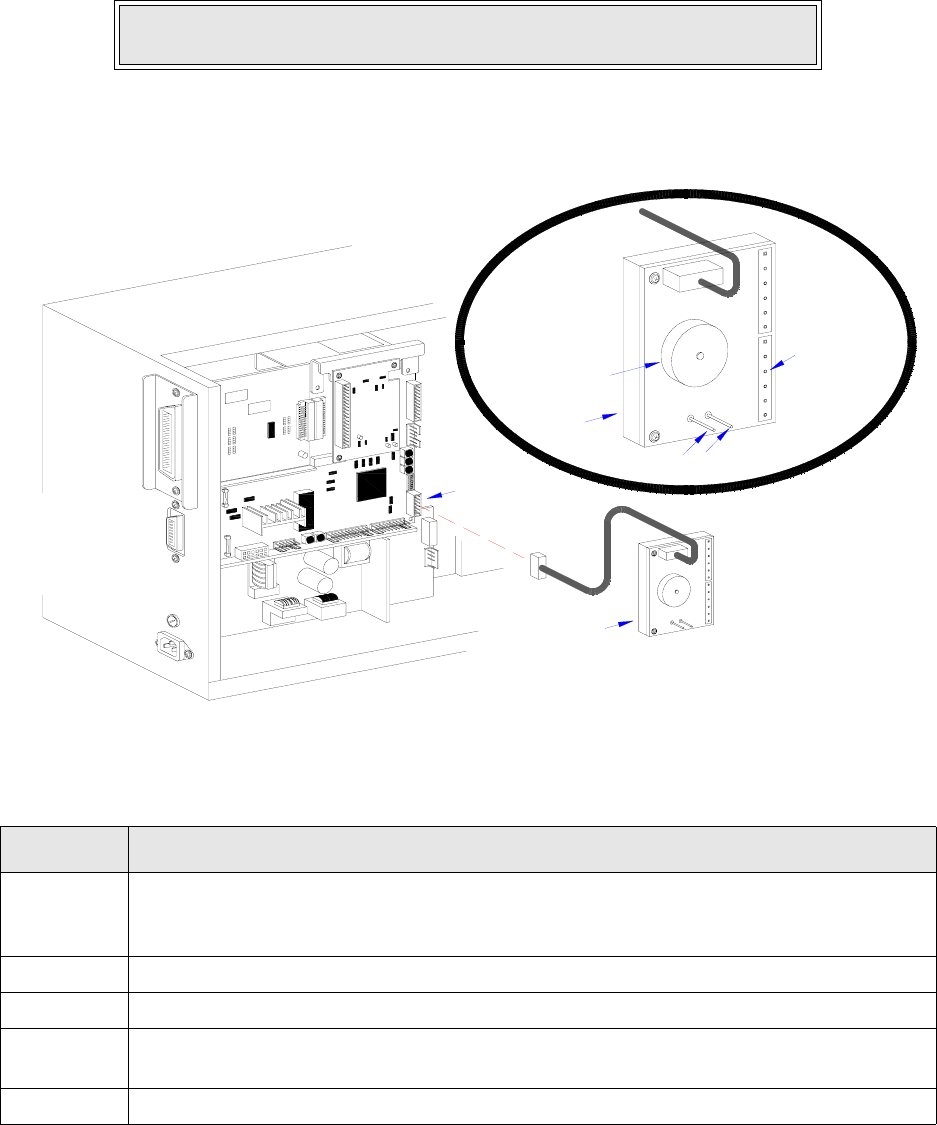
Section 6: Troubleshooting
M84Pro Service Manual PN 9001111A Page 6-8
7 Troubleshoot and/or replace components as directed in their respective procedures.
Figure 6-1, TP Test Module Usage
NOTE: Voltage readings must be +/- 10% of specification for proper
operation.
DIAL APPLICATION DESCRIPTION
0 through 3 Used to determine voltage. Refer to the specifications section of this manual to determine
a component’s required voltage level. Set the dial to that voltage requirement and the milli-
meter reading should be in the same range if properly performing.
4 Used for testing and adjustment of the VR5 potentiometer when Eye-Mark printing.
5 Used for testing and adjustment of the VR4 potentiometer when GAP printing.
6 Used for testing and adjustment of the VR2 potentiometer when printing with dispencer.
The potentiometer should be turned fully clock-wise for this operation.
7 Used for testing and adjustment of the VR3 potentiometer for ribbon end sensing.
IEEE1284 + RS BOARD
01
2
8
7
6
54
3
GNDSIG
1A
2A
3A
4A
6B
5B
4B
3B
1B
2B
6A
5A
2
6
5A
6A
2B
1B
3B
4B
5B
6B
4A
3A
2A
1A
SIG
GND
3
4
5
6
7
8
2
1
0
1
1
5
34
Section 6: Troubleshooting
M84Pro Service Manual PN: 9001111A Page 6-9
RIBBON SENSOR OPERATION VERIFICATION
Verification that the ribbon sensor is operational may be achieved using the Operator Panel
located on the front housing cover.
1 Access the dip switches located on the Operator Panel.
2 Record all dip switch positions.
3 Place DSW2-1 dip switch in the off position, then switch off the printer.
4 Remove ribbon from the printer as applicable and latch down print head.
5 Switch on the printer.
6 Press the LINE key to place the printer off-line.
7 Press the FEED key and wait for the printer to beep.
8 Switch off the printer, install ribbon, and switch the printer on again.
9 Press the LINE key to place the printer off-line.
10 Press the FEED key to generate a blank label and confirm that the ribbon has been properly
installed.
LCD DISPLAY: INITIALIZING
ROM V00.00.00.00
LCD DISPLAY: ONLINE
QTY:000000
LCD DISPLAY: RIBBON END
NOTE: The ribbon end display is confirmation that the sensor is functioning.
LCD DISPLAY: INITIALIZING
ROM V00.00.00.00
Section 6: Troubleshooting
M84Pro Service Manual PN 9001111A Page 6-10
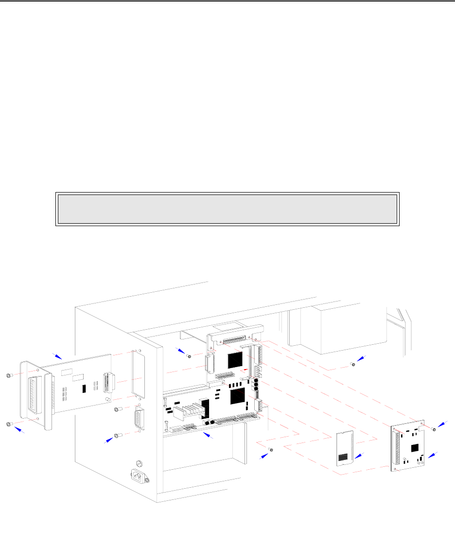
M84Pro Service Manual PN: 9001111A Page 7-1
7
REPLACEMENT PROCEDURES
The M84PRO Printer contains replaceable components and sub-assemblies. This section
contains step-by-step instructions for the removal and replacement of those primary components
and sub-assemblies that are subject to wear or damage.
MAIN CIRCUIT BOARD REPLACEMENT
The main circuit board contains the control electronics for the printer and is located behind the
left side cover. The interface board must be removed prior to the main circuit board. The
daughter board and optional memory card should also be removed to prevent possible damage
during circuit board removal.
1 Switch off the printer and disconnect the power supply cord.
2 Open/remove applicable housing covers.
3 Disconnect all wiring harnesses attached to main circuit board (1, Figure 7-1) or daughter
board (2).
Figure 7-1, Circuit Board Replacement
NOTE: Figure 10-1 of the Daigrams & Schematics section provides guidance
on housing cover removal.
IEEE1284 + RS BOARD
BELT CONFIGURATION
1
2
3
4
5
6
7
8
8
8
POWER BOARD
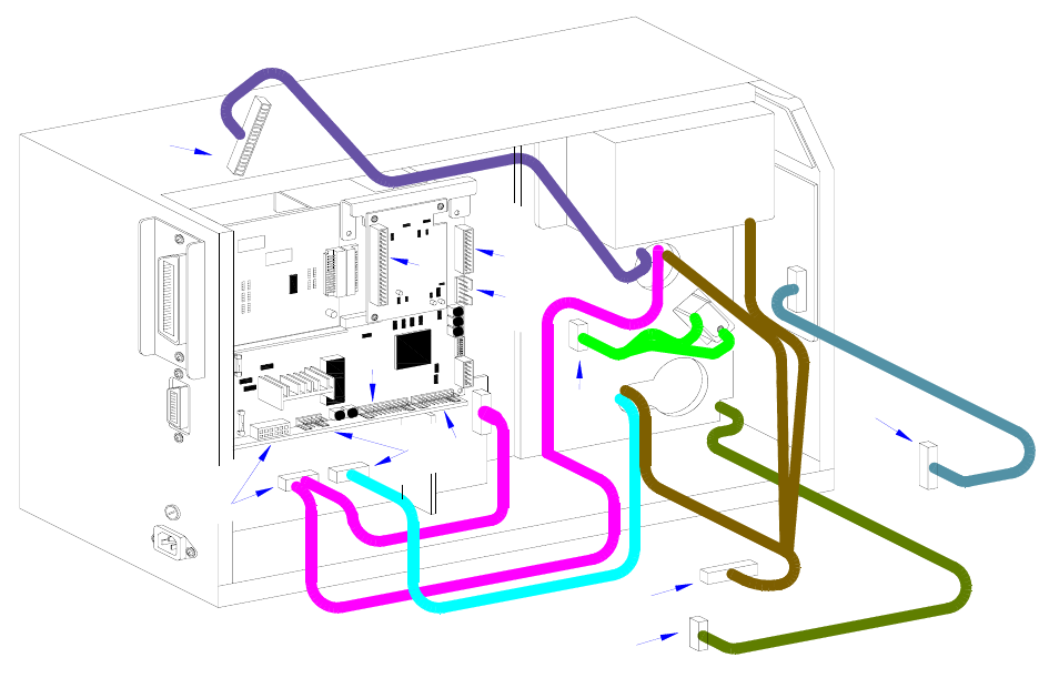
Section 7: Replacement Procedures
M84Pro Service Manual PN 9001111A Page 7-2
4 Remove two screws (3) securing interface board (4) to printer housing.
5 Withdraw interface board (4) from its connection with main circuit board (1).
6 Remove three screws (5) securing daughter board (2) to main circuit board (1).
7 Withdraw daughter board (2) from its connection with main circuit board (1).
8 Detach optional memory card (6) from its connection with main circuit board (1).
9 Remove two exterior screws (7) securing main circuit board (1) to the housing.
10 Remove three interior screws (8) securing main circuit board (1) to the printer frame.
11 Withdraw main circuit board (1) from within the printer.
12 Prepare to replace main circuit board (1).
13 Install main circuit board (1) into mounting position and secure to the printer frame using
three screws (8).
14 Secure the exterior of main circuit board (1) using two screws (7).
15 Connect optional memory card (6) to main circuit board (1) as applicable.
16 Connect and attach daughter board (2) to main circuit board (1) using three screws (5).
17 Connect interface board (4) to main circuit board (1) and secure to housing using two
screws (3).
18 Reconnect all wiring harnesses (Figure 7-2).
19 Reconnect power supply cord, test cycle, and reattach housing covers.
Figure 7-2, Circuit Board Replacement
IEEE1284 + RS BOARD
C
A
B
D
G
F
E
F
E
D
C
G
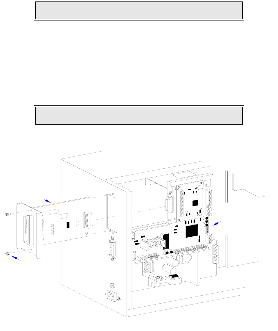
Section 7: Replacement Procedures
M84Pro Service Manual PN: 9001111A Page 7-3
INTERFACE BOARD REPLACEMENT
1 Switch off the printer and disconnect the power supply cord.
2 Open/remove the top, right, and left housing covers.
3 Remove two screws (1, Figure 7-3) securing interface board (2) on the exterior back side of
printer.
4 Carefully withdraw interface board (2) from its connection with main circuit board (3).
5 Insert replacement interface board (2) through the housing slot to connect with main circuit
board (3).
6 Secure interface board (2) to printer housing using two screws (1).
7 Reconnect power supply cord, test cycle, and reattach left side cover.
Figure 7-3, Interface Board Replacement
NOTE: Figure 10-1 of the Daigrams & Schematics section provides guidance
on housing cover removal.
NOTE: Figure 10-1 of the Daigrams & Schematics section provides guidance
on housing cover installation.
IEEE1284 + RS BOARD
2
1
3
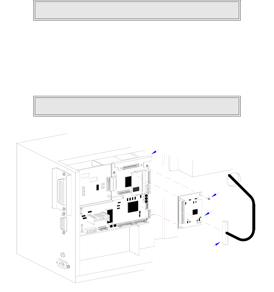
Section 7: Replacement Procedures
M84Pro Service Manual PN 9001111A Page 7-4
DAUGHTER BOARD REPLACEMENT
1 Switch off the printer and disconnect the power supply cord.
2 Open/remove thetop, right, and left housing covers.
3 Disconnect the print head wiring harness (1, Figure 7-4) from daughter board (2).
4 Remove the three screws (3) securing daughter board (2) to main circuit board (4).
5 Disconnect daughter board (2) from main circuit board (4).
6 Connect replacement daughter board (2) to main circuit board (4) and secure using three
screws (3).
7 Reconnect power supply cord, test cycle, and reattach housing covers.
Figure 7-4, Daughter Board Replacement
NOTE: Figure 10-1 of the Daigrams & Schematics section provides guidance
on housing cover removal.
NOTE: Figure 10-1 of the Daigrams & Schematics section provides guidance
on housing cover installation.
IEEE1284 + RS BOARD
3
2
4
1

Section 7: Replacement Procedures
M84Pro Service Manual PN: 9001111A Page 7-5
MEMORY CARD REPLACEMENT
The optional memory card is direct connected to the main circuit board behind the daughter
board. To replace the memory card, follow the daughter board replacement procedures for card
access. Then pull the mounting brackets away from the memory card while pivoting the card
outward.
To insert a new memory card, insert the contact side of the card into its mounting bracket first
followed by the remainder of the card. The optional memory card is designed so that it will only
mount if properly oriented.
POWER BOARD REPLACEMENT
1 Switch off the printer and disconnect the power supply cord.
2 Open/remove the top, right, and left housing covers.
3 Locate power board (1, Figure 7-5) in the lower left corner of the printer.
4 Disconnect circuit board wiring harness (A) from power board (1).
5 Disconnect cutter harness (B) from power board (1) if applicable.
6 Remove two screws (2) securing cable guard (3) to printer base.
7 Lift away cable guard (3) and disconnect power supply harness (C).
8 Remove two screws (4) from the exterior back side of printer.
9 Remove one screw (5) from the interior securing power board (1) to the printer housing.
10 Manipulate power board (1) from within the printer.
11 Insert replacement power board (1) into printer housing oriented so that the power recepta-
cle protrudes from the rear.
12 Secure power board (1) to the printer using screw (5) and two screws (4).
13 Connect power supply harness (C) and cover with cable guard (3).
14 Secure cable guard (3) to the printer using two screws (2).
15 Connect cutter harness (B) to power board (1) if applicable.
16 Connect circuit board harness (A) to power board (1).
17 Reconnect power supply cord, test cycle, and reattach housing covers.
NOTE: Figure 10-1 of the Daigrams & Schematics section provides guidance
on housing cover removal.
NOTE: Figure 10-1 of the Daigrams & Schematics section provides guidance
on housing cover installation.
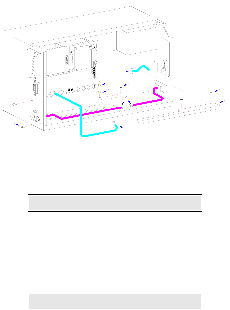
Section 7: Replacement Procedures
M84Pro Service Manual PN 9001111A Page 7-6
Figure 7-5, Power Board Replacement
PANEL BOARD REPLACEMENT
1 Switch off the printer and disconnect the power supply cord.
2 Open/remove the top, right, and left housing covers.
3 Locate panel board (1, Figure 7-6) mounted to the interior of the front cover.
4 Disconnect wiring harnesses (A), (B), and (C).
5 Remove two screws (2) securing panel board (1) to the printer.
6 Manipulate panel board (1) laterally from within the printer.
7 Insert replacement panel board (1) behind the face cover so that the boards buttons are
aligned with their respective slots in the cover.
8 Connect harnesses (C), (B), and (A).
9 Reconnect power supply cord, test cycle, and reattach housing covers.
NOTE: Figure 10-1 of the Daigrams & Schematics section provides guidance
on housing cover removal.
NOTE: Figure 10-1 of the Daigrams & Schematics section provides guidance
on housing cover installation.
INTERFACE
MAIN CIRCUIT BOARD
DAUGHTER
BOARD
POWER BOARD
BOARD
PANEL BOARD
LCD
BELT CONFIGURATION
2
3
5
4
A
C
A
B
B
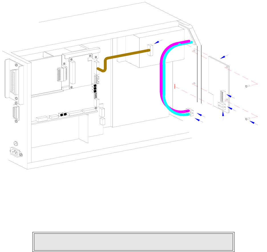
Section 7: Replacement Procedures
M84Pro Service Manual PN: 9001111A Page 7-7
Figure 7-6, Panel Board Replacement
LCD BOARD REPLACEMENT
1 Switch off the printer and disconnect the power supply cord.
2 Open/remove the top, right, and left housing covers.
3 Locate LCD board (1, Figure 7-7) mounted to the interior of the front cover.
4 Disconnect wiring harnesses (A) and (B) from panel board (2).
5 Remove two screws (3) and one plastic washer (4) securing LCD board (1) to the printer.
6 Manipulate LCD board (1) laterally from within the printer.
7 Insert replacement LCD board (1) behind the face cover so that thew LCD is aligned with its
respective slot in the cover.
8 Apply screw (3) into the upper mounting orifice and screw (3) with washer (4) to the lower.
9 Tighten screws (3) securely.
10 Connect LCD wiring harnesses (B) and (A) to panel board (2).
11 Reconnect power supply cord, test cycle, and reattach housing covers.
NOTE: Figure 10-1 of the Daigrams & Schematics section provides guidance
on housing cover removal.
INTERFACE
MAIN CIRCUIT BOARD
DAUGHTER
BOARD
POWER BOARD
BOARD
PANEL BOARD
LCD
BELT CONFIGURATION
B
C2
A
1
A
B
C
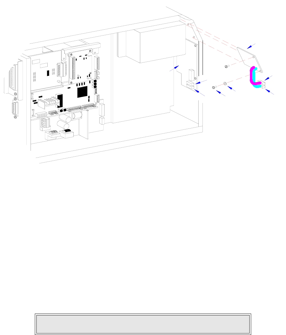
Section 7: Replacement Procedures
M84Pro Service Manual PN 9001111A Page 7-8
Figure 7-7, LCD Board Replacement
FUSE REPLACEMENT
The M84Pro Printer has three fuses; one is externally accessible and is wired to the power
supply while the other two are located internally and directly connected to the main circuit board.
There is an additional fuse integrated into the optional cutter assembly which is easily accessible
by opening the cutter attachment.
This procedure will address only the power supply and circuit board fuses.
1 Switch off the printer and disconnect the power supply cord.
2 Unscrew and remove fuse cap (1, Figure 7-8) and fuse (2) located on the rear printer panel.
3 Remove fuse (2) from fuse cap (1) and determine its condition. Replace as required.
4 Open/remove the top, right, and left housing covers.
5 Locate fuses (3) located on main circuit board (4).
6 Manipulate fuses (3) for their contact clips (5) and determine their condition. Replace as
required.
7 Reconnect power supply cord, test cycle, and reattach housing covers.
NOTE: Figure 10-1 of the Daigrams & Schematics section provides guidance
on housing cover removal.
PANEL BOARD
LCD
BELT CONFIGURATION
BOARD
1
A
B
4
3
A
B
IEEE1284 + RS BOARD
2
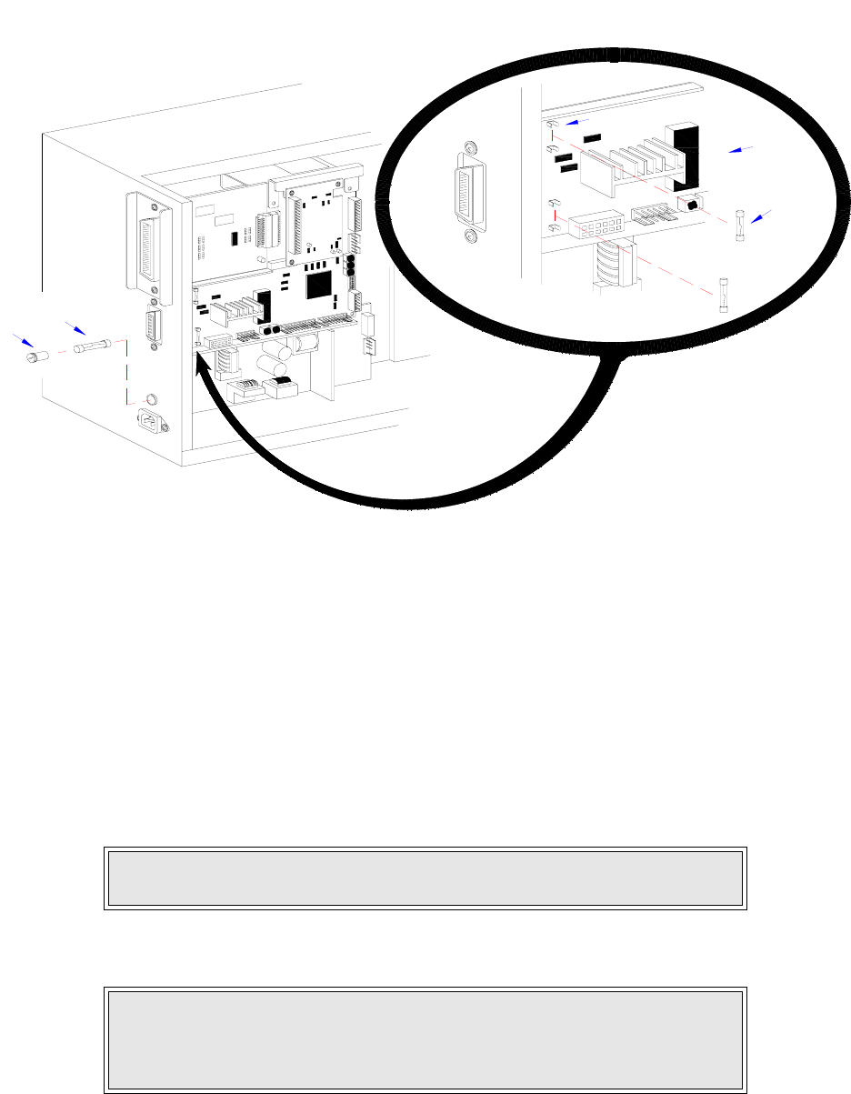
Section 7: Replacement Procedures
M84Pro Service Manual PN: 9001111A Page 7-9
Figure 7-8, Fuse Replacement
MOTOR REPLACEMENT
The stepper motor transmits motion to the print mechanism for precise print positioning. The
energized motor provides torque to the label feed roller, the platen roller, the ribbon feed roller,
and the ribbon rewind spindle via a series of toothed timing belts and gears.
1 Switch off the printer and disconnect the power supply cord.
2 Open/remove the front, top, right, and left housing covers.
3 Locate motor (1, Figure 7-9) position from the left side of the printer.
4 Remove two screws (2) securing motor (1) to the printer frame.
NOTE: Figure 10-1 of the Daigrams & Schematics section provides guidance
on housing cover removal.
NOTE: The left side of the printer contains the circuit board, power board,
and gear configuration. The motor is located on the lower side of the gear
configuration and the motor’s mounting screws are oriented diagonally from
each other on the upper and lower sides of the motor spindle.
IEEE1284 + RS BOARD
3
5
4
2
1
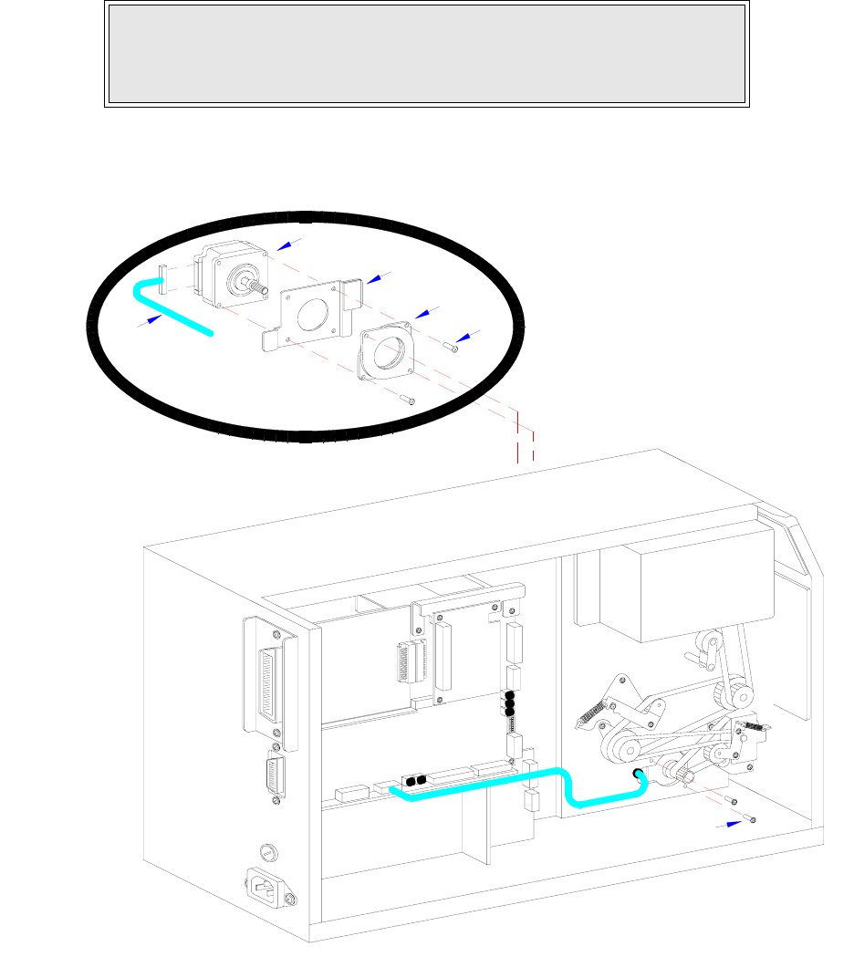
Section 7: Replacement Procedures
M84Pro Service Manual PN 9001111A Page 7-10
5 Remove belt from the motor shaft and withdraw motor (1) to the media side of the printer.
6 Disconnect wiring harness (3) from motor (1).
7 Remove two screws (4) securing damper (5) and heat plate (6) to motor (1).
8 Lift away damper (5), heat sink (6) and withdraw motor (1) from within the printer frame.
9 Insert the replacement motor (1) within the printer frame under the label ramp.
Figure 7-9, Motor Replacement
NOTE: The damper and heat plate must be removed from the motor for the
motor to be withdrawn from within the printer frame. Likewise, the damper
and heat plate must be mounted to the replacement motor with the motor
positioned within the frame.
INTERFACE
MAIN CIRCUIT BOARD
DAUGHTER
BOARD
POWER BOARD
BOARD
BOARD
PANEL
LCD
4
5
6
1
3
2

Section 7: Replacement Procedures
M84Pro Service Manual PN: 9001111A Page 7-11
10 Secure heat plate (6) and damper (5) respectively to motor (1) using two screws (4).
11 Reconnect wiring harness (3) to motor (1).
12 Apply motor (1) against the printer frame oriented so that their mounting orifices are
aligned.
13 Apply drive belt to motor spindle and secure to frame using two screws (2).
14 Adjust belt tension on motor (1) as required in accordance with its relative procedure.
15 Reconnect power supply cord, test cycle, and reattach/close all covers.
PLATEN ROLLER REPLACEMENT
The platen roller is considered to be a high wear component due to its treading against the print
media. This treading contact will eventually wear grooves into the rubber material and negatively
effect print output.
1 Switch off the printer and disconnect the power supply cord.
2 Open or remove the front, top, right, and left housing covers.
3 Remove ribbon and media to provide free access to platen roller (1, Figure 7-10).
4 Loosen or remove screw (2) securing clamp (3) to right roller spindle.
5 Remove e-clip (4) and the outer belt (not shown) from the left roller spindle and pulley (5).
6 Withdraw pulley (5) from left platen roller spindle and inner belt (not shown).
7 Loosen screw and clamp (not shown) on the left end of roller spindle.
8 Withdraw platen roller (1) along with left and right bushings (6) and gear (7) from the printer.
9 Assemble replacement roller as required with gear (7) and bushings (6).
10 Insert the long spindle of platen roller (1) into housing frame so that it protrudes to the drive
side.
11 Allow platen roller (1) to be suspended with its bushings (6) nested on the printer frame.
NOTE: The damper and heat sink require mounting in specific orientation.
Regard Figure 6-9 carefully for the correct orientation.
NOTE: Figure 10-1 of the Daigrams & Schematics section provides guidance
on housing cover installation.
NOTE: Figures 10-1, 10-2, and 10-3 of the Daigrams & Schematics section
provide guidance on housing cover, media, and ribbon removal.
NOTE: The bushings must be installed onto the ends of platen roller with
their flanged sides oriented outward. The cog must be installed so its wider
sleeve is oriented outward.
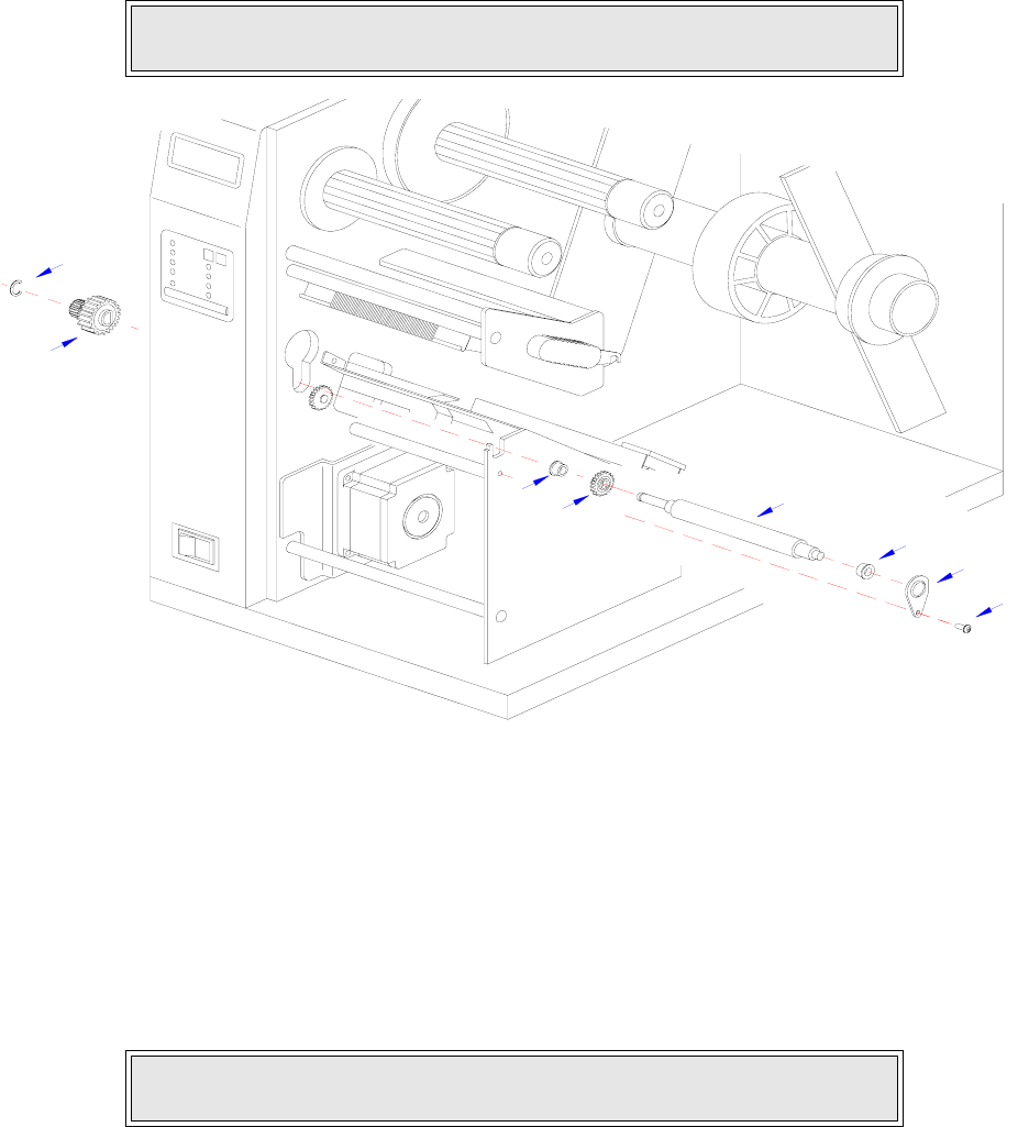
Section 7: Replacement Procedures
M84Pro Service Manual PN 9001111A Page 7-12
12 Secure each end of platen roller (1) with clamps (3) and screws (2).
13 Insert pulley (5) onto the left spindle and apply inner belt (not shown).
14 Apply outer belt (not shown) to gear (5) and e-clip (4) to left roller spindle.
15 Adjust belt tension as required in accordance with its relative procedure.
16 Reconnect power supply cord, test cycle, and reattach/close all covers.
Figure 7-10, Platen Roller Replacement
FEED ROLLER REPLACEMENT
The feed roller is considered to be a high wear component due to its treading against the print
media. This treading contact will eventually wear grooves into the rubber material and negatively
effect print output.
1 Switch off the printer and disconnect the power supply cord.
2 Open or remove the top, right, and left housing covers.
3 Remove ribbon and media to provide free access to drive roller (1, Figure 7-11).
NOTE: Figures 10-1, 10-2, and 10-3 of the Daigrams & Schematics section
provides guidance on housing cover, media, and ribbon installation.
NOTE: Figures 10-1, 10-2, and 10-3 of the Daigrams & Schematics section
provide guidance on housing cover, media, and ribbon removal.
2
3
6
1
6
7
5
4
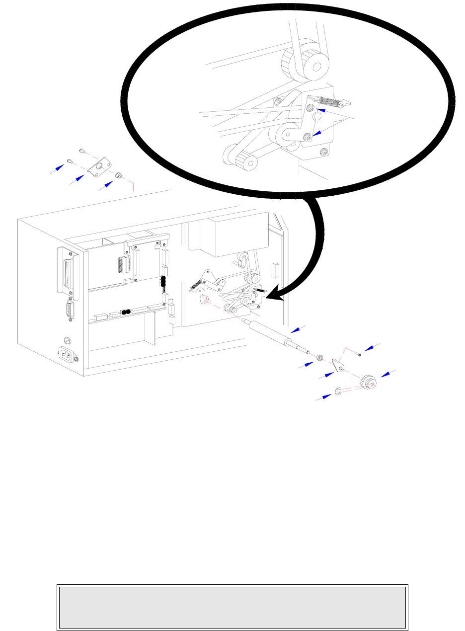
Section 7: Replacement Procedures
M84Pro Service Manual PN: 9001111A Page 7-13
Figure 7-11, Feed Roller Replacement
4 Loosen two screws (2) to release belt tension on drive roller (1).
5 Loosen or remove two screws (3) securing clamp (4) to the right end of drive roller (1).
6 Remove e-clip (5) and the outer belt (not shown) from the left end of drive roller (1) and pul-
ley (6).
7 Withdraw pulley (6) from left drive roller spindle and inner belt (not shown).
8 Loosen screw (7) and clamp (8) on the left end of drive roller (1).
9 Withdraw drive roller (1) along with left and right bushings (9) from the printer.
10 Assemble replacement roller as required with bushings (9).
NOTE: The bushings must be installed onto the ends of drive roller with their
flanged sides oriented outward. The pulley must be installed so its wider
sleeve is oriented outward.
INTERFACE
MAIN CIRCUIT BOARD
DAUGHTER
BOARD
POWER BOARD
BOARD
6
2
7
1
9
8
5
9
4
3

Section 7: Replacement Procedures
M84Pro Service Manual PN 9001111A Page 7-14
11 Insert the short spindle of drive roller (1) into housing frame so that it rests on the far side of
the label ramp secure using clamp (4) and two screws (3).
12 Insert clamp (8) onto the left end of drive roller (1) and secure to the frame using screw (7).
13 Insert pulley (6) onto the left end of drive roller (1) and apply inner belt (not shown).
14 Apply outer belt (not shown) to pulley (6) and e-clip (5) to left roller spindle.
15 Adjust belt tension in accordance with its relative procedure in the Adjustment Procedures
section of this manual.
16 Reconnect power supply cord, test cycle, and reattach/close all covers.
TIMING BELT REPLACEMENT
The M84pro Printer utilizes four timing belts coupled with dual action toothed pulleys to provide
drive distribution throughout the assembly. Two belts are configured to transfer torque from the
motor to the label feed roller. A third belt transfers torque from the feed roller to the platen roller.
And the fourth transfers torque from the platen roller to the ribbon rewind spindle. All four
operating in conjunction provide the total drive configuration for the primary machine.
The optional cutter assembly has its own drive mechanism that operates when directed by the
printer, but independently of the printer drive assembly. The cutter drive assembly also
comprises drive belts and pulleys. Those will not be addressed in this procedure.
1 Switch off the printer and disconnect the power supply cord.
2 Open/remove the top, right, and left housing covers.
3 Disconnect all wiring harnesses that pose an obstruction to belt removal.
4 Remove two screws (1, Figure 7-12a) securing pulley bracket (2) to the printer frame.
5 Withdraw bracket (2) along with belts (3) and (4) from motor spindle (5) and feed roller pul-
ley (6) respectively.
NOTE: Figures 10-1, 10-2, and 10-3 of the Daigrams & Schematics section
provides guidance on housing cover, media, and ribbon installation.
NOTE: Figure 10-1 of the Daigrams & Schematics section provides guidance
on housing cover removal.
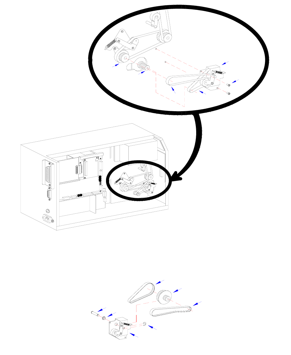
Section 7: Replacement Procedures
M84Pro Service Manual PN: 9001111A Page 7-15
Figure 7-12a, Motor and Feed Belt Replacement
Figure 7-12b, Motor and Feed Belt Replacement
6 Remove e-clip (7, Figure 7-12b), pin (8), and bushing (9) from pulley bracket (2) to free
transition pulley (10), and belts 3, 4.
INTERFACE
MAIN CIRCUIT BOARD
DAUGHTER
BOARD
POWER BOARD
BOARD
2
1
43
5
6
10
3
4
8
9
2
7
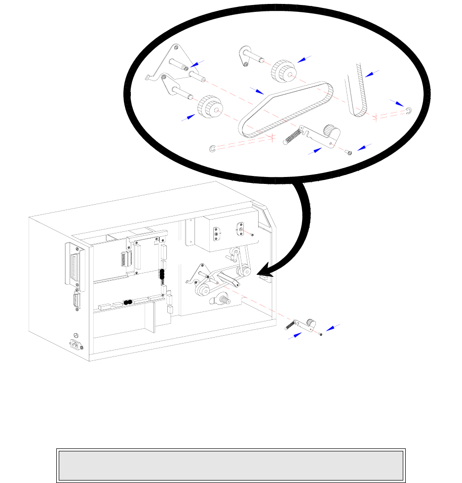
Section 7: Replacement Procedures
M84Pro Service Manual PN 9001111A Page 7-16
Figure 7-12c, Platen Roller Belt Replacement
7 Remove screw (11, Figure 7-12c) and loosen screw (12) to free pulley tension bracket (13).
8 Remove platen roller belt (14) and ribbon rewind belt (15) from feed roller pulley (16) and
platen roller pulley (17) respectively.
9 Remove two screws (19, Figure 7-12d) and four screws (20) and withdraw ribbon frame
(21).
10 Remove ribbon rewind belt (15) from ribbon rewind spindle pulley (22).
11 Prepare to replace timing belts (3), (4), (14), and (15).
12 Apply replacement belt (15) to pulley (22) and allow to suspend.
13 Apply ribbon frame (21) to the printer frame and secure using four screws (20) and two
screws (19).
NOTE: Remove e-clips (18) if removal or replacement of pulleys (16) and
(17) is required.
INTERFACE
MAIN CIRCUIT BOARD
DAUGHTER
BOARD
POWER BOARD
BOARD
15
17
11
14
12
16
13
18
11
13
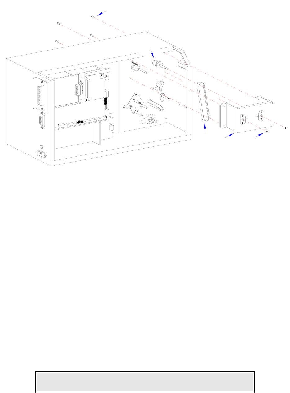
Section 7: Replacement Procedures
M84Pro Service Manual PN: 9001111A Page 7-17
Figure 7-12d, Ribbon and Rewind Belt Replacement
14 Apply belt (14, Figure 6-12c) to the large diameter of pulleys (17) and (16).
15 Apply the lower end of belt (15) to the smaller diameter of pulley (17).
16 Apply pulley tension bracket (13) so that its pulley is oriented under the upper span of belt
(14) and secure using screw (11).
17 Manipulate pulley tension bracket (13) so as to apply tension to belt (14) and tighten screw
(12).
18 Apply replacement belts (4, Figure 7-12b) and (3) to pulley (10) and insert into pulley
bracket (2).
19 Apply bushing (9) to pin (8) and insert through bracket (2) and pulley (10) from the rear.
20 Secure pin (8) at the face of bracket (2) using e-clip (7).
21 Apply the free ends of belts (4, Figure 7-12a) and (3) to feed roller pulley (6) and motor
spindle (5) respectively.
22 Secure pulley bracket (2) to printer frame using two screws (1).
23 Adjust belt tension in accordance with its relative procedure in the Adjustment Procedures
section of this manual.
24 Reconnect all wiring harnesses as directed in Figure 7-13.
25 Reconnect power supply cord, test cycle, and reattach/close all covers.
NOTE: Figure 10-1 of the Daigrams & Schematics section provides guidance
on housing cover installation.
INTERFACE
MAIN CIRCUIT BOARD
DAUGHTER
BOARD
POWER BOARD
BOARD
22
20
15 21 19
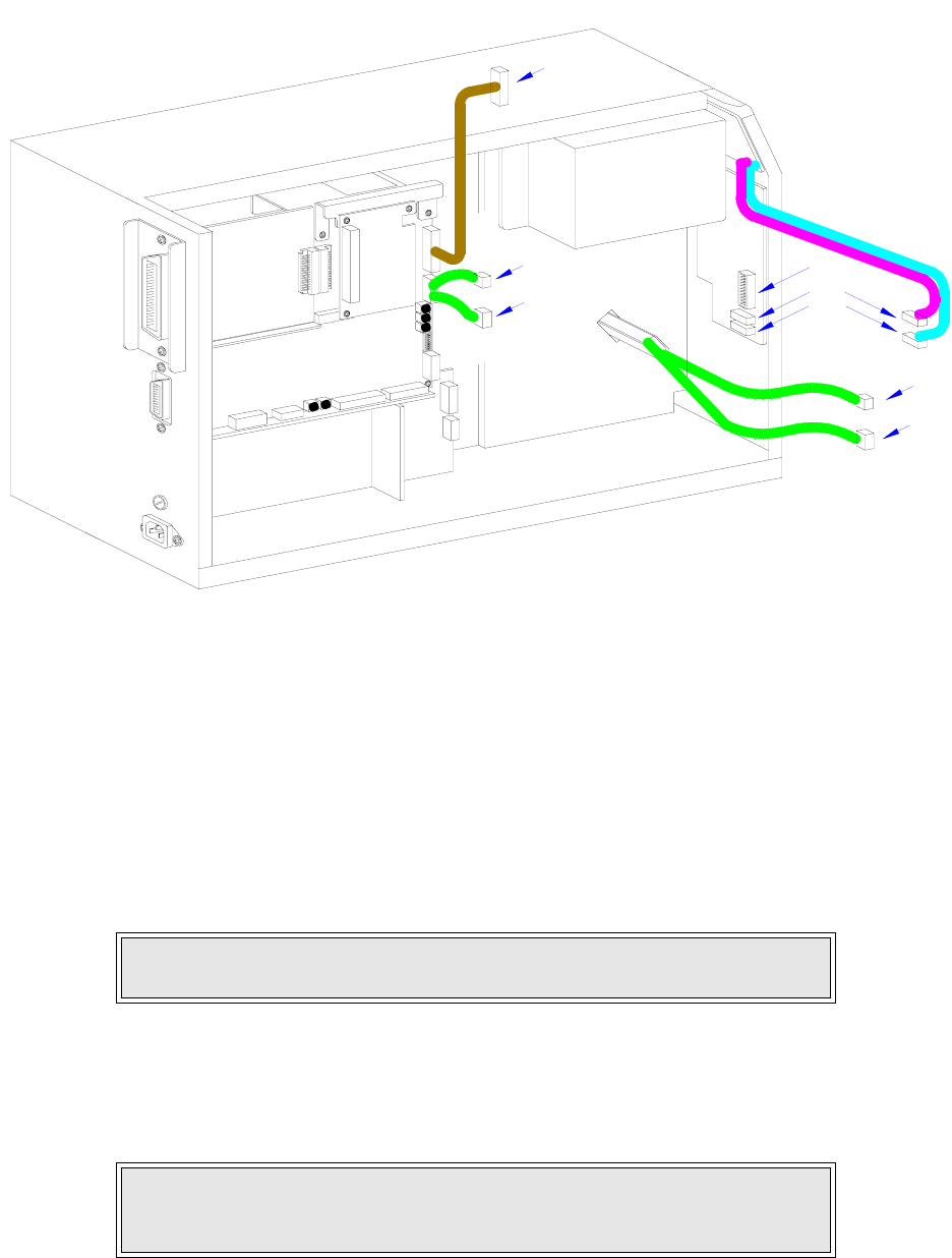
Section 7: Replacement Procedures
M84Pro Service Manual PN 9001111A Page 7-18
Figure 7-13, Wiring Harness Connection
PRINT HEAD REPLACEMENT
If the print head becomes damaged or wears out, it can be easily removed and replaced without
having to make critical adjustments. Before replacing the print head, check the head counter
values by printing a test pattern.
1 Switch off the printer and disconnect the power supply cord.
2 Open/remove the top, right, and front housing covers.
3 Remove ribbon and media to provide free access to print head (1, Figure 7-14).
4 Turn thumb screw (2) located on the top side print assembly (3) to release print head (1).
5 Disconnect the two wiring harnesses from print head (1) and lift away.
NOTE: Figures 10-1, 10-2, and 10-3 of the Daigrams & Schematics section
provides guidance on housing cover, media, and ribbon removal.
NOTE: It is recommended that print head mounting plate (4) be removed
from the damaged print head (1) and saved as a spare. The mounting plate
may be removed by removing two screws (5).
INTERFACE
MAIN CIRCUIT BOARD
DAUGHTER
BOARD
POWER BOARD
BOARD
BELT CONFIGURATION
BELT CONFIGURATION
BELT CONFIGURATION
BELT CONFIGURATION
PANEL BOARD
LCD
B
A
C
A
D
E
D
E
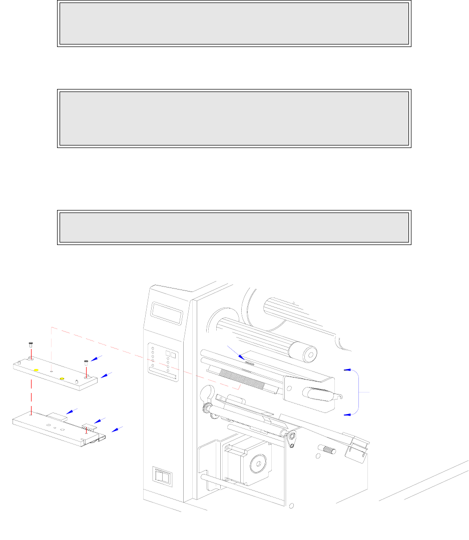
Section 7: Replacement Procedures
M84Pro Service Manual PN: 9001111A Page 7-19
6 Connect the power harness to the larger connector (6) and the thermal head harness to the
smaller connector (7) of replacement print head (1) with the head oriented downward.
7 Apply print head (1) with mounting plate (4) attached, to lower side of print assembly (3).
8 Secure replacement print head (1) to print assembly using thumb screw (2).
9 Clear the print head counter. Refer to the relative procedure for instructions if required.
10 Reconnect power supply cord, test cycle, and reattach/close all covers.
Figure 7-14, Print Head Replacement
NOTE: When the print head is properly oriented under the print assembly,
two colored alignment dots may be seen through two slots when peering
downward from the top side.
CAUTION: ENSURE THAT THE WIRING HARNESSES ARE ROUTED IN A
MANNER SO AS TO PREVENT PINCHING AND THAT THEY DO NOT
TOUCH THE HEAD OPENING SPRING. ALSO CONFIRM THAT THE HEAD
MAY BE OPENED AND CLOSED WITHOUT RESTRICTION.
NOTE: Figures 10-1, 10-2, and 10-3 of the Daigrams & Schematics section
provides guidance on housing cover, media, and ribbon installation.
1
3
2
6
7
5
4
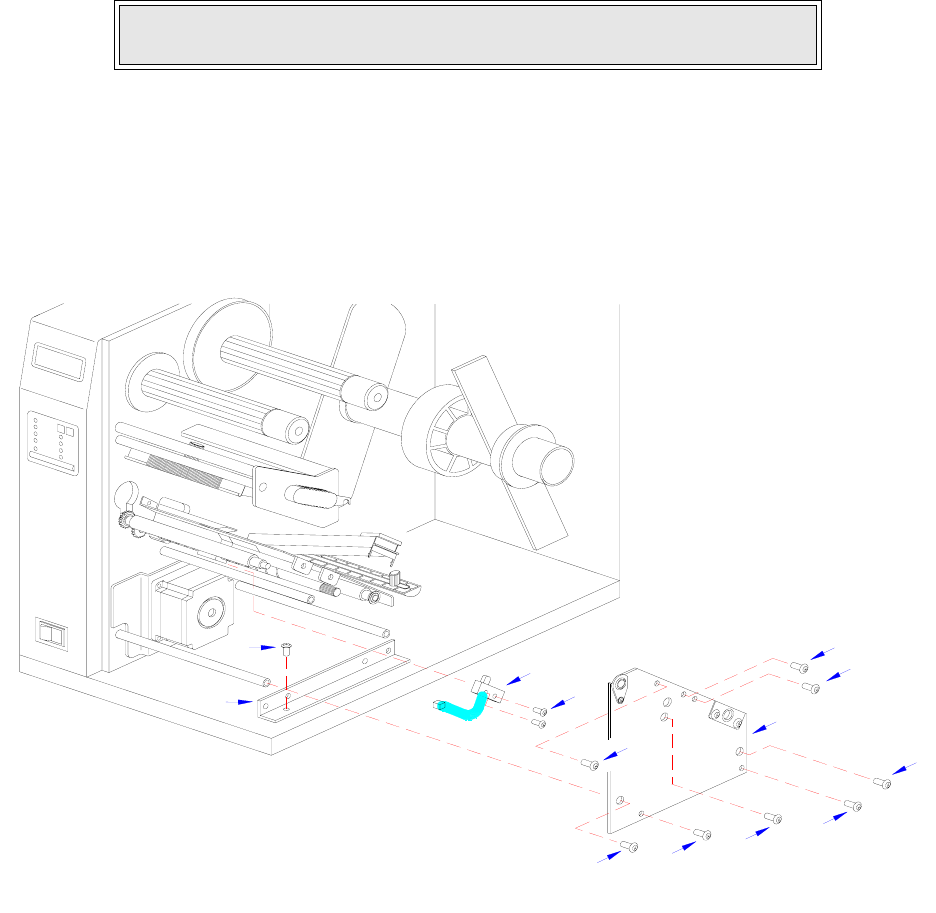
Section 7: Replacement Procedures
M84Pro Service Manual PN 9001111A Page 7-20
LABEL-OUT SENSOR SWITCH REPLACEMENT
The label-out sensor switch detects the presence of print media and sends an error signal to the
processor should the absence of print media be detected. The switch is of a simple on/off variety
that is wired. If print media is present it will depress the switch into the closed position. However,
if print media is not present, the switch will not be depressed and the non-depress state is the on
position.
1 Switch off the printer and disconnect the power supply cord.
2 Open or remove the top, left, right, and front housing covers.
3 Remove ribbon and media to provide free access to label-out sensor (1, Figure 7-15).
4 Remove two screws (2), (3), and (4) from side frame (5).
5 Remove one screw (6) from side frame bracket (7) to permit side frame (5) removal.
6 Remove two screws (8) securing label-out sensor switch (1).
Figure 7-15, Label-Out Sensor Switch Replacement
NOTE: Figures 10-1, 10-2, and 10-3 of the Daigrams & Schematics section
provides guidance on housing cover, media, and ribbon removal.
2
3
2
8
1
5
4
3
4
3
6
7
2
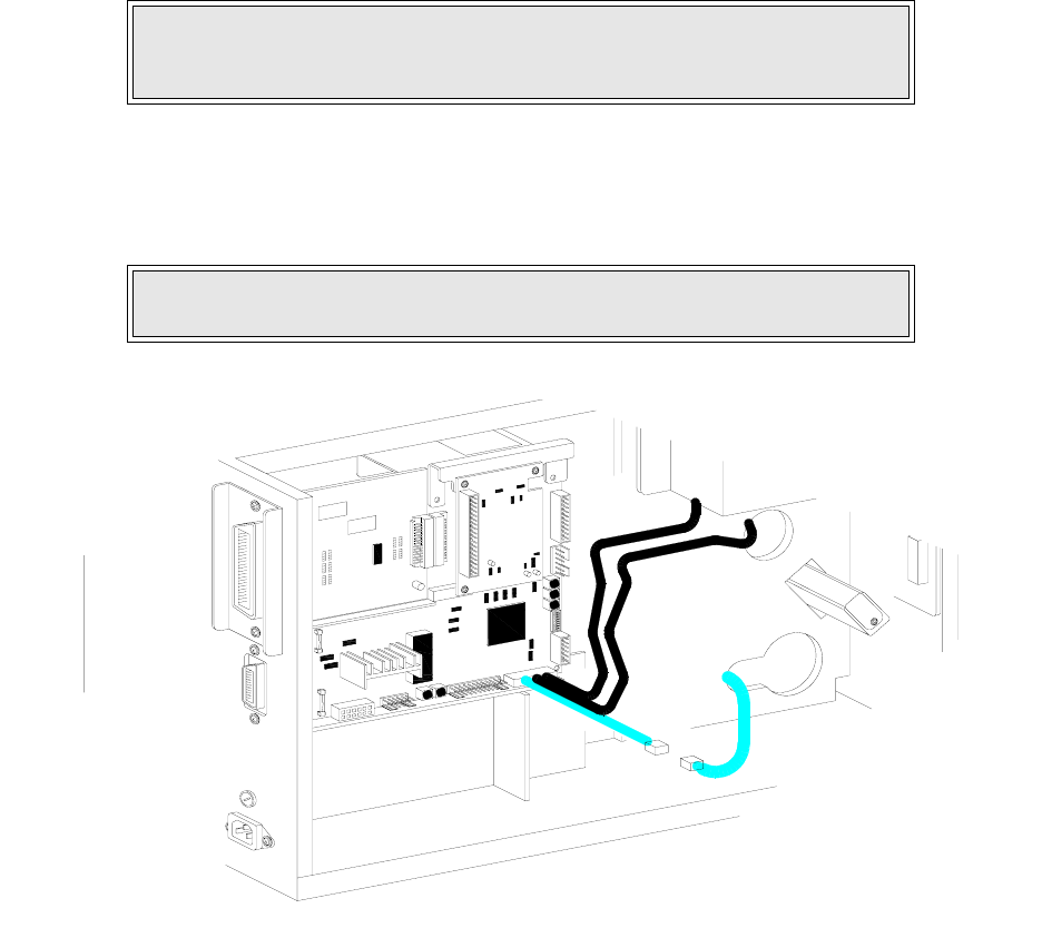
Section 7: Replacement Procedures
M84Pro Service Manual PN: 9001111A Page 7-21
7 Disconnect the sensor switch wiring harness from the main circuit board and withdraw
switch (1) from printer.
8 Feed the wiring harness of replacement switch (1) through the slot adjacent to the motor.
9 Apply switch (1) against the printer frame and secure using two screws (8).
10 Connect the wiring harness of replacement label-out sensor switch (1) to the main circuit
board. Refer to Figure 7-16 for guidance.
11 Reconnect power supply cord, test cycle, and reattach/close all covers.
Figure 7-16, Wiring Harness Connection
NOTE: A properly oriented sensor switch will permit its mounting orifices to
align with those of the frame while its contact arm protrudes through the
paper ramp.
NOTE: Figures 10-1, 10-2, and 10-3 of the Daigrams & Schematics section
provides guidance on housing cover, media, and ribbon installation.
IEEE1284 + RS BOARD
POWER BOARD
BELT CONFIGURATION
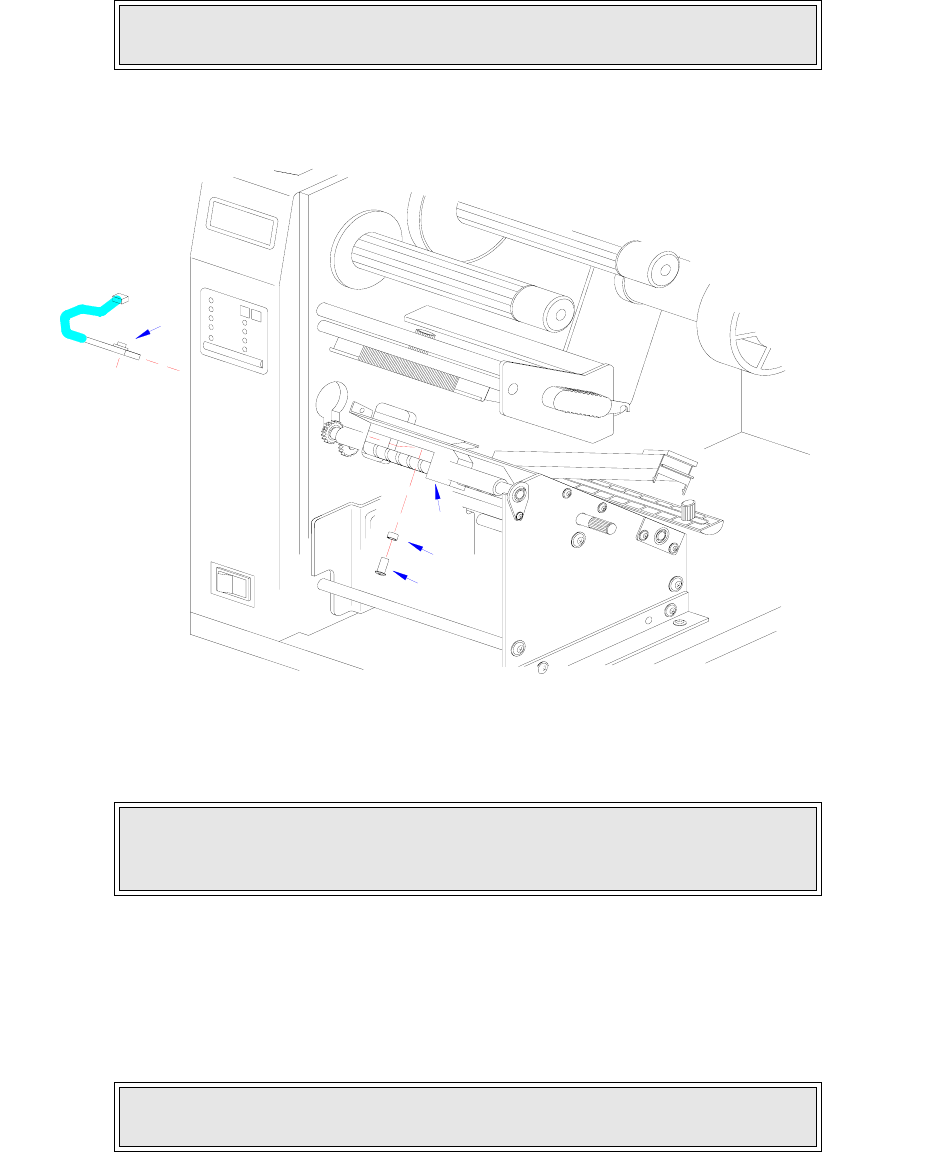
Section 7: Replacement Procedures
M84Pro Service Manual PN 9001111A Page 7-22
LABEL POSITION SENSOR REPLACEMENT
1 Switch off the printer and disconnect the power supply cord.
2 Open or remove the top, left, right, and front housing covers.
3 Remove ribbon and media to provide free access to label position sensor (1, Figure 7-17).
Figure 7-17, Label Position Sensor Replacement
4 Remove screw (2) and nylon spacer (3) securing sensor (1) to media sensor guide (4).
5 Disconnect wiring harness of damaged sensor (1) from the main circuit board.
6 Connect the wiring harness of replacement label position sensor (1) to main circuit board.
Refer to Figure 7-18 for guidance.
7 Reconnect power supply cord, test cycle, and reattach/close all covers.
NOTE: Figures 10-1, 10-2, and 10-3 of the Daigrams & Schematics section
provides guidance on housing cover, media, and ribbon removal.
NOTE: The sensor is attached to the underside of the sensor guide. The sen-
sor guide is manufactured of black phenolic material and is attached to the
brass auger type spindle.
NOTE: Figures 10-1, 10-2, and 10-3 of the Daigrams & Schematics section
provides guidance on housing cover, media, and ribbon installation.
1
3
2
4
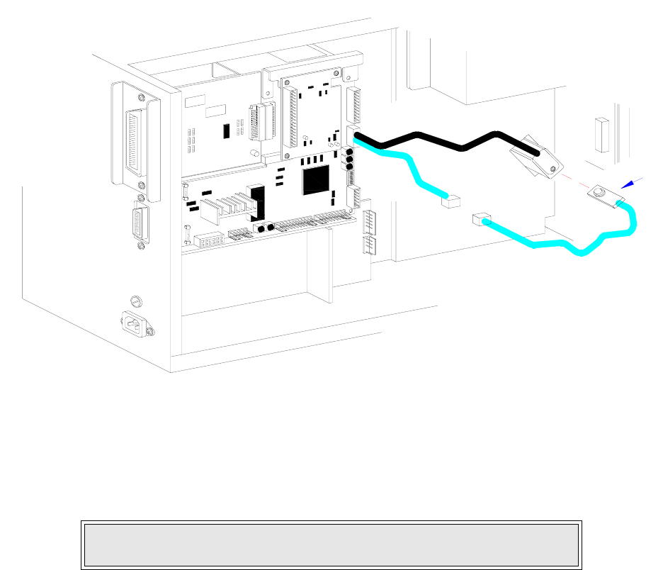
Section 7: Replacement Procedures
M84Pro Service Manual PN: 9001111A Page 7-23
Figure 7-18, Wiring Harness Connection
RIBBON SENSOR REPLACEMENT
1 Switch off the printer and disconnect the power supply cord.
2 Open or remove the top, left, and right housing covers.
3 Remove ribbon to allow access to ribbon sensor (1, Figure 7-21) and supply assembly (2).
4 Remove screw (3) and screw (4) from ribbon supply assembly (2).
5 Withdraw boss cap (5), two collars (6), ribbon boss (7), another collar (6), and disk plate (8)
from ribbon supply shaft (9) consecutively.
6 Disconnect the wiring harness of ribbon sensor (1) from the main circuit board.
7 Remove screw (10) securing ribbon sensor (1) to printer frame. Lift away sensor (1).
8 Route replacement sensor (1) through printer frame.
9 Secure replacement sensor (1) to printer frame using screw (10).
10 Apply disk plate (8), a collar (6), ribbon boss (7), two additional collars (6), and boss cap (5)
onto ribbon supply shaft (9) and secure with screw (4).
11 Align orifices of boss (7) and shaft (9) and apply screw (3).
12 Connect wiring harness of replacement ribbon sensor (1) to main circuit board. Refer to
Figure 7-22 for guidance.
NOTE: Figures 10-1 and 10-3 of the Daigrams & Schematics section pro-
vides guidance on housing cover and ribbon removal.
IEEE1284 + RS BOARD
BELT CONFIGURATION
1
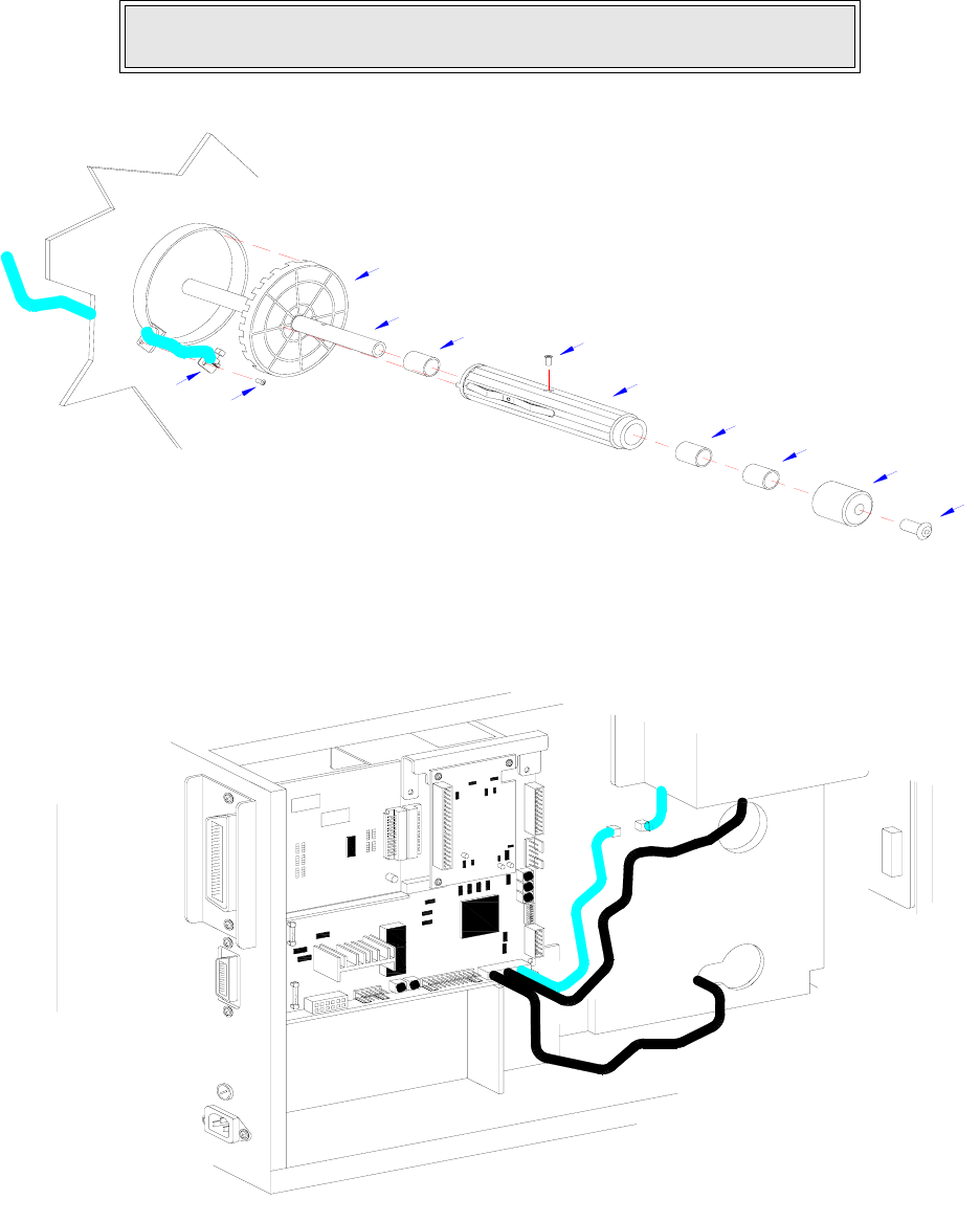
Section 7: Replacement Procedures
M84Pro Service Manual PN 9001111A Page 7-24
13 Install ribbon, restore power, test cycle, and install/close housing covers.
Figure 7-21, Ribbon Sensor Replacement
Figure 7-22, Wiring Harness Connection
NOTE: Figures 10-1 and 10-3 of the Daigrams & Schematics section pro-
vides guidance on housing cover and ribbon installation.
4
5
6
6
7
3
6
9
8
1
10
IEEE1284 + RS BOARD
POWER BOARD
BELT CONFIGURATION

Section 7: Replacement Procedures
M84Pro Service Manual PN: 9001111A Page 7-25
CUTTER BELT REPLACEMENT
The cutter assembly is an accessory to the printer. As a purchase option, the cutter assembly
may not apply to the printer in question. The cutter assembly mounts to the face of the printer in
place of the standard front cover.
1 Switch off the printer and disconnect the power supply cord.
2 Remove cutter assembly (1, Figure 7-23a) from the printer.
3 Remove two screws (2) securing idle gear bracket (3) and lift away.
4 Withdraw cutter timing belt (4) and motor timing belt (5) from cutter assembly (1).
5 Apply replacement motor belt (5) to motor pulley (6) and idle pulley (7).
6 Apply replacement cutter belt (4) to idle pulley (7) and cutter pulley (8).
7 Apply bracket (3) to the assembly oriented as removed and secure using two screws (2).
8 Prepare to replace o-ring belt (9, Figure 7-23b).
9 Remove two screws (10) and two screws (11) from left and right sides of cutter frame (12).
10 Lift cutter cover (13) away from cutter frame (12).
11 Loosen screws (14), (15), (16), (17), and (18) located on the right side of cutter frame (12)
sufficiently to manipulate the right end of feed roller (19) free.
12 Remove worn o-ring belt (9) from feed roller (19) and stepper motor (20).
13 Apply replacement o-ring belt (9) to feed roller (19) and stepper motor (20).
14 Insert right end of feed roller (19) into cutter frame (12) and tighten screws (18), (17), (16),
(15), and (14).
15 Apply cutter cover (13) to cutter frame (12) and secure with two screws (11) and (10) to the
right and left sides respectively.
16 Re-install the cutter assembly, connect power supply cord, and test cycle.
NOTE: If unsure how to remove the cutter assembly, refer to the Label Cutter
Installation procedure in the Accessories Installation section for guidance.
NOTE: When properly installed, the idle bracket gear will apply tension pres-
sure to the outer surface of the cutter belt.
NOTE: Refer to the Label Cutter Installation procedure in the Accessories
Installation section of this manual for installation guidance.
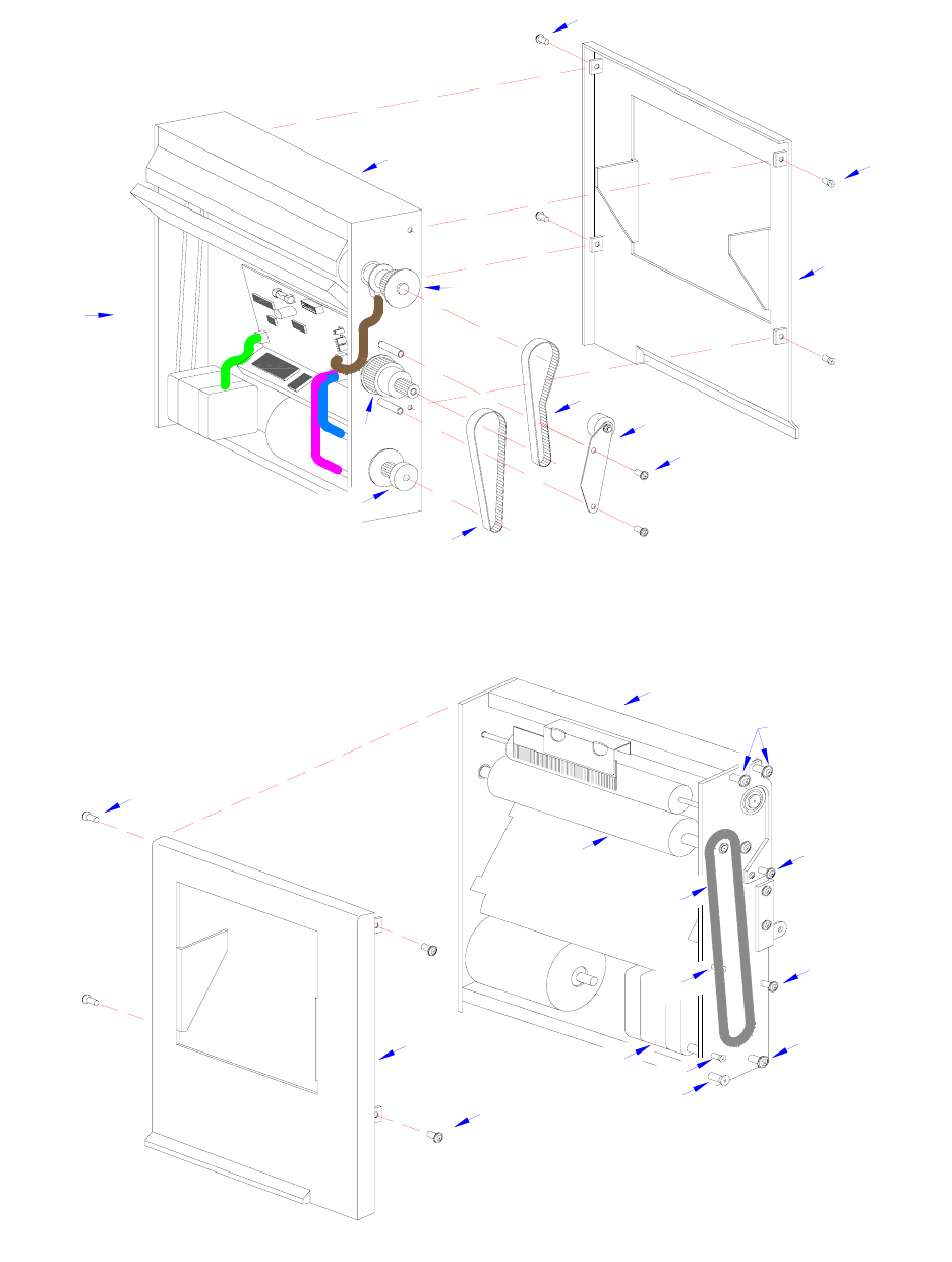
Section 7: Replacement Procedures
M84Pro Service Manual PN 9001111A Page 7-26
Figure 7-23a, Cutter Belt Replacement
Figure 7-23b, Cutter Belt Replacement
10
3
2
11
13
12
4
6
5
8
7
1
15
14
15
16
11
18
18
17
9
13
10
19
20
12
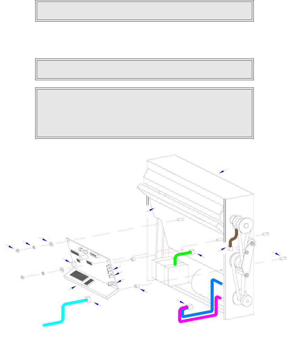
Section 7: Replacement Procedures
M84Pro Service Manual PN: 9001111A Page 7-27
CUTTER CIRCUIT BOARD REPLACEMENT
1 Switch off the printer and disconnect the power supply cord.
2 Remove cutter assembly (1, Figure 7-24) from the printer.
3 Disconnect all wiring harnesses from circuit board (2).
4 Remove two screws (3) from paper guide plate (4).
Figure 7-24, Cutter Circuit Board Replacement
NOTE: If unsure how to remove the cutter assembly, refer to the Label Cutter
Installation procedure in the Accessories Installation section for guidance.
NOTE: The two screws that are to be removed from the paper guide plate are
located on the front side of the cutter along the lower perimeter of the plate.
CAUTION: WHEN THE TWO SCREWS ARE REMOVED FROM THE
PAPER GUIDE PLATE, TWO NYLON SPACERS LOCATED BETWEEN
THE CIRCUIT BOARD AND THE PLATE WILL BE FREED. ENSURE THAT
THE CUTTER ASSEMBLY IS HORIZONTAL WITH THE CIRCUIT BOARD
ORIENTED UPWARD WHEN THE BOARD IS REMOVED TO PREVENT
THEIR LOSS.
1
B
C
8
2
A
7
6
D
5
A
C
B
D
3
2

Section 7: Replacement Procedures
M84Pro Service Manual PN 9001111A Page 7-28
5 Remove two nuts (5), lock washers (6), and flat washers (7) from circuit board (2).
6 Manipulate damaged cutter circuit board (2) from cutter assembly (1).
7 Retrieve two nylon spacers (8) from within cutter assembly (1).
8 Apply and hold two screws (3) to paper guide plate (4) from the exterior.
9 Apply a nylon spacer (8) to each screw (3) from the interior.
10 Thread screws (3) into circuit board (2).
11 Apply flat washers (7), lock washers (6), and nuts (5) consecutively to circuit board (2).
12 Connect wiring harnesses to replacement circuit board.
13 Re-install the cutter assembly, connect power supply cord, and test cycle.
CAUTION: IT IS RECOMMENDED THAT STEPS 8 THROUGH 10 BE PER-
FORMED OVER A TABLE. GREAT DEXTERITY IS REQUIRED AND THE
POTENTIAL FOR COMPONENT LOSS IS HIGH.
NOTE: Refer to the Label Cutter Installation procedure in the Accessories
Installation section of this manual for installation guidance.
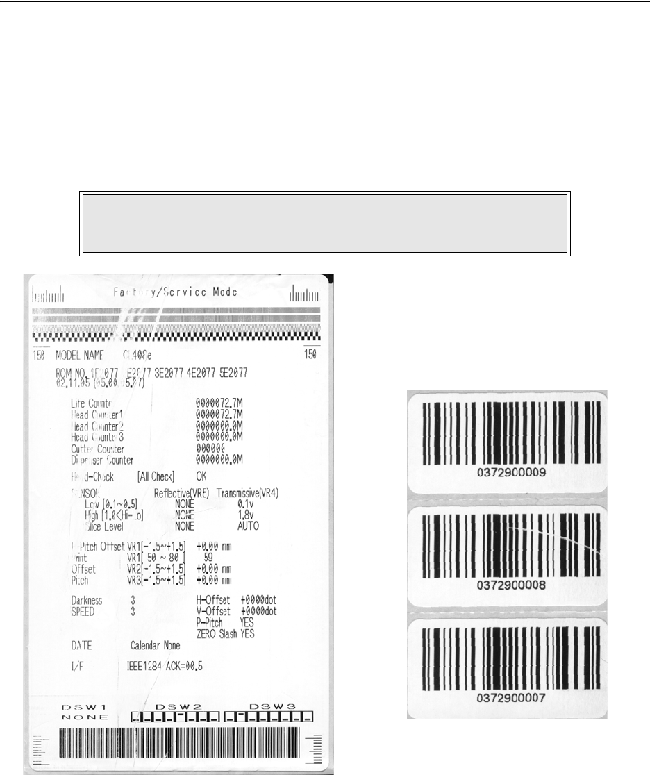
M84Pro Service Manual PN: 9001111A Page 8-1
8
ADJUSTMENT PROCEDURES
The SATO M84pro Printer incorporates a series of sub-assemblies that, in conjunction, comprise
the total printer assembly. Many of these sub-assemblies are designed to be adjustable to
maintain optimum performance of the printer throughout its life. This service manual section
addresses the proper technique for their adjustment.
It may be necessary to refer to this section following component replacement. Use the relative
procedures in that section to replace the component, test cycle the printer, and then adjust as
necessary in accordance to the relative procedures in this section.
Figure 8-1, Print Defects
NOTE: Refer to Figure 10-6, Print Position Reference and Figures 10-7
through 10-19, Print Operation Sequence in the Diagrams & Schematics
section for additional operational data as deemed necessary.
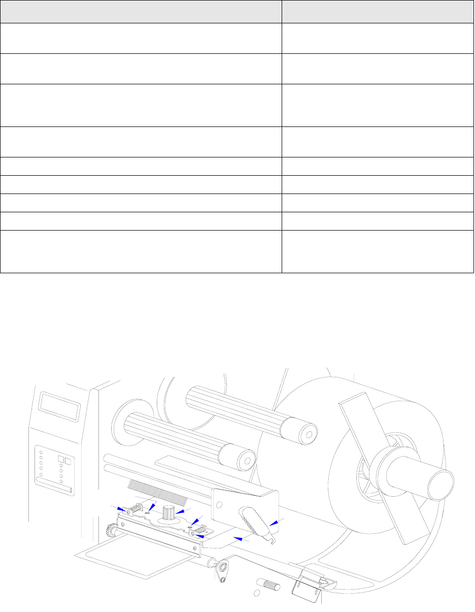
Section 8: Adjustment Procedures
M84Pro Service Manual PN 9001111A Page 8-2
PRINT HEAD POSITION ALIGNMENT
Print head position has a direct impact on print quality. An improperly aligned print head will
cause the print to be inconsistent across the label. The following procedure will provide guidance
on print head alignment.
Figure 8-2, Print Head Alignment
PRINT DEFECTS RELATIVE PROCEDURE
Print becomes lighter or darker from one side to the other.
This condition is repetitive from label to label.
Print Head Balance Adjustment
Voids in the overall print image. This condition is repetitive
from label to label.
Print Darkness Adjustment
A visible path on the label where print image is missing. The
path will change somewhat from label to label.
Print Head Position Alignment
Platen Roller Adjustment
Ribbon Guide Plate Adjustment
The scales at the lower left and right sides are not equal
distances from the labels lower edge.
Print Head Position Alignment
The lines are not sharp. Print Darkness Adjustment
The image is too light. Print Darkness Adjustment
The image is severely dark. Print Darkness Adjustment
Bar code label has a sharp line where print is missing. Print Darkness Adjustment
The printed position is too far in one direction or another. Print Position Adjustment
Feed Roller Adjustment
Offset Label Stop Position
MEDIA
MEDIA
1
4
5
5
3
3
2

Section 8: Adjustment Procedures
M84Pro Service Manual PN: 9001111A Page 8-3
1 Remove ribbon as applicable to gain access to the top side of print head (1, Figure 8-2).
2 Loosen thumbscrew (2) and two set screws (3).
3 Load printer with media and ribbon as applicable and latch (4) print head (1) closed.
4 Begin continuous printing of self-test labels.
5 Adjust left or right screw/s (5) to manipulate print head (1) as deemed necessary until the
print image is deemed acceptable.
6 Retighten two set screws (3) and thumbscrew (2) to complete the adjustment process.
PRINT HEAD BALANCE ADJUSTMENT
Print quality may be further optimized by the adjustment of the print head balance. When the print
head is balanced, there is equal pressure applied across the print media and platen roller by the
print head. The left side of the print head remains fixed and the right side is adjusted vertically to
obtain balance. To adjust print head balance, follow the instructions below.
1 Visually inspect the condition of the feed and platen rollers and replace as necessary.
2 Adjust the feed roller in accordance with its relative procedure in this manual.
3 Load printer with media and ribbon as applicable.
NOTE: Figure 10-3 in the Diagrams & Schematics section provides guidance
on ribbon removal.
NOTE: Figures 10-2 and 10-3 of the Diagrams & Schematics section
provides guidance on media and ribbon installation.
NOTE: The self-test label identifies if any elements are malfunctional. To the
far right of the Head Check row, OK will be printed if elements are not missing
and NG if any are missing. Begin a troubleshooting process should difficulties
be found. It is recommended that the troubleshooting process begin at the
rear of the printer and work forward.
NOTE: The print speed and darkness should be set so as to assist in
determining if the print image is being improved during alignment. The speed
and darkness settings are identified on the self-test label. Adjust as deemed
necessary.
NOTE: The self-test label provides a scale in the lower right and left corners
to assist in adjustment. The label is properly aligned perpendicular to the
print head when the scale increments are proportionate on each side.

Section 8: Adjustment Procedures
M84Pro Service Manual PN 9001111A Page 8-4
4 Begin continuous printing of self-test labels.
5 Loosen paper guide thumbscrew (1, Figure 8-3) and adjust guide fully outward.
6 Loosen set screw (2) to allow the right side of print head (3) to be adjusted.
7 Manipulate screw (4) to adjust print head (3) while observing scale (5) under latch (6).
8 Retighten set screw (3).
NOTE: Figures 10-2 and 10-3 of the Diagrams & Schematics section
provides guidance on media and ribbon installation.
NOTE: The self-test label identifies if any elements are malfunctional. To the
far right of the Head Check row, OK will be printed if elements are not missing
and NG if any are missing. Begin a troubleshooting process should difficulties
be found. It is recommended that the troubleshooting process begin at the
rear of the printer and work forward.
NOTE: The print speed and darkness should be set so as to assist in
determining if the print image is being improved during alignment. The speed
and darkness settings are identified on the self-test label. Adjust as deemed
necessary.
NOTE: The self-test label provides incremented patterns across its upper
and lower perimeters for adjustment assistance. Observe print quality in
these regions during adjustment.
NOTE: By moving the paper guide away from the label’s edge, it allows the
stock to wander. Observe label movement during the printing and adjustment
process for assistance.
NOTE: The left edge of the ribbon should always cover the label’s left edge
by 1/8 inch.
NOTE: Clockwise screw rotation raises the print head on the right side.
Counter-clockwise rotation conversely lowers the print head.
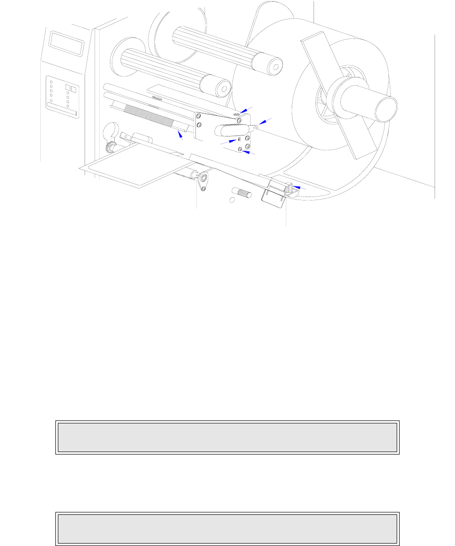
Section 8: Adjustment Procedures
M84Pro Service Manual PN: 9001111A Page 8-5
Figure 8-3, Print Head Balance Adjustment
RIBBON GUIDE PLATE ADJUSTMENT
Ribbon wrinkling has a negative impact on print quality and should be avoided. If ribbon wrinkling
is observed across the ribbon guide plate, adjustment may be necessary. Before adjusting the
ribbon guide plate, it is recommended that the print head balance be adjusted first, followed by
the guide plate if necessary.
The left side of the ribbon guide plate remains fixed and the right side is adjusted vertically. To
adjust the ribbon guide plate, follow the instructions below.
1 Load printer with media and ribbon as applicable.
2 Connect the power supply cord, restore power, and test cycle.
3 Manually manipulate print head latch (1, Figure 8-4) to open print head (2).
4 Loosen set screw (3) to allow the right side of ribbon guide plate (4) to be adjusted.
5 Manipulate guide plate (4) until the ribbon seems to smooth itself out.
6 Retighten screw (3) to hold that position.
NOTE: Figures 10-2 and 10-3 of the Diagrams & Schematics section
provides guidance on media and ribbon installation.
NOTE: The printer will go into a standby mode when the print head is
opened. It is not necessary to turn the printer off.
MEDIA
MEDIA
6
2
5
4
3
1
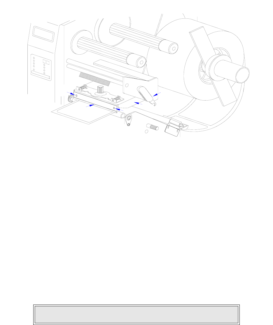
Section 8: Adjustment Procedures
M84Pro Service Manual PN 9001111A Page 8-6
7 Ensure screw (5) is secure on the left side of guide plate (4).
8 Test cycle and readjust as necessary.
Figure 8-4, Ribbon Guide Plate Adjustment
FEED ROLLER ADJUSTMENT
Feed roller adjustment is used for fine tuning label tracking. By adjusting the pressure between
the upper and lower rollers, the media may be directed through the printer as desired. If mal-
adjusted, the label media will have a tendency to want to track to the left or to right depending on
which side has the greatest pressure.
A properly adjusted upper and lower feed roller assembly will have evenly applied pressure to
each side and be properly aligned. The pressure difference between each side should be 100
grams or less. A tension gauge will be required to measure the tension.
To acquire the desired adjustment; the upper, the lower, or both feed rollers may require
manipulation. Each roller may be adjusted along opposing X and Y axis. Different variations may
be required until the correct adjustment is achieved.
1 Switch the printer off and disconnect the power supply cord.
2 Open the top and right side housing covers.
3 Remove label stock from the printer and leave print head open.
4 Attach a strip of 20mm + wide liner backing paper to the end of the tension gauge.
NOTE: Figures 10-1, 10-2, and 10-3 of the Diagrams & Schematics section
provides guidance on housing cover, media, and ribbon removal.
MEDIA
MEDIA
2
1
5
43
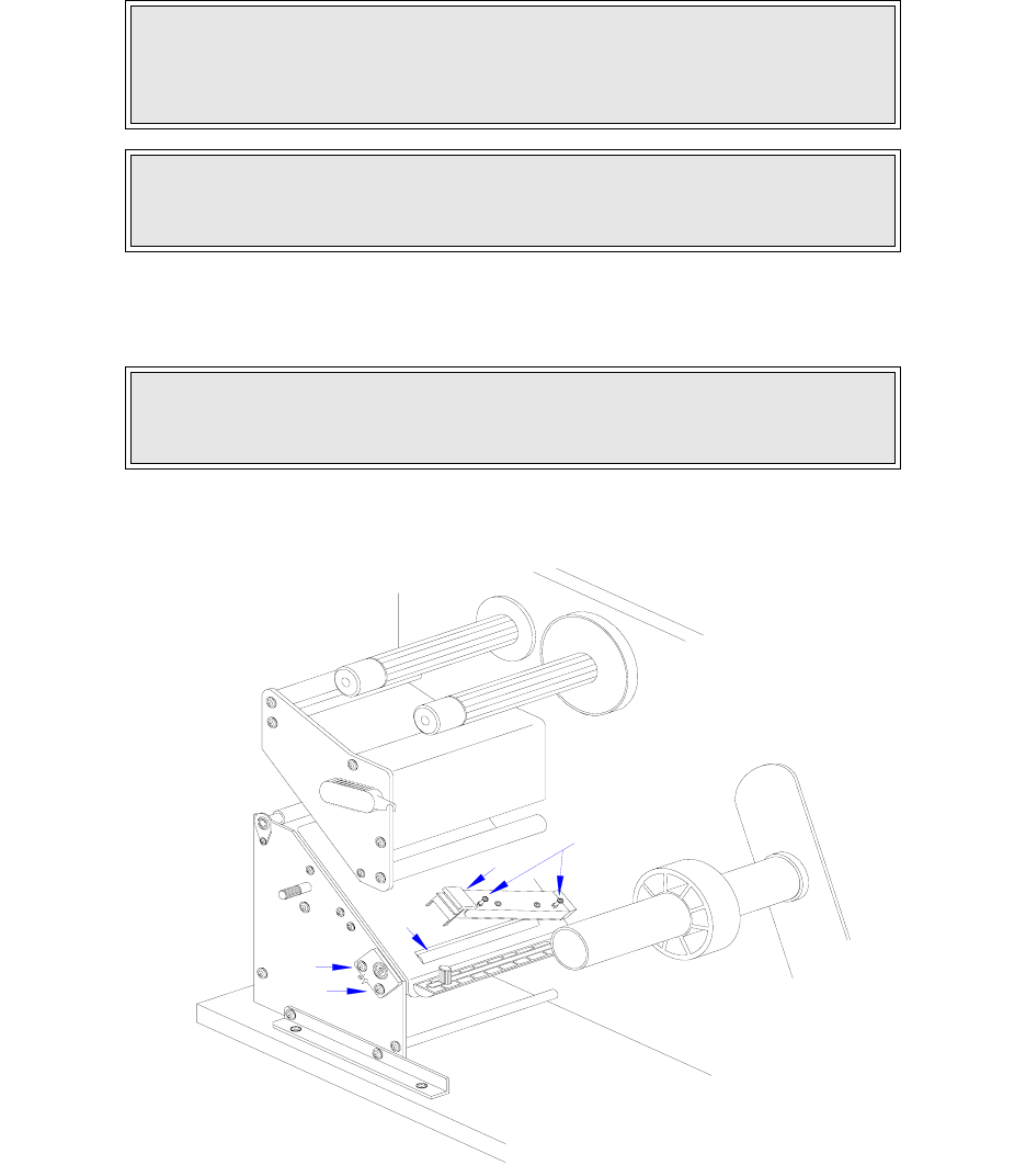
Section 8: Adjustment Procedures
M84Pro Service Manual PN: 9001111A Page 8-7
5 Place the strip between the upper and lower feed rollers on one end and latch media cover.
6 Slowly pull the tension gauge sufficiently enough to take a reading.
7 Repeat steps 5 and 6 for the opposite end of feed roller assemblies.
8 Adjust lower roller (1, Figure 8-5) by slightly loosening two screws (2) securing roller
bracket (3) and adjusting as deemed necessary while observing scale (4).
9 Adjust upper roller (5) by loosening the two lock nuts (6) and adjusting their respective set
screws (7) as deemed necessary. Retighten nuts (6) to secure.
10 Test cycle and readjust as necessary.
Figure 8-5, Feed Roller Adjustment
NOTE: The lower roller may be adjusted by inserting a medium sized
standard screwdriver into the slot located along the lower periphery of the
roller bracket and twisting. The scale is located adjacent to the adjustment
slot.
CAUTION: ONLY ADJUST THE UPPER ROLLER IF IT HAS DEFINATELY
BEEN DETERMINED THAT ADJUSTMENT OF THE LOWER ROLLER
WILL NOT SUFFICE.
NOTE: Each side of the upper roller may be adjusted independently. Only
loosen the lock nut and adjust the set screw on the end of the roller deemed
necessary to adjust.
76,
2
3
1
5
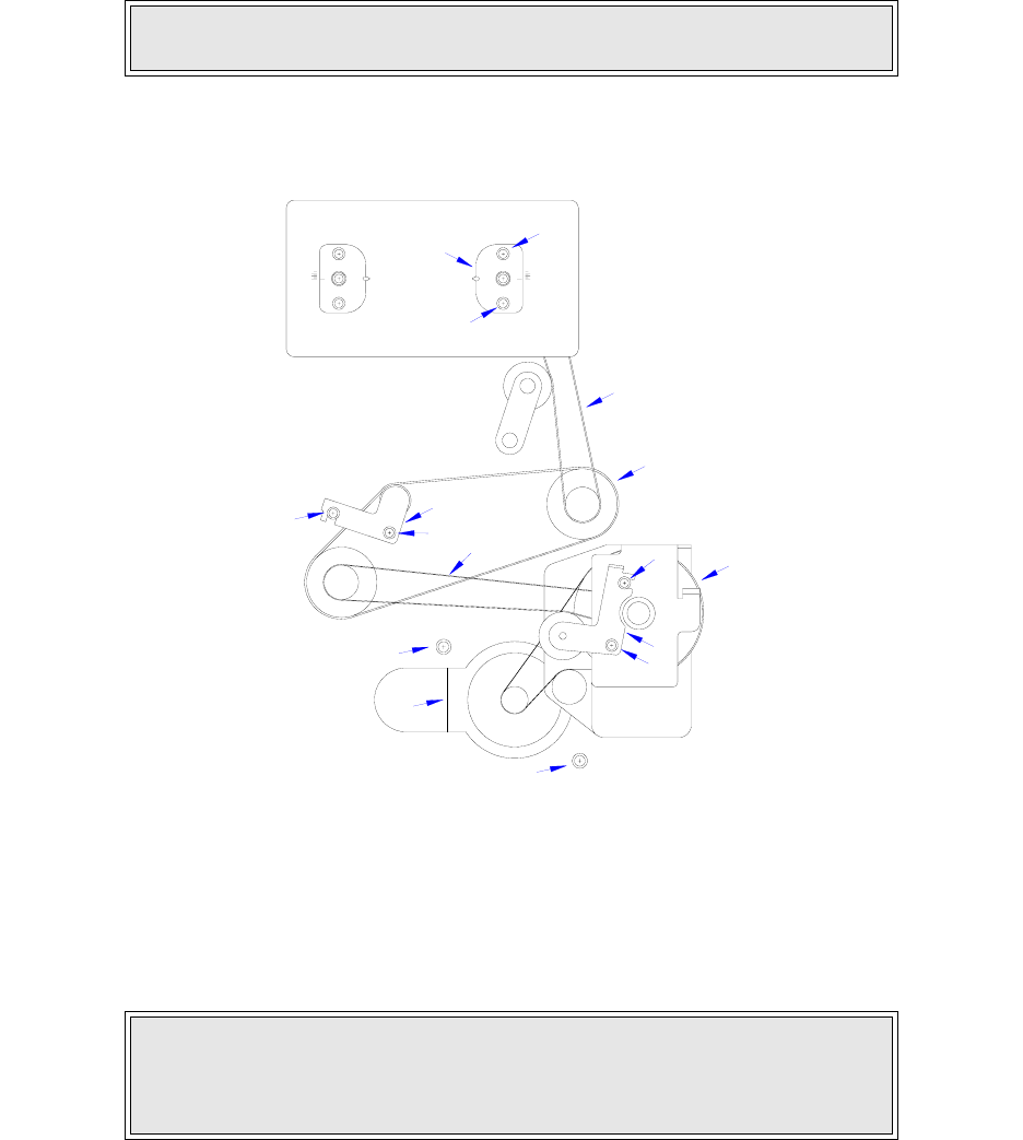
Section 8: Adjustment Procedures
M84Pro Service Manual PN 9001111A Page 8-8
TIMING BELT ADJUSTMENT
The following procedure covers the adjustment of all timing belts within the printer. Not included,
is the adjustment procedure for the optional cutter assembly. However, the adjustment technique
is exactly the same as here. Remove the cutter assembly to gain access to its belts.
1 Switch the printer off and disconnect the power supply cord.
2 Open/remove the top, right, and left housing covers.
3 Loosen two screws (1, Figure 8-6) and manipulate motor (2) as required to tighten motor
belt (3). Retighten screws (1).
Figure 8-6, Tightening Timing Belts
4 Loosen two screws (4) and manipulate bracket (5) as required to tighten feed roller belt (6).
Retighten screws (4).
5 Loosen two screws (7) and manipulate bracket (8) as required to tighten platen roller belt
(9). Retighten screws (7).
NOTE: Figure 10-1 of the Diagrams & Schematics section provides guidance
on housing cover removal.
CAUTION: STEP 6 SHOULD ONLY BE PERFORMED BY FACTORY
PERSONNEL. THIS ADJUSTMENT MAY MAKE MATTERS WORSE BY
AFFECTING RIBBON REWIND ANGLE AND CAUSING RIBBON
WRINKLING.
11
10
12
8
7
7
1
1
3
9
6
4
5
4
2
10
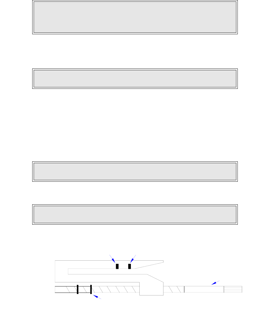
Section 8: Adjustment Procedures
M84Pro Service Manual PN: 9001111A Page 8-9
6 Loosen two screws (10) and manipulate bracket (11) to tighten ribbon rewind belt (12).
Retighten screws (10).
7 Restore power and test cycle to ensure proper function.
8 Close/replace housing covers.
PITCH SENSOR SETUP FOR NOTCH TAGS
The following procedure applies to labels with notches along the left perimeter of the label stock.
Ignore this procedure otherwise.
1 Switch off the printer and disconnect the power supply cord.
2 Remove the front housing cover.
3 Remove e-clip (1, Figure 8-7) from brass sensor adjustment shaft (2) as necessary.
Figure 8-7, Pitch Sensor Assembly
NOTE: The lower roller may be adjusted by inserting a medium sized
standard screwdriver into the slot located along the lower periphery of the
roller bracket and twisting. The scale is located adjacent to the adjustment
slot.
NOTE: Figure 10-1 of the Diagrams & Schematics section provides guidance
on housing cover installation.
NOTE: Figure 10-1 in the Diagrams & Schematics section provides guidance
on housing cover removal.
NOTE: Removal of the e-clip permits the sensor to be adjusted an additional
14mm to the left for tag stock applications.
2
4
3
1
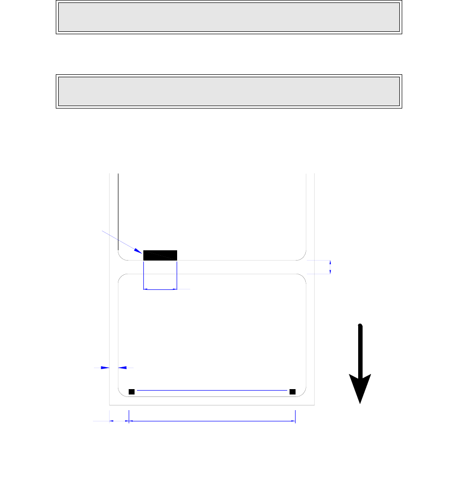
Section 8: Adjustment Procedures
M84Pro Service Manual PN 9001111A Page 8-10
4 Turn the knurled knob of sensor adjustment shaft (2) to laterally adjust sensors (3) and (4).
5 Close/install housing covers.
Figure 8-8, Label Stock Diagram
PRINT POSITION ADJUSTMENT
There are three methods of print position adjustment. Two of the methods allow for coarse
adjustment, and the third permits fine adjustment.
Although there are three methods, only two are recommended for non-SATO personnel. For this
reason, the VR1 potentiometer located on the main circuit board will only be identified here and
not explained.
NOTE: Adjust sensor to align with, and register; the label hole, notch, gap, or
edge as applicable.
NOTE: Figure 10-1 in the Diagrams & Schematics section provides guidance
on housing cover installation.
LABEL
BACKING PAPER INSIDE EDGE LABEL INSIDE EDGE
14MM MINIMUM
DOT COLUMN NUMBER
104MM
3MM
832 1
DIE CUT INTER-LABEL GAP 3MM NOMINAL
EYE-MARK ON BOTTOM OF LINER LABEL
LABEL FEED DIRECTION
LABEL GAP - 17 TO 64MM ADJUSTMENT
EYE-MARK - 7 TO 54MM ADJUSTMENT
Section 8: Adjustment Procedures
M84Pro Service Manual PN: 9001111A Page 8-11
Coarse print position adjustment should be through the software provided with the printer and
fine adjustment should be performed by manually adjusting the PITCH potentiometer located on
the printer front panel cover.
1 Turn OFFSET potentiometer (1, Figure 8-9) located on the front panel to the center
position.
2 Press the FEED key while simultaneously switching on the power switch.
3 When the printer beeps, release the key and observe the LCD.
4 Press the Feed key to display the next screen.
5 Press the LINE key to step to the second digit of the counter to the desired setting.
6 Press the FEED key to test print a label. Press the FEED key again to stop printing.
7 Repeat the above steps as required until the correct setting is achieved.
LABEL GAP SENSOR ADJUSTMENT
This adjustment will require the use of a multimeter and the TP Test Module.
1 Open/remove the top, right, and left housing covers.
2 Turn the VR4 potentiometer fully counter-clockwise.
3 Connect test module (1, Figure 8-9) to main circuit board connector (2).
NOTE: The potentiometer has a scale imprinted on its face. Due to its
size, it may be difficult to see.
Display: “Initializing ROM V00.00.00.00” and “Test Print Mode Configuration”.
Display: “Test Print Size 10CM”.
NOTE: The display will increment one step each time the key is pressed.
NOTE: Figure 10-5, Accessories & Sensors Location; Figure 10-6, Print
Position Reference Diagram; and Figures 10-7 through 10-19, Print
Operation Sequence in the Diagram & Schematics Section provide additional
instruction.
NOTE: Figure 10-1 in the Diagrams & Schematics section provides guidance
on housing cover removal.
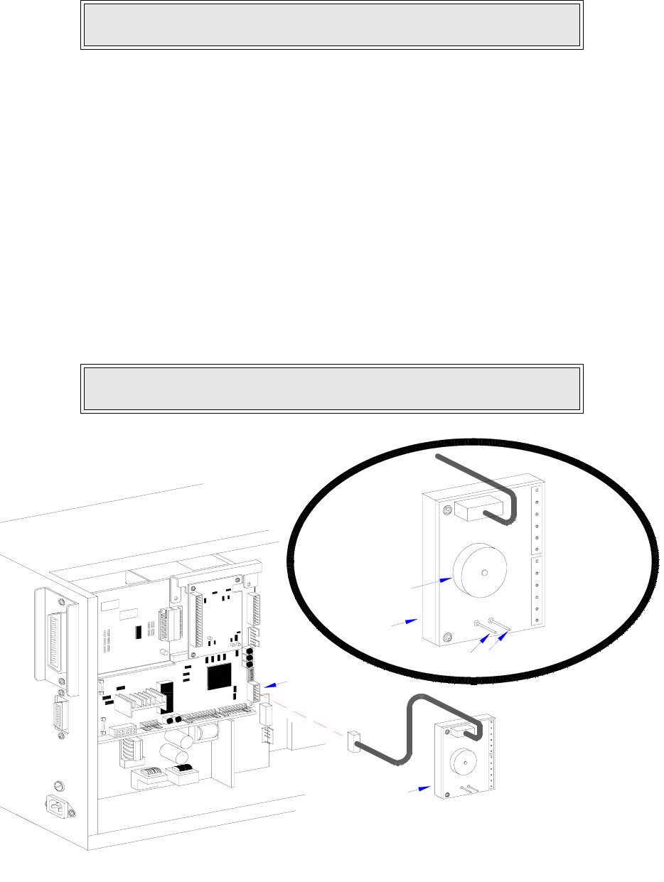
Section 8: Adjustment Procedures
M84Pro Service Manual PN 9001111A Page 8-12
4 Turn dial (3) on test module (1) to position number 5.
5 Connect the positive (+) probe of the multimeter to pin SIG (4) on test module (1).
6 Connect the negative (-) probe of the multimeter to pin GND (5) on test module (1).
7 Ensure the millimeter is set for DC voltage reading.
8 Place the label backing only in position to be read by the sensor.
9 Adjust VR4 potentiometer so that the multimeter value is less than 0.5 volts.
10 Replace the label backing with a label in position to be read by the sensor.
11 Regard the millimeter for a value of +1.0 volts more than the prior value read.
12 Repeat steps 8 through 11 until the value is +1.0 volts.
13 Test print labels to ensure proper function.
14 Disconnect test module (1) from main circuit board (2) and replace housing covers.
Figure 8-9, Label Sensor Adjustment
NOTE: Refer to TP Test Module Usage in the Troubleshooting section for
additional instruction on test module use.
NOTE: Figure 10-1 in the Diagrams & Schematics section provides guidance
on housing cover installation.
IEEE1284 + RS BOARD
01
2
8
7
6
54
3
GNDSIG
1A
2A
3A
4A
6B
5B
4B
3B
1B
2B
6A
5A
2
5A
6A
2B
1B
3B
4B
5B
6B
4A
3A
2A
1A
SIG
GND
3
4
5
6
7
8
2
1
0
1
1
3
54

Section 8: Adjustment Procedures
M84Pro Service Manual PN: 9001111A Page 8-13
EYE-MARK SENSOR ADJUSTMENT
This adjustment will require the use of a multimeter and the TP Test Module.
1 Open/remove the top, right, and left housing covers.
2 Turn the VR5 potentiometer fully counter-clockwise.
3 Connect test module (1, Figure 8-9) to main circuit board connector (2).
4 Turn dial (3) on test module (1) to position number 4.
5 Connect the positive (+) probe of the multimeter to pin SIG (4) on test module (1).
6 Connect the negative (-) probe of the multimeter to pin GND (5) on test module (1).
7 Ensure the multimeter is set for DC voltage reading.
8 Place a label without the eye-mark part in position to be read by the sensor.
9 Adjust VR4 potentiometer so that the multimeter value is less than 0.5 volts.
10 Replace the label without the eye-mark with one that has the eye-mark for sensor reading.
11 Regard the millimeter for a value of +1.0 volts more than the prior value read.
12 Repeat steps 8 through 11 until the value is +1.0 volts.
13 Test print labels to ensure proper function.
14 Disconnect test module (1) from main circuit board (2) and replace housing covers.
NOTE: Figure 10-5, Accessories & Sensors Location; Figure 10-6, Print
Position Reference Diagram; and Figures 10-7 through 10-19, Print
Operation Sequence in the Diagram & Schematics Section provide additional
instruction.
NOTE: Figure 10-1 in the Diagrams & Schematics section provides guidance
on housing cover removal.
NOTE: Refer to TP Test Module Usage in the Troubleshooting section for
additional instruction on test module use.
NOTE: Figure 10-1 in the Diagrams & Schematics section provides guidance
on housing cover installation.

Section 8: Adjustment Procedures
M84Pro Service Manual PN 9001111A Page 8-14
OFFSET LABEL STOP POSITION ADJUSTMENT
The following procedure provides for fine adjustment of the label stop position for Tear-Off,
Cutter, and Dispense Modes. The Feed/Backfeed is adjusted with the Offset potentiometer
located on the front panel. The Offset adjustment range is +/- 3.75 mm.
1 Turn the OFFSET potentiometer to the center position.
2 Press and hold the FEED key while switching on the printer.
3 When the printer beeps, release the FEED key.
4 Press the FEED key to advance to the next screen.
5 Press the LINE key to advance the counter to the desired setting.
6 Press the FEED key to begin test printing. Press the FEED key again to stop test printing.
7 Readjust the OFFSET potentiometer as necessary until proper positioning is achieved.
LCD DISPLAY ADJUSTMENT
This procedure allows illumination intensity adjustment of the LCD display. Adjustment is
performed by use of the DISPLAY potentiometer located on the Operator Panel of the front
housing cover.
1 Turn on the printer.
2 Confirm that the LCD is illuminated and a message is displayed.
3 Adjust the DISPLAY potentiometer as necessary achieved the desired setting.
NOTE: Figure 10-5, Accessories & Sensors Location; Figure 10-6, Print
Position Reference Diagram; and Figures 10-7 through 10-19, Print
Operation Sequence in the Diagram & Schematics Section provide additional
instruction.
NOTE: Only the stop position is changed with the Offset potentiometer. The
print position is changed using the Pitch potentiometer.
NOTE: The Offset potentiometer is located on the Operator Panel of the front
housing cover.
LCD DISPLAY: INITIALIZING ROM V00.00.00.00
LCD DISPLAY: TEST PRINT MODE
CONFIGURATION
LCD DISPLAY: TEST PRINT SIZE
10CM

Section 8: Adjustment Procedures
M84Pro Service Manual PN: 9001111A Page 8-15
PRINT DARKNESS ADJUSTMENT
Print darkness is adjusted by use of the PRINT potentiometer located on the Operator Panel of
the front housing cover.
1 Turn the PRINT potentiometer to the center position.
2 Turn on the printeries press the LINE key to go off-line.
3 Press the LINE and FEED keys simultaneously.
4 Press the LINE key to advance the cursor to the desired option.
5 Press the FEED key to select the option.
6 Turn the printer off and then on again.
7 Begin printing test labels antedates the PRINT potentiometer as necessary to achieve the
desired results.
LCD DISPLAY: PRINT DARKNESS
1 2 3 4 5
NOTE: It may be necessary to repeat the procedure and selecting a different
print darkness setting from the operator panel.
Section 8: Adjustment Procedures
M84Pro Service Manual PN 9001111A Page 8-16
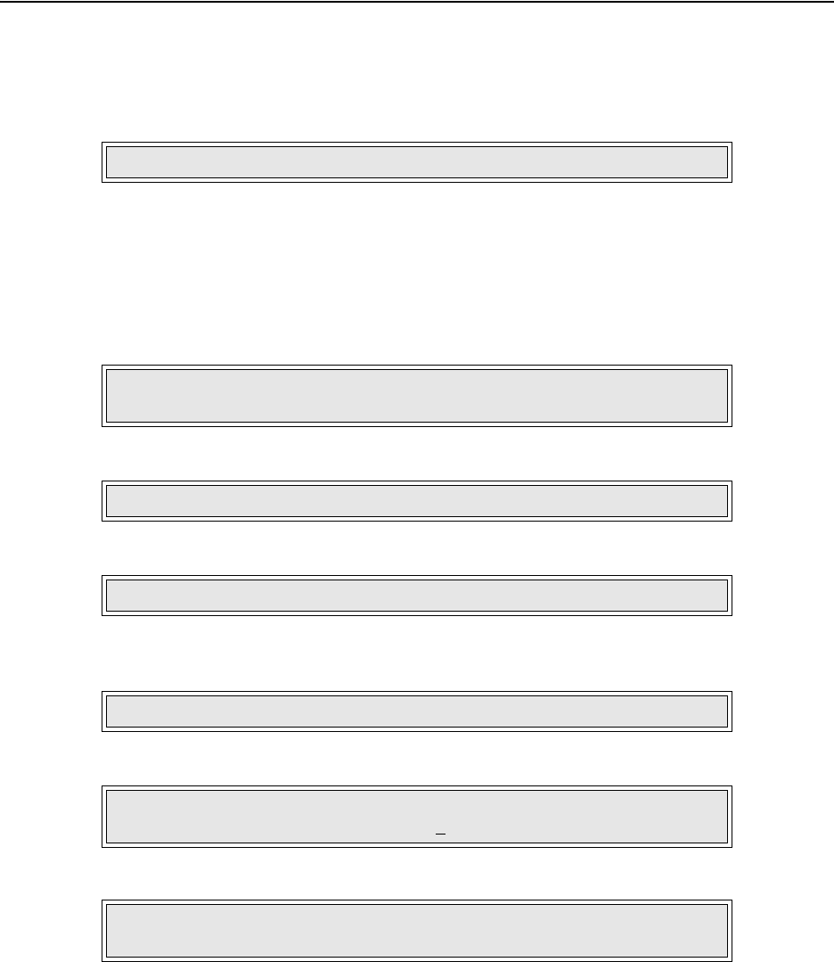
M84Pro Service Manual PN: 9001111A Page 9-1
9
FACTORY RESETS
This section of the service manual covers instructions on how to return the printer to its factory
settings. The instructions are separated into differing categories of interest.
FACTORY SETTINGS / TEST PRINT
1 Record all dip switch positions.
2 Place all dip switches in the OFF position.
3 Place the DSW2-4 in the ON position.
4 Simultaneously, press and hold the LINE and FEED keys while turning on the power switch.
5 Release the LINE and FEED keys upon hearing a beep.
6 Place the DSW2-4 in the Off position.
7 Press the FEED key to display the next screen.
8 Press the LINE key once to change the message from NONE to ALL.
9 Press the FEED key to clear the EEPROM.
10 Select the print label size by pressing the LINE key.
CAUTION: RESETTING THE PRINTER WILL CLEAR ALL REGISTERS.
LCD DISPLAY: INITIALIZING ROM V00.00.00.00
MAINTENANCE MODE DIPSW2-4 ON->OFF
LCD DISPLAY: FACTORY MODE
LCD DISPLAY: COUNTER CLEAR - NONE
LCD DISPLAY: COUNTER CLEAR - ALL
LCD DISPLAY: PRINT SIZE
SMALL LARGE
NOTE: The default selection is large. The LINE key allows scrolling from one
option to another.

Section 9: Factory Resets
M84Pro Service Manual PN: 9001111A Page 9-2
11 Press the FEED key to test print. Press the FEED key again to stop printing.
12 Verify that the counters on the test print have reset to 0.0 km.
13 Power Off the printer and confirm that all switches are in the Off or down position.
CLEAR HEAD COUNTERS
1 Record all dip switch positions.
2 Place all dip switches in the Off position.
3 Place the DSW2-4 switch in the On or up position.
4 Simultaneously, press and hold the LINE and FEED keys while turning on the power switch.
5 Release the LINE and FEED keys upon hearing a beep.
6 Place the DSW2-4 in the Off position.
7 Press the FEED key to display the next screen.
8 Press the LINE key twice to change the message from NONE to HEAD.
9 Press the FEED key to clear the head counter.
10 Select the print label size by pressing the LINE key.
WARNING: THIS TEST ACTIVATES ALL THE HEATING ELEMENTS ON
THE PRINT HEAD AND THEREFORE SHOULD BE USED FOR TESTING
PURPOSES ONLY. FULL WIDTH LABELS MUST BE USED TO PREVENT
PRINT HEAD DAMAGE.
CAUTION: RESETTING THE PRINTER WILL CLEAR ALL REGISTERS.
LCD DISPLAY: INITIALIZING ROM V00.00.00.00
MAINTENANCE MODE DIPSW2-4 ON->OFF
LCD DISPLAY: FACTORY MODE
LCD DISPLAY: COUNTER CLEAR - NONE
LCD DISPLAY: COUNTER CLEAR - HEAD
LCD DISPLAY: PRINT SIZE -
SMALL LARGE

Section 9: Factory Resets
M84Pro Service Manual PN 9001111A Page 9-3
11 Press the FEED key to test print. Press the FEED key again to stop printing.
12 Verify that the counters on the test print have reset to 0.0 km.
13 Power Off the printer and confirm that all switches are in the Off or down position.
CLEAR DISPENSER COUNTER
1 Record all dip switch positions.
2 Place all dip switches in the OFF position.
3 Place the DSW2-4 in the ON position.
4 Simultaneously, press and hold the LINE and FEED keys while turning on the power switch.
5 Release the LINE and FEED keys upon hearing a beep.
6 Place the DSW2-4 in the Off position.
7 Press the FEED key to display the next screen.
8 Press the LINE key twice to change the message from NONE to DIS.
9 Press the FEED key to clear the dispenser counter.
10 Select the print label size by pressing the LINE key.
11 Press the FEED key to test print. Press the FEED key again to stop printing.
WARNING: THIS TEST ACTIVATES ALL THE HEATING ELEMENTS ON
THE PRINT HEAD AND THEREFORE SHOULD BE USED FOR TESTING
PURPOSES ONLY. FULL WIDTH LABELS MUST BE USED TO PREVENT
PRINT HEAD DAMAGE.
CAUTION: RESETTING THE PRINTER WILL CLEAR ALL REGISTERS.
LCD DISPLAY: INITIALIZING ROM V00.00.00.00
MAINTENANCE MODE DIPSW2-4 ON->OFF
LCD DISPLAY: FACTORY MODE
LCD DISPLAY: COUNTER CLEAR - NONE
LCD DISPLAY: COUNTER CLEAR - DIS
LCD DISPLAY: PRINT SIZE
SMALL LARGE
NOTE: The default selection is large. The LINE key allows scrolling from one
option to another.

Section 9: Factory Resets
M84Pro Service Manual PN: 9001111A Page 9-4
12 Verify that the counters on the test print have reset to 0.0 km.
13 Power Off the printer and confirm that all switches are in the Off or down position.
CLEAR CUTTER COUNTER
1 Record all dip switch positions.
2 Place all dip switches in the OFF position.
3 Place the DSW2-4 in the ON position.
4 Simultaneously, press and hold the LINE and FEED keys while turning on the power switch.
5 Release the LINE and FEED keys upon hearing a beep.
6 Place the DSW2-4 in the Off position.
7 Press the FEED key to display the next screen.
8 Press the LINE key twice to change the message from NONE to CUT.
9 Press the FEED key to clear the cutter counter.
10 Select the print label size by pressing the LINE key.
11 Press the FEED key to test print. Press the FEED key again to stop printing.
WARNING: THIS TEST ACTIVATES ALL THE HEATING ELEMENTS ON
THE PRINT HEAD AND THEREFORE SHOULD BE USED FOR TESTING
PURPOSES ONLY. FULL WIDTH LABELS MUST BE USED TO PREVENT
PRINT HEAD DAMAGE.
CAUTION: RESETTING THE PRINTER WILL CLEAR ALL REGISTERS.
LCD DISPLAY: INITIALIZING ROM V00.00.00.00
MAINTENANCE MODE DIPSW2-4 ON->OFF
LCD DISPLAY: FACTORY MODE
LCD DISPLAY: COUNTER CLEAR - NONE
LCD DISPLAY: COUNTER CLEAR - CUT
LCD DISPLAY: PRINT SIZE
SMALL LARGE
NOTE: The default selection is large. The LINE key allows scrolling from one
option to another.

Section 9: Factory Resets
M84Pro Service Manual PN 9001111A Page 9-5
12 Verify that the counters on the test print have reset to 0.0 km.
13 Power Off the printer and confirm that all switches are in the Off or down position.
CLEAR EEPROM
1 Record all dip switch positions.
2 Place all dip switches in the OFF position.
3 Place the DSW2-4 in the ON position.
4 Simultaneously, press and hold the LINE and FEED keys while turning on the power switch.
5 Release the LINE and FEED keys upon hearing a beep.
6 Place the DSW2-4 in the Off position.
7 Press the LINE key to display the next screen.
8 Press the FEED key once to display the next screen.
9 Press the FEED key once to display the next screen.
10 Press the LINE key to scroll to YES.
11 Press the FEED key to clear the EEPROM.
12 Power Off the printer and confirm that all switches are in the Off or down position.
WARNING: THIS TEST ACTIVATES ALL THE HEATING ELEMENTS ON
THE PRINT HEAD AND THEREFORE SHOULD BE USED FOR TESTING
PURPOSES ONLY. FULL WIDTH LABELS MUST BE USED TO PREVENT
PRINT HEAD DAMAGE.
CAUTION: RESETTING THE PRINTER WILL CLEAR ALL REGISTERS.
LCD DISPLAY: INITIALIZING ROM V00.00.00.00
MAINTENANCE MODE DIPSW2-4 ON->OFF
LCD DISPLAY: FACTORY MODE
LCD DISPLAY: ALL CLEAR MODE
LCD DISPLAY: ALL CLEAR COUNTER
EEPROM
LCD DISPLAY: COUNTER ALL CLEAR
YES NO
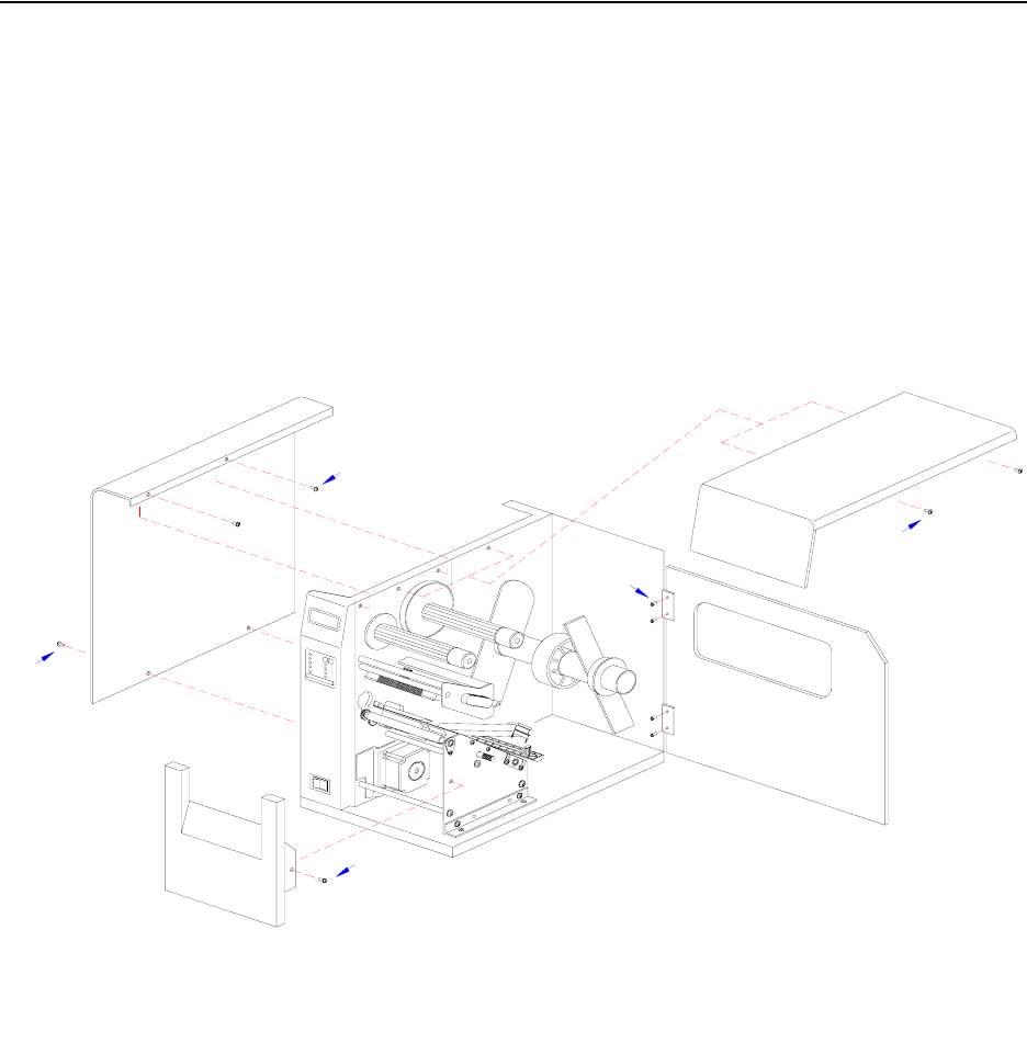
M84Pro Service Manual PN: 9001111A Page 10-1
10
DIAGRAMS & SCHEMATICS
HOUSING COVER REMOVAL & INSTALLATION
Figure, 10-1, Housing Cover Removal & Installation
Screws x2
Screws x2
Screws x2
Screws x4
Screws x1
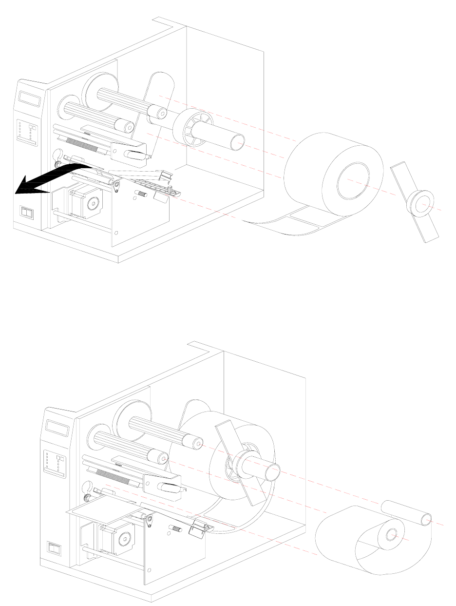
Section 10: Diagrams & Schematics
M84Pro Service Manual PN: 9001111A Page 10-2
MEDIA LOADING
Figure 10-2, Media Loading
RIBBON LOADING
Figure 10-3, Ribbon Loading
MEDIA
MEDIA
MEDIA
MEDIA
MEDIA
RIBBON
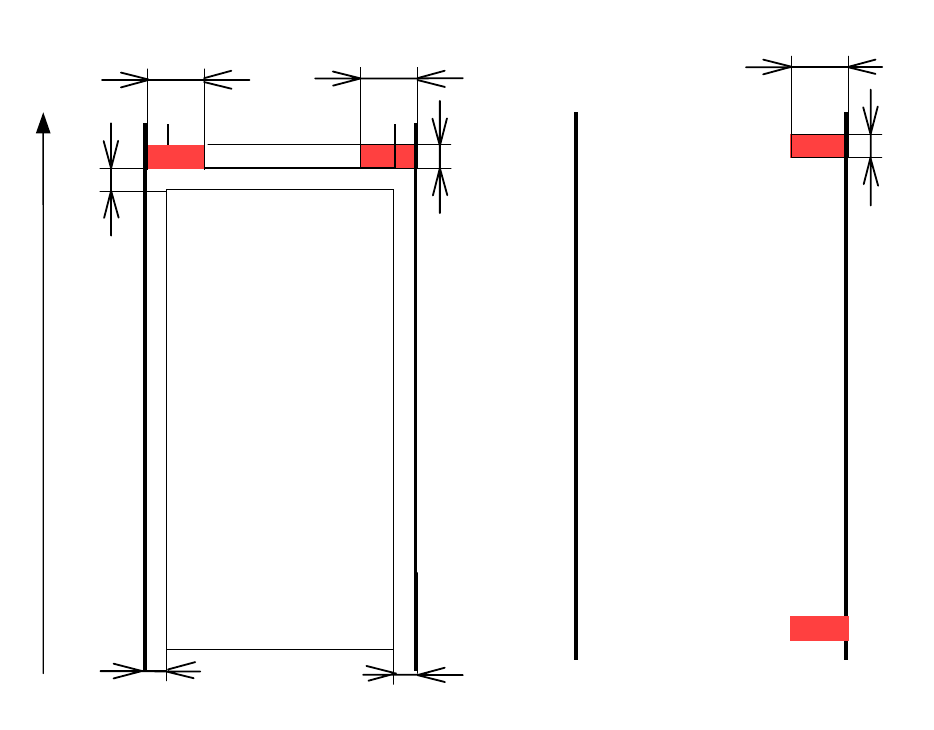
Section 10: Diagrams & Schematics
M84Pro Service Manual PN 9001111A Page 10-3
PAPER SPECIFICATIONS
Figure 10-4, Paper Specifications
3mm
3mm
14mm
1.5mm
La b el Tick et
Paper Feedin g Direction
3mm
14mm
14mm
1.5mm
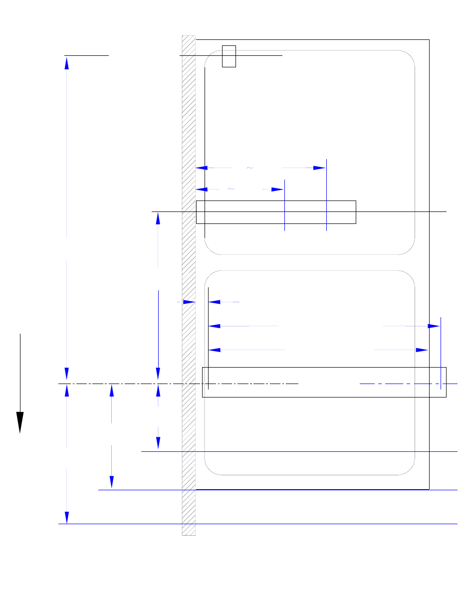
Section 10: Diagrams & Schematics
M84Pro Service Manual PN: 9001111A Page 10-4
ACCESSORIES & SENSORS LOCATION
Figure 10-5, Accessories & Sensors Location Diagram
Cutter
Tear-Off
Dispenser
Thermal Head
Head Width (112 mm)
Printable Width (104 mm)
Unprintable Area (3.2 mm)
Gap
Eye-Mark
Gap/Eye-Mark
Paper End Switch
11.5 mm
16.0 mm
19.5 mm
49.5 mm
97.0 mm
6
17
54 mm
65 mm
PAPER FEED DIRECTION
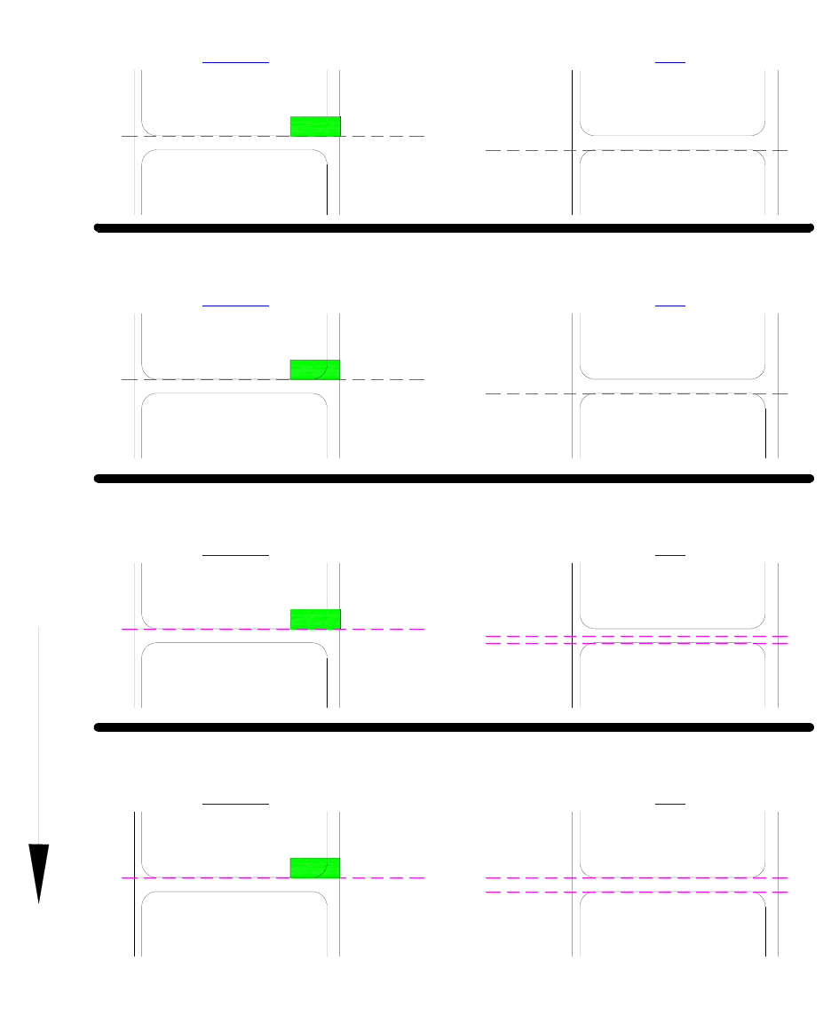
Section 10: Diagrams & Schematics
M84Pro Service Manual PN 9001111A Page 10-5
PRINT POSITION REFERENCE DIAGRAM
Figure 10-6, Print Position Reference Diagram
GAP
PAPER FEED DIRECTION
EYE-MARK
LABEL
LABEL LABEL
LABEL
Base Reference
Print Position Base Reference
Print Position
CONTINUOUS PRINTING
TEAR-OFF MODE
Print Position
Base Reference
LABEL
LABEL
LABEL
LABEL
EYE-MARK GAP
Tear-Off Position
Tear-Off Position
Base Reference
Print Position
Print Position
Base Reference
Cut Position
Cut Position
GAP
EYE-MARK
LABEL
LABEL LABEL
LABEL
Base Reference
Print Position
CUTTER MODE
PEEL-OFF MODE
Print Position
Base Reference
LABEL
LABEL
LABEL
LABEL
EYE-MARK GAP
Peel-Off Position Peel-Off Position
Base Reference
Print Position
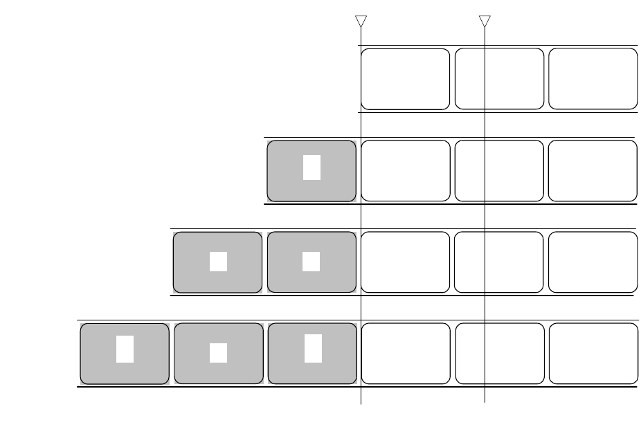
Section 10: Diagrams & Schematics
M84Pro Service Manual PN: 9001111A Page 10-6
PRINT OPERATION SEQUENCE
CONTINUOUS, PITCH SENSOR ENABLED (HEAD CHECK DISABLED)
Figure 10-7, Operation Sequence Chart
c d e
Head Pitch sensor (gap)
cde f
Print 1st page
Standby
c d ef g
c def g h
Print 2nd page
Print 3rd page
(Note)
Above is the base reference position when the gap sensor is used.
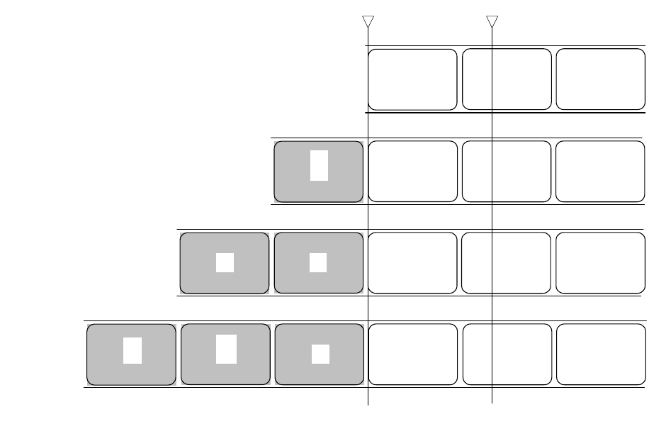
Section 10: Diagrams & Schematics
M84Pro Service Manual PN 9001111A Page 10-7
CONTINUOUS, PITCH SENSOR DISABLED (HEAD CHECK DISABLED)
Figure 10-8, Operation Sequence Chart
c d e
Head Pitch sensor
(g
a
p)
cde f
Print 1st page
+head check
Standby
c d e f g
c d e f g h
Print 2nd page
+head check
Print 3rd page
+head check
(Note)
Above is the base reference
p
osition when the
g
a
p
sensor is used.
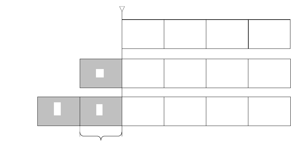
Section 10: Diagrams & Schematics
M84Pro Service Manual PN: 9001111A Page 10-8
CONTINUOUS, PITCH SENSOR DISABLED (HEAD CHECK ENABLED)
Figure 10-9, Operation Sequence Chart
After print operation
Before print operation
c d e f
c
d
efg
Paper is transported actual print size portion in vertical direction.
However, if the <EP> command is specified, the paper is transported at the specified vertical paper size portion.
Head
cd e f
g
h
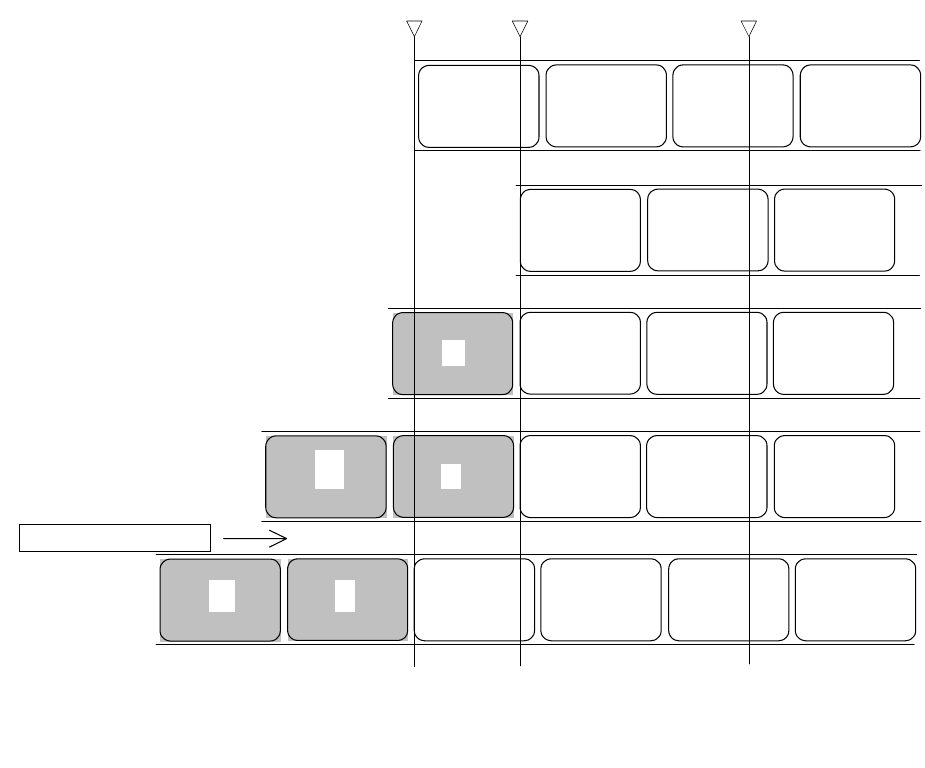
Section 10: Diagrams & Schematics
M84Pro Service Manual PN 9001111A Page 10-9
TEAR-OFF, PITCH SENSOR ENABLED (HEAD CHECK DISABLED)
Figure 10-10, Operation Sequence Chart
c d e
Manual cut Pitch senso
r
(g
a
p)
c
d
e
Backfeed
up to base reference print
p
osition
Standby
c d e
f
c
d
efg
Print 1st page
Print 2nd
p
a
g
e
Head
f
c
d
e f g h
Feed to manual cu
t
p
osition
500 msec passes
(Note)
After printing, if there is no following print data after 500 msec passes, feeds to manual cut position
Above is the base reference position when the gap sensor is used.
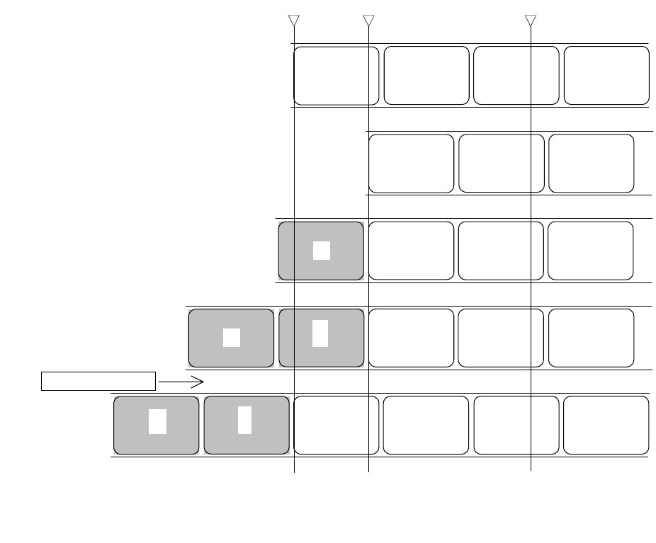
Section 10: Diagrams & Schematics
M84Pro Service Manual PN: 9001111A Page 10-10
TEAR-OFF, PITCH SENSOR ENABLED (HEAD CHECK ENABLED)
Figure 10-11, Operation Sequence Chart
Manual cut Pitch sensor
(g
a
p)
cd
e
Back feed
up to base reference print position
Standby
c d e f
cde f g
Print 1st page
Print 2nd
p
a
g
e
Head
c d e
f
c
d
e
f
g h
Feed to manual cu
t
p
osition
500 msec passes
(Note)
After printing, if there is no following print data after 500 msec passes, feeds to manual cut position
Above is the base reference position when the gap sensor is used.
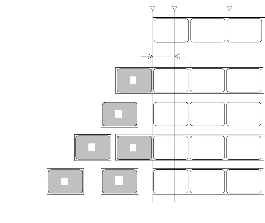
Section 10: Diagrams & Schematics
M84Pro Service Manual PN 9001111A Page 10-11
CUTTER, NO BACKFEED
Figure 10-12, Operation Sequence Chart
c
Cut Pitch sensor (gap)
c d e
Print 1st page
Standby
d e f
Cutter operation
Print 2nd
p
a
g
e
Head
* 1: Because back feed operation is not performed, an unprintable area occurs at the front.
(Note)
Above is the base reference print position when the gap sensor is used.
c
N
ote 1: Unprintable area
d e f
e f g
d
e f g
d
c
c
Cutter operation
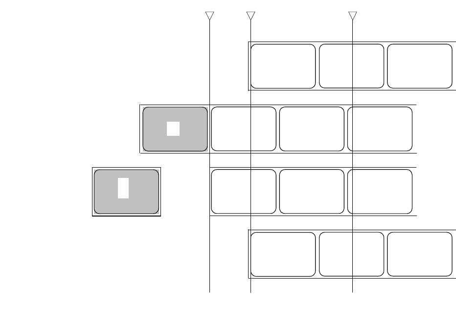
Section 10: Diagrams & Schematics
M84Pro Service Manual PN: 9001111A Page 10-12
CUTTER, OPERATION 1
Figure 10-13, Operation Sequence Chart
Cut Pitch sensor
(g
a
p)
cd e
Print 1st page
Standby
Cutter operation
Back feed
Head
d e f
c
d
ef
c
d e f
(Note)
Above is the base reference position when the gap sensor is used.
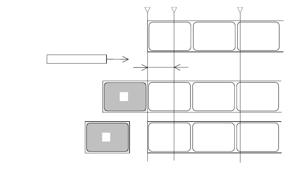
Section 10: Diagrams & Schematics
M84Pro Service Manual PN 9001111A Page 10-13
CUTTER, NO BACKFEED, EXTERNAL PULSE INPUT
Figure 10-14, Operation Sequence Chart
Cut Pitch sensor (gap)
c d e
Print 1st page
Standby
d e f
Cutter operation
Head
N
ote 1: Because backfeed operation is not performed, an unprintable area occurs at the front.
(Note)
Above is the base reference print position when the gap sensor is used.
c
N
ote 1: Unprintable area
def
c
Print si
g
nal in
p
ut
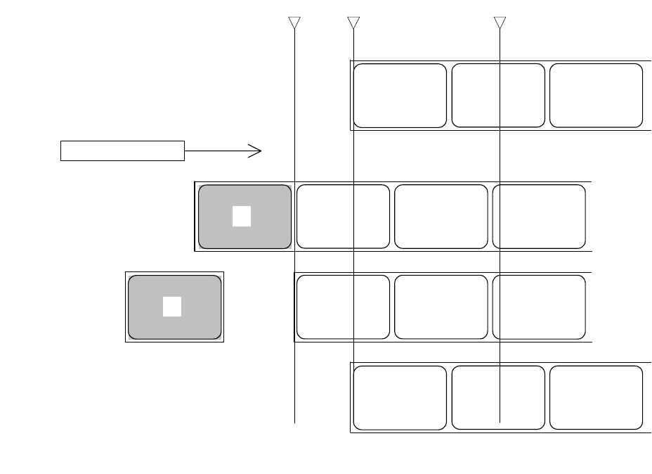
Section 10: Diagrams & Schematics
M84Pro Service Manual PN: 9001111A Page 10-14
CUTTER, OPERATION 1, EXTERNAL PULSE INPUT
Figure 10-15, Operation Sequence Chart
Cut Pitch sensor
(g
a
p)
c d e
Print 1st page
Standby
Cutter operation
Backfeed
Head
d e f
c
d e f
c
d e f
Print signal input
(Note)
Above is the base reference
p
osition when the
g
a
p
sensor is used.
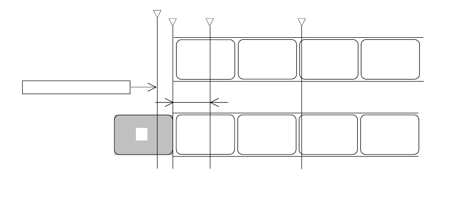
Section 10: Diagrams & Schematics
M84Pro Service Manual PN 9001111A Page 10-15
PEEL-OFF, PEEL-OFF SENSOR, NO BACKFEED
Figure 10-16, Operation Sequence Chart
Peel-off Pitch sensor
(g
a
p)
Print 1st page
Standby
Head
d e f
c
d e fc g
Note 1: Peel-off senor check
N
ote 2: Unprintable area
Peel-off senso
r
N
ote 1: The peel-off sensor checks the peel-off status of the label, and does not move to the next operation until the label
is peeled.
N
ote 2: Because backfeed operation is not performed, an unprintable area occurs at the front.
(Note)
Above is the base reference position when the gap sensor is used.
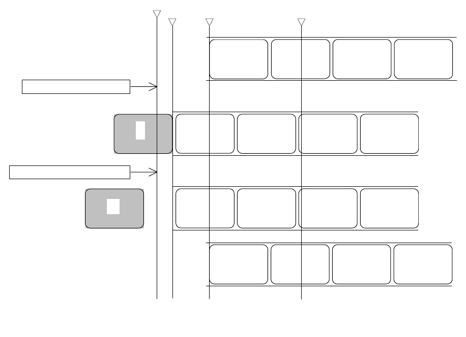
Section 10: Diagrams & Schematics
M84Pro Service Manual PN: 9001111A Page 10-16
PEEL-OFF, PEEL-OFF SENSOR, OPERATION 1
Figure 10-17, Operation Sequence Chart
Peel-off Pitch sensor (gap)
Print 1st page
Standby
Head
d e f
c
d e f
c
g
Note 1: Peel-off sensor check
Peel-off sensor
Note 1: The peel-off sensor checks the peel-off status of the label, and does not move to the next operation until the label i
s
peeled.
(Note)
Above is the base reference position when the
g
ap sensor is used.
Note 1: Peel-off sensor check
Label peel-off d e f
c g
d e f g
Backfeed
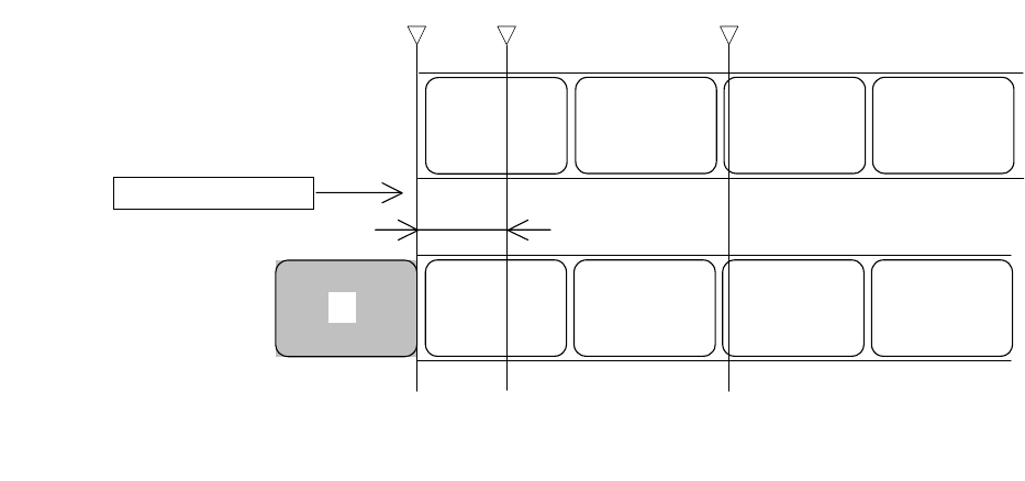
Section 10: Diagrams & Schematics
M84Pro Service Manual PN 9001111A Page 10-17
PEEL-OFF, EXTERNAL PULSE INPUT, NO BACKFEED
Figure 10-18, Operation Sequence Chart
Peel-off Pitch sensor
(g
a
p)
Print 1st page
Standby
Head
d e f
c
de fc
g
Print signal input
N
ote 1: Unprintable area
N
ote 1: Because backfeed operation is not performed, an unprintable area occurs at the front.
(Note)
Above is the base reference position when the gap sensor is used.
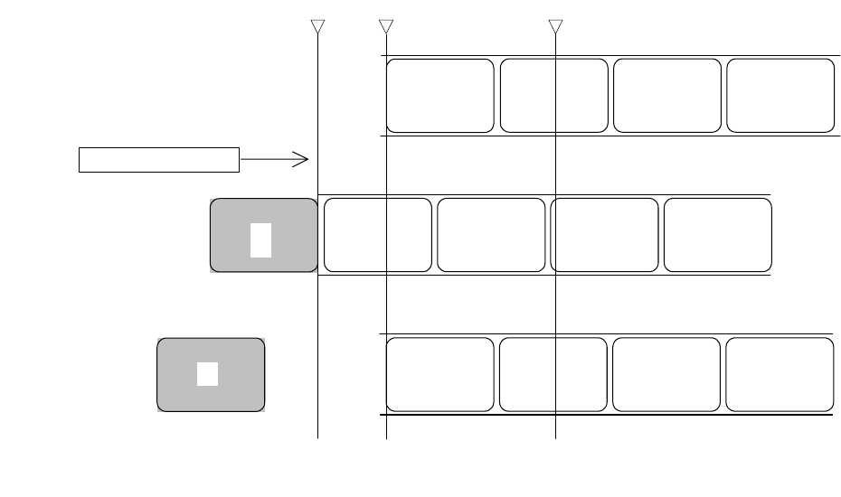
Section 10: Diagrams & Schematics
M84Pro Service Manual PN: 9001111A Page 10-18
PEEL-OFF, EXTERNAL PULSE INPUT, OPERATION 1
Figure 10-19, Operation Sequence Chart
Peel-off Pitch sensor
(g
a
p)
Print 1st page
Standby
Head
d
e
fc
def
c g
Print signal input
Backfeed c d e f g
(Note)
Above is the base reference position when the gap sensor is used.
