User manual

Savari S-50 Operations,
Administration, Maintenance
& Provisioning
(OAM&P) Guide for Transcore
Application
2005 De La Cruz Boulevard #131,
Santa Clara, CA 95050
Document Version: 0.4
Release: SW 2.0.4
Date: 5th Feb, 2015
Savari S-50 Operations, Administration, Maintenance & Provisioning Guide
Savari Inc., Confidential
Copyright © Savari, Inc, 2014
2
Copyright © Savari, Inc., 2014. All Rights Reserved. This publication, in whole or in part, may
not be reproduced, stored in a computerized, or other retrieval System or transmitted in any
form, or by any means whatsoever without the prior written permission from Savari, Inc.
Version Information
S.No
Document Version
Date
Reason for Change
1
0.1
Dec 8, 2014
Initial Version
2
0.2
Jan 20, 2015
Corrections based on
internal review
3.
0.3
Jan 22, 2015
Added LED Table and
FCC info.
4.
0.4
Feb 5, 2015
Added FCC Para

Savari S-50 Operations, Administration, Maintenance & Provisioning Guide
Savari Inc., Confidential
Copyright © Savari, Inc, 2014
3
Table of Contents
!!"#$%&'()$"&# ******************************************************************************************************************************************************** +!
,!-..%/0"-$"******************************************************************************************************************************************************* 2!
3!1-0-%"412546/-$(%/1 ******************************************************************************************************************************************* 7!
!"#!$%&'( """""""""""""""""""""""""""""""""""""""""""""""""""""""""""""""""""""""""""""""""""""""""""""""""""""""""""""""""""""""""""""""""""""""""""""""""""""""""""""""""""""""""""""""""""""""""""")!
!"*!'+,-.%/&.'+,)./012($3'/4 """"""""""""""""""""""""""""""""""""""""""""""""""""""""""""""""""""""""""""""""""""""""""""""""""""""""""""""""""""""""""""""""""""""""""""""""")!
!"!!1$%/56($0.%++7'6%1'(/""""""""""""""""""""""""""""""""""""""""""""""""""""""""""""""""""""""""""""""""""""""""""""""""""""""""""""""""""""""""""""""""""""""""""""""""""""""""")!
3.3.1!Transcore,Application .......................................................................................................................................................6!
3.3.2!LED,Behavior.........................................................................................................................................................................7!
+!8-%'9-%/4)&:;&#/#$1 *********************************************************************************************************************************!5!
-"#!+(20$""""""""""""""""""""""""""""""""""""""""""""""""""""""""""""""""""""""""""""""""""""""""""""""""""""""""""""""""""""""""""""""""""""""""""""""""""""""""""""""""""""""""""""""""""""""""#8!
-"*!&5$6.9":.4;<.$%&'( """"""""""""""""""""""""""""""""""""""""""""""""""""""""""""""""""""""""""""""""""""""""""""""""""""""""""""""""""""""""""""""""""""""""""""""""""""""""""""#8!
-"!!2'$07055.*"-.4;<.$%&'(""""""""""""""""""""""""""""""""""""""""""""""""""""""""""""""""""""""""""""""""""""""""""""""""""""""""""""""""""""""""""""""""""""""""""""""""""""" #8!
-"-!51($%40 """"""""""""""""""""""""""""""""""""""""""""""""""""""""""""""""""""""""""""""""""""""""""""""""""""""""""""""""""""""""""""""""""""""""""""""""""""""""""""""""""""""""""""""""""""##!
-"9!70&5"""""""""""""""""""""""""""""""""""""""""""""""""""""""""""""""""""""""""""""""""""""""""""""""""""""""""""""""""""""""""""""""""""""""""""""""""""""""""""""""""""""""""""""""""""""""""""##!
-")!='/'>?5@.A01;0$/01B"""""""""""""""""""""""""""""""""""""""""""""""""""""""""""""""""""""""""""""""""""""""""""""""""""""""""""""""""""""""""""""""""""""""""""""""""""""""""##!
-"C!D66 """""""""""""""""""""""""""""""""""""""""""""""""""""""""""""""""""""""""""""""""""""""""""""""""""""""""""""""""""""""""""""""""""""""""""""""""""""""""""""""""""""""""""""""""""""""""""""##!
2!1<254=/$$"#=41$-%$/'***************************************************************************************************************************************!,!
9"#!4011'/4.51%$10&.?5'/4.1;0.67' """"""""""""""""""""""""""""""""""""""""""""""""""""""""""""""""""""""""""""""""""""""""""""""""""""""""""""""""""""""""""""""""""""""#*!
5.1.1!Default,Configuration,(CLI) ......................................................................................................................................... 12!
9"*!,'5?%7.51%1?5.'/&'6%1($5""""""""""""""""""""""""""""""""""""""""""""""""""""""""""""""""""""""""""""""""""""""""""""""""""""""""""""""""""""""""""""""""""""""""""""""""""#*!
6!USING THE COMMAND LINE INTERFACE (CLI) ******************************************************************************!3!
)"#!/012($3.6(/D'4?$%1'(/ """""""""""""""""""""""""""""""""""""""""""""""""""""""""""""""""""""""""""""""""""""""""""""""""""""""""""""""""""""""""""""""""""""""""""""""""""#!!
6.1.1!IP,Address,configuration............................................................................................................................................... 13!
)"*!6;%/4'/4.1;0.+%552($& """"""""""""""""""""""""""""""""""""""""""""""""""""""""""""""""""""""""""""""""""""""""""""""""""""""""""""""""""""""""""""""""""""""""""""""""""""#!!
)"!!1$%/56($0.%++7'6%1'(/.A1$%/5%++B"""""""""""""""""""""""""""""""""""""""""""""""""""""""""""""""""""""""""""""""""""""""""""""""""""""""""""""""""""""""""""""#!!
>!6"%:9-%/4(;=%-'/4;%&)/'(%/4(1"#=4$8/4)?" ***********************************************************************************!2!
8!CLI COMMANDS *************************************************************************************************************************************************!7!
@!-;;/#'"A4-B41<254;&9/%4"#1$-??-$"&#****************************************************************************************************!>!
:"#!1$%/56($0.(@?.6%@70.&'%4$%=5 """""""""""""""""""""""""""""""""""""""""""""""""""""""""""""""""""""""""""""""""""""""""""""""""""""""""""""""""""""""""""""""""""#C!
9.1.1!InFvehicle,(Taxi),Cable ................................................................................................................................................... 17!
:"*!(@?.6%@70 """""""""""""""""""""""""""""""""""""""""""""""""""""""""""""""""""""""""""""""""""""""""""""""""""""""""""""""""""""""""""""""""""""""""""""""""""""""""""""""""""""""""""""""#E!
1 Introduction
The Savari S-50 is a purpose built On-Board Unit (OBU) for interoperability with a Transcore
LMU-TC (also known as ROVR in this document) and a Savari StreetWAVE™. The OBU
communicates with the LMU-TC and receives GPS breadcrumb information. The OBU stores
this data in persistent memory until it is able to upload it to the specific RSE. The
communication between the LMU-TC and the OBU is over aproprietary 2.4 GHz link whereas
the communication to the RSE is over a DSRC 5.9 GHz link. The S-50 OBU has been built as
a plug and play device without needing any user intervention. However, the S-50 OBU has
been equipped with a provisioning interface that can receive and load new versions of
software, new configurations and instructions to perform logging functions and download log
messages to an external device.
Figure 1: StreetWAVE™
Savari S-50 Operations, Administration, Maintenance & Provisioning Guide
Savari Inc., Confidential
Copyright © Savari, Inc, 2014
5
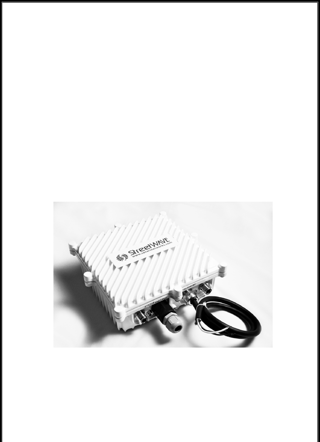
Figure 2: Savari S-50
2 Abbreviations
The following are the abbreviations used throughout this document:
Abbreviation
Expansion
DSRC
Dedicated Short Range Communication
GPS
Global Positioning System
ITS
Intelligent Transportation Systems
ITIS
International Traveler Information Systems
IP
Internet Protocol
LED
Light Emitting Diode
OBE/OBU
On-Board Equipment/On-Board Unit
PSC
Provider Service Context
RFC
Request for Comments
RSE/RSU
Roadside Equipment/Roadside Unit
RX
Receive
SSH
Secure Shell
TCP
Transmission Control Protocol
TX
Transmit
WAVE
Wireless Access in Vehicular Environments
WSA
WAVE Service Advertisement

Savari S-50 Operations, Administration, Maintenance & Provisioning Guide
Savari Inc., Confidential
Copyright © Savari, Inc, 2014
6
3 Savari S50 Features
This chapter explains the salient features of the Savari S-50 (alternatively known as OBU in
this document).
3.1 Radio
Each S-50 unit consists of two radios:
• A high-powered 5.9 GHz DSRC radio
• A 2.4 GHz radio that operates on a proprietary protocol
Both radios feature an internal antenna.
3.2 IPv4 and IPv6 Networking
Each S-50 unit consists of one Ethernet interface (eth0) and one wireless interface (ath0).
The S-50 provides support for IPv4 on its Ethernet interface and IPv6 networking on its DSRC
interface. The latter functionality is seamless to the user and does not require any
configuration. The Ethernet interface is accessed using the mini USB connector on the S-50. A
corresponding USB to Ethernet adaptor will be required. The default IPv4 address is
192.168.40.40.
3.3 Transcore Application
The specific application has two parts: A downstream communication with the LMU-TC and an
upstream communication to the Savari RSE.
3.3.1 Transcore Application
The Savari S-50 is a small form factor purpose-built DSRC OBU that is capable of 2.4G
wireless communications with a Transcore LMU-TC and receiveing GPS breadcrumb data in a
proprietary format. The S-50 resides in the taxi and is connected to vehicle power using a 2
pin custom cable. See Appendix A for details on the power connectivity.
The RSE transmits a DSRC Wave Service Advertisement (WSA) with a specific Provider
Service Context (PSC) String (defaulted to ‘tsf0’). The WSA is transmitted every 100 ms from
the RSE. The WSA message contains many parameters and instructions that are interpreted

Savari S-50 Operations, Administration, Maintenance & Provisioning Guide
Savari Inc., Confidential
Copyright © Savari, Inc, 2014
7
by all S-50s. The information within the WSA can be user configured by accessing the Savari
RSE. Among other information, the information in the WSA enables the following:
1. Transmission of an RSSI threshold – Upon receipt of the WSA, The S-50 configures its
minimum RSSI threshold value. The breadcrumbs are then uploaded only when the
measured RSSI is greater than the minimum threshold value.
2. Logging – The S-50 will enable or disable logging as per the instructions within the
WSA. It also uploads an indicated number of records to the RSE along with the
breadcrumb information. This capability will be useful for on-field debugging as it
allows the receipt of some information (although minimal) without the need for manual
intervention on the S-50. The size of the logging can also be specified within the WSA
messages.
Note: The instructions/parameters sent by WSA will be common to all S-50s in
listening distance.
Receipt of a WSA by the S-50 is an indication of the availability of an RSE that provides this
specific ‘Transcore’ Application. The WSA consists of sufficient information to differentiate and
uniquely identify this specific RSE with another generic DSRC RSE. The S-50 configures itself
with the received RSSI threshold value (received in the WSA). It then uses its own measured
RSSI value (of the RSE signal) to perform a comparison. If the received value is higher than
the configured value, the S-50 enters into a communication transaction to upload all data to
the RSE. Only S-50 units that are configured with the same PSC (as the RSE) respond.
Hence, if desired, it is possible to have multiple S-50s communicate with specific RSEs.
Multiple breadcrumbs are packed into a single DSRC packet (up to 1500 bytes). The S-50
stores a maximum of 100 breadcrumbs. The specific sequence of breadcrumbs stored is
based on an algorithm specified by Transcore. Up to 5 DSRC packets of data may be required
to transfer all stored breadcrumbs (5 DSRC packets for 100 breadcrumbs).
3.3.2 LED Behavior
The S-50 uses a dual color (red and green) LED to indicate functional status.
RED LED
After Power ON, the RED LED will be lit for roughly 10-12 seconds till the kernel boots. The
RED LED is then turned OFF. After another 7-9 seconds, the RED is lit once for 200 ms
indicating that the OBU is fully functional. If the RED LED is continuously lit for greater than 20
seconds, it is unlikely to be functioning correctly and a corrective action might be needed. Any
Savari S-50 Operations, Administration, Maintenance & Provisioning Guide
Savari Inc., Confidential
Copyright © Savari, Inc, 2014
8
intermittent blink (200 ms) of the RED LED indicates receipt of a breadcrumb/message from
the Transcore LMU-TC.
Note: The figure of 10-12 seconds and 7-9 seconds is for a rough estimate and is not meant to
be used as an exact number. In reality, the actual time may vary by a couple of seconds. The
table below for troubleshooting takes into consideration the outer boundary to provide a
definite indication of behavior.
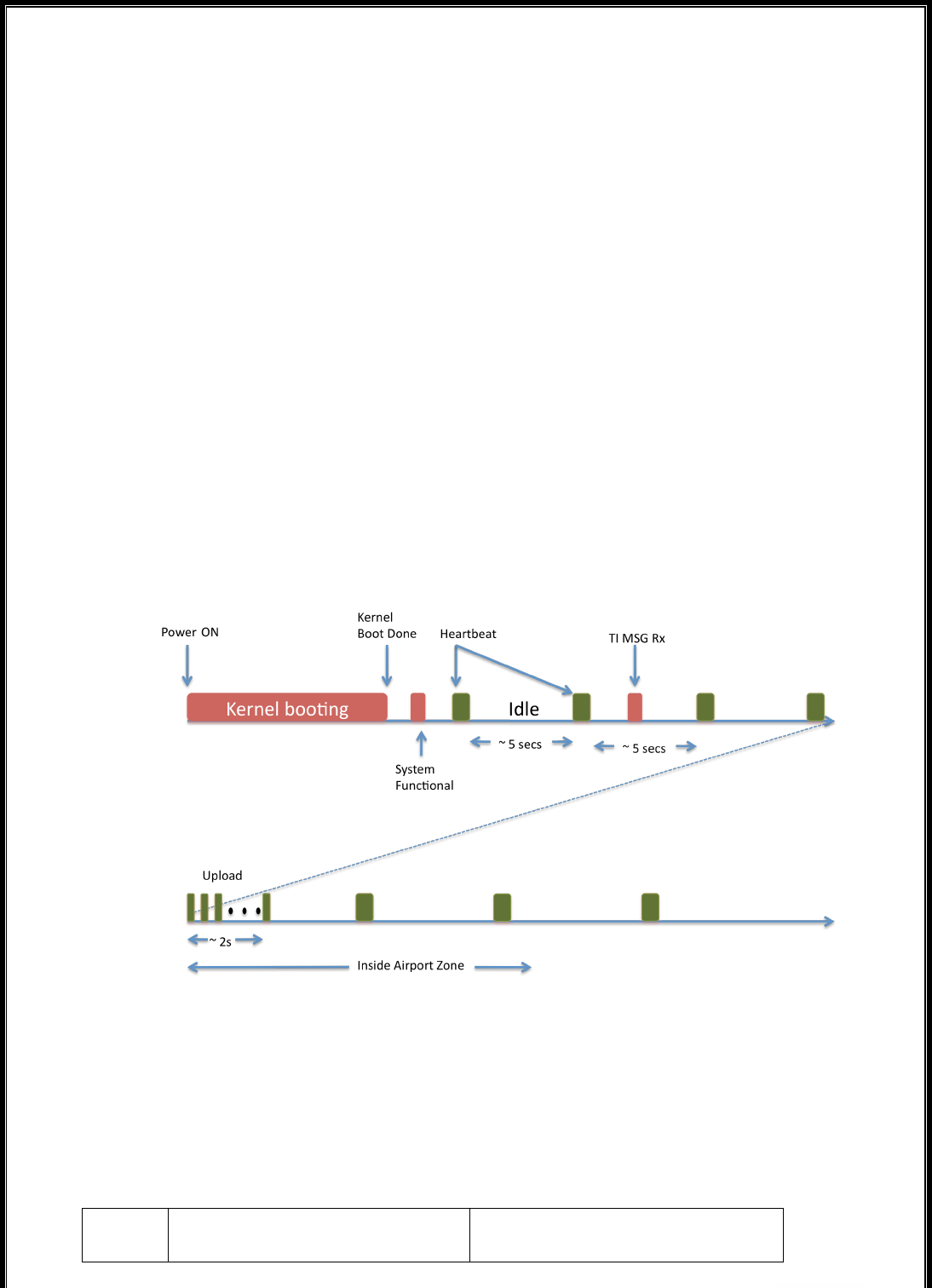
GREEN LED
After the OBU boots and is in a fully functional state, the Green LED is lit for 200 ms once
every 5 seconds (also termed as heartbeat) to indicate that the system is functioning correctly.
During an upload to the RSE the Green LED is blinked at a rate of 100 ms ON and 100 ms
OFF for a period of 2 seconds. This action is used to visually indicate a successful upload of
data from an OBE to an RSE.
Figure 3 S50 LED Sequence
LED BEHAVIOR FOR TROUBLESHOOTING
The behavior of the LEDs is described below in a tabular form.
LED
Visual Behavior
Indication

Savari S-50 Operations, Administration, Maintenance & Provisioning Guide
Savari Inc., Confidential
Copyright © Savari, Inc, 2014
9
RED
Continuously Lit for greater than
15 sec at anytime
Boot-up sequence / functionality
failed. Retry after a power cycle.
RED
Continuously Lit for up to 10 sec
Power ON boot sequence in
progress (during initial bootup).
RED
Single flash of 200ms
OBU ready (signifying successful
boot-up) OR receipt of breadcrumb
from LMU-TC (after successful
boot-up)
GREEN
Single flash of 200ms every ~5
sec
Indication of OBU in an operative
state and (only valid after boot-up
sequence is complete)
GREEN
Continuous ON/OFF for 100ms
each for 2 seconds
Indication of successful data
upload to the RSE (only valid after
boot-up sequence is complete)
GREEN
& RED
Both continuously off for > 6 sec
Device not functioning correctly.
Check power connectivity and retry
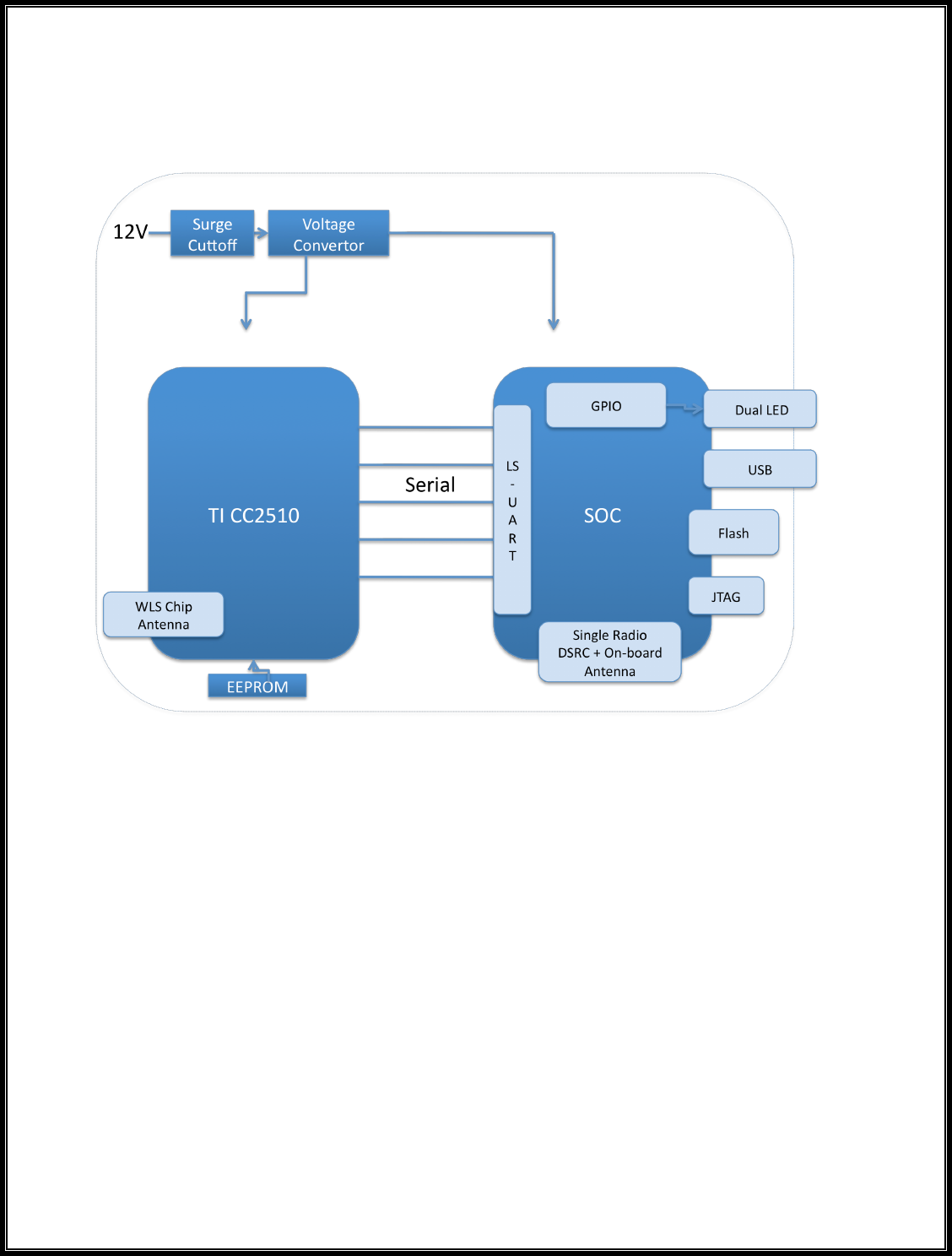
4 Hardware Components
Figure 4 S-50 HW Block Diagram
4.1 Power
The S-50 is powered by the vehicle switched battery power (see Appendix A). Surge and low
voltage cutoff is provided for within the OBE.
4.2 DSRC 5.9 GHz Radio
A single DSRC radio supports 802.11p in the hardware and uses an on-board antenna.
4.3 Wireless 2.4 GHz Radio
A single wireless 2.4 GHz radio provides the communication mechanism with the Transcore LMU-
TC. It uses an on-board antenna.

Savari S-50 Operations, Administration, Maintenance & Provisioning Guide
Savari Inc., Confidential
Copyright © Savari, Inc, 2014
11
4.4 Storage
The S-50 incorporates an on-board FLASH for storing the breadcrumbs as well as other log data.
The log data is only required in case advanced troubleshooting is required.
Note: The S-50 supports tftp utility to make it easier for retrieving the log data to an external
platform for off-board analysis.
4.5 LEDs
S-50 unit is installed with a dual LED on the enclosure to indicate power and device operation
state.
4.6 Mini-USB (Ethernet)
S-50 consists of one Ethernet port (eth0) but accessed via the mini USB port.
4.7 FCC
FCC ID: OUP020300101, Please refer to FCC Part 95

5 S-50 Getting Started
This section describes the procedures to get the S-50 started after installation and power up.
5.1 Getting Started Using the CLI
This section describes the procedures to get the S-50 started using the CLI.
To Access using Telnet
telnet <Default/Configured IP Address>
The default IP address is 192.168.40.40
Password: As given in the Default Configuration (CLI) section.
5.1.1 Default Configuration (CLI)
The S-50 has the following default configuration:
Username: root
Password: 5up
Ethernet (eth0)
IPv4 Address: 192.168.40.40 (if using default)
5.2 Visual Status Indicators
See “LED Behavior” (Sec 3.3.2) for more details.

6 Using the Command Line Interface (CLI)
This chapter describes the operations that you can perform using S-50 CLI commands. The S-50
comes pre-configured as described in the Default Configuration (CLI) section..
Caution: Only advanced users should use the instructions given below. Incorrect
modification of the following parameters may make the S-50 inoperable or inaccessible.
Note: All configuration changes will only be applied once the device is power rebooted.
6.1 Network configuration
6.1.1 IP Address configuration
The IP address of the USB-Ethernet interface is factory set to 192.168.40.40. The IP address can
be changed if needed by the following command
1. #cfg –a USB2ETH_IPADDR=a.b.c.d
2. #cfg –c
3. Power cycle the OBU
The change is not persistent across FW upgrades.
6.2 Changing the Password
The password for the ‘root’ user can be changed using the following command.
1. #passwd root
2. When prompted, provide the new password.
The change is not persistent across FW upgrades.
6.3 Transcore Application (TransApp)

Savari S-50 Operations, Administration, Maintenance & Provisioning Guide
Savari Inc., Confidential
Copyright © Savari, Inc, 2014
14
The S-50 has been designed to be a plug and play device. It is recommended that the CLI be
used for any required operations, administration, maintenance and provisioning by an advanced
user only.
The S-50 TransApp application requires the ‘obe_conf’ configuration file located at
/tmp/rw/obe_conf.
Parameter
Value
Range
Description
ProviderServiceContext
tsf0
Some unique string.
Provider service
context. This string
needs to match the PSC
string on the RSE.
Default: tsf0
logfilesize
5000
5 KB to 10
KB
Size of the log file on
the OBE in Bytes.
Default: 5 KB
maxretry
5
1 to 10
Maximum retry from
OBE to RSE. Do not
modify, this is a test only
parameter
retry_mechanism
0
0 or 1
type of retry
mechanism. Do not
modify, this is a test only
parameter

Savari S-50 Operations, Administration, Maintenance & Provisioning Guide
Savari Inc., Confidential
Copyright © Savari, Inc, 2014
15
uplobelog
0
0 to 10
Upload number of
records of the OBE log
set by the RSE WSA
message.
0 indicates that upload
is disabled
0 < value < 11 indicates
the number of records to
upload.
The above parameter changes will take effect after a power cycle of the OBE.
7 Firmware Upgrade Procedure Using the CLI
The following is the procedure to upgrade the OBE firmware using the CLI:
1. Connect a local PC to the S-50 via Ethernet to mini-USB adaptor.
2. Assign the IP address to the PC to be in the same subnet of the S-50, preferably
192.168.40.1.
3. Download the image to be upgraded from the Savari FTP site to the PC.
4. Copy the image to the tftp server directory of the PC. Image should be names as
“Timage.tgz”. Ensure that the tftp server is running on the PC.
5. Login to the OBE using telnet and issue the following commands
6. #cfg –a TFTP_SERVER=192.168.40.1
7. #cfg –c
8. #/etc/upgrade.sh
9. Power cycle the OBU when the upgrade process has completed (an “upgrade done”
message is displayed).
Savari S-50 Operations, Administration, Maintenance & Provisioning Guide
Savari Inc., Confidential
Copyright © Savari, Inc, 2014
16
8 CLI Commands
The S-50 OS is based on the Linux Operating System (OS). All well-known Linux commands are
supported.
The following are the key commands and their descriptions:
Command
Description
reboot
This command reboots the device.
passwd
#passwd root
This command allows the user to change the password.
Executing the command will
ifconfig
To view and modify the interface status (UP/DOWN) and IP
address configuration without changing the persistent
configuration.
9 Appendix A: S-50 Power Installation
This chapter contains diagrams depicting the In-vehicle and OBU cables that are a part of the
Transcore OBU setup. The OBU will ship with a two-conductor, one-foot length cable terminated
by a Molex connector (details below).
9.1 Transcore OBU Cable Diagrams
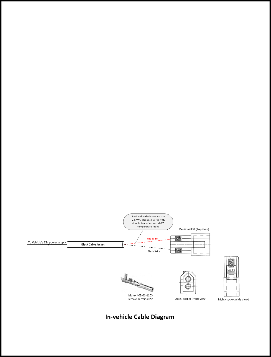
9.1.1 In-vehicle (Taxi) Cable
The installer is expected to use the required length of cable with a mating Female Molex socket
using the wiring diagram given in this section.
The In-vehicle Cable diagram below shows how one end of the black cable jacket is connected to
a Molex socket #03-06-2023!using red and black wires (crimped with crimp pins Molex # 02-06-
1103, 2 per socket). The other end of the cable is connected to the 12V power supply of the
vehicle, with red connected to the +12 V and black connected to Gnd (0v). It also shows front and
side views of the Molex socket used and a Molex #02-06-1103 female terminal pin.
Savari S-50 Operations, Administration, Maintenance & Provisioning Guide
Savari Inc., Confidential
Copyright © Savari, Inc, 2014
18
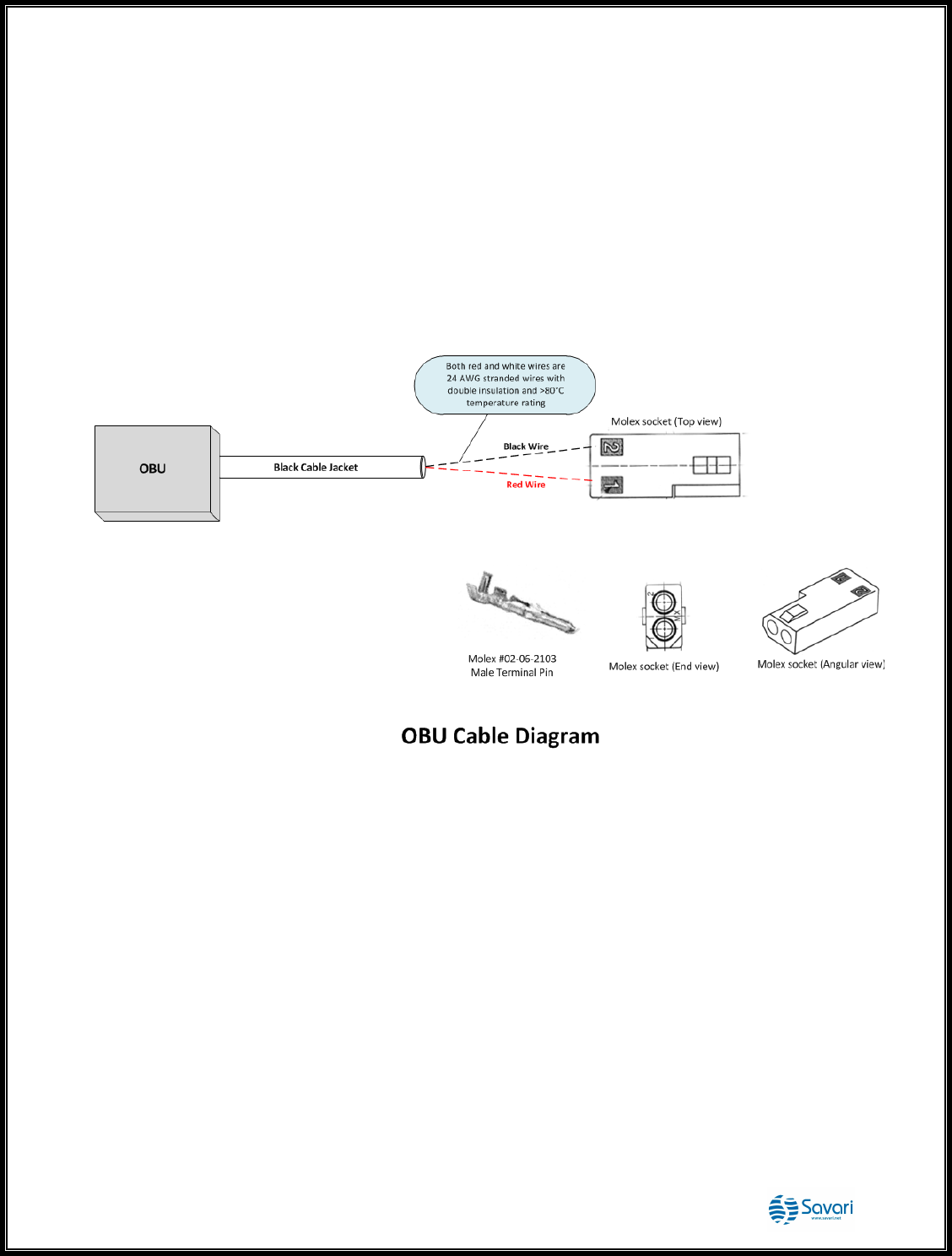
9.2 OBU Cable
The OBU Cable diagram below shows how the OBU is connected to the Male Molex connector
using red and black wires, with red connected to +12v and black connected to Gnd (0v). It also
shows angular and end views of the Molex connector used and a Molex #02-06-2103 male
terminal pin. Note that the part number of the Molex socket used is ’03-06-1023’. The socket must
be crimped with crimp pins Molex # 02-06-2103 (2 per socket).
Note: For information on how to strip and connect the wires, refer to the “Molex Application
Tooling Specification Sheet (Order No. 63819-1300)”.

Savari S-50 Operations, Administration, Maintenance & Provisioning Guide
Savari Inc., Confidential
Copyright © Savari, Inc, 2014
19
FCC
IMPORTANT NOTE: FCC Radiation Exposure Statement:
This equipment complies with FCC radiation exposure limits set forth for an uncontrolled environment.
This equipment should be installed and operated with minimum distance 20cm between the radiator &
your body. This transmitter must not be co‐located or operating in conjunction with any other antenna
or transmitter. The availability of some specific channels and/or operational frequency bands are
country dependent and are firmware programmed at the factory to match the intended destination. The
firmware setting is not accessible by the end user.
Wireless 5 GHz Band Statements:
This module could only been operated at 5850‐5925 MHz frequency band.