Savi Technology 600SP-V4 Inductive Loop Transmitter User Manual
Savi Technology Inc Inductive Loop Transmitter
Users Manual

(FKR3RLQW6LJQSRVW
,QVWDOODWLRQ*XLGH
9HUVLRQ
LL (FKR3RLQW6LJQSRVW,QVWDOODWLRQ*XLGH
First edition (September 2001)
Part number 805-03634-001 Rev. C
Copyright © 2002 Savi Technology, Inc. All rights reserved. Printed in the United States of
America.
Information in this manual is subject to change without notice and does not represent a commitment
from the vendor. The software and/or databases described in this document are furnished under a
license agreement or nondisclosure agreement. The software and/or databases may be used or copied
only in accordance with the terms of the agreement. It is against the law to copy the software on any
medium except as specifically allowed in the license or nondisclosure agreement.
Savi, Batch Collection, and TyTag are registered trademarks and Adaptive Routing, EchoPoint,
EchoPoint Signpost, Enhanced Batch Collection, Hand Held Interrogator (HHI), Savi Asset
Manager, Savi Fixed Interrogator, Savi GateReader, Savi Mobile Manager, Savi MobileReader,
Savi Retriever, Savi SDK, Savi SmartChain, Savi System, Savi Tools, SaviReader, SaviTag,
and SealTag are trademarks of Savi Technology, Inc.
Other product names mentioned in this guide may be trademarks or registered trademarks of their
respective owners and are hereby acknowledged.
This manual was produced by the Savi Technology Publications Group. Please address any
comments or requests for updates to:
Savi Technology, Inc.
Publications Manager
615 Tasman Drive
Sunnyvale, CA 94089-1707
Phone: 1-408-743-8000
Facsimile 1-408-543-8650
Web Site: http: //www.savi.com
Author: Marlowe Conde
Contributors: Joseph Chan, John Gamble, Frank Heigh, Ralph Orton, Gustavo Padilla
Layout Design and Production: Marlowe Conde

865HJXODWRU\$SSURYDOV
(FKR3RLQW6LJQSRVW,QVWDOODWLRQ*XLGH LLL
865HJXODWRU\$SSURYDOV
(FKR3RLQW6LJQSRVW
0RGHOV 6363
63DQG63
)HGHUDO&RPPXQLFDWLRQV&RPPLVVLRQ
)&&1RWLFH
The Federal Communications Commission has established technical standards
regarding radio frequency energy emitted by computer devices. This equipment has
been tested and found to comply with the limits for a Class A digital device, pursuant
to Part 15 of the FCC Rules. These limits are designed to provide reasonable
protection against harmful interference when the equipment is operated in a
commercial environment. This equipment generates, uses, and can radiate radio
frequency energy and, if not installed and used in accordance with the instruction
manual, may cause harmful interference with radio/TV reception. Operation of this
equipment in a residential area is likely to cause harmful interference in which case
the user will be required to correct the interference at his own expense.
Changes or modifications to this equipment that are not
expressly approved by Savi Technology could void the
warranty and the authority to operate this equipment.
Savi Technology is not responsible for radio/TV
interference caused by using unauthorized cable or
by making unauthorized changes to this equipment.
3URGXFW6DIHW\
The EchoPoint Signpost SP-600-101, SP-600-111, SP-600-201, and SP-600-211
are ETL listed (UL 1950).

LY (FKR3RLQW6LJQSRVW,QVWDOODWLRQ*XLGH
865HJXODWRU\$SSURYDOV
1HWZRUN$GDSWHU
0RGHO 6$
)HGHUDO&RPPXQLFDWLRQV&RPPLVVLRQ
)&&1RWLFH
The Federal Communications Commission has established technical standards
regarding radio frequency energy emitted by computer devices. This equipment has
been tested and found to comply with the limits for a Class A digital device, pursuant
to Part 15 of the FCC Rules. These limits are designed to provide reasonable
protection against harmful interference when the equipment is operated in a
commercial environment. This equipment generates, uses, and can radiate radio
frequency energy and, if not installed and used in accordance with the instruction
manual, may cause harmful interference with radio/TV reception. Operation of this
equipment in a residential area is likely to cause harmful interference in which case
the user will be required to correct the interference at his own expense.
Changes or modifications to this equipment that are not
expressly approved by Savi Technology could void the
warranty and the authority to operate this equipment.
Savi Technology is not responsible for radio/TV
interference caused by using unauthorized cable or
by making unauthorized changes to this equipment.
,QWHUQDWLRQDO5HJXODWRU\$SSURYDOV
(FKR3RLQW6LJQSRVW,QVWDOODWLRQ*XLGH Y
,QWHUQDWLRQDO5HJXODWRU\$SSURYDOV
(FKR3RLQW6LJQSRVW
0RGHOV 6363
63DQG63
'HFODUDWLRQRI&RQIRUPLW\
Hereby, Savi Technology, Inc.
615 Tasman Drive
Sunnyvale, California 94089-1707
declares that the EchoPoint Signpost models SP-600-101, SP-600-111, SP-600-201,
and SP-600-211 are in compliance with the essential requirements and other
relevant provisions as listed in the International Compliance table below.
,QWHUQDWLRQDO&RPSOLDQFH
English Hereby, Savi Technology, Inc., declares that this EchoPoint
Signpost (models SP-600-101, SP-600-111, SP-600-201, and
SP-600-211) is in compliance with the essential requirements
and other relevant provisions of Directive 1999/5/EC.
Finnish Savi Technology, Inc. vakuuttaa täten että EchoPoint Signpost
(models SP-600-101, SP-600-111, SP-600-201, and SP-600-211)
tyyppinen laite on direktiivin 1999/5/EY oleellisten vaatimusten
ja sitä koskevien direktiivin muiden ehtojen mukainen.
Dutch Hierbij verklaart Savi Technology, Inc. dat het toestel EchoPoint
Signpost (models SP-600-101, SP-600-111, SP-600-201, and
SP-600-211) in overeenstemming is met de essentiële eisen en
de andere relevante bepalingen van richtlijn 1999/5/EG.
Bij deze verklaart Savi Technology, Inc. dat deze EchoPoint
Signpost (models SP-600-101, SP-600-111, SP-600-201, and
SP-600-211) voldoet aan de essentiële eisen en aan de overige
relevante bepalingen van Richtlijn 1999/5/EC.
French Par la présente Savi Technology, Inc. déclare que l'appareil
EchoPoint Signpost (models SP-600-101, SP-600-111, SP-600-201,
and SP-600-211) est conforme aux exigences essentielles et aux
autres dispositions pertinentes de la directive 1999/5/CE.
0889

3URGXFW6DIHW\
CB Scheme (IEC 60950).
French Par la présente, Savi Technology, Inc. déclare que ce EchoPoint
Signpost (models SP-600-101, SP-600-111, SP-600-201, and
SP-600-211) est conforme aux exigences essentielles et aux autres
dispositions de la directive 1999/5/CE qui lui sont applicables.
Swedish Härmed intygar Savi Technology, Inc. att denna EchoPoint Signpost
(models SP-600-101, SP-600-111, SP-600-201, and SP-600-211)
står I överensstämmelse med de väsentliga egenskapskrav och
övriga relevanta bestämmelser som framgår av direktiv 1999/5/EG.
Danish Undertegnede Savi Technology, Inc.erklærer herved, at følgende
udstyr EchoPoint Signpost (models SP-600-101, SP-600-111,
SP-600-201, and SP-600-211) overholder de væsentlige krav og
øvrige relevante krav i direktiv 1999/5/EF.
German Hiermit erklärt Savi Technology, Inc., dass sich dieser/diese/dieses
EchoPoint Signpost (models SP-600-101, SP-600-111,
SP-600-201, and SP-600-211) in Übereinstimmung mit den
grundlegenden Anforderungen und den anderen relevanten
Vorschriften der Richtlinie 1999/5/EG befindet". (BMWi)
Hiermit erklärt Savi Technology, Inc. die Übereinstimmung des
Gerätes EchoPoint Signpost (models SP-600-101, SP-600-111,
SP-600-201, and SP-600-211) mit den grundlegenden
Anforderungen und den anderen relevanten Festlegungen der
Richtlinie 1999/5/EG. (Wien)
Greek ΜΕ ΤΗΝ ΠΑΡΟΥΣΑ 6DYL7HFKQRORJ\,QF∆ΗΛΩΝΕΙ ΟΤΙ
(FKR3RLQW6LJQSRVWmodels 6363
63DQG63ΣΥΜΜΟΡΦΩΝΕΤΑΙ ΠΡΟΣ ΤΙΣ
ΟΥΣΙΩ∆ΕΙΣ ΑΠΑΙΤΗΣΕΙΣ ΚΑΙ ΤΙΣ ΛΟΙΠΕΣ ΣΧΕΤΙΚΕΣ
∆ΙΑΤΑΞΕΙΣ ΤΗΣ Ο∆ΗΓΙΑΣ 1999/5/ΕΚ.
Italian Con la presente Savi Technology, Inc. dichiara che questo
EchoPoint Signpost (models SP-600-101, SP-600-111,
SP-600-201, and SP-600-211) è conforme ai requisiti essenziali ed
alle altre disposizioni pertinenti stabilite dalla direttiva 1999/5/CE.
Spanish Por medio de la presente Savi Technology, Inc. declara que el
EchoPoint Signpost (models SP-600-101, SP-600-111,
SP-600-201, and SP-600-211) cumple con los requisitos
esenciales y cualesquiera otras disposiciones aplicables o
exigibles de la Directiva 1999/5/CE.
Portuguese Savi Technology, Inc. declara que este EchoPoint Signpost
SP-600-101, SP-600-111, SP-600-201, and SP-600-211 está
conforme com os requisitos essenciais e outras disposições da
Directiva 1999/5/CE.
&RQYHQWLRQVLQ7KLV*XLGH
(FKR3RLQW6LJQSRVW,QVWDOODWLRQ*XLGH YLL
&RQYHQWLRQVLQ7KLV*XLGH
The following table explains guide conventions and typography usage.
*XLGH&RQYHQWLRQV
Example Meaning and Use
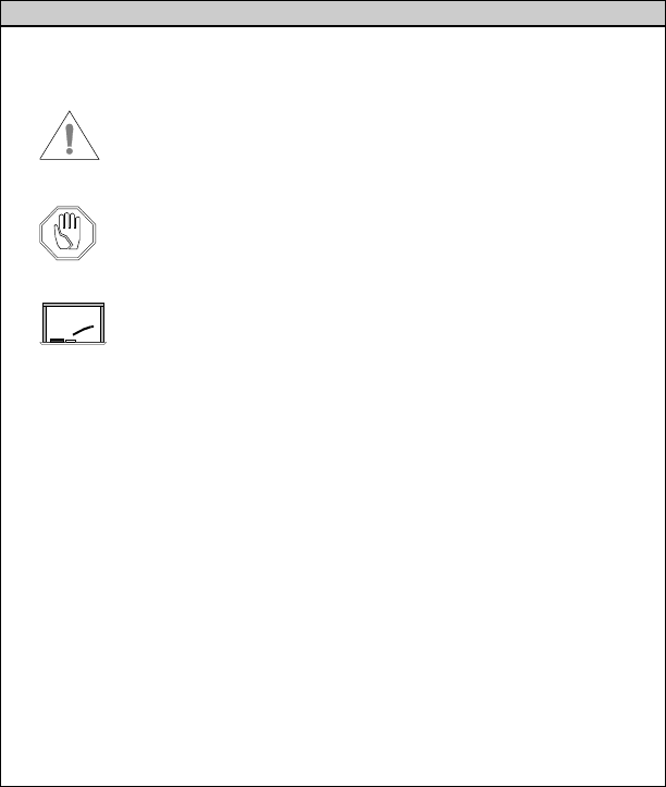
Note: Notes call attention to facts or advice that deserve
special attention.
Caution notices call attention to the possibility of
damaging the product, the system, or your work
(for example, potential loss of data).
Warning notices call attention to the possibility
of injury to people.
Examples provide a scenario to further explain the
preceding direction or procedure.
7HUPLQDO/RFNHG Bold type is used for prompts, field names, and other
text as displayed on the screen.
$?,167$// Bold type is also used for text you enter exactly
as shown.
'$7$ Monospaced type is used for system messages, examples
of data files, program code, and other text where column
alignment is important.
name.bmp or tag_id Italic type is used for emphasis of a word or phrase that
is new or especially important.
&WUO + =Used for a keyboard control codes or manual keystrokes.
This example tells you to hold the &WUO key while you
press the =key.
Example
7DEOHRI&RQWHQWV
(FKR3RLQW6LJQSRVW,QVWDOODWLRQ*XLGH L[
U.S. Regulatory Approvals . . . . . . . . . . . . . . . . . . . . . . . . . . . iii
EchoPoint Signpost . . . . . . . . . . . . . . . . . . . . . . . . . . . . . iii
Network Adapter . . . . . . . . . . . . . . . . . . . . . . . . . . . . . . . iv
International Regulatory Approvals . . . . . . . . . . . . . . . . . . . . .v
EchoPoint Signpost . . . . . . . . . . . . . . . . . . . . . . . . . . . . . v
Conventions in This Guide . . . . . . . . . . . . . . . . . . . . . . . . . . .vii
Chapter 1: Introduction
EchoPoint Signpost Description . . . . . . . . . . . . . . . . . . . . . . 1-2
Models SP-600-201 and SP-600-211 . . . . . . . . . . . . . . . 1-2
Model SP-600-101 and SP-600-111. . . . . . . . . . . . . . . . 1-3
Specifications . . . . . . . . . . . . . . . . . . . . . . . . . . . . . . . . . . . . 1-4
Getting Assistance. . . . . . . . . . . . . . . . . . . . . . . . . . . . . . . . . 1-5
Customer Support. . . . . . . . . . . . . . . . . . . . . . . . . . . . . . 1-5
Chapter 2: Hardware Installation
Required Materials and Equipment. . . . . . . . . . . . . . . . . . . . 2-2
Preparing the Site . . . . . . . . . . . . . . . . . . . . . . . . . . . . . . . . . 2-3
Mounting the Signposts . . . . . . . . . . . . . . . . . . . . . . . . . . . . 2-5
Mounting the Model SP-600-201 or SP-600-211
Signpost . . . . . . . . . . . . . . . . . . . . . . . . . . . . . . . . . . . . . 2-5
Mounting the Model SP-600-101 or SP-600-111
Signpost . . . . . . . . . . . . . . . . . . . . . . . . . . . . . . . . . . . . . 2-8
Cabling the Model SP-600-201 or SP-600-211
Signpost . . . . . . . . . . . . . . . . . . . . . . . . . . . . . . . . . . . . 2-10
Cabling the Model SP-600-101 or SP-600-111
Signpost . . . . . . . . . . . . . . . . . . . . . . . . . . . . . . . . . . . . 2-14
Signpost Synchronization . . . . . . . . . . . . . . . . . . . . . . . . . . 2-16
Chapter 3: Signpost Configuration
Connecting Signposts to a Computer . . . . . . . . . . . . . . . . . . 3-2
Configuring Signpost Operation Settings . . . . . . . . . . . . . . . 3-3

(FKR3RLQW6LJQSRVW,QVWDOODWLRQ*XLGH
,QWURGXFWLRQ 1
This guide describes how to install the EchoPoint Signpost, including
hardware installation and using the software to configure the Signpost.
Signposts are short-range transmitters that provide their identity
information to the EchoPoint Series 600 tags (Tags) that are within
range. A Tag uses this information to relay positional information
about itself to an EchoPoint Reader SR-600-101 (Reader). The
Reader then provides this information to the Savi SmartChain system
software where it is used for asset management.
This chapter introduces the Signpost types, and provides references
to other chapters having detailed Signpost setup, installation,
and configuration information. EchoPoint Signposts are used in
conjunction with other Savi equipment, including the Savi Site
Managers and Readers. Installation and use of these components is
documented in their respective user guides. For information on setting
up the EchoPoint Reader SR-600-101, refer to the EchoPoint Reader
SR-600-101 Installation Guide. For information on setting up a Savi
Site Manager, refer to the Site Manager Installation Guide.
(FKR3RLQW6LJQSRVW'HVFULSWLRQ
(FKR3RLQW6LJQSRVW,QVWDOODWLRQ*XLGH
(FKR3RLQW6LJQSRVW'HVFULSWLRQ
The EchoPoint Signpost is available in four configurations. Models
SP-600-201 and SP-600-211 have an external antenna. Models
SP-600-101 and SP-600-111 have an internal antenna.
Models SP-600-101 and SP-600-201 operate at a nominal frequency
of 132 kHz. Whereas, Models SP-600-111 and SP-600-211 operate
at a lower nominal frequency of 123 kHz.
0RGHOV63DQG63
The EchoPoint Signpost SP-600-201 and SP-600-211 have a two-part
assembly consisting of a controller attached to an antenna. They are
powered by AC or DC, with the AC having a range of 85 to 264 Volts
at 47 to 440 Hz, while the DC range is 11 to 30 Volts.
0RGHOV63DQG63
6LJQSRVW&DEOHVDQG+DUGZDUH
Signpost Models SP-600-201 and SP-600-211 installation materials
include:
•DC, 115 VAC, 220 VAC power cable (one supplied)
•Signpost configuration software
•Mounting kit
•Sensor cables (optional)
•Synchronization cables (optional)
(FKR3RLQW6LJQSRVW'HVFULSWLRQ
(FKR3RLQW6LJQSRVW,QVWDOODWLRQ*XLGH
0RGHOV63DQG63
The EchoPoint Signpost SP-600-101 and SP-600-111 have a one-part
assembly consisting of a controller with a built-in antenna. Like the
Model SP-600-201 or SP-600-211 Signpost, the Model SP-600-101
and SP-600-111 Signposts are powered by AC or DC, with the AC
having a range of 85 to 264 Volts at 47 to 440 Hz, while the DC range
is 11 to 30 Volts.
0RGHOV636LJQSRVW&DEOHV
DQG+DUGZDUH
Signpost Models SP-600-101 and SP-600-111 installation materials
include:
•DC, 115 VAC, 220 VAC power cable (one supplied)
•Signpost configuration software
•Mounting feet
•Sensor cables (optional)
•Synchronization cables (optional)

6SHFLILFDWLRQV
(FKR3RLQW6LJQSRVW,QVWDOODWLRQ*XLGH
6SHFLILFDWLRQV
EchoPoint Signpost specifications are documented in Table 1-1.
7DEOH 6LJQSRVW6SHFLILFDWLRQV
Signpost Type Specification
Model
SP-600-201 and
SP-600-211
Signpost
Power AC or DC
AC range 85–264 Volts at 47 to 440 Hz, 800/400 ma
DC range 11–30 Volts, 800 ma
Weight 14.7 pounds (with controller mounted)
2 pounds (controller)
Dimensions 19.5" x 109.25" x 4.8"
19.5" x 109.25" x 2.5" (without controller)
7.5" x 7.5" x 3" (controller)
Model
SP-600-101 and
SP-600-111
Signpost
Power AC or DC
AC range 85–264 Volts at 47 to 440 Hz, 800/400 ma
DC range 11–30 Volts, 800 ma
Weight 2.9 pounds
Dimensions 10.5" x 7" x 3" (includes the protrusion for
the connectors without the cables attached)
*HWWLQJ$VVLVWDQFH
(FKR3RLQW6LJQSRVW,QVWDOODWLRQ*XLGH
*HWWLQJ$VVLVWDQFH
If you have trouble with the product, after you have checked your
connections and the EchoPoint Signpost Installation Guide,
contact Savi Customer Support.
&XVWRPHU6XSSRUW
To contact Savi Customer Support:
•Telephone 1-888-994-SAVI (7284) between 8:00 a.m.
and5:00p.m.
, Pacific Time
•Or send e-mail to help@savi.com at any time
Whether you contact Savi by telephone or e-mail, please have
the exact sequence of operations (if possible) that caused the
problem and the following information available:
•Site location
•Incident description
•Estimated severity level of the incident
•Model number and version
•Serial number
•Computer type (Gateway, Dell, etc.) and model
•Operating system and service pack level
•Network protocol

(FKR3RLQW6LJQSRVW,QVWDOODWLRQ*XLGH
+DUGZDUH
,QVWDOODWLRQ 2
This chapter covers installing the EchoPoint Signpost Model
SP-600-201, SP-600-211, SP-600-101, and SP-600-111 hardware,
including the required tools and materials, site preparation, and
making the physical installation and power connections.

5HTXLUHG0DWHULDOVDQG(TXLSPHQW
(FKR3RLQW6LJQSRVW,QVWDOODWLRQ*XLGH
5HTXLUHG0DWHULDOVDQG
(TXLSPHQW
The required materials, equipment, and tools for installing all
EchoPoint Signpost models are listed in Table 2-1.
7DEOH 0DWHULDO(TXLSPHQWDQG7RROV5HTXLUHGIRU,QVWDOOLQJ6LJQSRVWV
Signpost Required Material, Equipment, and Tools
SP-600-201
and
SP-600-211
Model SP-600-201 or SP-600-211 Signpost
Power source: 115 to 220 VAC, or 11 to 30 VDC
Mounting hardware
RS-232 cable
Computer with Signpost configuration software installed
Optional equipment, including sensor cable and
synchronization cables
SP-600-101
and
SP-600-111
Model SP-600-101 or SP-600-111 Signpost
Power source: 115 to 220 VAC, or 11 to 30 VDC
Mounting feet
RS-232 cable
Computer with Signpost configuration software installed
Optional equipment, including sensor cable and
synchronization cables

3UHSDULQJWKH6LWH
(FKR3RLQW6LJQSRVW,QVWDOODWLRQ*XLGH
3UHSDULQJWKH6LWH
Mounting a Signpost requires no specific site preparation. The criteria
for placement and the preparation include the considerations listed in
Table 2-2.
7DEOH 6LWH3UHSDUDWLRQ&RQVLGHUDWLRQV
Consideration Addressed by ...
Safety Avoid selecting a Signpost installation location
where harm to the equipment or personnel is
possible.
Power Select an installation location where power is
accessible.
Space Allow sufficient space to install the Signpost.
Coverage Make sure that the installation location is
appropriate for capturing data.
Models SP-600-201 and SP-600-211 Signpost
coverage is a rectangle with rounded corners that
is approximately 12 feet by 10 feet, measured on
the floor under the Signpost antenna.
Models SP-600-101 and SP-600-111 Signpost
coverage is a circle with a radius that is
approximately 6 feet.
Note: The exact size and shape of these patterns
is dependent on several parameters, such as
initial power settings during installation, ambient
noise levels, and nearby obstructions. When
installing, you need to experiment to determine
actual performance based on needs.
Placement Signposts should be placed adjacent to a portal
or other choke point, covering an area where the
assets must pass or be stored.

3UHSDULQJWKH6LWH
(FKR3RLQW6LJQSRVW,QVWDOODWLRQ*XLGH
Locations not
permitted Signposts must not be used in areas not permitted
by government regulation. Savi can help with
determining applicable countries and locations.
Overhead support for
Model SP-600-201
and SP-600-211
Signposts
Determine the layout and capacity of the
overhead structure that will be supporting the
Signpost Model SP-600-201 and SP-600-211
assemblies, including the Signpost and antenna
(weight 14.7 pounds). Securely attach the
mounting hardware to structural members such
as joists, girders, purlins, headers, and beams.
For more information on mounting the Model
SP-600-201 or SP-600-211 Signpost, see
“Mounting the Signposts” on page 2-5.
7DEOH 6LWH3UHSDUDWLRQ&RQVLGHUDWLRQV
Consideration Addressed by ...
0RXQWLQJWKH6LJQSRVWV
(FKR3RLQW6LJQSRVW,QVWDOODWLRQ*XLGH
0RXQWLQJWKH6LJQSRVWV
This section covers the installation procedures for Model
SP-600-201, SP-600-211, SP-600-101, and SP-600-111 Signposts.
0RXQWLQJWKH0RGHO63RU
636LJQSRVW
Model SP-600-201 and SP-600-211 Signposts can be hung adjacent to
a portal or other choke point using the supplied installation hanger kit.
The actual installation is dependent on the individual circumstances
and how power is to be supplied, but a number of tasks need to be
performed in all cases.
0RXQWLQJWKH6LJQSRVWV
(FKR3RLQW6LJQSRVW,QVWDOODWLRQ*XLGH
» To mount a Model SP-600-201 or SP-600-211 Signpost:
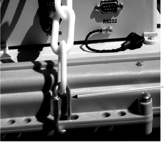
1. Attach a removable 1/8 inch link to each of the four mounting
brackets at the four corners of the unit.
)LJXUH 5HPRYDEOH/LQN
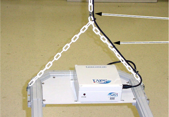
2. Using two lengths of plastic chain, attach each at both ends to
the four removable links, as shown in Figure 2-1 and Figure 2-2.
5HPRYDEOH
OLQN
0RXQWLQJWKH6LJQSRVWV
(FKR3RLQW6LJQSRVW,QVWDOODWLRQ*XLGH
)LJXUH $WWDFKLQJ&KDLQ
3. Attach another removable link to the center of the chain, as
shown in Figure 2-2 above.
4. Attach the top removable link to an appropriate rope, cable, or
chain and fasten to a 3/8 inch eye screw or eye bolt (minimum
1-1/2 inch penetration into solid material, or through bolt).
5. Secure the power cord to the chain and route as required.
5HPRYDEOH
OLQN
3ODVWLFFKDLQ
0RXQWLQJWKH6LJQSRVWV
(FKR3RLQW6LJQSRVW,QVWDOODWLRQ*XLGH
0RXQWLQJWKH0RGHO63RU
636LJQSRVW
Model SP-600-101 and SP-600-111 Signposts are supplied with
mounting feet. The actual installation is dependent on the individual
circumstances and how power is to be supplied, but a number of tasks
need to be performed in all cases.
»To mount a Model SP-600-101 or SP-600-111 Signpost:
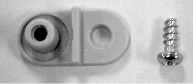
1. Attach the mounting feet.
Figure 2-3 below shows the mounting feet with the self-tapping
screws that attach them to the Signpost.
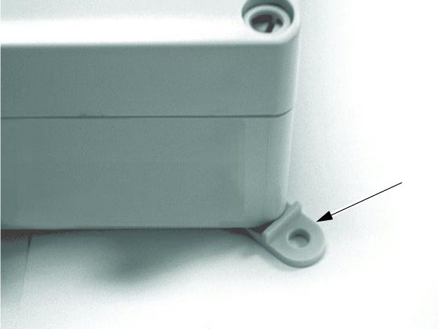
Figure 2-4 on page 2-9 shows a single mounting foot attached to
the Signpost. In this case it is mounted at an angle, but the foot
can be turned at different angles.
)LJXUH 0RXQWLQJ)RRWDQG$WWDFKPHQW6FUHZ
0RXQWLQJWKH6LJQSRVWV
(FKR3RLQW6LJQSRVW,QVWDOODWLRQ*XLGH
)LJXUH 0RXQWLQJ)RRW$WWDFKHGWR0RGHO63RU636LJQSRVW
2. Attach the mounting feet to the mounting surface.
DO NOT attach the mounting feet to drywall only, unless the
drywall is backed by solid structural material, in which case
screws need to penetrate a minimum of 3/4 inch into solid
material.
$WWDFKHG
PRXQWLQJ
IRRW
0RXQWLQJWKH6LJQSRVWV
(FKR3RLQW6LJQSRVW,QVWDOODWLRQ*XLGH
&DEOLQJWKH0RGHO63RU
636LJQSRVW
The only cabling required for a basic installation is operating power.
This needs to be done in accordance with applicable safety regulations.
All cables should be routed and protected in a manner which precludes
damage to them or harm to personnel; for example, unsecured
extension cords left across access-ways or where assets or asset
moving equipment can damage them.
This section does not include connecting the Signpost to a computer
with a serial cable for Signpost software configuration. That activity
is covered in Chapter 3, “Signpost Configuration.”
The connectors and LED shown in Table 2-3 are available on a Model
SP-600-201 or SP-600-211 Signpost.

0RXQWLQJWKH6LJQSRVWV
(FKR3RLQW6LJQSRVW,QVWDOODWLRQ*XLGH
7DEOH 0RGHO63DQG636LJQSRVW&RQQHFWRUVDQG/('V
Connectors
and LEDs Description
Power The input power is connected here.
RS-232 Used to connect to a computer for setup and diagnostics by
installers and technicians.
Antenna The external loop antenna connects here.
Sync In Used to synchronize 2 to 4 Model SP-600-201 or SP-600-211
Signposts to cover an area larger than is possible with a
single Signpost. This connector can also accept DC volts
from another Signpost to avoid running separate power lines
when two or more Signposts are synchronized.
Sync Out Used to synchronize 2 to 4 Model SP-600-201 or SP-600-211
Signposts to cover an area larger than is possible with a
single Signpost. This connector can also output DC volts to
another Signpost to avoid running separate power lines when
two or more Signposts are synchronized.
Sensor 1 A closure on these two pins will trigger a predefined
Signpost action.
Sensor 2 A closure on these two pins will trigger a predefined
Signpost action.
Status This LED indicates when power is applied and the Signpost
mode of operation:
On ½ second, off ½ second indicates normal operation
On 1 second, off 1 second indicates the Signpost is off but
powered
On continuously indicates the Signpost is transmitting a CW
signal
0RXQWLQJWKH6LJQSRVWV
(FKR3RLQW6LJQSRVW,QVWDOODWLRQ*XLGH
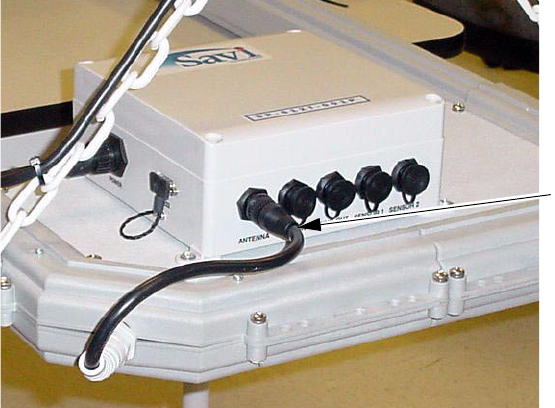
»To cable a Model SP-600-201 or SP-600-211 Signpost:
No cabling is required for the Model SP-600-201 or SP-600-211
Signpost and its antenna. This connection has already been made,
as shown in Figure 2-5.
)LJXUH 0RGHO63RU636LJQSRVW$QWHQQD&RQQHFWLRQ
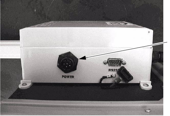
1. Run the appropriate power cable to the Signpost.
2. Connect the power cable to the Signpost Power connector,
as shown in Figure 2-6.
Note: The socket-outlet shall be installed near the
equipment and shall be easily accessible.
$QWHQQD
FRQQHFWLRQ

0RXQWLQJWKH6LJQSRVWV
(FKR3RLQW6LJQSRVW,QVWDOODWLRQ*XLGH
&DEOLQJWKH0RGHO63RU
636LJQSRVW
The connectors and LED shown in Table 2-4 are available on a Model
SP-600-101 and SP-600-111 Signpost.
7DEOH 0RGHO63DQG636LJQSRVW&RQQHFWRUVDQG/('V
Connectors
and LEDs Description
Power The input power is connected here.
RS-232 Used to connect to a computer for setup and diagnostics by
installers and technicians.
Sync In Used to synchronize 2 to 4 Model SP-600-101 or SP-600-111
Signposts to cover an area larger than is possible with a single
Signpost. This connector can also accept DC volts from
another Signpost to avoid running separate power lines when
two or more Signposts are synchronized.
Sync Out Used to synchronize 2 to 4 Model SP-600-101 or SP-600-111
Signposts to cover an area larger than is possible with a single
Signpost. This connector can also output DC volts to another
Signpost to avoid running separate power lines when two or
more Signposts are synchronized.
Sensor 1 A closure on these two pins will trigger a predefined Signpost
action.
Sensor 2 A closure on these two pins will trigger a predefined Signpost
action.
Status This LED indicates when power is applied and the Signpost
mode of operation:
On ½ second, off ½ second indicates normal operation
On 1 second, off 1 second indicates the Signpost is off but
powered
On continuously indicates the Signpost is transmitting a CW
signal
0RXQWLQJWKH6LJQSRVWV
(FKR3RLQW6LJQSRVW,QVWDOODWLRQ*XLGH
»To cable a Model SP-600-101 or SP-600-111 Signpost:
1. Cable the Model SP-600-101 or SP-600-111 the same as the
Model SP-600-201 or SP-600-211.
For cabling, the Model SP-600-101 and SP-600-111 are identical
to the cabling for the Model SP-600-201 or SP-600-211 except
that the Model SP-600-101 and SP-600-111 have an internal
antenna.
See “Cabling the Model SP-600-201 or SP-600-211 Signpost”
on page 2-10.
2. Continue with configuration using the Signpost configuration
software.
See “Configuring Signpost Operation Settings” on page 3-3.
6LJQSRVW6\QFKURQL]DWLRQ
(FKR3RLQW6LJQSRVW,QVWDOODWLRQ*XLGH
6LJQSRVW6\QFKURQL]DWLRQ
For a transmit group to work, the Sync cable must be connected
between the Signposts. These optional cables are available from
Savi Technology in variable lengths.
»To cable a Signpost for synchronization:
1. Connect the female end of the cable to the Sync In connector
of the Signpost.
2. Connect the male end of the cable to the Sync Out connector
of another Signpost in the synchronized group.
3. Create group number assignments.
See “Configuring Signpost Operation Settings” on page 3-3.

(FKR3RLQW6LJQSRVW,QVWDOODWLRQ*XLGH
6LJQSRVW
&RQILJXUDWLRQ 3
Signpost operation requires that you configure some Signpost
parameters using the Signpost configuration software application.
This chapter provides instructions for connecting Signposts to the
computer and configuring Signposts using the software.
Note: It is assumed that the Signpost configuration software
application is installed on the computer being used
to configure a Signpost.
&RQQHFWLQJ6LJQSRVWVWRD&RPSXWHU
(FKR3RLQW6LJQSRVW,QVWDOODWLRQ*XLGH
&RQQHFWLQJ6LJQSRVWVWRD&RPSXWHU
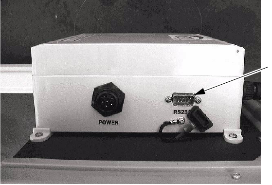
Signposts are connected to a computer with an RS-232 serial
connection. All Model SP-600-201, SP-600-211, SP-600-101, and
SP-600-111 Signposts have an RS-232 port which is temporarily used
for configuration with Signpost configuration software when the
Signpost is installed. Figure 3-1 shows the serial ports for the Model
SP-600-201 Signpost. The Model SP-600-211, SP-600-101, and
SP-600-111 RS-232 port is similar.
)LJXUH 0RGHO636LJQSRVW563RUW
56
SRUW
&RQILJXULQJ6LJQSRVW2SHUDWLRQ6HWWLQJV
(FKR3RLQW6LJQSRVW,QVWDOODWLRQ*XLGH
&RQILJXULQJ6LJQSRVW2SHUDWLRQ
6HWWLQJV
Either before or after the Signpost is installed, the installer should
set and verify the following settings for operation. This activity is
performed using a computer having the Signpost configuration
software application installed.
Before verifying these settings, you need to connect the computer
to the Signpost, which is documented in “Connecting Signposts to
a Computer” on page 3-2.
»To verify the operation settings:
The following Signpost configuration application parameters need
to be verified:
1. Configure the Signpost ID (1 to 65535)
The Signpost ID should be a unique number in the facility.
The Signpost can be identified in the system by associating this
number with a description in the Site Manager configuration.
2. Transmit group number (0 to 10)
The Transmit group number is used when a number of Signposts
are transmitting at the same time or a different time. The factory
setting is 0. The Signpost will not synchronize when the group
number is 0. When you program a number from 1 to 10, Signposts
having the same group number will transmit simultaneously.
Otherwise, they transmit at a different time.
3. Beacon Control on/off
The Beacon Control on/off option is used to program the tag
whenever changing the beacon mode of the tag is required.
When this option is disabled, the tag remains in the same mode.
When the option is enabled, the tag beacon mode will be changed
according to the command.
&RQILJXULQJ6LJQSRVW2SHUDWLRQ6HWWLQJV
(FKR3RLQW6LJQSRVW,QVWDOODWLRQ*XLGH
4. Power level
Generally, the maximum setting of 1023 is used, but this number
can be decreased to reduce power; the higher the number, the
higher the power. However, range does not increase linearly with
an increase in the power level, and may require a number of trial
settings to achieve the appropriate power level.
5. Tx mode
The Tx mode should be set to normal mode.
6. Status
The version should be verified so that all Signposts are
compatible with the system.