Savi Technology 65XSP-V2 Signpost SP-65X Series User Manual
Savi Technology Inc Signpost SP-65X Series
UserManual.wiki
>
Savi Technology
>
65XSP-V2 User Manual
>
Installers Manual
Contents
1.
Users Manual
2.
Compliance Statements
3.
Installers Manual
Installers Manual
Navigation menu
Upload a User Manual
Namespaces
Wiki Guide
HTML
PDF
Info
Views
User Manual
Discussion / Help
Navigation
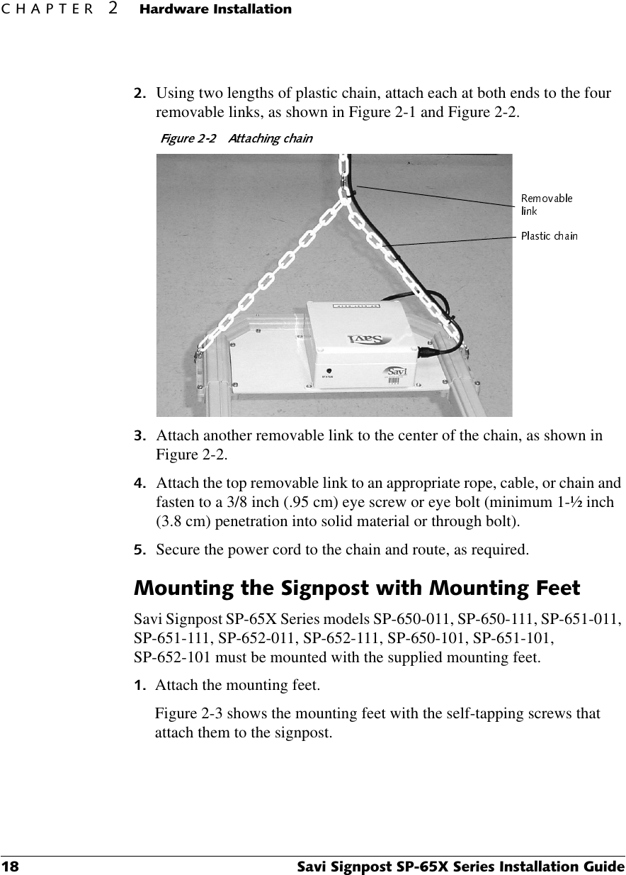
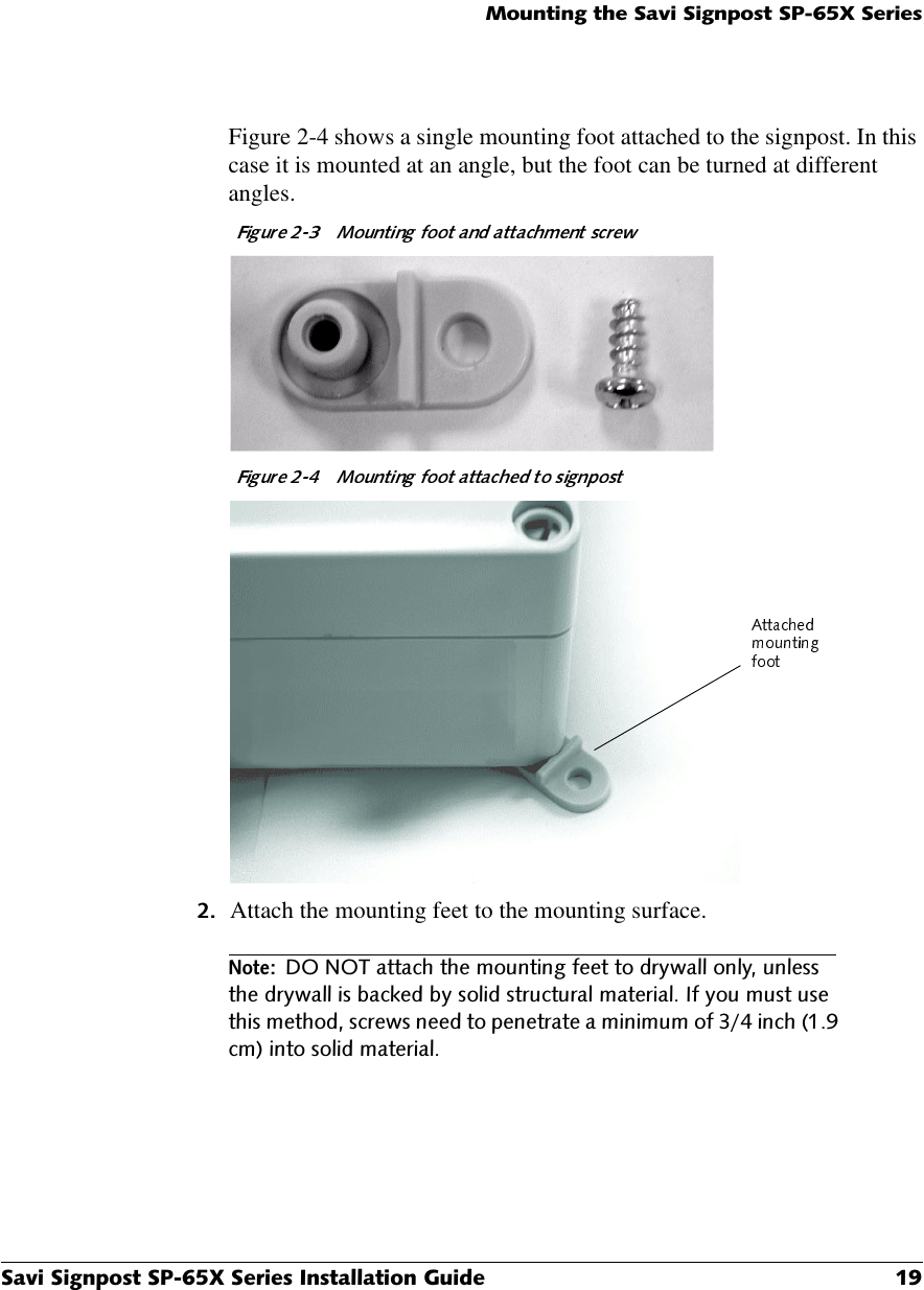
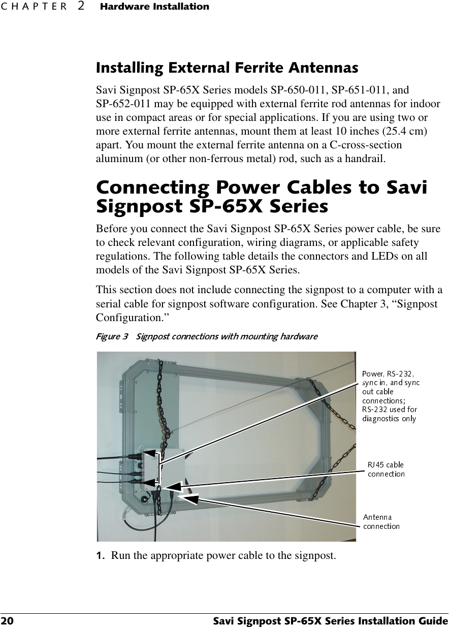
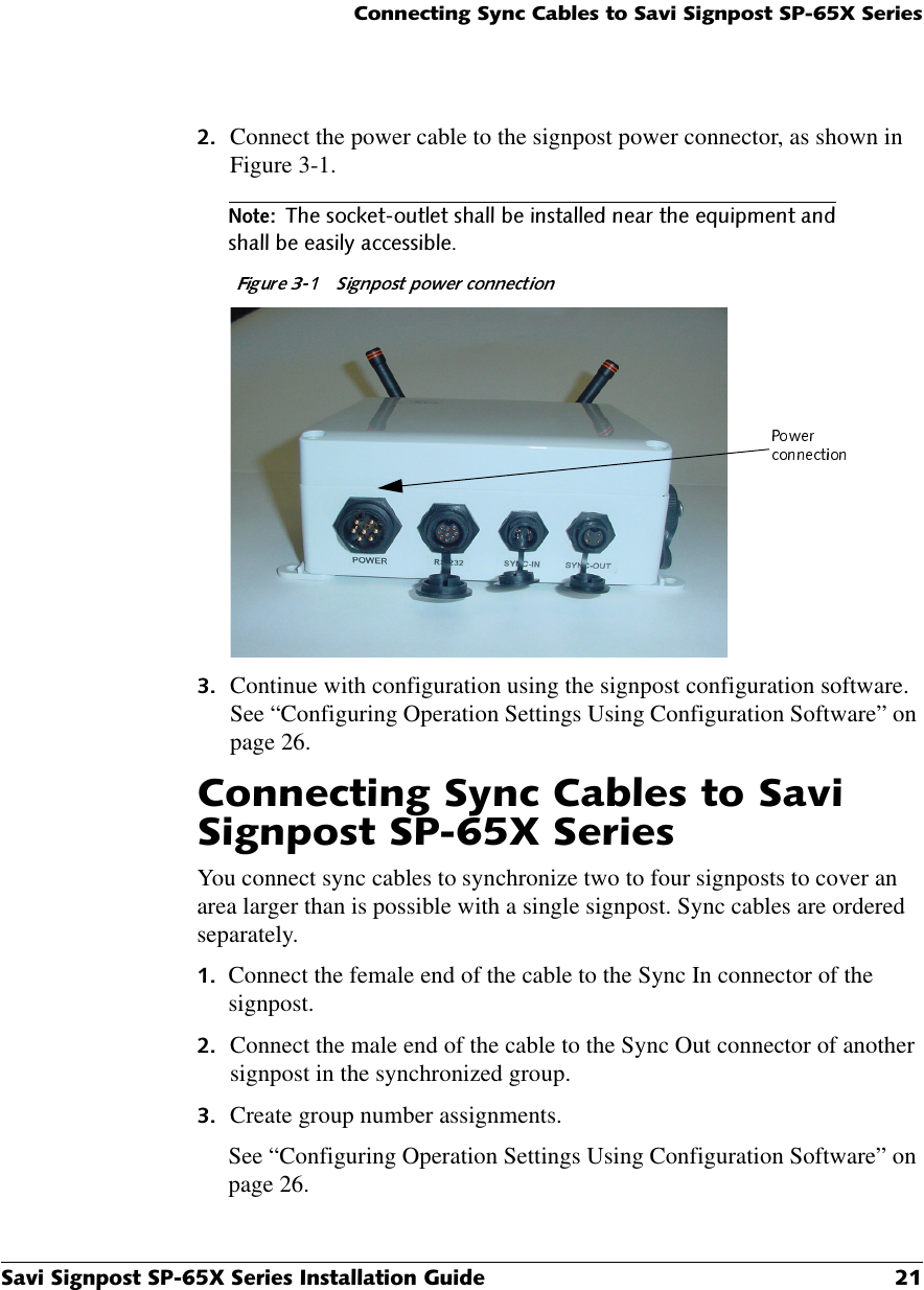

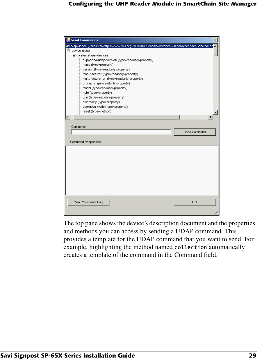
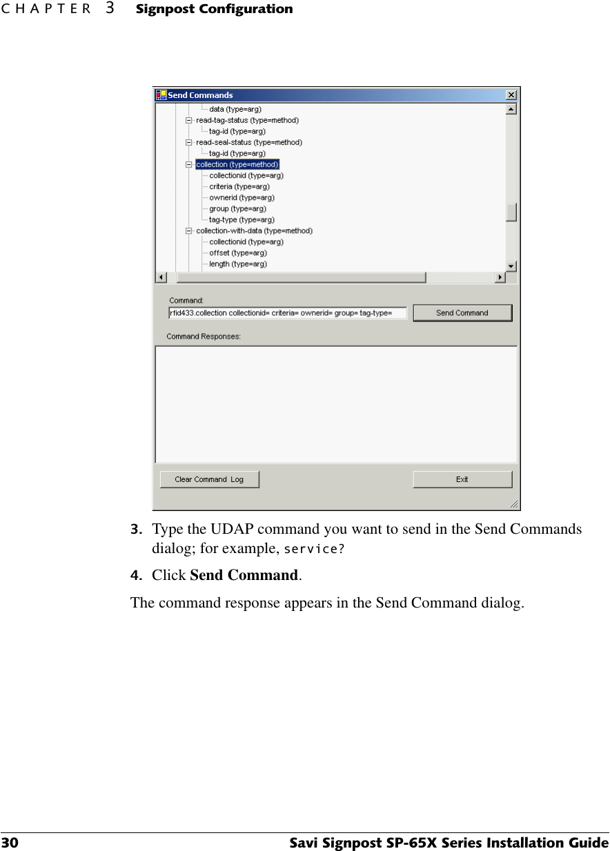
![&RQILJXULQJWKH8+)5HDGHU0RGXOHLQ6PDUW&KDLQ6LWH0DQDJHU6DYL6LJQSRVW63;6HULHV,QVWDOODWLRQ*XLGH Set the low frequency power level.For Savi Signpost SP-65X Series models SP-650-211, SP-651-211, and SP-652-211 with the large air core antennas, you use the maximum setting of 724, in compliance with international emissions standards. For all other Savi Signpost SP-65X Series models, you use the maximum setting of 1023. Set the Tx mode to normal mode. Verify the status of the signpost and that all signposts are compatible with the system.&RQILJXULQJWKH8+)5HDGHU0RGXOHLQ6PDUW&KDLQ6LWH0DQDJHUSavi Signpost SP-65X Series models SP-652-011, SP-652-111, SP-652-211, SP-652-311, SP-652-101, and SP-652-201 must be configured over the Ethernet connection and connected to SmartChain Site Manager. The UHF reader module in all of these signpost models:◆Allows you to send data from tags it receives once the host IP address is set and the time is synchronized◆Responds to tags that are triggered by the low frequency signpost signal after a UDAP command is sent6HWWLQJWKH+RVW,3$GGUHVVDQG6\QFKURQL]LQJ7LPHYou can use the Network Manager to configure some properties of UDAP devices that are also signposts embedded with the UHF reader module. You can set the host and local IP addresses and other network information and time synchronization parameters. You can also send some simple commands such as UHVHW and FOHDU. To send more complex commands, use the Send Commands dialog. See “Sending UDAP Commands” on page 28.To set the host IP address and synchronize time: On the desktop, click the Site Manager Console icon. Click the Network Management button.](https://usermanual.wiki/Savi-Technology/65XSP-V2.Installers-Manual/User-Guide-513502-Page-27.png)