Scanreco D2JOYTR03FH917 Joystick control system User Manual DRC JOY
Scanreco AB Joystick control system DRC JOY
Scanreco >
Users Manual
214 975 44
Operating instructions
DRC-J joystick control system
720 IS 975
310107 EN / PDF 311007
42680544.eps

2
Contents
Manufacturer Demag Cranes & Components GmbH
P.O. Box 67, D-58286 Wetter
Telephone (+2335) 92-0 · Telefax (+2335) 927676
www.demagcranes.com
Page
1 Foreword 4
1.1 Copyright 4
1.2 Customer service 4
1.3 Liability for Defects 5
1.4 Limitations of liability 5
1.5 Definitions 6
2 Safety instructions 7
2.1 Symbols 7
2.2 Appropriate use 7
2.3 Inappropriate use 9
2.4 Basic information on safety 9
2.5 Safety instructions for installation and disassembly 10
2.6 Safety instructions when first putting into service
after completing installation 11
2.7 Safety instructions for operation 11
3 General description 12
3.1 Transmitter/receiver interface 12
3.2 Transmission method 12
4 Selection of unit 14
4.1 DRC-J scope of delivery 14
4.2 Available radio receivers 14
4.3 Accessories for crane identification 14
4.4 Casing seal/seal breakage 14
5 Identification and display functions 15
5.1 Joystick control unit 15
5.2 LCD display 16
5.3 Identification labels for the crane installation 20
6 Putting the radio control system into operation after installation 22
6.1 Putting into operation 22
6.2 Putting a radio remote control system with DRC-J into operation 23
6.3 Configuration of a radio remote control system for DRC-DR 28
7 Operation of the radio control system 29
7.1 Checks before starting work 29
7.2 Crane operation/Run 31
7.3 Taking out of service at the end of the shift 33
7.4 Operating statuses of the radio control system 33
8 Joystick control unit power supply 35
8.1 General description 35
8.2 Display of available battery capacity 36
8.3 Charging the batteries 36
8.4 Replacing the batteries 37

3
Accompanying documents:
DRC-MP operating instructions 214 994 44 720 IS 975
DRC-DR operating instructions 214 953 44 720 IS 975
Page
9 Information menu in connection with DRC-DR 38
9.1 Activating the Information menu 38
9.2 Selecting the information source 38
9.3 Starting screen 38
9.4 Navigating in the information menu 38
9.5 Data of the Information menu 39
10 Technical data 40
10.1 Dimensions 40
10.2 International postal registration 41
11 Eliminating faults 42
EC conformity declaration 44
DRC-J joystick control system parameter programming
(For authorized personnel only) 45
1 Menu for programming parameters of the joystick control system 46
1.1 Activating the menu 46
1.2 Displaying the current parameters 46
1.3 Displaying the serial number of the joystick control system
Parameter code 001 46
1.4 Displaying the software version of the joystick control system
Parameter code 002 47
1.5 Displaying the hardware version of the joystick control system
Parameter code 003 47
1.6 Displaying and entering a fixed frequency channel,
Parameter code 004 47
1.7 Displaying and entering the cut-out time in STOP mode,
Parameter code 005 48
1.8 Displaying and entering the cut-out time in Run mode,
Parameter code 006 49
1.9 Frequency hopping 50

4
1 Foreword
You have purchased a Demag product/system.
These operating instructions are designed to provide the owner with appropriate
instructions for safe and correct operation and to facilitate maintenance.
Every individual given the task of transporting, installing, commissioning,
operating, maintaining and repairing our products and systems must have read
and understood
the operating instructions
the safety regulations and
the safety instructions in the individual chapters and sections.
The operating instructions must be available to the operating personnel at all
times in order to prevent operating errors and to ensure smooth and trouble-free
operation of our products/systems.
These operating instructions must be treated confidentially. They should only be
used by authorized personnel. They may only be entrusted or made available to
third parties with the prior written consent of Demag.
All documents are protected within the sense of copyright law.
No part of this documentation may be reproduced, utilized or transmitted without
specific prior consent. Infringements are an offence resulting in obligatory
compensatory damages.
All industrial rights reserved.
Our after-sales service will provide you with all technical information on Demag
products and their systematic application.
Should you have any questions regarding our products, please refer to one of our
after-sales service stations, the relevant representative or the manufacturer.
Kindly quote the serial or order number (see test and inspection booklet, load
capacity plate on the crane) in any correspondence or for spare part orders.
Specifying this data ensures that you receive the correct information or the
required spare parts.
1.1 Copyright
1.2 Customer service

5
These operating instructions must be read carefully before installing and putting
the system into operation.
We assume no liability for any damage and malfunctions resulting from failure to
comply with the operating instructions.
Any liability claims for defects must be made by quoting the order number
immediately on detecting the defect.
Any liability claims for defects are void in the event of:
inappropriate use,
faulty devices or equipment connected or attached to the system which are not
part of our scope of supplies and services,
use of non-genuine spare parts and accessories,
refurbishment or modification of the product unless approved in writing by
Demag.
Wearing parts are not subject to liability for defects.
All technical information, data and instructions for operation contained in these
operating instructions were up-to-date on going to print and are compiled on the
basis of our experience and to the best of our knowledge.
We reserve the right to incorporate technical modifications within the scope
of further development of the system which is the subject of these operating
instructions.
Therefore, no claims can be derived from the information, illustrations and
descriptions contained in these operating instructions.
The descriptions and illustrations contained in this documentation do not neces-
sarily correspond to the scope of delivery or any subsequent spare part delivery,
either; the drawings and illustrations are not to scale.
Only documentation belonging to the actual order is valid.
We assume no liability for damage and malfunctions caused as a result of
operating errors, non-compliance with these operating instructions or inappropriate
repairs and maintenance.
We expressly point out that only genuine Demag spare parts and accessories ap-
proved by us may be used. Accordingly, this also applies to other manufacturers
parts supplied by us.
For safety reasons, the fitting and use of spare parts or accessories which have
not been approved and unauthorized modification and conversion of the product
are not permitted and exempt us from any liability for damages resulting therefrom.
With the exclusion of any further claims, we are liable for any defects or omissions
on our part in the products or documentation supplied within the scope of the liabil-
ity obligations entered into in the original contract. Any further claims, in particular
any and all claims for damages, are excluded with the exception of legal claims in
accordance with product liability legislation.
1.3 Liability for Defects
1.4 Limitations of liability

6
1.5 Definitions Owner
Owners (employer, company) are defined as a person who owns such a system
and who uses it appropriately or allows it to be operated by suitable and instructed
persons.
Operating personnel/operator
Operating personnel or operators are defined as persons entrusted by the owner
of the system with the operation of the system.
Specialist personnel
Specialist personnel are defined as persons assigned by the owner of the system
to carry out special tasks such as installation, setting-up, maintenance and fault
elimination.
Qualified electrician
Qualified electricians are defined as persons who, owing to their technical training,
knowledge and experience of electrical installations as well as knowledge of the
relevant standards, codes of practice and regulations, are able to assess the tasks
given to them and to identify and eliminate potential hazards.
Trained person
Trained persons are defined as persons who have been instructed and trained
for the tasks assigned to them and on the possible hazards resulting from incor-
rect handling and who have been informed about the required protective devices,
protective measures, relevant regulations, codes of practice, accident prevention
regulations and operating conditions and who have proven their qualifications.
Experienced technician
Experienced technicians are defined as persons, who, owing to their technical
training and experience, have sufficient knowledge of these systems and are fa-
miliar with the relevant national industrial safety regulations, codes of practice,
accident prevention regulations, directives and generally accepted engineering
standards enabling them to judge the safe operating condition of such systems.
7
2 Safety instructions
2.1 Symbols These symbols are used to warn against potential safety hazards or causes of
damage or provide useful information.
Hazard warning
This symbol appears in the operating instructions next to all instructions relating to
safety at work wherever a potential danger to life and limb exists.
Follow these instructions at all times and be particularly vigilant and cautious.
Pass on safety instructions to all persons entrusted with working on the product
including the power supply.
In addition, observe all general safety regulations at all times.
Warning against dangerous electrical voltage
Contact with live parts can result in immediate death. Protective covers (e.g.
covers and enclosures) marked with this sign may only be opened by qualified
electricians. Before opening, all relevant operating, control, feed or other voltages
must be disconnected.
Operating hazard for the installation
This symbol in the operating instructions indicates all warnings which, if not
complied with, may result in damage to the product.
The DRC-J joystick control system is intended to be used as an operating unit and
transmitter station for the DRC-DR and DRC-MP radio receivers. The scope of
functions is preferably designed for wireless control of crane installations, travelling
hoist units, chain and rope hoists, transfer carriages and similar applications.
The operator can position himself as required. He can control loads and move-
ments from a safe distance. He must always select a location to ensure that all
movements of the load and the crane can be monitored and any hazardous move-
ment can be switched off within an appropriate time. Before starting a crane move-
ment by actuating the operating element, the operator must determine which crane
is being controlled. The display of the DRC-J joystick control unit shows the identi-
fication/crane number of the controlled crane. The radio-controlled crane must be
identified by means of the identification/crane number in a way clearly visible to the
operator.
If required, a signal must be actuated prior to a crane movement for acoustic
control.
2.2 Appropriate use

8
DRC transmitters and receivers meet the requirements of the standards and
regulations listed in the EC conformity declaration. The specified EC conformity
declaration is an integral part of the relevant operating instructions.
Transmitters and receivers of the DRC range can be operated without any
registration or operating fee. The benefits that this provides for the user are also
utilised by some other manufacturers of devices for communications and telemetry
applications. The consequence of this is that the relevant approved frequency
ranges may be used by many transmitters at the same time, depending on the
time and location.
The transmission method used by Demag is designed for the most robust and
interference-resistant radio transmission between the transmitters and receivers
of the DRC range.
The state-of-the-art transmission method is provided with technical features (e.g.
frequency hopping) which are intended to ensure a minimum of conflicts for radio
operation together with other transmitter and receiver devices which use the same
frequency range.
Despite all of the technical precautions taken by Demag, it cannot be entirely ex-
cluded that the transmission characteristics of other radio systems are impaired,
in particular devices supplied by other manufacturers that use the same frequency
range, or that the transmission characteristics of the system supplied by Demag
are negatively affected. In such cases, interference or radio connection interrup-
tions may occur, which disrupt the communication and function of a system sup-
plied by Demag or other manufacturers. Such impairment or interference does not
constitute a defect on the part of DRC transmitters and receivers. Demag will only
accept liability for wilful or grossly negligent behaviour on its part.
The number of transmitters that operate without any interference in a given area
depends on the relevant radio solution design of all systems and the selectivity of
each individual system.
If this limit is exceeded continuously or for certain periods, additional technical
measures may be necessary in order to ensure simultaneous and interference-
free operation of the radio systems. Whether and to which extent such measures
are required can only be determined by means of suitable measurements on site
or when the system is put into operation. Demag is not responsible for such addi-
tional technical measures.
Radio remote control systems of the DRC range are exclusively intended for
single-transmitter operation; i.e. there is always a clear assignment between a
specific transmitter and the corresponding receiver.
The DRC-J joystick control system may only be operated when in perfect working
order by trained personnel in accordance with the relevant safety and accident
prevention regulations. This also includes compliance with operating and mainte-
nance conditions specified in the operating instructions.
In Germany, the owner of a crane installation with radio control system is
responsible for compliance with accident prevention regulations BGV D6.
DRC-J joystick control units that are ready for operation must not be left
unattended They must be protected against unauthorized use.
For appropriate use, the information in the operating instructions for the receiver
used (DRC-DR/DRC-MP) and the machine/crane installation to be controlled
must be complied with in addition to the information contained in these operating
instructions.
Serious personal injury or damage to property may occur in the event of:
unauthorized removal of covers,
inappropriate use of the product/system,
incorrect operation,
insufficient maintenance,
working on live parts.

9
2.4 Basic information on
safety
2.3 Inappropriate use Certain work and practices are prohibited when using the system as they may
involve danger to life and limb and result in lasting damage to the product, e.g.:
Manipulating electrical equipment
Connecting the unit to power supply with voltage or frequency other than those
specified on the type plate
Non-compliance with specified mounting positions
Non-compliance with the max. permissible operating temperature.
Other inappropriate applications may be caused by non-compliance with the
information in the operating instructions for the radios receiver used (DRC-DR/
DRC-MP) or for the machine to be controlled.
Persons under the influence of drugs, alcohol or medicines which affect reactions
must not install, operate, put into service, maintain, repair or disassemble the
product. Any conversions and modifications to the installation must comply with
the safety requirements. Work on electrical equipment may only be carried out by
specialists in accordance with electrical regulations.
In the event of malfunctions, the system must be shutdown, switched off and the
relevant main switches locked immediately.
Malfunctions must be eliminated immediately.
National accident prevention regulations and codes of practice and general safety
regulations must be observed when operating our products. Important information
and instructions are marked by corresponding symbols. Follow these operating
and safety instructions to avoid personal injury and damage to machinery.
The operating instructions must be kept available at the place where the system is
in use at all times.
They include significant aspects and appropriate excerpts from the relevant guide-
lines, standards and regulations. The owner must instruct his personnel appropri-
ately. If the safety instructions given are not observed in any way, personal injury
or even death can result.
Observe general statutory and other obligatory regulations relating to accident
prevention and environmental protection and basic health and safety requirements
in addition to those included in these operating instructions.
Such requirements may also relate, for example, to the handling of hazardous
materials or the provision/wearing of personal protection equipment.
Comply with these regulations and general accident regulations relevant for the
place at which the system is used and follow the instructions therein when working
with the system.
The system may still constitute a danger to life and limb if it is not installed, oper-
ated, maintained or used appropriately by personnel which have not been trained
or specially instructed.
The safety instructions must, if required, be supplemented by the owner with in-
structions and information (e.g. factory regulations) relating to organization of work,
working procedures, operating personnel, etc. Supervising and reporting obliga-
tions as well as special operating conditions must also be taken into consideration.
Supervising and reporting obligations as well as special operating conditions must
also be taken into consideration.
Personnel assigned to working with the system must have read the operating in-
structions and the safety instructions.
All activities relating to the system which are not described in the operating
instructions may only be carried out by specifically trained specialist personnel.
The owner must ensure that personnel work in a safety and hazard-conscious
manner in compliance with the operating instructions.
The owner must ensure that the system is only operated when in proper working
order and that all relevant safety requirements and regulations are complied with.

10
2.5 Safety instructions for
installation and disas-
sembly
The system must be taken out of service immediately if functional defects or
irregularities are detected.
In the event of a stoppage (e.g. if defects regarding safe and reliable operation are
detected, in emergency situations, in the event of operating malfunctions, for main-
tenance purposes, if damage is detected or after finishing work), the operator/ex-
perienced technician must carry out all prescribed safety measures or observe that
they are automatically carried out.
Personal protective clothing must be worn as necessary or as required by regula-
tions. Personnel must not wear loose clothing, jewellery including rings or long hair
loose. Injury may occur, for example, by being caught or drawn into the mecha-
nism.
All safety and hazard warnings on the product, its access routes and mains con-
nection switches must be preserved completely and in legible condition.
Modifications, additions to and conversions of the product which might impair
safety in any way must not be carried out without the approval of Demag.
Safety devices must not be rendered inoperative.
Only genuine Demag spare parts may be used. Observe prescribed deadlines or
those specified in the operating instructions for routine checks/inspections.
Installation and disassembly work may only be performed by experienced
technicians.
Installation and disassembly work must be co-ordinated by the person carrying
out the work and the owner within the scope of their responsibility.
The assembly zone must be made safe.
The installation must be isolated in accordance with the relevant electrical
regulations.
Customer-specific regulations must be observed.
Only appropriate, tested and calibrated tools may be used.
In the case of disassembly, any waste material must be disposed of by the owner
in an environmentally compatible way in compliance with the valid regulations.

11
2.6 Safety instructions
when first putting the
unit into service after
completing installation
The working area must be made safe.
First check that the voltage and frequency specified on the type plates match
the owner s mains power supply.
In the course of putting the product into service, it may be necessary to render
safety devices or features inoperative when carrying out adjustments or function
checks.
When putting the machine into service, it may be necessary to perform work in
the danger zone, therefore, it must be ensured that only appropriately trained
personnel are employed for this work.
Before putting the crane into operation, the operating personnel must be satisfied
that the radio control system is in safe and correct operating condition.
In addition, the safety instructions and measures contained in the operating in-
structions of the crane must be applied.
The clear assignment between the DRC-J joystick control system to the radio
receiver (DRC-DR/DRC-MP) on the crane is the precondition for safe wireless
remote control of a crane. This unique assignment is created by the exchange
of the address features between transmitter and receiver when a DRC-J joystick
control system is put into operation. The operating personnel recognises which
crane is controlled by means of the crane identification shown in the display of the
joystick control unit.
Before switching on/putting into operation of the crane/machine controlled by the
radio control system with the DRC-J joystick control system, it must be ensured
that nobody is endangered by operation of this crane.
If the operator notices persons who may be exposed to a risk to health or personal
safety by operation of the equipment, he must suspend operation immediately and
may not resume operation again until the persons are outside the danger zone.
STOP key function
Actuation of the red STOP key activates the emergency-stop function in the radio
receiver on the crane. The emergency-stop function stops any potentially danger-
ous movement of the crane. For use of the emergency-stop function, in particu-
lar the instructions contained in the operating instructions of the crane must be
complied with. When the STOP key has been actuated, the radio system is in the
!STOP" operating mode. No movement commands are transmitted. The STOP
key latches when actuated. To quit the EMERGENCY stop function, first turn the
STOP key to unlock it and then actuate the Start/Horn key. This may only be done
after the operator has made sure that the hazardous situation which resulted in
actuation of the STOP key has been eliminated.
Warning device function
Radio-controlled cranes must be provided with a warning device (acoustic or
optical). The crane operator can activate this warning device by means of the
horn key to warn persons in the vicinity of the crane and/or load before starting
the crane movements. The warning device must also be used if the crane operator
intends to check the assignment between the joystick control unit and the crane
receiver by means of a joystick control command.
Range of the radio remote control system
The crane operator may only use the range of the radio control system to the ex-
tent that he can freely monitor the danger zone of the crane movements.
The range of the hand-held radio transmitter is limited and can be additionally
reduced by ambient conditions. The range may also be limited by utilization of
the available frequency range by other radio transmitters. The quality of the radio
signal is shown in the display of the joystick control unit. If poor connection quality
is displayed, unintended interruptions of the controlled movements may occur.
2.7 Safety instructions for
operation

12
Radio receiver
DRC-DR Radio receiver
DRC-MP
Joystick control unit
DRC J
The Demag DRC-DR radio receiver is a pluggable PCB for installation in the
electrical equipment cover of the DR hoist unit. The interface of this receiver
component to the crane control system and power supply by the DR electrical
equipment is the CAN safety bus. The DRC-DR radio receiver is exclusively
suitable for operation with a DR hoist unit.
The Demag DRC-MP radio receiver is a complete unit with its own enclosure
and power supply from the control voltage network of the crane installation.
Relay contacts for the individual control commands and the EMERGENCY stop
circuit form the interface of this unit to the crane control system. An additional
semiconductor output with pulse width modulation is provided for infinitely vari-
able crane drives. The DRC-MP radio receiver is suitable for a wide range of
applications.
Demag radio receivers are provided for duplex operation and transmit information
to the DRC-J joystick control system. This increases safety of the radio system.
Status information of the crane control system and the receiver are shown in the
display of the DRC-J joystick control unit.
The so-called ISM band (433 MHz) is used for transmitting the radio signals
between transmitter and receiver. Witin the ISM band 30 frequencies are used
alternately in a defined sequence (so-called frequency hopping). A random-check
generator detemines the sequence of the frequencies when radio transmission is
started. In order to increase transmission reliability, the information is transmitted
several times. This method in connection with frequency hopping provides for a
very high immunity to interference.
Frequency hopping is used for the first time with Demag DRC radio control system
types D1-FH and D2. In the case of the D1 type, the frequency of the radio signal
is not changed during a transmission cycle.
A decisive advantage of the frequency hopping transmission is that existing in-
formation contents are transmitted on several physical channels. This redundant
radio transmission 1) provides for an exceptionally high insensitivity of radio
transmission against other transmitters or electromagnetic interference.
3 General description
Demag DRC radio control systems are designed for wireless control of hoist units
and cranes. They are the interface for manually controlled crane installations. The
applicable EC directives and standards are complied with for this application.
Demag DRC radio control systems consist of a radio transmitter/operating unit and
a radio receiver with interface to the crane control system.
DRC-J joystick control systems in applications in connection with DRC-DR or
DRC-MP radio receivers are the subject of these operating instructions.
1) Certain information contents are transmitted on up to 5 different frequencies. Only if (theoretically)
all frequencies used were occupied or disturbed by other radio systems, communication would be
interrupted.
3.1 Transmitter/receiver
interface
3.2 Transmission method
13
3.2.1 Downwards compatibility of
DRC-10 D2 transmitters For combining DRC-10 D2 transmitters with D1 type receivers
DRC-DR, part no. 719 441 45
DRC-MP, part no. 773 432 44
these transmitters must be programmed for operation at a fixed frequency (chapter
#Programming parameters of the DRC-10 handheld transmitter!, section 1.6).
The table below shows an overview of the possible combinations
3.2.2 Compatibility
D1, D1 FH and D2
Design Product
Part no.:
Receiver
D1
DRC-MP
773 432 44
D1
DRC-DR
719 441 45
D1 FH
DRC-Mp
773 584 44
D1 FH
DRC-DR
719 436 45
D2
DRC-DR
719 439 45
D1 DRC-10
773 431 44 OKOK not
compatible not
compatible not
compatible
D1 DRC-J
773 460 44 OKOK not
compatible not
compatible not
compatible
D1 FH DRC-10
773 581 44 Fixed
frequency Fixed
frequency OKOKOK
D1 FH DRC-J
773 583 44 Fixed
frequency Fixed
frequency OKOKOK
D2 DRC-10
773 591 44 Fixed
frequency Fixed
frequency OKOKOK
Explanation:
D1 without frequency hopping
D1 FH with frequency hopping
D2 with frequency hopping and, if required, with extended functions
Transmitters and receiver with frequency hopping can be identified by the part no.
on the rating plate.
Additionally transmitters with frequency hopping have a different symbol for the
signal strength in the display.
3.2.3 Frequency hopping feature
Transmitter without frequency hopping Transmitter with frequency hopping
ÒÑ×Ü ááá
ÒÑ×Ü
42718244.eps
42718344.eps

14
4.1 DRC-J scope of
delivery Part no.:
DRC-J D1 FH joystick control system set 773 583 44
Contents of the complete delivery
1 DRC-J D1 FH joystick control unit
1 Rechargeable battery 1) NiMH 7,2 V 773 462 44
1 Battery charger 230 VAC 50 Hz 250 mA 773 463 44
1 Shoulder strap 773 461 44
1 Operating instructions DRC-J joystick control system 214 974 44
1 Key symbols for transmitter DRC J 773 439 44
DRC-DR D2 radio receiver 719 439 45
DRC-MP D1 FH radio receiver 773 584 44
Coding labels Carrier foil, black 895 639 44
Coding labels 7 segments (yellow) 895 640 44
Travel direction foil cross travel 895 635 44
Travel direction foil long travel 895 637 44
Aerial for DR 3, 5, 10, 20 (433 MHz ISM band) 719 445 33
Patch aerial for 433 - 434 MHz.frequency
range. Installed on DR electrical equipment
cover.
For installation refer to 203 638 44
For application of the DRC-J radio remote control system in crane installa-
tions, the owner must observe the regulations and instructions of the BGV
D6.
All components are designed for operation in industrial environments.
The DRC-J joystick control system has been built in compliance with the regula-
tions and rules of the BGV D6 for cranes, the ZH 1/547 guidelines for radio remote
control systems of cranes and the EN 60204-32 as well as the EN 954-1.
All units have been tested in accordance with the EMC directives and comply
with the relevant standards regarding interference emission and resistance to
interference for application in industrial environments.
To comply with the EMC requirements, the following points must be considered for
integration into overall systems:
Integration of electronic components to meet EMC requirements
Use of prescribed or approved cables, screened cables, if required.
The DRC-J joystick control system is sealed in the factory.
The equipment, and particularly the joystick control unit, may only be opened for
repair purposes by authorised parties.
Breaking of a casing seal such as this will result in loss of all warranty
rights!
Note:
1) Service life of the rechargeable battery in charging cycles to IEC 61951, more than 500 charging
cycles
4.4 Casing seal/seal
breakage
4 Selection of unit
4.2 Available radio
receivers
4.3 Accessories for crane
identification
15
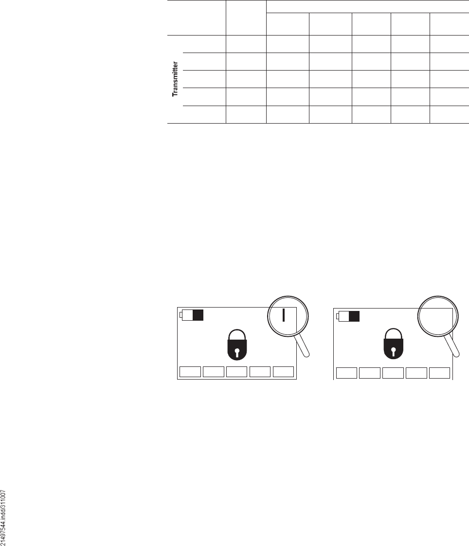
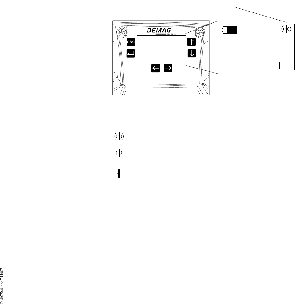
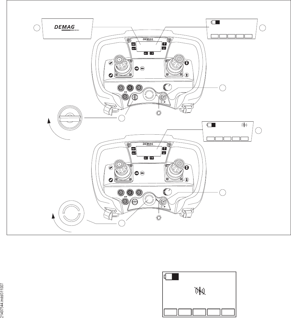
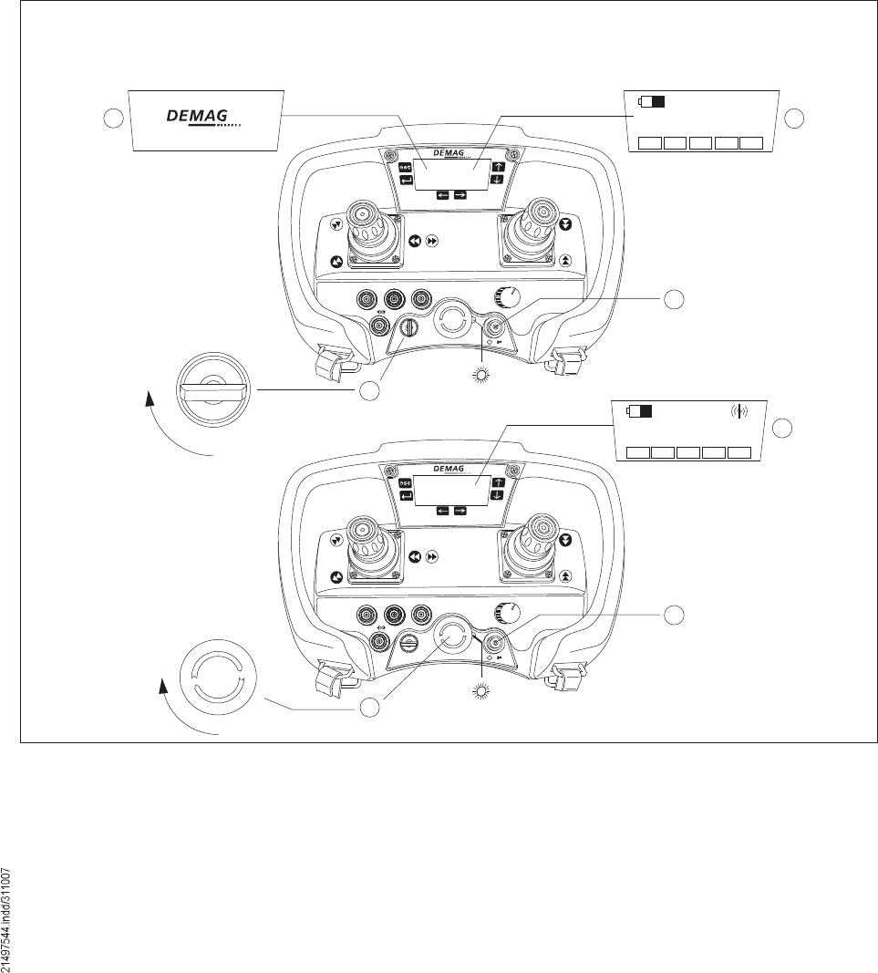
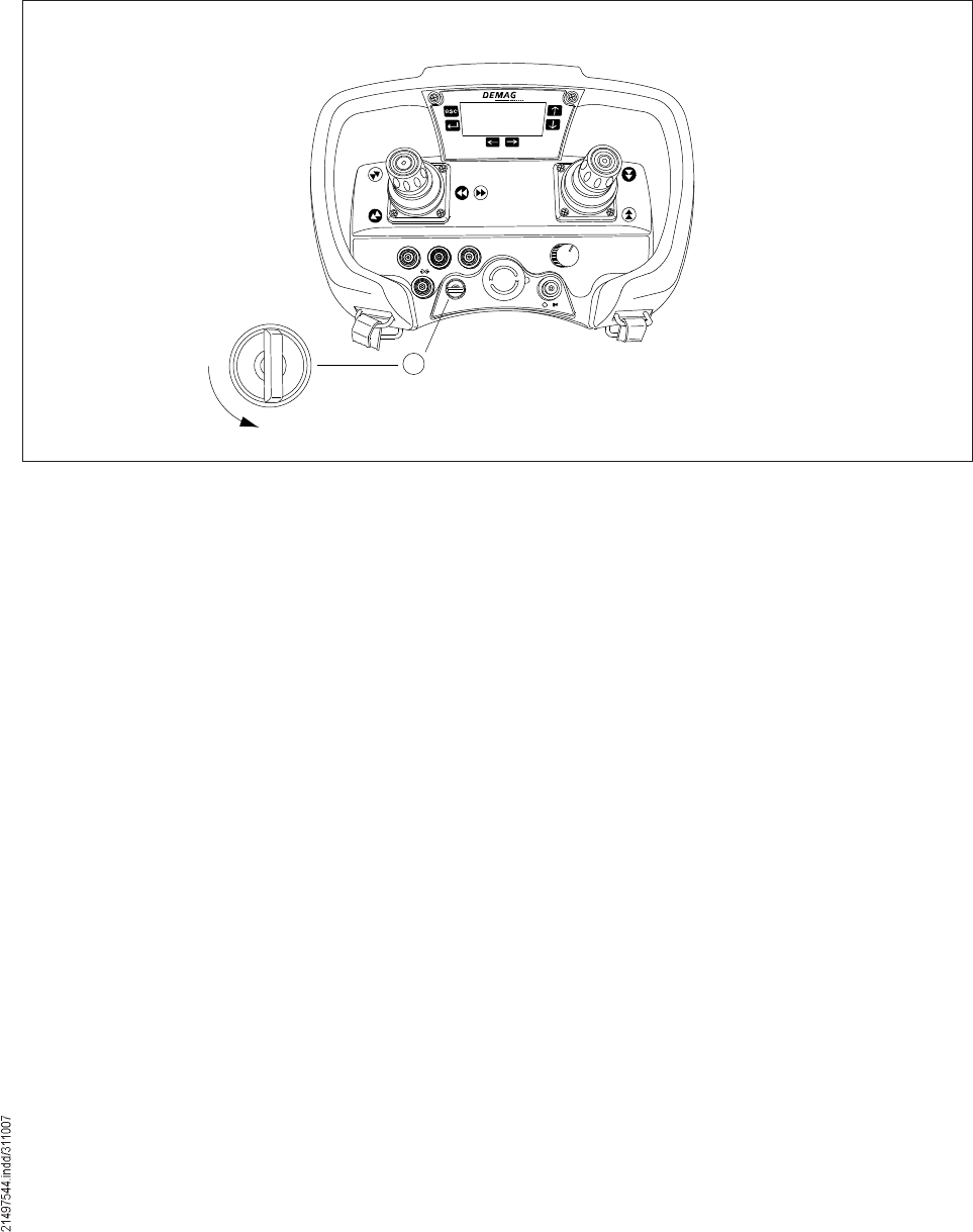
The LED in the joystick control system indicates the operating status of the joystick
control system:
LED Operating status
LED off The joystick control system is switched off or in standby
mode
LED lit red The joystick control system is in STOP mode
LED flashes green The joystick control system is in operating mode
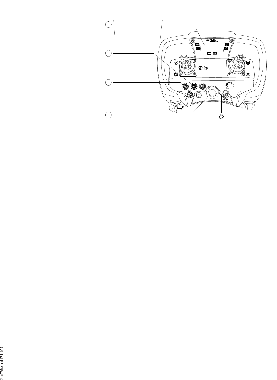
Display
STOP key
42680844.eps
LED
Travelling hoist
selector switch
Start / Horn key
Key-operated switch
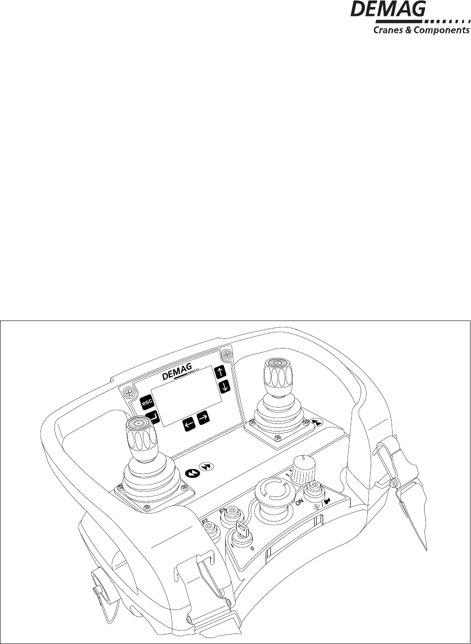
5 Identification and display functions
5.1 Joystick control unit
Úï Úî Úí ïïõî î
ÑÒ
×
ð ñ
×
42684444.eps
Yellow symbol against
black background
Black symbol
against yellow back-
ground
Yellow symbol
against black
background
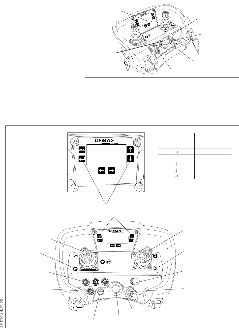
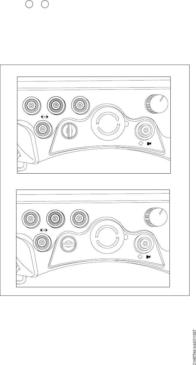
Key
Symbol Key
Designation
EscCancel
Right
Left
Up
Down
Return
STOP key
Key-operated switch
Switching on and off
Joystick
Lift/lower load
Joystick
Long travel forward/
backward
Cross travel left/right
1 key
Check limit switches
3 special function
keys (F1, F2, F3)
1 key
Horn / Start
(Switching on the
joystick control unit)
3-stage travelling
hoist selector switch
(1 or 1+2 or 2)
Red/green LED
42680944.eps
Key designation
16
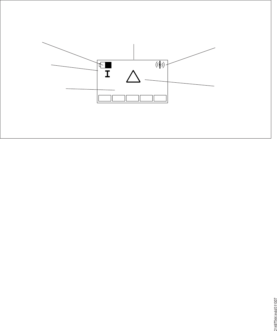
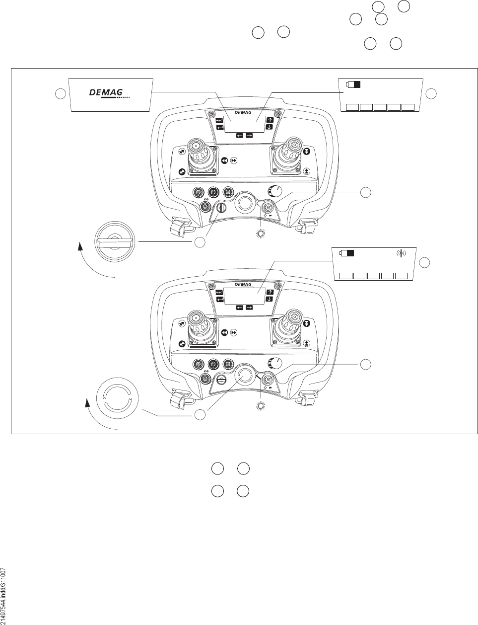
5.2 LCD display The joystick control unit is provided with a display. In the display, all data important
for operation of the crane to be operated are shown.
The number of information items displayed varies depending on the type of re-
ceiver. The scope of display functions comprises the general displays which are
available for both receiver types and additional information that can only be used
with DRC-DR receivers.
42694944.eps
Õëêì
ðððë
DRC-MP radio receiver display
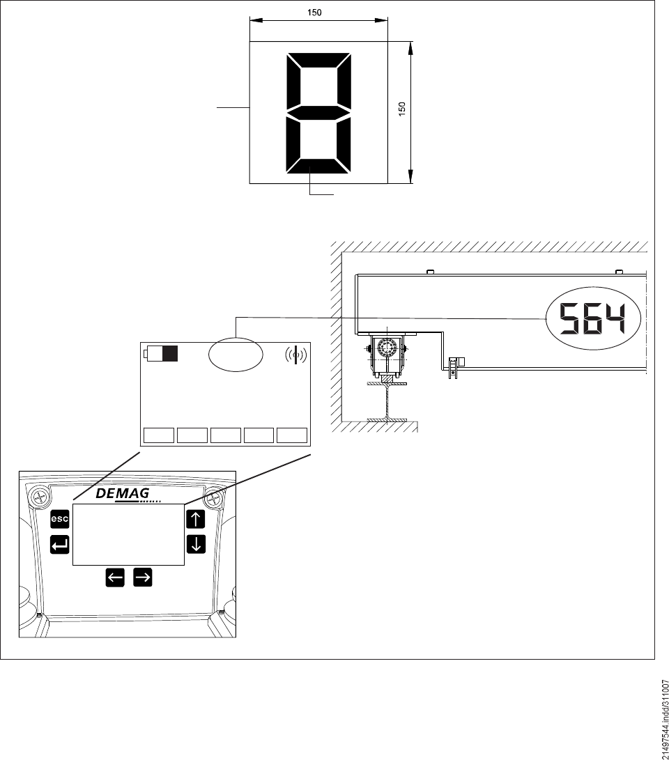
Battery capacity Crane identification Radio signal quality
1st main row with
large icon or numerical
display
Display of selected
travelling hoist(s)
2nd main row with alpha-
numerical display
17
Crane identification K564
The crane identification shows to which crane the joystick control unit has been
assigned. It is saved in the radio receiver and it can only be entered via the joystick
control unit.
Display of selected travelling hoist(s)
The display of the selected travelling hoists is only active, if there are two travelling
hoists and both can be operated with one radio control system.
Symbol Meaning
I Travelling hoist 1 is selected
II Travelling hoist 2 is selected
I+II Travelling hoists 1 and 2 are selected
Display of radio connection quality
5.2.1 General display
Symbol Meaning
Full signal strength
50 % of max. range between transmitter and receiver reached
Weak signal: If the distance between the transmitter and the
receiver is further increased, the radio connection may be
interrupted
42680944.eps
Signal strength icon
42696144.eps
18
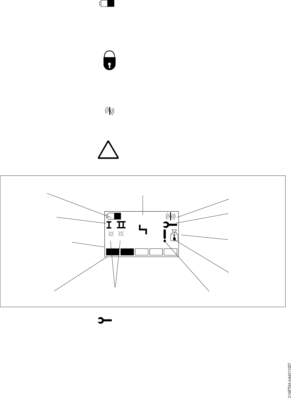
Õëêì
ðïìë
õ
Íî
Íï
Battery capacity Crane identification Radio signal quality
Display of service
interval
1. Main row with
large icon or
numerical display
Load-proportional bar
display
Display of selected
travelling hoist(s)
2. Main row with alpha-nu-
merical display
Icons for switching statuses of
universal outputs Safety function off icon
Load reduction icon
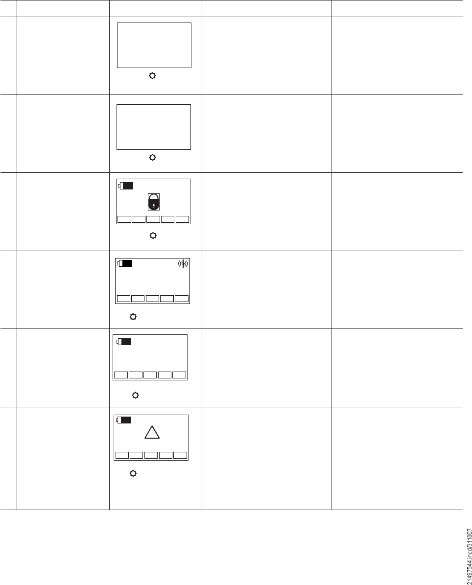
5.2.2 Additional display information
Display of service interval
This icon indicates that the Demag Service or a service company
authorized by Demag must be called in for service work.
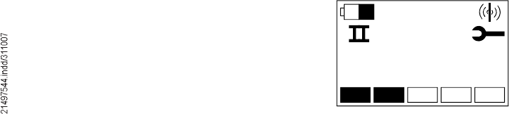
In the first main row, all icons important for operation are shown.Icons in the first main row
Battery icon
The battery icon indicates the status of the rechargeable batteries.
Lock icon
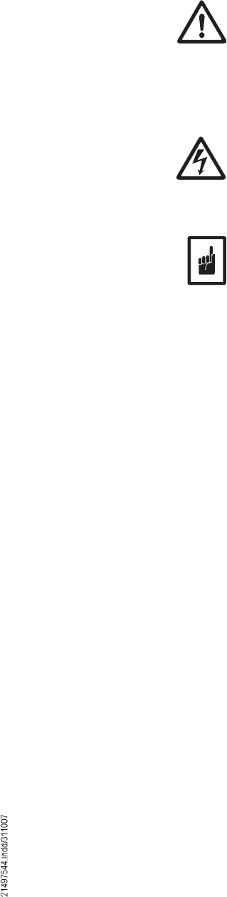
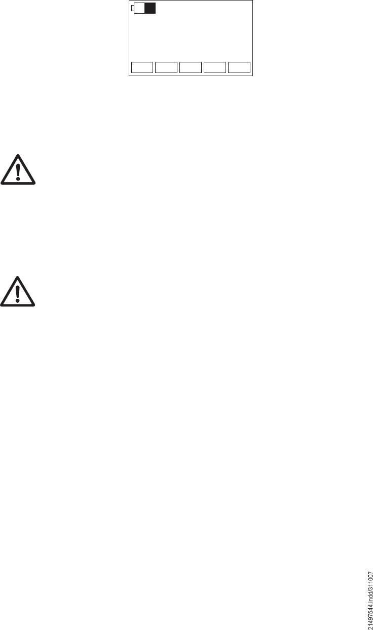
The lock icon indicates the standby mode. An electronic On key must
be entered to switch the unit on.
STOP icon
STOP indicates the STOP mode. The system switches over to Run
mode with the electronic key.
!No radio connection! icon
The "No radio connection" icon is displayed, if the joystick control unit
failed to establish a connection to the assigned radio receiver.
Warning icon
The warning icon is displayed in the event of a warning. The code of
the warning is displayed in the row below.
STOP
42694144.eps
DRC-DR radio receiver display
19
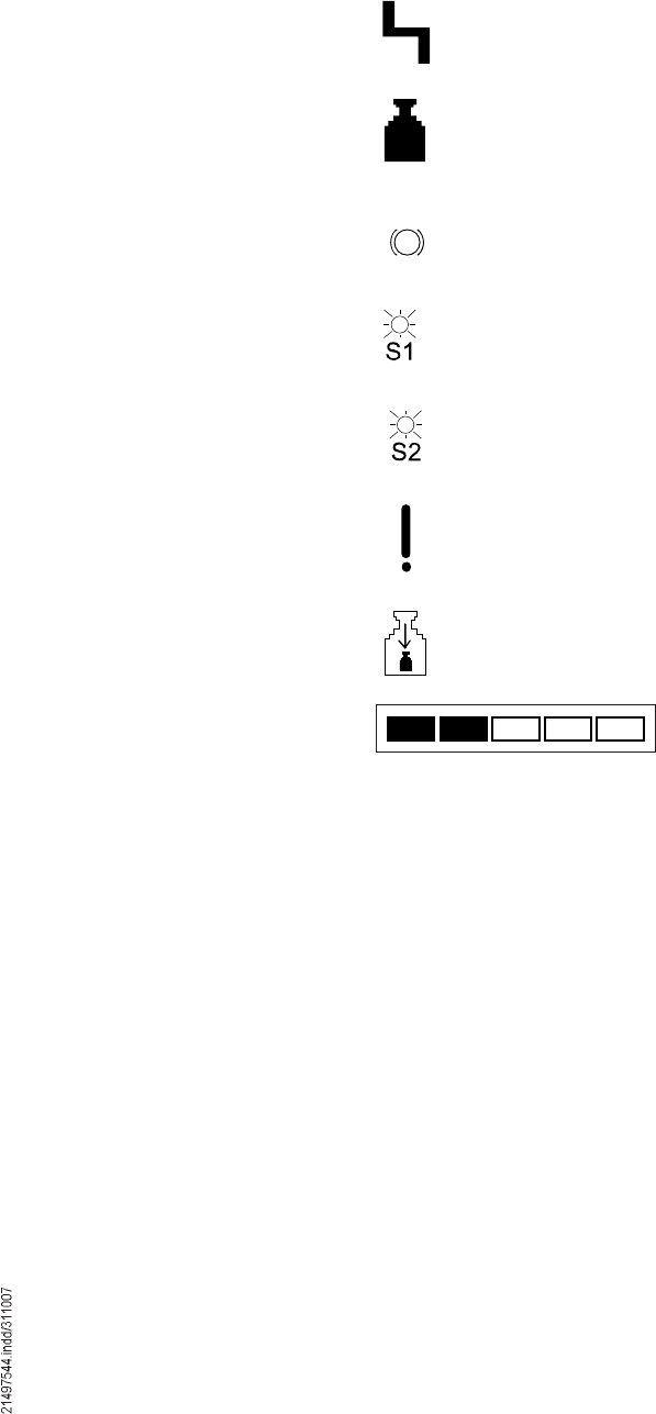
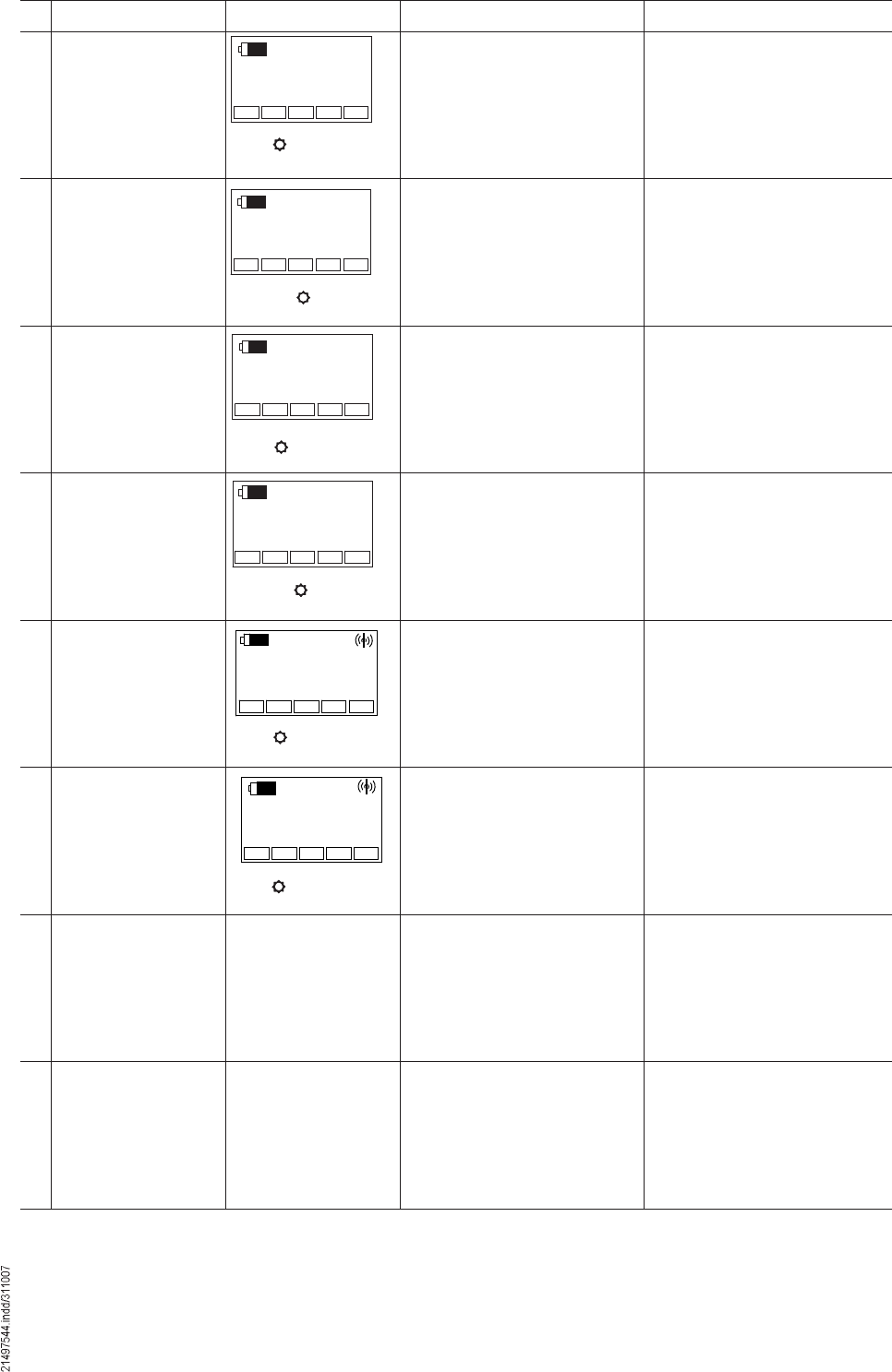
Fault icon
The fault icon is displayed in the event of a fault.
The code of the fault is displayed in the row below. If there are several
faults at the same time, the code displayed changes in cycles.
Overload icon
The overload icon is displayed in the event of an overload. The load of the
selected travelling hoist(s) is also displayed in the row below if the hoist is
fitted with ZMS.
Brake icon
The brake icon is displayed, if the additional brake has been applied.
"Universal output 1 switching status! icon
This icon is displayed when universal output 1 is active. The function of
this output can be programmed.
"Universal output 2 switching status! icon
This icon is displayed when universal output 2 is active. The function of
this output can be programmed.
"Attention! Safety function de-activated! icon
This icon indicates that a function relevant for safety such as load reduc-
tion or by-pass control has been de-activated by the operator.
"Load reduction active! icon
The icon indicates that load reduction is active. As long as load reduction
is active, only the reduced load (specified by a parameter) can be lifted.
The load-proportional bar display shows the load on the crane in five
increments of approx. 20 %. This display is independent of the travelling
hoist selection and always refers to the max. possible load.
Icons in the first main row
Load-proportional bar display
20
Õëêì
Every crane with wireless control must be identified by means of an easily visible
crane identification/number. Travel direction symbols on the crane and the travel-
ling hoist must identify the movement directions of the travel motions in line with
the identification of the keys on the joysticks of the joystick control unit.
The coding labels are used for illustration of the crane identification on the
travelling hoist or on the crane. The crane identification illustrated by means of
the coding labels must be identical with the crane identification shown in the
display of the DRC-J joystick control system.
5.3 Identification labels
for the crane
installation
5.3.1 Coding labels
42056044.eps
Yellow segment
Ident. no. 895 640 44
Black carrier foil
Ident. no. 895 639 44
42658944.eps
Display of crane identification on the joystick control unit Crane identification
The coding labels (dimensions 150 x 150 mm) (black background foil + foil with
number) must be fitted on the hoist unit in such a manner that they are easily
visible. Numbers 1 to 9 are produced by removing the yellow segments.
42680944.eps
42658955.eps

21
Cross-travel speed
Part no.: 895 635 44
Long-travel speed
Part no.: 895 637 44
5.3.2 Travel direction symbols
The direction labels must be fitted on the hoist unit in an easily visible manner,
matching the movement of the drive and in line with the direction symbols on the
joystick control unit.

22
A radio control system has been put into operation when the joystick control unit
has been put into operation. The following preparation measures are necessary:
The DRC-J joystick control system is already fitted with a rechargeable battery
when it is delivered.
Since the new rechargeable battery is only partially charged, it must be charged
before the unit is put into operation for the first time by placing it in the charger
(see section 8.3).
If no battery icon is displayed when the joystick control unit is activated,
the batteries are completely discharged. In this case, the battery must be
removed and charged in the external charger (see also chapter 8 #Joystick
control unit power supply").
Demag DRC-MP or DRC-DR radio receivers must be fitted in accordance with the
relevant operating instructions and connected in accordance with the circuit dia-
gram of the installation. Comply with the instructions and measures described in
the operating instructions for putting the radio receiver into operation.
A unique crane identification/number must be selected (recommended: a 3-figure
number) and fitted to the crane in accordance with section 5.3 for the crane fitted
with the radio control system.
6 Putting the radio control system into operation after
installation
6.1.1 Charging the batteries before
putting the unit into operation
for the first time
6.1.2 Assembly and connection
of the radio receiver
6.1.3 Applying the crane
identification on the crane
6.1 Putting into operation
23
6.2 Putting a radio remote
control system with
DRC-J into operation
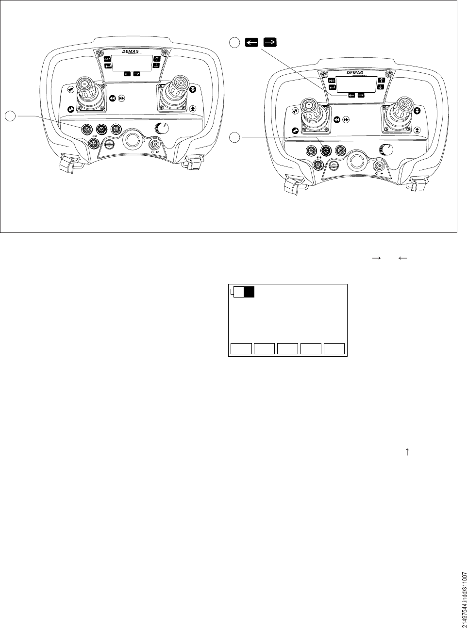
6.2.1 Switching on the joystick
control system
The DEMAG logo is displayed first. The DRC-J joystick control unit scans the radio
channels for controllable radio receivers and searches for an assigned radio re-
ceiver. Before the joystick control unit has been put into operation for the first time,
it has no radio receiver assigned, therefore you can expect the following display:
ÒÑ×Ü ááá
42694244.eps
ï
Úï Úî Úí ïïõî î
ÑÒ
×
ð ñ
×
í
î
ì
×
ð
Úï Úî Úí ïïõî î
ÑÒ
×
ð ñ
×
é
Õëêì
ê
ë
Õëêì
ͬ±°
ááá
Switching on the joystick control system
42684944.eps
Green
Press 1 x
Red
Press 1 x
Following these preparation measures, put the joystick control unit into operation
by logging it on to the radio receiver of the crane to be controlled. Following this
procedure, the radio control system is configured for the specific application.
The Demag DRC-MP or DRC-DR radio receiver on the crane must be supplied
with power, be ready for operation and within the range of the joystick control unit.
When the unit is switched off, there are no icons in the display, the LED is off. To
switch on the joystick control system, first move the key-operated switch to position
I and actuate the Start key. Then unlatch the STOP key and press the Start key
again.
24
If the transmitter has already been assigned to a receiver in the log-on steps as
described in section 6.2.2, you can expect the following display:
ÒÑ×Ü
ÍÌÑÐ
ááá
In this case, continue putting into operation with the assignment of the crane
identification, see section 6.2.3.
Note: Additional information may also be shown in the display depending on
the type of crane control system.
Logging on a joystick control system as described in the following is a safety-
relevant process that may only be carried out by authorized and instructed expert
personnel.
Important:
Each receiver is assigned a crane identification when it is put into service (see
section 6.2.3).
This crane identification must be shown in a clearly visible manner on the travel-
ling hoist or crane by means of coding labels. When a new joystick control unit is
logged on, the crane identification shown on the joystick control unit must match
the coding labels on the crane (see section 5.3).
Correct assignment between the transmitter and the crane must be checked by
actuating the horn before any crane motion is actuated.
If the correct assignment is not checked, unintended crane movements may cause
serious damage and injuries, even resulting in death.
Log-on of a DRC-J joystick control unit to a DRC-MP or DRC-DR radio receiver
establishes the assignment between the relevant joystick control unit, the control-
led radio receiver and the crane that is unique world-wide. The transmitter and the
receiver are provided with unique address features that are exchanged during the
log-on process and ensure clear and unique assignment. During the log-on steps,
the crane identification (see sections 5.3 and 6.2.2) is also transmitted from the
receiver to the joystick control unit and is saved. DRC-J joystick control units show
this crane identification/number so that the operating personnel can identify the
controlled crane.
Log-on is activated in Run mode or STOP mode.
6.2.2 Logging-on the joy-
stick control system
42694344.eps
25
Following activation, a two-digit number is shown in the first main row which in-
dicates the number of controllable radio receivers within the range (the example
shows controllable receiver 01).
This process may take several seconds.
Úï Úî Úí ïïõî î
ÑÒ
×
ð ñ
×
ðï
î
í
ï
ì
Searching and activating the menu
42685144.eps
Hold down once for approx.
5 seconds
Press 3 x
Press 1 x Green
26
Úï Úî Úí ïïõî î
ÑÒ
×
ð ñ
×
é
ï÷
ê
Úï Úî Úí ïïõî î
ÑÒ
×
ð ñ
×
ë
ðï
1) The transmitter shows the number of cranes which are in range and not assigned to a transmitter.
End search
Press 1 x
Select and confirm
42685244.eps
Confirm 1x
42685344.eps
Select crane/travelling hoist
Select radio receiver based on crane identification
After starting selection with F1, the crane identification of the controllable radio
receivers can be displayed one by one by scrolling with the and keys.
ÒÑ×Ü
ð ï
ÒÑ×Ü
By pressing the F2 key for confirmation, the joystick control unit is assigned to
the DRC-MP or DRC-DR radio receiver whose crane identification is shown in the
second main row of the display (NOID in the example). At the same time, the crane
identification of the DRC-J joystick control unit is also changed to the new value
and displayed next to the battery icon.
Log-on of the joystick control unit is then completed by actuating the key.
Note: Log-on of the DRC-J joystick control unit to a DRC-MP or DRC-DR
radio receiver with code NOID is only necessary when the unit is put
into operation for the first time in order to assign the crane identification
determined in section 6.2.3 to the receiver.
42694444.eps
27
ÒÑ×Ü
ððïæ
ððð
Important! The assignment of the crane identification described in the following
for putting the radio receiver into operation is a safety-relevant
process that may only be carried out by authorized expert personnel.
After successful establishment of a radio connection between the DRC-J joystick
control unit and the DRC-MP or DRC-DR radio receiver, the crane identification
determined acc. to section 5.3 must be assigned to the radio receiver. As long as
the radio receiver operates with code !NOID", no movement commands are output
to the crane control system. (To check radio transmission in this status, use the
signal key if Run mode has been activated.)
Activating the assignment
Assignment is activated in STOP mode or Run mode.
Actuate the STOP key
Actuate key
Actuate the key twice
Hold down the key for 5 seconds until the display changes
Release the key
The following display appears
6.2.3 Assignment of the crane
identification/number for
the radio receiver
Note: Additional information may also be shown in the display depending on
the type of crane control system.
The code no. of the displayed parameter is shown in the first main row.
The value of the parameter is shown in the second main row.
Selection of parameter 004 for the crane identification/number
42694544.eps
42680944.eps
Key increases the displayed parameter code no.
$ Key decreases the displayed parameter code no.
28
ÒÑ×Ü
ó ó ó ó
42694644.eps
Entry of the crane identification/number
First select parameter 004, then actuate the F1 key to start entry. The following
display appears
Four free digits for entry of the crane identification/number are highlighted in the
first main row. The first digit is preselected. Use the and keys to select a
number/character from the available set of characters. Press the F1 key to accept
the selected character and to change to the next position.
Transmitting the assigned crane identification
When the appropriate crane identification has been entered, press the F2 key to
confirm and to transmit it to the crane receiver. This crane identification is then
saved in the radio receiver. The joystick control unit will keep and display its old
crane identification (NOID) until the joystick control unit has been logged on as
described in 6.2.2 for the radio receiver with the new crane identification.
6.3 Configuration of a
radio remote control
system for DRC-DR
ÒÑ×Ü
ÍÌÑÐ
ááá
42694344.eps
Cancelling/ending assignment of the crane identification
The entry can be cancelled at any time without changing the crane identification by
actuating the key. Entry is completed by actuating the F2 key. Then use the key
to exit the assignment menu.
Important! After changing the crane identification for the receiver, log-on
of the joystick control unit must always be carried out (section 6.2.2) so
that the new crane identification is displayed on the joystick control unit.
DR cranes that are provided with the DRC-DR radio receiver use an extended
scope of functions of the DRC-J joystick control system for configuration of the
crane control system and to display information. Additional instructions and infor-
mation are described in the operating instructions of the Demag DRC-DR radio
receiver (ident. no. 214 953 44) for putting a crane with the DRC-DR radio receiver
into operation.
29
The operator controls the radio-controlled crane by means of the DRC-J joystick
control unit.
Before starting work, the operator must carry out the inspections and function
checks listed in the crane operating instructions and must be satisfied that the
installation is in safe operating condition.
When the unit is switched off, there are no icons in the display, the LED is off. To
switch on the joystick control system, first move the key-operated switch to position
I and actuate the Start key. Then unlatch the STOP key and press the Start key
again.
7 Operation of the radio control system
7.1 Checks before starting
work
7.1.1 Switching on the joystick
control system when starting
work
ï
Úï Úî Úí ïïõî î
ÑÒ
×
ð ñ
×
í
î
ì
×
ð
Úï Úî Úí ïïõî î
ÑÒ
×
ð ñ
×
é
Õëêì
ê
ë
Õëêì
ͬ±°
ááá
Switching on the joystick control system
42684944.eps
Green
Press 1 x
Red
Press 1 x
30
The DEMAG logo is displayed first. When the connection to the radio receiver has
been established, the following displays must be shown:
Crane identification of the assigned radio receiver
Icon to display the radio signal quality
Icon to display the battery capacity
Bar display
Stop
Õëêì
ͬ±°
ááá
42660044.eps
The radio system performs a self-test when it is switched on. The installation is
then ready for operation if no error statuses are displayed. Fault elimination is
described in chapter 11.
In addition, the crane operator must check the following before starting work:
Battery capacity 8.2
Quality of radio connection 5.2.1
Displayed crane identification and relevant crane 5.2.1
Function of signal/horn 5.1
STOP key function 2.7
To check functioning of Signal and STOP, crane operation must be switched on.
7.1.2 Checking the radio system
31
The LED in the display field flashes green if Run mode is switched on after entry.
Sequence 1 to 4 causes the control system to be switched on and a radio
connection to be established with a receiver in STOP mode.
Sequence 5 to 7 switches the system to Crane operation/Run mode.
Run mode of the radio system must be started for crane operation. To do this, the
On key must be entered. The system switches over to Run/Crane operation mode
by means of the On key:
when the joystick control unit is switched off (steps 1 to 7 )
from Standby when STOP is actuated (steps 2 to 7 )
from STOP (steps 5 to 7 )
from Standby when STOP is not actuated (steps 6 to 7 )
7.2 Crane operation/Run
7.2.1 On key
ï
Úï Úî Úí ïïõî î
ÑÒ
×
ð ñ
×
í
î
ì
×
ð
Úï Úî Úí ïïõî î
ÑÒ
×
ð ñ
×
é
Õëêì
ê
ë
Õëêì
ͬ±°
ááá
42684944.eps
Green
Press 1 x
Red
Press 1 x

32
In Run mode, the crane (hoist, cross travel, long travel) can be controlled with both
self-centering operating levers (see figure in section 5.1).
Lever actuation is stepless after the switch-on threshold to enable control of
switched or speed-controlled drives, depending on the design of the crane control
system.
The STOP key identified in red results in a STOP command which stops the
movements of hoist, cross travel and long travel at the same time and triggers an
emergency-stop in the crane control system.
To avoid danger, the crane operator can immediately stop all movements by
means of the STOP key. The braking process caused by an EMERGENCY stop
can result in load sway.
The STOP key is also intended to be used for switching the radio-controlled crane
into a safe status. This method is to be used when interrupting work for longer
periods and for starting additional functions of the joystick control unit for display-
ing information and servicing purposes.
When STOP has been actuated, crane operation can only be re-activated by
unlatching the STOP button and actuating the Start key.
The Start/Signal key is of single-stage self-resetting design. It simultaneously
activates the Start and the Horn signal.
The function keys are of single-stage self-resetting design. Various additional
functions are controlled depending on the design of the radio receiver and the
crane control system. These functions are described in the operating instructions
of the receiver or the crane installation.
The check limit switch key is of self-resetting design. It activates an additional
signal for the crane control system to test the hoist limit switch function. Refer to
relevant guidelines and regulations for radio-controlled cranes for instructions on
use.
7.2.2 Functions in crane operation
7.2.3 STOP function
7.2.4 Start/Signal key
7.2.5 F1, F2 and F3 function keys
7.2.6 Check limit switch key
33
At the end of the shift or in the event of longer breaks, DRC-J joystick control units
must be switched off by means of the key-operated switch to protect the instal-
lation against unauthorized use and to reduce power consumption of the DRC-J
joystick control unit.
7.3 Taking out of service
at the end of the shift
7.4 Operating statuses
of the radio control
system
The function and display of the radio control system are determined by the operat-
ing status of the joystick control unit. The operating status of the joystick control
unit is transmitted to the crane control system.
Display and radio connection are de-activated. Power consumption of the joystick
control unit in this status is less than the natural discharge of the battery.
When the STOP button is latched, the joystick control system is in STOP mode,
the LED is permanently lit red.
The display shows STOP. No travel commands are transmitted in STOP mode.
The EMERGENCY stop contact in the receiver (crane switch for DRC-DR) is open.
The radio connection to the receiver is maintained. Following a timeout period
of 5 minutes without any key actuation, the joystick control unit will automatically
switch to Standby mode.
The LED in the keyboard flashes green. The crane identification of the assigned
crane and the icon for the radio connection are shown in the display. In Run mode,
the joystick control unit is fully functional for crane operation, see section 7.2.
Crane operation can be started with the On key in !STOP" and !Standby" mode,
see section 7.2.1.
Following a timeout period of 30 minutes without any key actuation, the joystick
control unit will automatically switch to Standby mode.
7.4.1 Joystick control system
switched off
7.4.2 STOP mode
7.4.3 Run mode
ï
Úï Úî Úí ïïõî î
ÑÒ
×
ð ñ
×
×
ð
Switching the transmitter off
42685044.eps
34
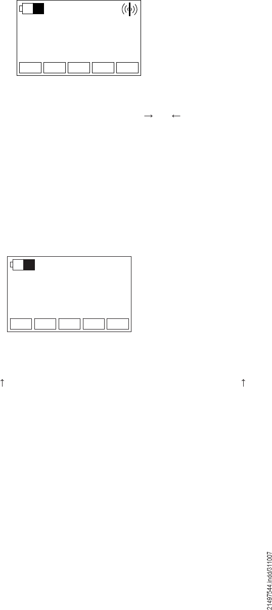
The display shows the lock icon. No radio connection is displayed. In standby
mode, power consumption of the transmitter is strongly reduced and the radio
connection is de-activated.
Standby is automatically switched on by the timeout function as described in
sections 7.4.2 and 7.4.3.
The operator can end Standby mode only by actuating the Start key, section 7.2.1,
sequence 5 to 7 and then change to Run mode.
A reset of the joystick control system may become necessary in the case of error
statuses of the software.
The joystick control system can be reset by switching it off by means of the key-
operated switch (reset).
7.4.4 Standby mode
7.4.5 Resetting the joystick control
42681144.eps
Úï Úî Úí ïïõî î
ÑÒ
×
ð ñ
×
Úï Úî Úí ïïõî î
ÑÒ
×
ñ
×
ð
42681244.eps
35
8 Joystick control unit power supply
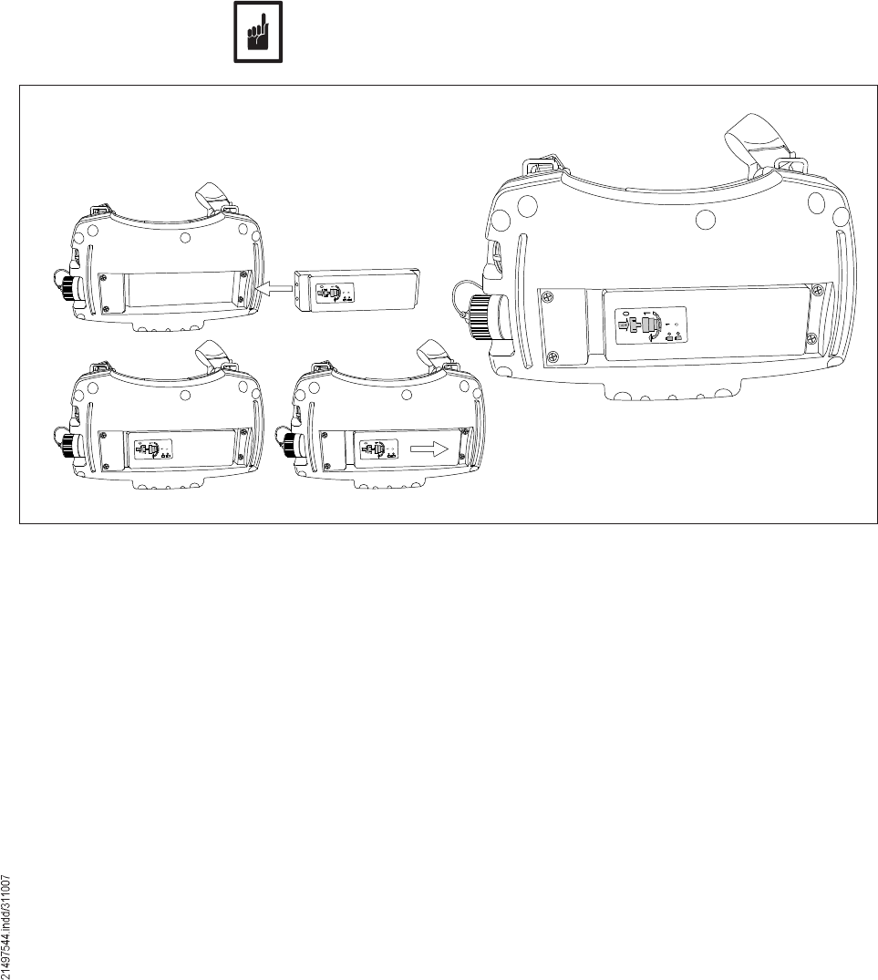
8.1 General description The joystick control unit is supplied with power from a rechargeable battery on the
underside of the unit (see section 8.4). A discharged rechargeable battery must be
removed from the unit and replaced with a charged battery taken from the charger.
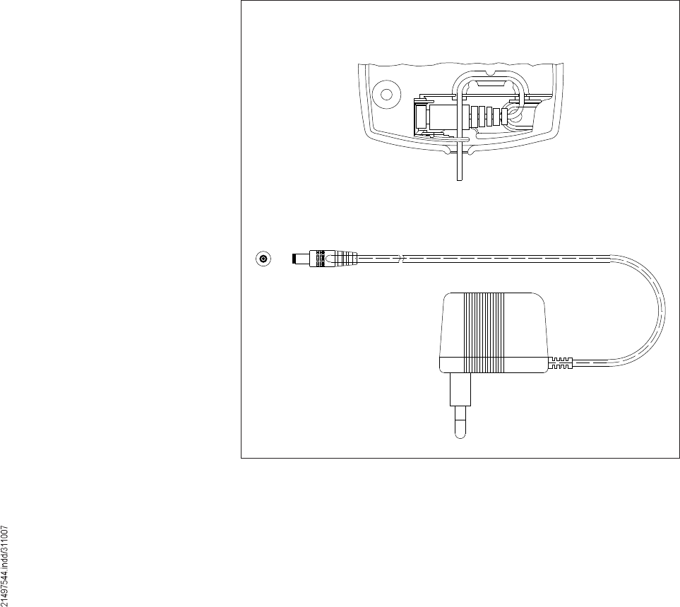
The charger consists of a charging socket (where the appropriate batteries are
inserted) and a pluggable power supply unit.
Connect the pluggable power supply unit to the charging socket as described
below.
At the beginning, the charger will charge the battery with a high current, the
charging current will then be reduced to trickle charging until the battery is
removed.
The normal charging time to charge a completely discharged battery is approx.
3 hours.
The charger has been designed so that the battery will not be damaged even if it
remains in the charger for a long time.
The charger must be installed at a vibration-free location (inside an enclosed
room), it must be protected against humidity, direct radiation from the sun and
large changes in temperature.
Permissible temperature range 10 % 45 °C for charging the batteries.
Connect the connector and fix the cable as described (strain relief)
Installation:
The battery charger starts a charging cycle as soon as a battery is inserted. (Green
LED starts flashing) After approx. 3 hours, the battery is completely charged and
ready for operation (green LED is now permanently on).
If the power supply to the battery charger is interrupted, the charger remembers
the charging status when it is switched on again % accordingly the rapid charging
mode or the trickle charging mode is continued when the unit is switched on again.
After 3 hours, rapid charging is stopped as a safety function % regardless of
whether the battery is fully charged or not. The green LED is then continuously lit.
42682544.eps
42682644.eps
Battery charger connection
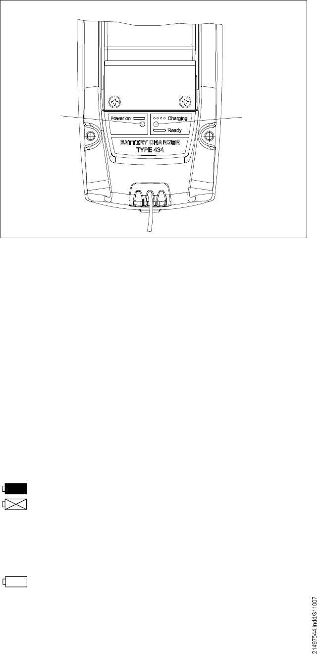
36
Red LED: Indicates power supply
Green LED: Indicates charging status
Green LED flashes: Battery is being charged (rapid charg-
ing)
Green LED permanently on: Battery charged; charger charges in
trickle charging mode
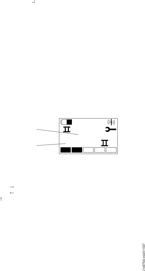
The battery capacity is shown in the display of the joystick control unit. The
charging status of the battery corresponds to the filled surface in the battery icon.
For a new battery, the completely filled battery icon means a useful operating time
of the switched-on joystick control unit (Run or STOP) of at least 8 hours.
If only residual charge is displayed, connect the joystick control unit to the charger
as soon as possible. If the battery icon is empty, the battery must be charged
immediately.
The operating time that can be reached for the joystick control unit with one battery
charge depends on the operating mode of the joystick control unit, the ambient
temperature and the age of the batteries.
If the joystick control unit is continuously switched on, 12 hours of operation can be
achieved with one battery charge.
Power consumption can be reduced by switching the joystick control unit off during
longer breaks in operation.
Charged battery icon
Icon for battery errors.
This icon appears, if a battery problem has occurred, e.g.:
- the battery is defective,
- the battery is too old,
A defective battery must be replaced by a new one (see section 8.4).
When the battery icon is displayed, immediately charge the removable
battery by means of the charger included in the supply.
If the battery is not charged immediately, the battery icon starts to flash
and the joystick control unit is switched off after a few seconds.
The charging process is monitored and controlled by the electronics in the joystick
control unit. A partly discharged battery can also be charged.
8.2 Display of available
battery capacity
8.3 Charging the battery
Red LED Green LED
42682344.eps
LED indicators on battery charger
37
The rechargeable battery in the joystick control unit will age as a consequence of
charging/discharging cycles and continuously loses charging capacity. We recom-
mend that the rechargeable battery be replaced after one year, at the latest. A
rechargeable battery must immediately be replaced if the relevant icon for a failure
in the battery is displayed.
The rechargeable battery supplied with the joystick control unit has been specifi-
cally selected for the requirements of this radio control system. The electrical and
mechanical features of the joystick control unit and rechargeable battery have
been matched to fulfill all requirements of trouble-free and safe operation.
For replacement, use the specified rechargeable battery, part no. 773 462 44. The
use of a non-approved rechargeable battery may result in joystick control unit op-
erating malfunctions or lasting damage to the charger and the joystick control unit.
Used rechargeable batteries must be disposed of in accordance with environmen-
tal protection regulations.
8.4 Replacing the battery
42680744.eps 42680644.eps
38
9 Information menu in connection with DRC-DR
This additional function of the joystick control unit can only be used in connection
with a DR rope hoist and CAN bus.
The Information menu makes the display of information on the crane or the travel-
ling hoist(s) possible. This information is stored in the form of a list by each DR
control system. One element of this list is requested by the joystick control system
and made available by the selected control system via the CAN bus.
Actuate the STOP key
Actuate theReturn key three times
The key sequence to activate the Information menu can be cancelled by actuating
the Esc key at any time.
Selection of the polled control system is analogue to travelling hoist selection.
Since the travelling hoist selection key has no function in the information menu,
the travelling hoist must first be selected in the Run operating mode:
Travelling hoist selection Information from
I Travelling hoist 1 control system
II Travelling hoist 2 control system
I+II Crane control system
After changing to the Information menu, the starting screen of the Information
menu is shown in the display of the joystick control unit. This starting screen shows
information START II (since travelling hoist 2 has been selected) and code 888:
9.1 Activating the
Information menu
9.2 Selecting the
information source
9.3 Starting screen
9.4 Navigating in the
information menu
Õëêì
ÍÌßÎÌ
èèèæ
Information code
Information
(Start info travelling
hoist II)
42660744.eps
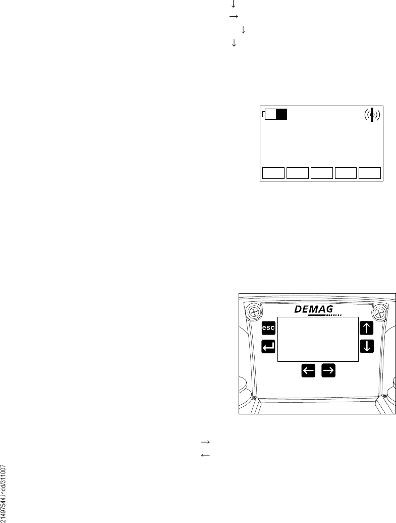
To navigate in the information list, use the following operating elements:
Operating element Function
Joystick to the next value in the list
Joystick back to the previous value in the list
Key exit the Information menu
39
The following data can be displayed via the Information menu:
Code Information
401 Remaining duration of service in % (determined from load spectrum)
400 Operating hours
000 Permissible full load hours acc. to FEM classification
001 Gearbox transmission ratio
002 Drum diameter
003 Reeving factor
004 Control type (travelling hoist or crane control)
005 Solo travelling hoist (with/without crane control)
146 Customer number
147 Order number
148 Serial number
149 Year of manufacture
150 Hoist speed V1
151 Hoist speed V2
152 Lifting height
153 Reeving
155 Rope diameter
171 Country code
216 Serial number of control system
217 Hardware version
520 Software version of main controller
529 Software version of monitoring controller
The following additional information is available with the "board computer!
option:
Code Information
402 K1 switching operations
403 Hoist brake switching operations
404 Travel path in m
405 K2 switching operations
406 K3 switching operations
416 Number of times slip limit is exceeded
417 Number of times the maximum speed is exceeded
418 Number of hoist brake errors
419 Number of times the overspeed brake is triggered
420 Number of overloads
421 Number of emergency stop actuations during motion of min. one
axis
448 Last occurring error
449 Last but one occurring error
Sequence and quantity of information depend on the software and may be
changed.
The following example shows the remaining duration of service:
9.5 Data of the
Information menu
Õëêì
ïìòêû
ìðïæ
42660844.eps
40
10 Technical data
DRC-J joystick control system
Operating elements 1 STOP key
1 joystick for the lifting/lowering axis
1 joystick for the 2 axes (cross and long-travel)
1 mechanical key-operated switch to switch the transmitter on and off
1 Horn / start key (to switch the joystick control system on)
1 check limit switch key
3 special function keys (F1, F2 and F3)
1 mechanical 3-stage selector switch (1 or 1+2 or 2)
Display with keys for menu navigation
Frequency range: 433.100 to 434.750 MHz
Transmitter power max. 10 mW ERP
Typ. range approx. 100 m
Type of enclosure: IP 55
Temperature range: -20 to +70 °C, at temperatures below 0 °C battery performance decreases. The
LCD responds slowly.
Operating time
with fully charged battery: approx. 8 h
Weight
incl. re-chargeable battery: 1, 8 kg
without rechargeable battery: 1, 6 kg
DRC-J charger
with suitable pluggable power supply unit: 110 / 230 V AC 50/60 Hz
Rechargeable battery
Battery type: NiMH, 7,2 V, 1600 mAh
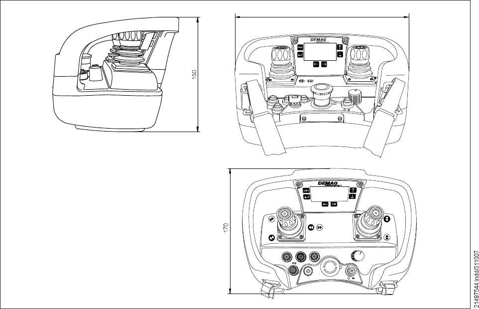
10.1 Dimensions
DRC-J joystick control system
42681344.eps
42682744.eps
42682844.eps
× ñð
Ѳ
îëð
Úï Úî Úí
×
ð
ïïõî î
ÑÒ
× ñ

41
10.2 International postal
registration
CountriesFrequency range
Australia433-MHz ISM band
Belgium433-MHz ISM band
Denmark433-MHz ISM band
UK433-MHz ISM band
Estonia433-MHz ISM band
Finland433-MHz ISM band
France433-MHz ISM band
Greece433-MHz ISM band
Holland433-MHz ISM band
Ireland433-MHz ISM band
Iceland 433-MHz ISM band
Italy433-MHz ISM band
Croatia433-MHz ISM band
Norway433-MHz ISM band
New Zeeland433-MHz ISM band
Poland433-MHz ISM band
Portugal433-MHz ISM band
Switzerland433-MHz ISM band
Slovakia433-MHz ISM band
Slovania433-MHz ISM band
Spain433-MHz ISM band
Sweden433-MHz ISM band
Czech Republic433-MHz ISM band
Germany433-MHz ISM band
Hungary433-MHz ISM band
Austria433-MHz ISM band
In the following countries, transmitters and radio receivers of the DRC-J D2 range
in the standard delivery form (part no.: 773 591 44) can be operated without any
registration or operating fee:
On request, the relevant approvals and/or certificates are available.
Operation in the following countries requires special approvals (e.g. import license)
Russia, Singapore, South Africa, Corea
Please contact the manufacturer, if use of the product is planned in the countries
mentioned above.
42
Before eliminating faults by measures on the radio control system, check that the
crane installation is supplied with power and is ready for operation and has not
been switched off by safety devices. (Mains connection switch, crane isolating
switch, STOP switch, travel and lifting path limitation devices, overload protective
device, motor protective switch, etc.)
11 Eliminating faults
No.ProblemIndicatorsPossible causesNotes, section in this document
01 Joystick control unit
cannot be switched
on with key-operated
switch
Power supply of the joystick
control unit has failed
Check rechargeable batteries,
see section 8.
Replace completely discharged
batteries.
02 Joystick control unit
cannot be switched
on with key-operated
switch Joystick control unit has failedReplace joystick control unit
03 Joystick control unit
cannot be switched on
with On key Standby mode with latched STOP
key Unlatch STOP key
04 Crane does not respond
to key command Assignment of crane identi cation
is missing Horn is working;
Assign crane identi cation, 6.2.3
05 Crane does not respond
to key command Assigned crane receiver has no
power supply Switch on crane; check cra-
ne receiver acc. to operating
instructions
06 Warning during start of
crane operation
Re-establishing radio connection
after:
- Malfunction in DRC-MP receiver
- Timeout of joystick control
system
- Range limits exceeded or Auto-
power-off
- Power-Down: Short-term under-
voltage or voltage failure on the
receiver side.
- After log-on of a new transmitter
Acknowledge warning with
STOP key. Restart with On key
7.2.1
Õïîí ááá
ÒÑ×Ü
Õïîí ááá
Õïîí
ðçççç
ááá
LED Off
LED Off
LED Off
LED Green, flashes
LED Green, flashes
LED Green, flashes
1)
1)
1)
1)
43
No.ProblemIndicatorsPossible causesNotes, section in this document
07 The displayed crane
does not respond Another joystick control unit has
been logged on for the crane
Take the other joystick control unit
out of service, 7.3
Log-on joystick control unit again,
6.2.2
08 The displayed crane
does not respond Power supply of receiver
interrupted Actuate and release the STOP key,
then enter the On key, 7.2.1
No. 06 or 10 is then possible
09 The displayed crane
does not respond Crane receiver outside range
of transmitter
Reduce distance to crane, 2.7
and 5.2.1 Check radio reception
by means of log-on procedure
6.2.2. Check aerial connector
on receiver.
10 Crane does not respond
to key command STOP modeEnter On key, 7.2.1.
11 The crane identi cation
displayed on the joystick
control unit is incorrect
The crane identi cation of the
receiver was changed with the
joystick control unit
Safety problem!
A crane that is not displayed is
being controlled. Actuate signal to
identify the crane. Log-on joystick
control unit, 6.2.2
12 The crane identi cation
is missing in the display The crane identi cation of the
receiver was changed with the
joystick control unit
Safety problem!
A crane that is not displayed is
being controlled. Actuate signal to
identify the crane. Log-on joystick
control unit, 6.2.2
13 Joystick control unit
does not respond to
key commands Any malfunctioning
display Software crash Reset joystick control unit, 7.4.5.
Then switch on with key-operated
switch.
14 Operating time
with fully charged
battery too short
Battery display changes
to uncharged within a
short time.
Charging procedure aborted.
The battery is used/too old.
Ambient temperature below
10 °C during charging
Repeat charging procedure, 8.1.
and 8.4.
1) Additional symbols in the display eld are possible
Õïîí ááá
Õïîí ááá
Õïîí
ͬ±°
ááá
ÒÑ×Ü
1)
1)
1)
1)
1)
1)
LED Green, flashes
LED Red
LED Green, flashes
LED Green, flashes
LED Red
LED Green, flashes
Õïîí
ááá
If application of the above instructions does not result in elimination of the fault,
please contact Demag customer service.
44
# = Modi cations compared
to previous issue Class. no.715 IS 975
205 331 44
Normung DCC
ppa. Gersemsky ppa. Hoffmann
Technik Handling Technology BU Handling Technology
Page 1 1 page(s)
EN
Issue 0107
Ident. no.
EC conformity declaration
Demag radio control system
in accordance with EC directive 89/336/EEC, Appendix I, 73/23/EEC,
Appendix III and 99/5/EC
Reproduction in whole or in part only with prior consent of Demag Cranes & Components GmbH, D-58286 Wetter Subject to change. Not liable for errors or omissions.
#
1) Application of CE symbol in accordance with EC Low Voltage Directive 2006/95/EC:
RC-10 1998; RC-J 2000; DRC-10 2004; DRC-J 2004; DRC MP 2005; DRC-DR 2005; DRC-DC 2006.
#
#
#
#
Hereby we,
Demag Cranes & Components GmbH
declare that the product
Demag radio control system RC-10, RC-J,
DRC-10, DRC-J,
DRC-MP, DRC-DR, DRC-DC 1)
of serial design is in conformity with the provisions of following relevant regulations:
EC EMC directive 89/336/EEC
amended by 92/31/EEC and 93/68/EEC
EC Low voltage Directive 2006/95/EC
EC radio and TTE directive 99/ 5/EG
Applied harmonised standards:
EN 954-1 Safety related parts of control systems
EN 13557 Control elements and control positions
EN 50178 Electronic equipment for use in electrical power
installations and their assembly into electrical power
installations
EN 60204-32 Electrical equipment, requirements for hoists
EN 60529 Types of enclosure (IP code)
EN 61000-6-2 Electromagnetic compatibility $ Immunity for industrial
environments
EN 61000-6-4 Electromagnetic compatibility $ Emission standard for
industrial environments
EN 300220-3 Electromagnetic compatibility and Radio spectrum
Matters (ERM); Short Range Devices (SRD)
Wetter, 16 January 2007
Place and date of issue
45
Operating instructions
DRC-J joystick control system parameter programming
(For authorized personnel only)
Note:
Parameters 007 and 008 will only be available from the D2 generation of units on (presumably from
October 2007 on).
Joystick transmitters with part no. 773 460 44 form part of the D1 generation of units and thus do not fulfil
the parameters 007 and 008 described!
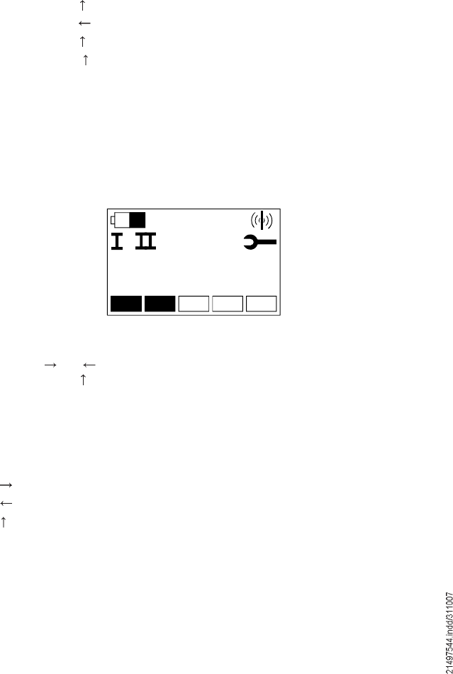
46
The !joystick control system parameter programming" menu can be used by
specially trained personnel for displaying and partly changing the following settings
of the joystick control unit:
Code Information
001 Displaying the serial number of the joystick control system
002 Displaying the software version of the joystick control system
003 Displaying the hardware version of the joystick control system
004 Displaying and entering a fixed frequency channel (channel lock)
005 Displaying and entering the cut-out time in STOP mode
006 Displaying and entering the cut-out time in Run mode
Note: Parameters 004 to 008 are set in the factory and must not be changed with-
out prior agreement.
Attention: Changes to the parameters of the joystick control system may impair
functioning of the hoist unit.
The menu is activated in Run mode or STOP mode.
Actuate the STOP key
Actuate the key
Actuate the key twice
Actuate the key again and hold it down for approx. 5 seconds
Release the key again
Every change to the !joystick control system parameter programming! menu is
signalled to the crane control system.
The key sequence to activate the menu can be cancelled by actuating the Esc key
at any time.
Only parameters are first displayed after activation of the menu. The display starts
with parameter 001, i.e. the serial number of the joystick control system:
1 Menu for programming parameters of the joystick control
system
1.1 Activating the menu
1.2 Displaying the current
parameters
Õëêì
ðððêêïìë
ððïæ
õ
Use the and keys to select the parameter to be displayed. The menu can be
exited with the key at any time.
The serial number of the joystick control system is displayed with parameter 001. It
is only provided for information and cannot be changed. To navigate, use the fol-
lowing keys:
Key Function
Change to display of parameter 002
Change to display of parameter 008
Exit menu
1.3 Displaying the serial
number of the joystick
control system,
Parameter code 001
42694744.eps

47
The software version number of the joystick control system is displayed with
parameter 002. It is only provided for information and cannot be changed. To
navigate, use the following keys:
Key Function
Change to display of parameter 003
Change to display of parameter 001
Exit menu
The hardware version number of the joystick control system is displayed with
parameter 003. It is only provided for information and cannot be changed. To
navigate, use the following keys:
Key Function
Change to display of parameter 004
Change to display of parameter 002
Exit menu
This parameter makes it possible to determine the channel used by the radio
control system and, therefore, the frequencies used. If a channel is selected, the
radio control system uses it instead of searching for a free channel to establish a
connection.
The default setting set in the factory is 00, i.e. the radio control system is not
locked to a channel. For transmitters with the radio transmission method of
frequency hopping, utilization is only with setting 00.
The current channel selection is shown in the display. To navigate, use the
following keys:
Key Function
Change to display of parameter 005
Change to display of parameter 003
Exit parameter programming menu
F1 Change to entry and selection mode
After changing to entry and selection mode, the channel can be selected from
possibilities 00 to 11:
Selection Meaning
00 No lock, search for a free channel to establish a connection. For
transmitters with the radio transmission method of frequency
hopping, transmission is via all frequencies.
01 Locked to channel 1 (433.300 MHz and 434.300 MHz)
02 Locked to channel 2 (433.325 MHz und 434.325 MHz)
03 Locked to channel 3 (433.350 MHz und 434.350 MHz)
04 Locked to channel 4 (433.375 MHz und 434.375 MHz)
05 Locked to channel 5 (433.400 MHz und 434.400 MHz)
06 Locked to channel 6 (433.425 MHz und 434.425 MHz)
07 Locked to channel 7 (433.450 MHz und 434.450 MHz)
08 Locked to channel 8 (433.475 MHz und 434.475 MHz)
09 Locked to channel 9 (433.500 MHz und 434.500 MHz)
10 Locked to channel 10 (433.525 MHz und 434.525 MHz)
11 Locked to channel 11 (433.550 MHz und 434.550 MHz)
To select and to navigate, use the following keys:
Key Function
Display the next possible value
Display the previous possible value
Exit parameter programming menu
F2 Accept the displayed setting
1.4 Displaying the
software version of
the joystick control
system, Parameter
code 002
1.5 Displaying the
hardware version of
the joystick control
system, Parameter
code 003
1.6 Display and entry
of a fixed frequency
channel, Parameter
code 004
1.6.1 Display mode
1.6.2 Entry and selection mode
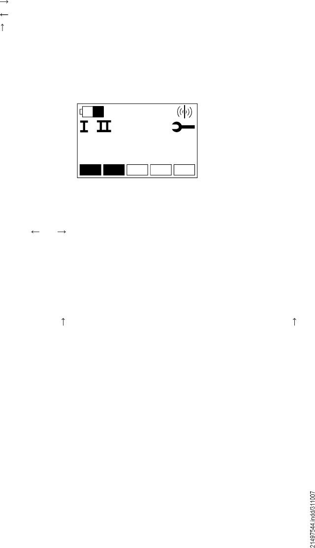
48
This parameter defines the time (in seconds) after which the joystick control sys-
tem switches from STOP mode into power-saving Standby mode (sleep function).
The default value set in the factory is a time period of 300 sec.
The current time period is shown in the display. To navigate, use the following
keys:
Key Function
Change to display of parameter 006
Change to display of parameter 004
Exit parameter programming menu
F1 Change to entry and selection mode
After changing to entry mode, the colon following the parameter code 005 is re-
placed by an equals symbol. Instead of the current value, the character string
!0&&" is displayed:
1.7 Displaying and
entering the cut-out
time in STOP mode,
Parameter code 005
1.7.1 Display mode
1.7.2 Entry and selection mode
Õëêì
ð ó ó ó ó
ððëã
õ
Entry starts with the first character on the left.
Use the and keys to select the character for the current position. Only figures
0 % 9 may be used.
Change to the next position by actuating the F1 key.
Following complete, correct entry, confirm the new value by actuating the F2 key.
Entry and the joystick control system parameter programming menu can be exited
by actuating the key at any time. The parameter will remain unchanged, if the
key is actuated before the entered value has been accepted with F2.
1.7.3 Selection of figures
1.7.4 Changing to the next position
1.7.5 Confirming the new value
1.7.6 Exiting the menu
42694844.eps
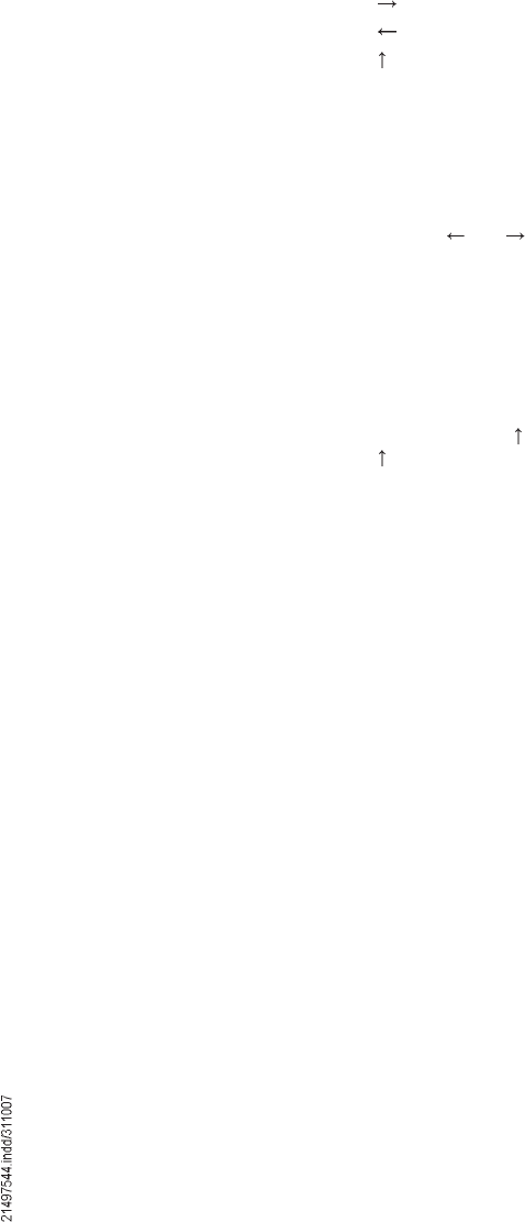
49
This parameter defines the time (in seconds) after which the joystick control sys-
tem switches from Operating mode into STOP mode (sleep function).
The default value set in the factory is a time period of 1800 sec.
The current time period is shown in the display. To navigate, use the following
keys:
Key Function
Change to display of parameter 007
Change to display of parameter 005
Exit parameter programming menu
F1 Change to entry and selection mode
After changing to entry mode, the colon following the parameter code 006 is re-
placed by an equals symbol. Instead of the current value, the character string
!0&&" is displayed. Entry starts with the first character on the left.
Use the and keys to select the character for the current position. Only figures
0 % 9 may be used.
Change to the next position by actuating the F1 key.
Following complete, correct entry, confirm the new value by actuating the F2 key.
Entry and the joystick control system parameter programming menu can be exited
by actuating the key at any time. The parameter will remain unchanged, if the
key is actuated before the entered value has been accepted with F2.
1.8 Display and entry of
the cut-out time in
Run mode, Parameter
code 006
1.8.1 Display mode
1.8.2 Entry and selection mode
1.8.3 Selection of figures
1.8.4 Changing to the next position
1.8.5 Confirming the new value
1.8.6 Exiting the menu
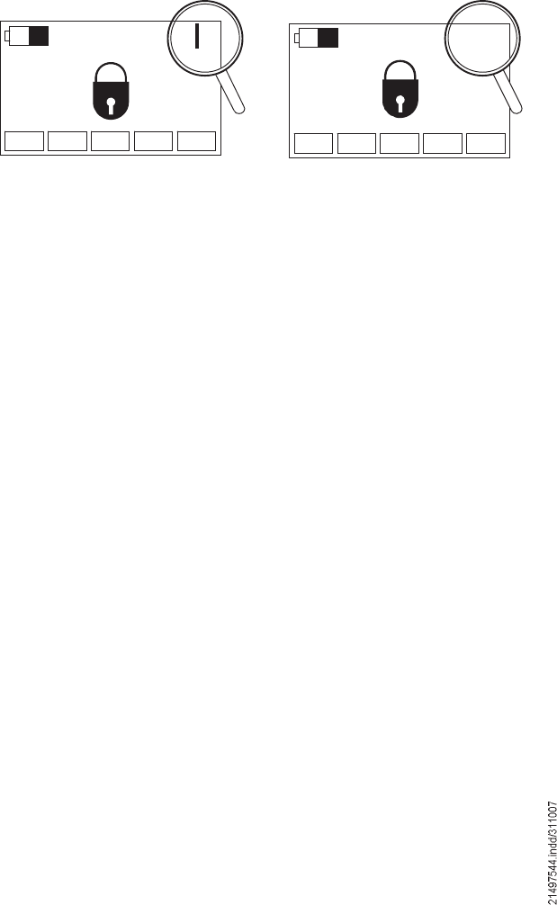
50
DRC-J joystick control systems operated with the frequency hopping method can
also be combined with older receivers not featuring the frequency hopping method.
In this case, set the DRC-J joystick control system to !Locked frequency opera-
tion", see chapter DRC-J joystick control system parameter programming, section
1.6: Displaying and entering a fixed frequency channel.
The display of the DRC-J joystick control system shows whether it is a frequency
hopping transmitter or not, see figure below.
1.9 Frequency hopping
1.9.1 Downward compatibility with
older receivers
Transmitter without frequency hopping Transmitter with frequency hopping
ÒÑ×Ü ááá
ÒÑ×Ü
42718244.eps42718344.eps

51
Notes

Reproduction in whole or in part only with prior consent of Demag Cranes & Components GmbH, D-58286 Wetter Subject to change. Not liable for errors or omissions.
Notices and Warnings
This device complies with part 15 of the FCC Rules and RSS-210 of IC Rules.
Operation is subject to the following two conditions: (1) This device may not
cause harmful interference, and (2) this device must accept any interference
received, including interference that may cause undesired operation. Changes or
modifications not expressly approved by Scanreco Industrielektronik AB will void
the user’s authority to operate the equipment.