Scanreco D2MPTR03FH917 Receiver User Manual DRC MP
Scanreco AB Receiver DRC MP
UserManual.wiki
>
Scanreco
>
D2MPTR03FH917 User Manual
Users Manual
Navigation menu
Upload a User Manual
Namespaces
Wiki Guide
HTML
PDF
Info
Views
User Manual
Discussion / Help
Navigation

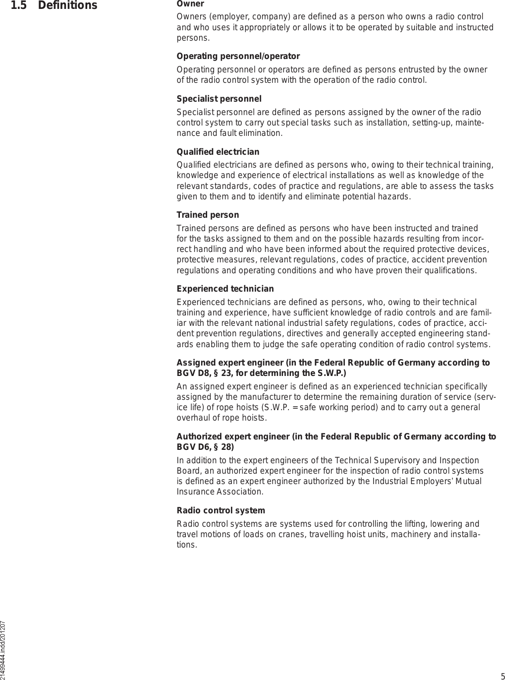
![19No.Switch 1Switch 2Switch 3Switch 4Switch 5Crane in [sec.]Trolley in [sec.]0OFFOFFOFFOFFOFF001OFFOFFOFFOFFON012OFFOFFOFFONOFF023OFFOFFOFFONON02,54OFFOFFONOFFOFF035OFFOFFONOFFON106OFFOFFONONOFF117OFFOFFONONON128OFFONOFFOFFOFF12,59OFFONOFFOFFON1310OFFONOFFONOFF2011OFFONOFFONON2112OFFONONOFFOFF2213OFFONONOFFON22,514OFFONONONOFF2315OFFONONONON2,5016ONOFFOFFOFFOFF2,5117ONOFFOFFOFFON2,5218ONOFFOFFONOFF2,52,519ONOFFOFFONON2,5320ONOFFONOFFOFF3021ONOFFONOFFON3122ONOFFONONOFF3223ONOFFONONON32,524ONONOFFOFFOFF33For example of setting no. 16, see tableFor example of setting no. 7, see table42690444.eps 42690544.epsExample DIP switch SW1Example DIP switch SW1Changes of the DIP switch settings only become effective when the receiver is switched on again.BE switch 1BE switch 2BE switch 3BE switch 4BE switch 5Encoded/un-encoded inputSGDM functionLower-fast relayBE switch 1BE switch 2BE switch 3BE switch 4BE switch 5Encoded/un-encoded inputSGDM functionLower-fast relay](https://usermanual.wiki/Scanreco/D2MPTR03FH917/User-Guide-1123356-Page-19.png)