User Manual
Instruction Manual
66064 AEnglish
Document Revision Language
G5 CU M
Attribute Information
Document Type Instruction Manual
Title SCANRECO G5 CU M
Document No. 66064
Language English
Release date 2013-05-20
Original English
Release date (original) 2013-05-20
Author SCANRECO
Company SCANRECO AB, SWEDEN
Revision Date Note
A 2013-05-20 First release
Document information
Revision history
All rights reserved
Design, equipment, technical data and specications are subject to change or improvement
without prior notice. The text in this instruction manual, or any part of it may not be reproduced
or transmitted in any form or by any means, including electronic, mechanical, photocopying,
recording, storage in an information retrieval system, or otherwise, without prior written permis-
sion of SCANRECO AB, SWEDEN.
Document type Document number PageRev
Instruction Manual 66064 A2 of 9
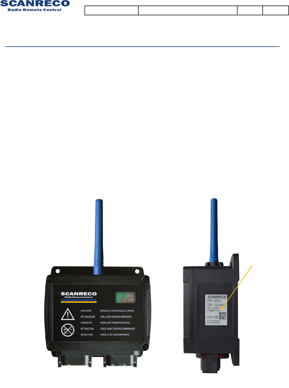
G5 receiver
Product description
The Central Unit (CU) is manufactured in robust plastic housing and provides contacts for
the connection of power supply and electro-hydraulic valves. Several of the outputs can
also be used as digital inputs. Depending on the version of the G5 Central unit, it can either
be equipped with MOSFET outputs and Deutsch connectors or can have relay outputs with
terminal block.
Since the central unit can be exposed to very tough environments, the box is encapsulated
to give protection from damp, heat, cold, dust, vibration and corrosive environments.
The Central unit has short circuit protected inputs and outputs and has protection against
reverse polarity, over-voltage, large incoming voltage transients and EMC/RF.
Label
Document type Document number PageRev
Instruction Manual 66064 A3 of 9

MOSFET Digital Output
The MOSFET digital outputs are designed to control electro-hydraulic valves but can also be used
to load other accessories such as lamps or motors.
Digital inputs
Estop
The digital inputs can be used as a switch to control different functions on the central
unit or on the HCU. The maximum input voltage shall not exceed the supply voltage.
The Estop function works as a safety function.
The output is active each time the HCU is active and communication has been established with
the Central unit. This output is normally connected to a dump valve. It is required for the system
installer to use this or similar function for the operator safety.
The Estop digital output shares the same properties as the other digital outputs.
Exspansion boards
Description of expansion functions Number of exspansion function
Analof inputs 1-10
Analog outputs 1-5
Digital I/O 1-20
PWM 1-5
The main board may be used stand alone or together with one expansion board.
There are several different expansion boards.
All expansions boards have the same mechanical outline.
They may have different funcionalities depending on customers application.
The differnt functions are exemplied in the table below:
Document type Document number PageRev
Instruction Manual 66064 A
4 of 9
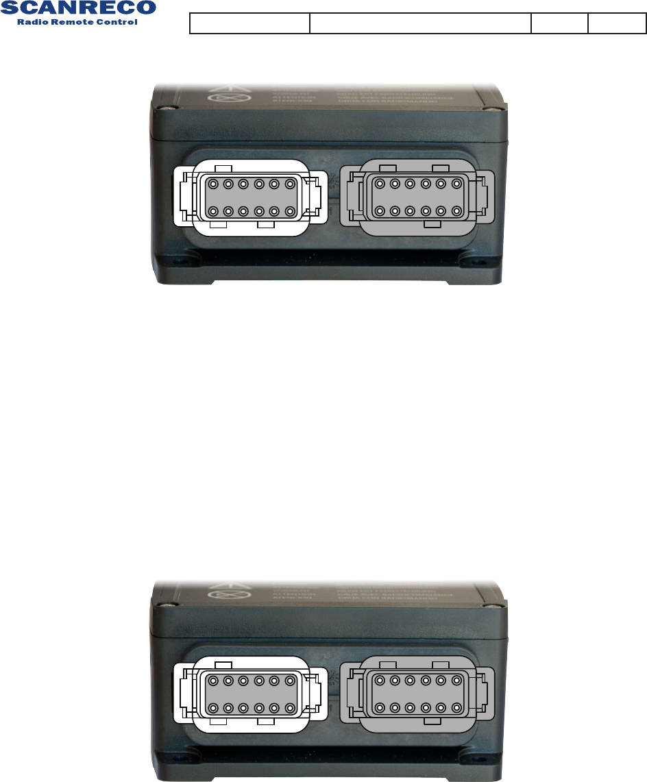
Main board
Main board with expansion board (49837)
Terminal schematics G5-CU M19
Terminal schematics G5-CU M21
1
12
2
11
3
10
4
9
5
8
6
7
7
6
8
5
9
4
10
3
11
2
12
1
1
12
2
11
3
10
4
9
5
8
6
7
7
6
8
5
9
4
10
3
11
2
12
1
1 = Output/input 16
2 = Output/input 15
3 = GND
4 = Output/input 14
5 = Estop
6 = Power Supply +
7 = Output 1
8 = Output 2
9 = Output 3
10 = Output 5
11 = Output 4
12 = Output/input 6
1 = Output/input 16
2 = Output/input 15
3 = GND
4 = Output/input 14
5 = Estop
6 = Power Supply +
7 = Output 1
8 = Output 2
9 = Output 3
10 = Output 5
11 = Output 4
12 = Output/input 6
1 = Output/input 7
2 = Output/input 8
3 = Output/input 9
4 = Output/input 10
5 = Output/input 11
6 = Output/input 12
7 = RS232 TX
8 = RS232 RX
9 = Output/input 13
10 = Output/input 17
11 = Output/input 18
12 = Output/input 19
1 = Output/input 7
2 = Output/input 8
3 = Output/input 9
4 = Output/input 10
5 = Output/input 11
6 = Output/input 12
7 = Mosfet output or 4 - 20 mA input
8 = Mosfet output or 4 - 20 mA input
9 = Output/input 13
10 = Output/input 17
11 = Output/input 18
12 = Output/input 19
Document type Document number PageRev
Instruction Manual 66064 A5 of 9
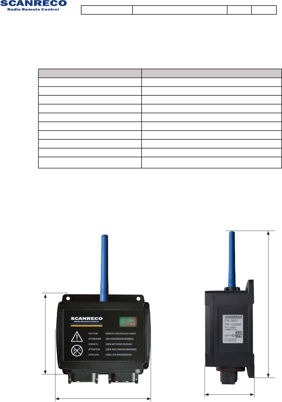
127mm 57mm
186mm
117mm
Size: approx. ~
127 x 117 x 57 mm / ~ 5,0 x 4,6 x 2,2 in.
Technical Data Central Unit
Attribute Information
Housing material Plastic PC
IP-class IP67 (for versions with cable glands IP65)
Ambient temperature -25˚C to +70˚C
Supply voltage 9-36VDC
Fuse Not required.
Current consumption at idle <30mA
MOSFET Output load 3 A, Max simultaneously load for each CU is 10A.
Relay Output load Max 10 A
Housing screw torque 0,8 Nm
Weight Approx. 0,5Kg
Document type Document number PageRev
Instruction Manual 66064 A
6 of 9
Attribute Information
Frequency 2,400 - 2,4835 GHz
Channels
management
FHSS
DSSS
THSS
Channel order Pseudorandom
Channel
capacity
Duplex
System
address/ID
<16777216 unique system addresses available
Redundancy CRC-16
Range 100 meters
Technical information
The G5 system family incorporates an automated frequency jumping technology, a reliable
radio transmission highly resistant to interference.
The radio transmission takes place within the ISM-band used at pre-dened channels.
The channel switching takes place multiple times per second following a pseudorandom se-
quence. This ensures that transmission takes place on an optimal frequency at all times!
No transmitter uses the same pseudorandom sequence order when switching channels; this
minimizes the risk of two G5 systems interfering with each other.
The G5 Pocket is approved to transmit on the ISM band.
The radio is license free for the end user.
Radio information
Document type Document number PageRev
Instruction Manual 66064 A7 of 9

This equipment has been tested and found to comply with the limits for a Class
A digital device, pursuant to part 15 of the FCC Rules. These limits are designed to
provide reasonable protection against harmful interference when the equipment
is operated in a commercial environment. This equipment generates,uses, and can
radiate radio frequency energy and, if not installed and used in accordance with the
instruction manual, may cause harmful interference to radio communications.
Operation of this equipment in a residential area is likely to cause harmful
interference in which case the user will be required to correct the interference at
his own expense.
This device complies with part 15 of the FCC Rules. Operation is subject to
the following two conditions: (1) This device may not cause harmful interference,
and (2) this device must accept any interference received, including interference
that may cause undesired operation.
This device complies with Industry Canada licence-exempt RSS standard(s).
Operation is subject to the following two conditions: (1) this device may not cause
interference, and (2) this device must accept any interference, including interference
that may cause undesired operation of the device.
Le présent appareil est conforme aux CNR d’Industrie Canada applicables aux
appareils radio exempts de licence. L’exploitation est autorisée aux deux conditions
suivantes : (1) l’appareil ne doit pas produire de brouillage, et (2) l’utilisateur de
l’appareil doit accepter tout brouillage radioélectrique subi, même si le brouillage
est susceptible d’en compromettre le fonctionnement.
CAN ICES-3 (A)/NMB-3(A)
The antenna(s) used for this transmitter must be installed to provide a separation
distance of at least 20 cm from all persons and must not be co-located or operating
in conjunction with any other antenna or transmitter.
L’antenne (s) utiliseé pour cet émetteur doit être installé pour fournir une distance
de séparation d’au moins 20 cm de toute personne et ne doit pas être co-localisées
ou opérant en conjonction avec une autre antenne ou émetteur.
Changes or modications not expressly approved by the party responsible for
compliance could void the user’s authority to operate the equipment.
Warning
FCC information
Industry Canada Information
Document type Document number PageRev
Instruction Manual 66064 A8 of 9

Changes or modications not expressly approved by the party responsible for
compliance could void the user’s authority to operate the equipment.