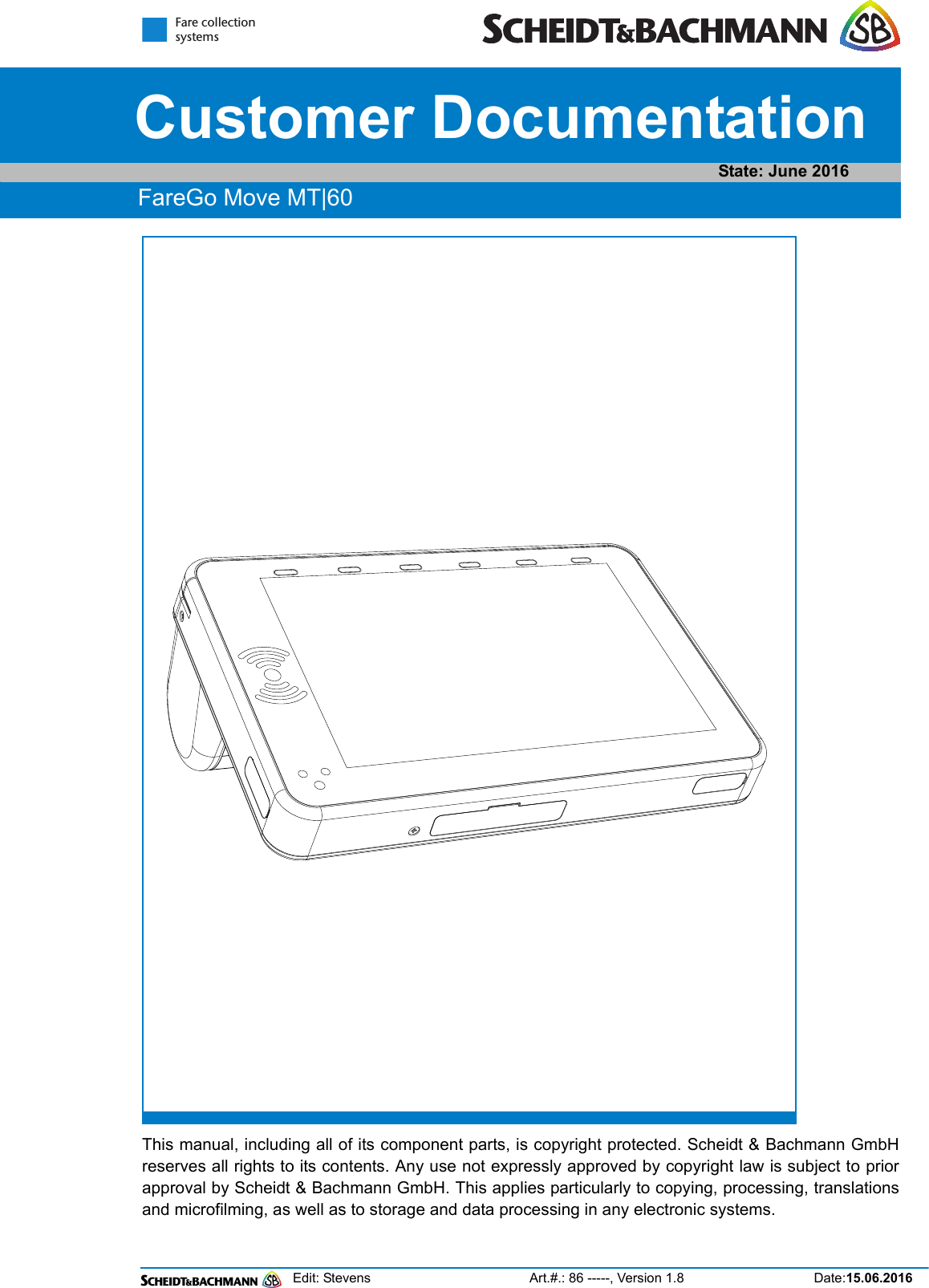
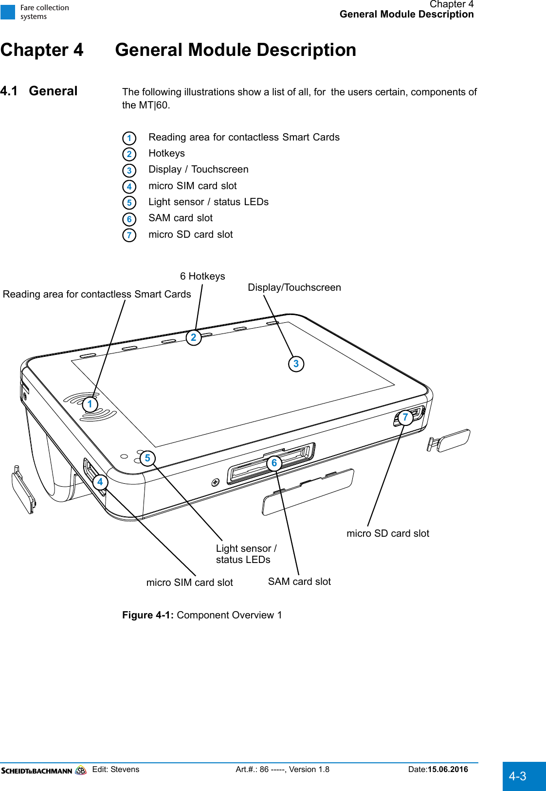
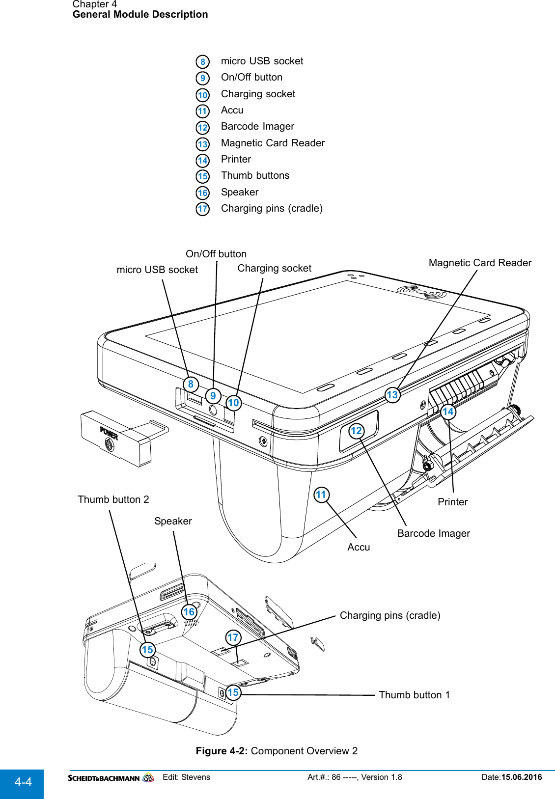
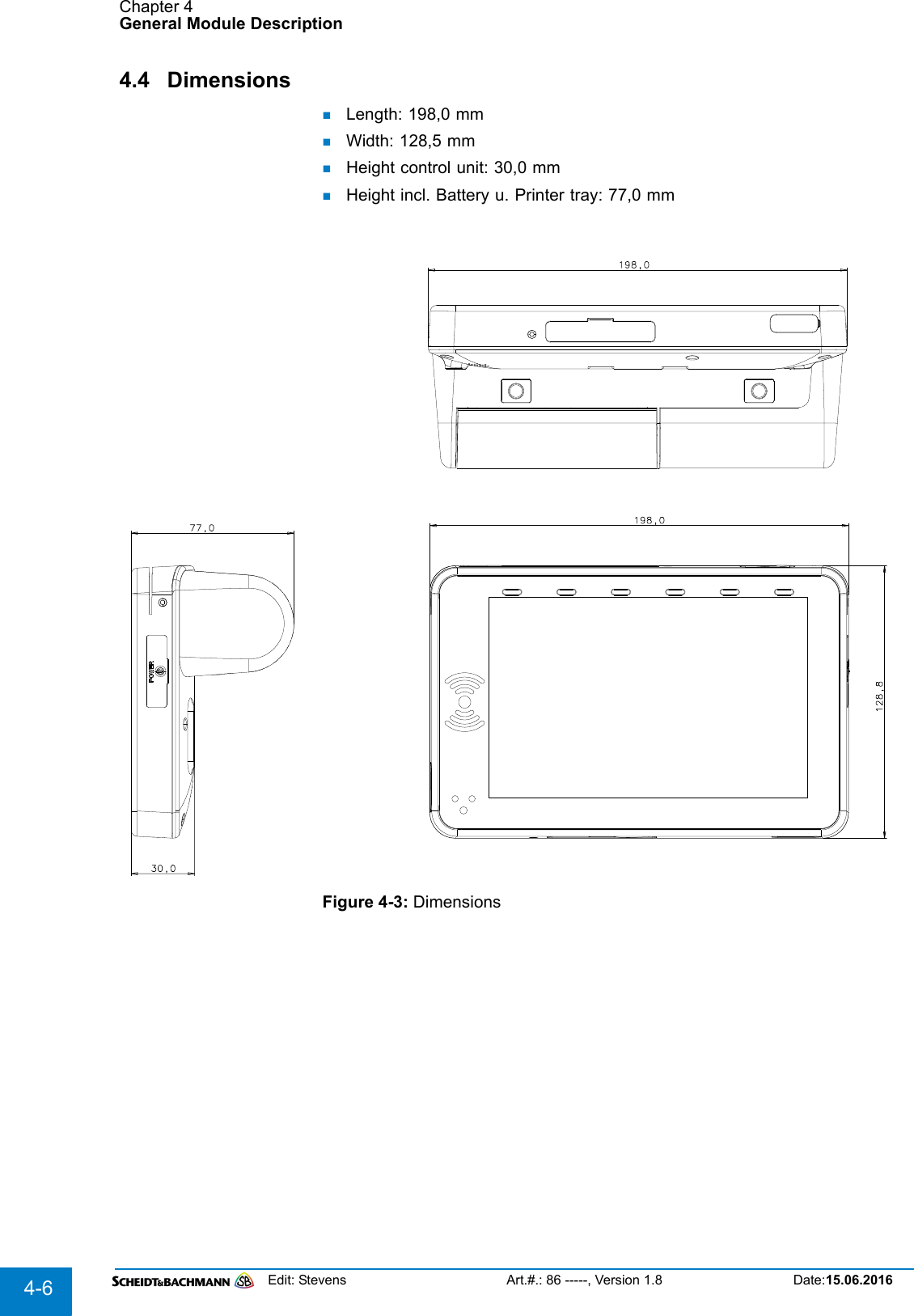
Scheidt and Bachmann MT60 Multi-functional ticketing inspection device User Manual FareGo Move MT 60

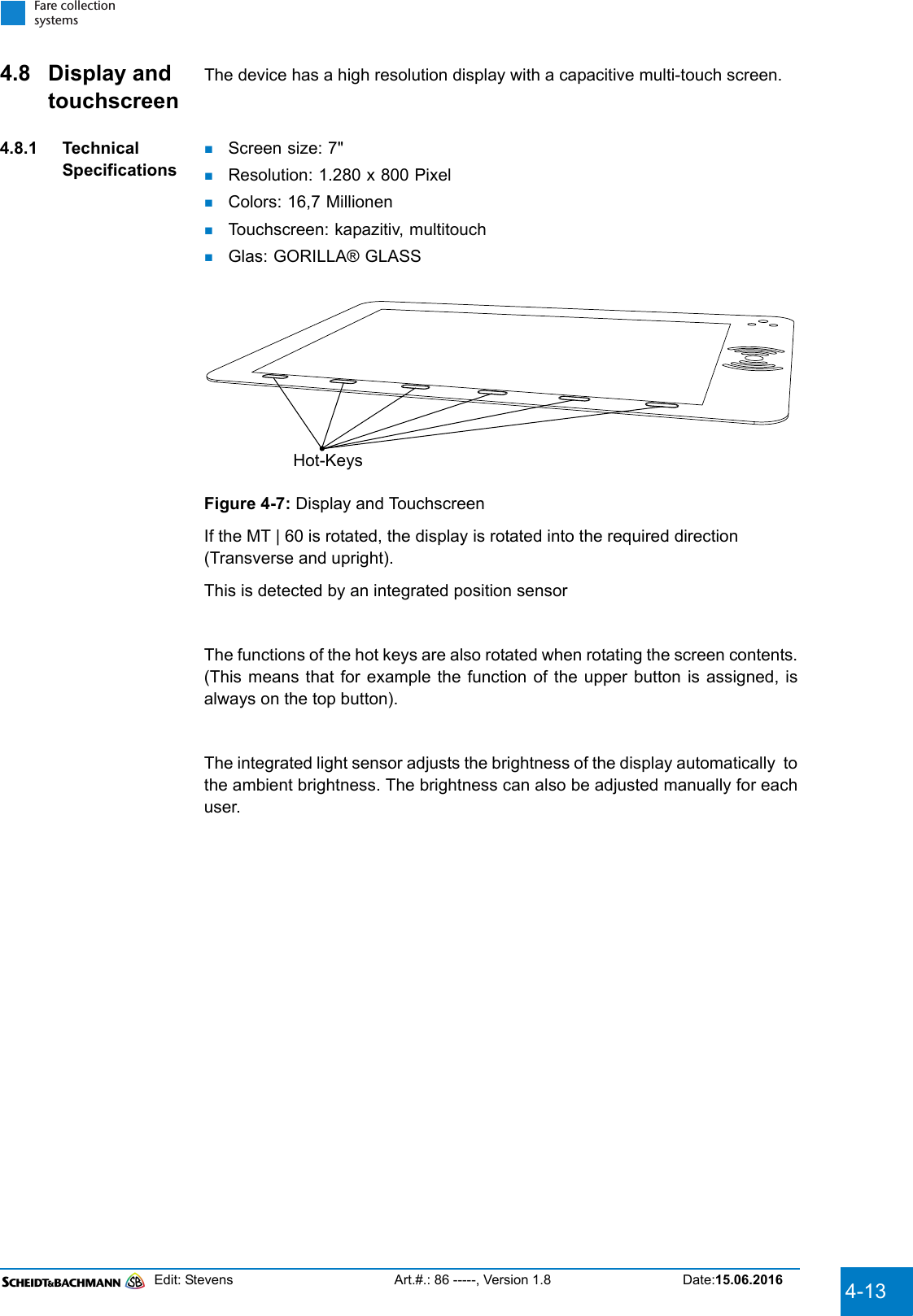
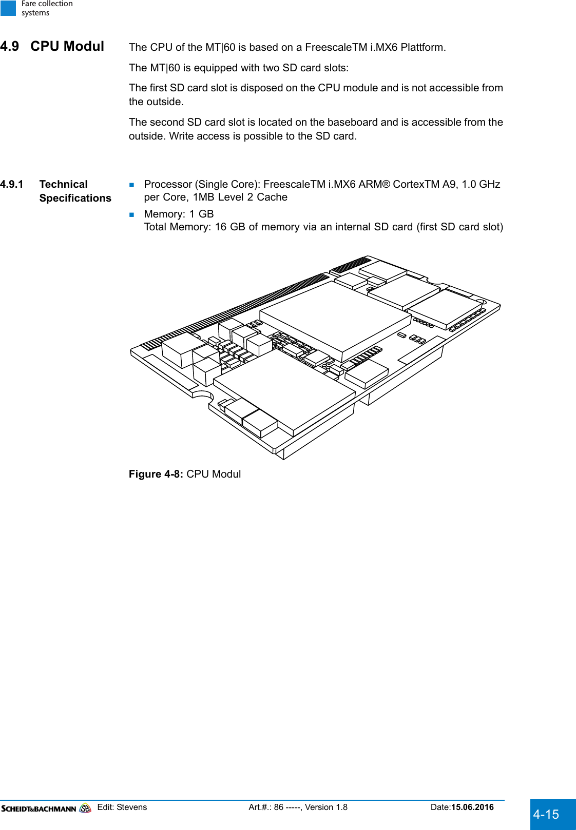
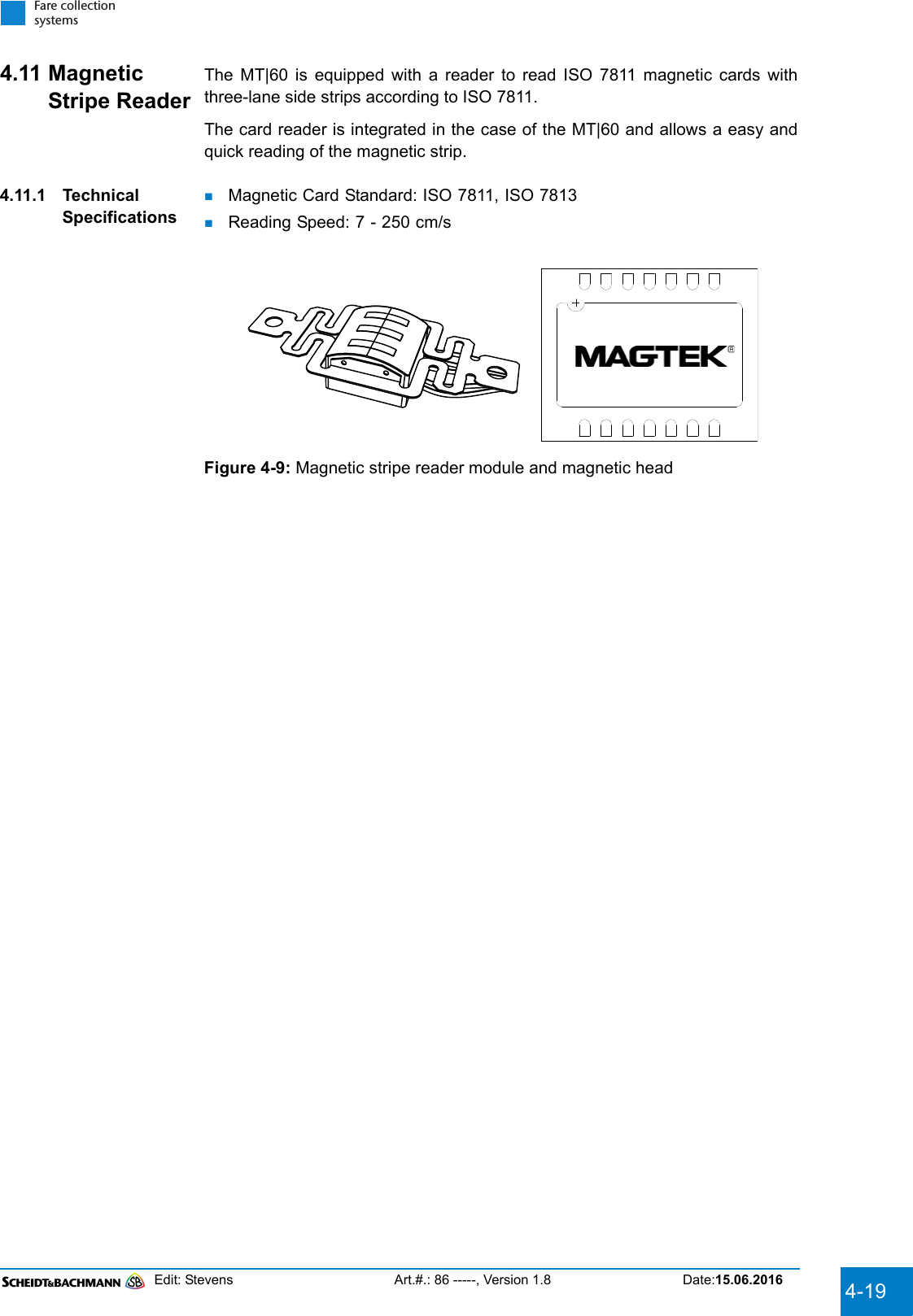
Scheidt & Bachmann GmbH Multi-functional ticketing inspection device FareGo Move MT 60

UserManual

Edit: Stevens Art.#.: 86 -----, Version 1.8 Date:15.06.2016Fare collectionsystems This manual, including all of its component parts, is copyright protected. Scheidt & Bachmann GmbHreserves all rights to its contents. Any use not expressly approved by copyright law is subject to priorapproval by Scheidt & Bachmann GmbH. This applies particularly to copying, processing, translationsand microfilming, as well as to storage and data processing in any electronic systems. State: June 2016Customer DocumentationFareGo Move MT|60
Edit: Stevens Art.#.: 86 -----, Version 1.8 Date:15.06.2016All contents of this manual shall be treated confidentially and shall not be transferred to any third party, eitherfor their own commercial use or for any other client.Since all information and facts are subject to technical changes, any liability for the data contained is herebydisclaimed. Modifications of technical details, in terms of information and illustrations are reserved. Makesure to follow the updating index. Scheidt & Bachmann GmbH cannot be held responsible for direct damageand/or possible consequential damage due to misuse by the customer or by third parties, unless the ProductLiability Act (ProdHaftG) is concerned. In no event shall Scheidt & Bachmann GmbH be liable for any dam-age out of or in connection with the provision of the manual.© 2016 Scheidt & Bachmann GmbH, Fare collection system (FCS) Breite Straße 132 41238 Mönchengladbach www.scheidt-bachmann.comSubject to change.HistoryVersion Date Change Edit0.8 18.09.2014 First draft Stevens1.0 24.09.2014 Formatting adapted to project specificationsStevens1.1 25.08.2015 Subject to alterations by project manager Stevens1.2 08.09.2015 Subject to alterations by project manager Stevens1.3 15.09.2015 Safety hint for outlet inserted Stevens1.4 03.12.2015 Power supply inforation changed Stevens1.5 03.06.2016 Safety hint for "distance between the radiator and body" insertedStevens1.6 08.06.2016 Chapter "Protective Cover" inserted Stevens1.7 09.06.2016 Chapter sequence corrected. Changes in Chapter 4.13Stevens1.8 15.06.2016 Chapter 2 corrected. StevensTable 1-1
Edit: Stevens Art.#.: 86 -----, Version 1.8 Date:15.06.2016 1-1Fare collectionsystemsChapter 1 Introduction1.1 Preliminary observations ......................................................................1-11.2 Explanation of symbols.........................................................................1-1Chapter 2 Declaration of ConformityChapter 3 Safety Features3.1 Generally.................................................................................................3-13.1.1 Training ..................................................................................................................... 3-13.1.2 Warranty.................................................................................................................... 3-13.2 Notes for Service....................................................................................3-13.2.1 Electrostatic discharge............................................................................................ 3-13.3 Maintenance ...........................................................................................3-23.3.1 Proof .......................................................................................................................... 3-23.3.2 Cleaning intervals..................................................................................................... 3-23.3.3 Detergent................................................................................................................... 3-23.3.4 Define maintenance cycles...................................................................................... 3-2
Edit: Stevens Art.#.: 86 -----, Version 1.8 Date:15.06.20161-2Chapter 4 General Module Description4.1 General....................................................................................................4-34.2 Standards ...............................................................................................4-54.3 Life cycle costs ......................................................................................4-54.4 Dimensions.............................................................................................4-64.5 Printer .....................................................................................................4-74.5.1 Technical Specifications ......................................................................................... 4-74.6 Barcode Imager......................................................................................4-94.6.1 Technical Specifications ......................................................................................... 4-94.7 Battery...................................................................................................4-114.7.1 Technical Specifications ....................................................................................... 4-114.7.2 Operating time ........................................................................................................ 4-114.7.3 Battery change ....................................................................................................... 4-114.7.4 Battery Label........................................................................................................... 4-124.8 Display and touchscreen ....................................................................4-134.8.1 Technical Specifications ....................................................................................... 4-134.9 CPU Modul............................................................................................4-154.9.1 Technical Specifications ....................................................................................... 4-154.10 NFC - Reader ........................................................................................4-174.10.1 Cards Standards..................................................................................................... 4-174.10.2 eTicketing Standards ............................................................................................. 4-174.11 Magnetic Stripe Reader .......................................................................4-194.11.1 Technical Specifications ....................................................................................... 4-194.12 Communication Modules ....................................................................4-214.12.1 Bluetooth.................................................................................................................4-214.12.2 WiFi.......................................................................................................................... 4-214.12.3 Mobile ...................................................................................................................... 4-214.12.4 USB.......................................................................................................................... 4-214.12.5 GPS (optional) ........................................................................................................ 4-214.13 Protective Cover ..................................................................................4-23
Edit: Stevens Art.#.: 86 -----, Version 1.8 Date:15.06.2016 1-3Fare collectionsystemsChapter 5 Commissioning5.1 Insert SIM, SAM, and micro SD Card....................................................5-15.2 Insert battery ..........................................................................................5-15.3 Recharge battery....................................................................................5-25.4 Insert Paper ............................................................................................5-35.5 Switch On/Off .........................................................................................5-65.6 First Start ................................................................................................5-6Chapter 6 Explanation of terms
Edit: Stevens Art.#.: 86 -----, Version 1.8 Date:15.06.20161-4   THIS PAGE INTENTIONALLY BLANK.
Chapter 1IntroductionEdit: Stevens Art.#.: 86 -----, Version 1.8 Date:15.06.2016 1-1Fare collectionsystemsChapter 1  Introduction1.1 Preliminary observationsThe aim of this manual is to provide knowledge on handling and work processesthat ensure that the device is working properly throughout its lifetime.All activities that are necessary to meet this requirement, were included in thismanual All activities can be performed by the staff, safely, easily, ergonomically and with-out tools.Organization of This Guide1. Chapter - Introduction2. Chapter - Declaration of Conformity3. Chapter - Safety Features4. Chapter - General Module Description5. Chapter - Commissioning6. Chapter - Explanation of terms1.2 Explanation of symbolsThis symbol indicates a WARNING. A detailed description of the particularhazard will appear next to the symbol in bold, italic print.This symbol indicates a CAUTION. A detailed description of the particularhazard will appear next to the symbol in bold, italic print.This symbol indicates that more INFORMATION follows. A detaileddescription of the particular hazard will appear next to the symbol in bold,italic print.This symbol indicates that lubrication is necessary. A detailed descriptionof the task will appear next to the symbol in bold, italic print.This symbol indicates possibility of ELECTRICAL HAZARD. A detaileddescription of the particular hazard will appear next to the symbol in bold,italic print.
Chapter 1IntroductionEdit: Stevens Art.#.: 86 -----, Version 1.8 Date:15.06.20161-2This symbol indicates an ESD HAZARD. A detailed description of theparticular hazard will appear next to the symbol in bold, italic print.This symbol indicates a RISK OF BURNS. A detailed description of theparticular hazard will appear next to the symbol in bold, italic print.
Chapter 2Declaration of ConformityEdit: Stevens Art.#.: 86 -----, Version 1.8 Date:15.06.2016 2-1Fare collectionsystemsChapter 2  Declaration of ConformityThis Declaration is valid as soon as CE,FCC and IC certifications are available.NOTICE:This device complies with Part 15 of the FCC Rules and with Industry Canada licence-exempt RSS standard(s).Operation is subject to the following two conditions:1. this device may not cause harmful interference, and 2. this device must accept any interference received, including interference thatmay cause undesired operation.Le présent appareil est conforme aux CNR d'Industrie Canada applicables aux appareils radioexempts de licence. L'exploitation est autorisée aux deux conditions suivantes:(1) l'appareil ne doit pas produire de brouillage, et (2) l'utilisateur de l'appareil doit accepter tout brouillage radioélectrique subi,même si le brouillage est susceptible d'en compromettre le fonctionnement.NOTICE:Changes or modifications made to this equipment not expressly approved by(manufacturer name) may void the FCC authorization to operate this equipment.Radiofrequency radiation exposure Information:This equipment complies with FCC radiation exposure limits set forth for anuncontrolled environment. To ensure the minimum operating distance betweenthe radiator and your body a protective cover is attached to the equipment. SeeChapter 4.13 for more details. This protective cover must not be removed if theequipment is used in the USA or Canada. This transmitter must not be co-located or operating in conjunction with any other antenna or transmitter.The radiated output power of the device is far below the FCC radio frequencyexposure limits. Nevertheless, the device shall be used in such a manner thatthe potential for human contact during normal operation is minimized.For body worn operation, this equipment has been tested and meets the FCCRF exposure guidelines when used with the Scheidt & Bachmann accessoriessupplied or designated for this product. Use of other accessories may not ensurecompliance with FCC RF exposure guidelines.
Chapter 2Declaration of ConformityEdit: Stevens Art.#.: 86 -----, Version 1.8 Date:15.06.20162-2NOTE: This equipment has been tested and found to comply with the limits fora Class B digital device, pursuant to Part 15 of the FCC Rules. These limits aredesigned to provide reasonable protection against harmful interference whenthe equipment is operated in a commercial environment. This equipment gener-ates, uses, and can radiate radio frequency energy and, if not installed and usedin accordance with the instruction manual, may cause harmful interference toradio communications. Operation of this equipment in a residential area is likelyto cause harmful interference in which case the user will be required to correctthe interference at his own expense.NOTE: This equipment has been tested and found to comply with the limits for a Class B digital device, pursuant to Part 15 of the FCC Rules.  These limits are designed to provide reasonable protection against harmful interference in a residential installation.  This equipment generates, uses and can radiate radio frequency energy and, if not installed and used in accordance with the instructions, may cause harmful interference to radio communications.  However, there is no guarantee that interference will not occur in a particular installation.  If this equipment does cause harmful interference to radio or television reception, which can be determined by turning the equipment off and on, the user is encouraged to try to correct the interference by one or more of the following measures:Reorient or relocate the receiving antenna.Increase the separation between the equipment and receiver.Connect the equipment into an outlet on a circuit different from that to which the receiver is connected.Consult the dealer or an experienced radio/TV technician for help.
Chapter 3Safety FeaturesEdit: Stevens Art.#.: 86 -----, Version 1.8 Date:15.06.2016 3-1Fare collectionsystemsChapter 3  Safety Features3.1 GenerallyAll operations such as installation, service, and maintenance must be performed only by trained and qualified personnel! Incorrectly performed installation, maintenance or repair actions may damage the unit.The manual is subject to constant revisions due to constantly new discoveries and newly emerging as experiences from long-term use. Check your documentation is always up to date.3.1.1 TrainingThe manual alone is not capable of performing the service. In addition to the documents a training at Scheidt & Bachmann is possible.To carry out maintenance and repair work on the device, the contained in this document has to be considered in the current version.3.1.2 Warranty The proper execution of all maintenance and repair work, particularly the obser-vance of maintenance intervals and the correct and proper implementation ofservice activities with the tools and practices described in these documents , isa prerequisite for the validity of the contractual warranty agreement.Instructions to service personnel that are generated from the maintenanceframework of your software application shall comply with the statements of thesedocuments, otherwise the contract warranty lose their validity.The power supply is designed exclusively for the power supply of the device.When used in other applications, the contract warranty will be invalid.The lower limit of the storage temperature of -20 ° C must not be exceeded.3.2 Notes for ServiceBefore opening the device, the accumulator and the power supply had to beremoved.3.2.1 Electrostatic dischargeThe components are used in the device, can be destroyed by electrostatic discharge. For this reason, generally wear a grounding ring during maintenance -and repair work and work in the workshop.During Service actions in the field, where direct or indirect contact with electrical components can accur, the use of a grounding ring is recommended.
Chapter 3Safety FeaturesEdit: Stevens Art.#.: 86 -----, Version 1.8 Date:15.06.20163-23.3 Maintenance3.3.1 Proof The Proof of maintenance cycle compliance and the regularity of the mainte-nance and repair work is up to the customer.3.3.2 Cleaning intervalsThe cleaning intervals had to be chosen so that, depending on the frequentation,no dangerous levels of paper dust and dirt can arise.3.3.3 Detergent By using detergent for plastic parts, the manufacturer information shall be fol-lowed so that these parts do not become brittle.3.3.4 Define maintenance cyclesScheidt & Bachmann reserves the right to change the guidelines of the mainte-nance cycles. Especially the printer. As a result of the knowledge from field
Chapter 4General Module DescriptionEdit: Stevens Art.#.: 86 -----, Version 1.8 Date:15.06.2016 4-3Fare collectionsystemsChapter 4  General Module Description4.1 General The following illustrations show a list of all, for  the users certain, components ofthe MT|60.Figure 4-1: Component Overview 1Reading area for contactless Smart CardsHotkeysDisplay / Touchscreenmicro SIM card slotLight sensor / status LEDsSAM card slotmicro SD card slot1723456Reading area for contactless Smart Cards6 HotkeysDisplay/Touchscreenmicro SD card slotSAM card slotLight sensor /micro SIM card slotstatus LEDs1234567
Chapter 4General Module DescriptionEdit: Stevens Art.#.: 86 -----, Version 1.8 Date:15.06.20164-4Figure 4-2: Component Overview 2micro USB socketOn/Off buttonCharging socketAccuBarcode ImagerMagnetic Card ReaderPrinterThumb buttonsSpeakerCharging pins (cradle)910111213141516178micro USB socketOn/Off buttonCharging socketPrinterAccuBarcode ImagerSpeakerCharging pins (cradle)Thumb button 1Thumb button 28910Magnetic Card Reader1311121415151617
Chapter 4General Module DescriptionEdit: Stevens Art.#.: 86 -----, Version 1.8 Date:15.06.2016 4-5Fare collectionsystems4.2 Standards The MT|60 conforms to the following standards:EN60950-1 Edition 2, IEC60950-1 - safetyEN60825-1, IEC60825-1 - Safety of laser products(The MT60 do not bear any laser. The barcode imager works with a LED aimer in compliance to class 1) IEC60529, IP54 - IK07 Protection of enclosuresRadio - R&TTE DirektiveEN 55022 Class B - electromagnetic compatibility (EMC)EN 55024 - noise immunity characteristicsApprovals cTÜV-Süd-us (NRTL) and FCC and IC- regulations conformities, approvalsCE, RoHS, WEEE - conformities and guidelinesETSI EN 300019-2-7 - vibration resistance4.3 Life cycle costsAll components of the MT | 60 are subject to aging. This wear automaticallypicks up after a few years. These components must be revised or replacedbefore the their life cycle end is reached, So before the aging process/wear ofthe components leads to major disruptions.Parts in this context are:BatteryDisplayPrinterPaper traySD-Card
Chapter 4General Module DescriptionEdit: Stevens Art.#.: 86 -----, Version 1.8 Date:15.06.20164-64.4 Dimensions Length: 198,0 mmWidth: 128,5 mmHeight control unit: 30,0 mmHeight incl. Battery u. Printer tray: 77,0 mmFigure 4-3: Dimensions
Edit: Stevens Art.#.: 86 -----, Version 1.8 Date:15.06.2016 4-7Fare collectionsystems4.5 Printer The MT|60 is equipped with a high performance thermal printer for printing tick-ets and receipts. The printer is integrated in the case of the MT|60.4.5.1 Technical SpecificationsResolution: 200 dpiPaper width: 82,5 mmPrint width: Effective printing width max. 72 mmMaximum allowed paper weight: 60 - 80 g/m²Paper feed: "Easyload" Paper-insertion mechanismPrint speed: 10 cm Ticket in max. 10 Seconds.Paper tear-off edge: Manual separation edge with corrosion-resistant metal edgePaper capacity: 10 mFigure 4-4: Printer
Edit: Stevens Art.#.: 86 -----, Version 1.8 Date:15.06.20164-8THIS PAGE INTENTIONALLY BLANK.
Edit: Stevens Art.#.: 86 -----, Version 1.8 Date:15.06.2016 4-9Fare collectionsystems4.6 Barcode ImagerFor the evaluation of barcodes (1D/2D) a barcode-imager is integated in theMT|60.4.6.1 Technical SpecificationsThe imager includes a CMOS camera for reading bar codes from a paper tem-plate or from a screen of a cell phone. The bar code reader supports 1D and 2D barcodes. Accordance with the follow-ing specification.1-D Barcodes: Code 1282-D Barcodes: AztecPDF417QR CodeData of the barcode reader:Reading range: 6-15 cm LED Eye Safety: Class 1 category (safest class)Figure 4-5: Barcode ImagerOptional: Camera with 5 mega pixels eCAM57 (S&B Art. # 51802760)
Edit: Stevens Art.#.: 86 -----, Version 1.8 Date:15.06.20164-10THIS PAGE INTENTIONALLY BLANK.
Edit: Stevens Art.#.: 86 -----, Version 1.8 Date:15.06.2016 4-11Fare collectionsystems4.7 Battery During mobile operation the device is powered by a powerful Li-Ion battery.4.7.1 Technical Specifications Voltage: 7,2 VCharging voltage: 8.4 VPower: 24.48 WhCapacity: 3400 mAhmax. Charging current: 1625 mAmax. Current drain: 4875 mACharging time: <5 hours to 10% - 90% of the charge capacityBattery replacement: Battery replacement without tools in operation(Hot swapping)Battery technology: lithium-ion battery (no memory effect)Discharge temperature: -20 ° C to + 60 ° C4.7.2 Operating time The device runtime is >8 hours at normal shift conditions. The operating timedepends on the software applications, wireless operation settings, power man-agement settings, the brightness of the LCD screen and the ambient conditions.Figure 4-6: Battery4.7.3 Battery change The device has an integrated energy storage (backup battery) that allows bat-tery replacement without shutting down the unit (hot swapping). With theremoval of the battery, the device goes into Sleep mode and reduced inter aliathe back light of the display to reduce the power consumption of the integratedenergy storage.The integrated energy storage is charged in operation mode by the battery. Thisallows a continuous operation of the device.The internal energy storage can backup the device for a period of about 5 min-utes to replace the battery.The outlet to recharge the MT-60 must be installed near the device andmust be easily accessible.
Edit: Stevens Art.#.: 86 -----, Version 1.8 Date:15.06.20164-124.7.4 Battery LabelThe MT 60 provided with a power supply "19V/max 3,3A". The output voltage  imply the feature of safety extra low voltage as a limited power source. During connection to the ac/dc source the batteries recharge. It need not more than 4 1/2h to recharge the battery to full condition.Caution: use this power supply provided by Scheidt & Bachmann only. Otherwise a damage or risk of fire may cause.The MT60 provided with a removable battery type FareGo Move MT60 Battery cpl. 86 34471 0.The Battery consisting of UL-recognized Li-cells  and a battery management system (BMS) are in compliance with UL2054. The safeties are tested and recognized by an UL-Investigation and reported to BBFS2/MH45433. Additional to the BMS an internal fuse ensure a "limited power source" output voltage.This battery comply to safety standards as follows: IEC60950-1, LPS, UL2054, IEC62133, UN38.3.Caution: Replace battery with type MT60 - 86 34471 0 only! Otherwise it may cause a Risk of Fire and Explosion. Do Not Open, Crush, Heat Above +55C or incinerate.Model No.Nominal Voltage, V dcCapacity, Ah/WhMaximum Charging Voltage, V dcMaximum Charging Current, AMaximum discharge Current, ADis-charge Cutoff Voltage, VdcCell Config xS/yP Cell Mfg.Cell Model Number2S1P NCR-18650BF7.2 3.35Ah / 24.12Wh 8.4 1.6 4.8 5.0 2S-1P PanasonicNCR-18650BF
Edit: Stevens Art.#.: 86 -----, Version 1.8 Date:15.06.2016 4-13Fare collectionsystems4.8 Display and touchscreenThe device has a high resolution display with a capacitive multi-touch screen.4.8.1 Technical SpecificationsScreen size: 7"Resolution: 1.280 x 800 PixelColors: 16,7 MillionenTouchscreen: kapazitiv, multitouchGlas: GORILLA® GLASSFigure 4-7: Display and TouchscreenIf the MT | 60 is rotated, the display is rotated into the required direction (Transverse and upright).This is detected by an integrated position sensorThe functions of the hot keys are also rotated when rotating the screen contents.(This means that for example the function of the upper button is assigned, isalways on the top button).The integrated light sensor adjusts the brightness of the display automatically  tothe ambient brightness. The brightness can also be adjusted manually for eachuser.Hot-Keys
Edit: Stevens Art.#.: 86 -----, Version 1.8 Date:15.06.20164-14THIS PAGE INTENTIONALLY BLANK.
Edit: Stevens Art.#.: 86 -----, Version 1.8 Date:15.06.2016 4-15Fare collectionsystems4.9 CPU Modul The CPU of the MT|60 is based on a FreescaleTM i.MX6 Plattform.The MT|60 is equipped with two SD card slots:The first SD card slot is disposed on the CPU module and is not accessible fromthe outside.The second SD card slot is located on the baseboard and is accessible from theoutside. Write access is possible to the SD card.4.9.1 Technical SpecificationsProcessor (Single Core): FreescaleTM i.MX6 ARM® CortexTM A9, 1.0 GHz per Core, 1MB Level 2 CacheMemory: 1 GBTotal Memory: 16 GB of memory via an internal SD card (first SD card slot)Figure 4-8: CPU Modul
Edit: Stevens Art.#.: 86 -----, Version 1.8 Date:15.06.20164-16THIS PAGE INTENTIONALLY BLANK.
Edit: Stevens Art.#.: 86 -----, Version 1.8 Date:15.06.2016 4-17Fare collectionsystems4.10 NFC - Reader For the processing of contactless media ISO 14443 A or B, the device has aSmart Card Terminal.The Smart Card Terminal was developed as a multi-application terminal andoffers a maximum of flexibility in the processing of contactless media. The intel-ligent reader supports the parallel use of different smart card standards. Thereader automatically recognizes the card standard when presenting the card.Additional Smart Card standards can be added through a software downloadand a corresponding SAM extension in most cases.The terminal has a total of 2 ISO 7816 SAM slots.Two of the slots are accessible from the outside. To access the additional twoSAM slots, the device must be opened.4.10.1 Cards StandardsMIFARE Classic 1K/4K, MIFARE Plus 2K/4K S/XMIFARE DESfire EVO/EV1MIFARE UltralightSmart MXInnovision jewelNFC Smart-Card Emulation (passiv)4.10.2 eTicketing StandardsVDV-KAcustom standardScheidt & Bachmann Smart Card Standard
Edit: Stevens Art.#.: 86 -----, Version 1.8 Date:15.06.20164-18THIS PAGE INTENTIONALLY BLANK.
Edit: Stevens Art.#.: 86 -----, Version 1.8 Date:15.06.2016 4-19Fare collectionsystems4.11 Magnetic Stripe ReaderThe MT|60 is equipped with a reader to read ISO 7811 magnetic cards withthree-lane side strips according to ISO 7811. The card reader is integrated in the case of the MT|60 and allows a easy andquick reading of the magnetic strip.4.11.1 Technical SpecificationsMagnetic Card Standard: ISO 7811, ISO 7813Reading Speed: 7 - 250 cm/sFigure 4-9: Magnetic stripe reader module and magnetic head
Edit: Stevens Art.#.: 86 -----, Version 1.8 Date:15.06.20164-20THIS PAGE INTENTIONALLY BLANK.
Edit: Stevens Art.#.: 86 -----, Version 1.8 Date:15.06.2016 4-21Fare collectionsystems4.12 Commu-nication ModulesThe MT|60 has the following communication modules:BluetoothWiFiMobileUSB4.12.1 Bluetooth The integrated Bluetooth v3.0 EDR interface includes: A2DP (Advanced AudioDistribution Profile), HSP (Headset Profile) and HDP (Health Device Profile) inaddition to the normal Bluetooth connectivity.4.12.2 WiFi The integrated WiFi interface interface complies with the standard IEEE802.11a/b/g/n.4.12.3 Mobile The MT|60 supports the following wireless data connectivity standards:GPRSEDGEUMTSHSDPA oder HSPA+The device has an externally accessible slot for a micro-SIM card.4.12.4 USB The device is equipped with a micro USB 2.0 interfaceUSB OTG (USB On-The-Go).4.12.5 GPS (optional) The MT|60 can optionally be equipped with GPS.
Edit: Stevens Art.#.: 86 -----, Version 1.8 Date:15.06.20164-22THIS PAGE INTENTIONALLY BLANK.
Edit: Stevens Art.#.: 86 -----, Version 1.8 Date:15.06.2016 4-23Fare collectionsystems4.13 Protective CoverThe protective cover improves the drop resistance of the MT-60.The cover is an integral part of the MT-60 and can not be removed without tools.In some countries it is not allowed to operate the MT-60 without the protective cover to comply with the FCC guidelines.The device remains fully usable with the protective cover on.Figure 4-10: Protective Cover
Edit: Stevens Art.#.: 86 -----, Version 1.8 Date:15.06.20164-24THIS PAGE INTENTIONALLY BLANK.
Chapter 5CommissioningEdit: Stevens Art.#.: 86 -----, Version 1.8 Date:15.06.2016 5-1Fare collectionsystemsChapter 5  CommissioningFor the first commissioning, the following steps are necessaryInserting a micro SIM card (see Chapter 5.1)Inserting the SAM card/s for the Smart Card Reader (see Chapter 5.1)Insert a microSD card (see Chapter 5.1)Inserting the battery (see Chapter 5.2)Charging the battery (see Chapter 5.3)Inserting a paper roll (see Chapter 5.4)5.1 Insert SIM, SAM, and micro SD CardTo insert a micro SIM, -SAM - or a micro SD card, proceed as follows:Open the rubber covers of the to be equipped card slot.Place the desired card into the appropriate card slot. (see Fig. 5-1)All card slots have a spring mechanism that audible and tactile snaps into place when the inserted card is properly positionedTo remove a card, push the card a little further into the card slot until an audible and tactile trigger of the spring mechanism to be heard. When you release the card now, it is automatically pushed out by the spring mechanism.This makes it possible to easily remove the card now.Close the rubber covers of all card slots.Figure 5-1: Insert SIM, SAM and micro SD card5.2 Insert battery To replace the battery, proceed as follows:.Insert the battery to the guiding rails and slide it over the guiding rails as far until the battery snaps into placeSAM 1micro SIM-CardSAM 2microSD Card
Chapter 5CommissioningEdit: Stevens Art.#.: 86 -----, Version 1.8 Date:15.06.20165-2Figure 5-2: Installing the Battery step 1Figure 5-3: Installing the Battery step 25.3 Recharge batteryThe battery can be charged in two ways. At one via the contacts on the bottomof the unit. For this purpose, the device is placed on a charging station (cradle).To charge the battery via the charging socket, proceed as follows.Open the rubber covers, under which the charging soccer is located. (see Fig. 5-4)Plug the power supply cord into the charging socket.Please use exclusively the charging options provided by Scheidt & Bachmann  (power supply and Cradle).If using, power supplies do not meet the specifications, the unit may be damaged.When the battery is fully charged, disconnect the charger cable and close the rubber cover.The unit can not be loaded via the micro USB connector.The micro USB connector is used exclusively for data exchange.guiding railsguiding railsKLICK
Chapter 5CommissioningEdit: Stevens Art.#.: 86 -----, Version 1.8 Date:15.06.2016 5-3Fare collectionsystemsFigure 5-4: micro USB, On/Off Button, Charging socket, Charging contacts5.4 Insert Paper To load the paper, proceed as follows.Press from below against the paper tray cover until the upper part of the paper tray cover bounces off by a few millimeters to the front. The paper tray is now unlocked.Figure 5-5: Loading Paper Step 1micro USB socketOn/Off ButtonCharging socketCharging contacts
Chapter 5CommissioningEdit: Stevens Art.#.: 86 -----, Version 1.8 Date:15.06.20165-4Next step is to drag the paper cover on the top edge to the rear.Now the paper tray cover can be folded down.Figure 5-6: Loading Paper Step 2Insert the correct paper roll into the designated indentation in the paper tray cover.Roll the paper from the roll as far that the paper protrudes a few centimeters out of the printer after loading the paperFigure 5-7: Loading Paper Step 3
Chapter 5CommissioningEdit: Stevens Art.#.: 86 -----, Version 1.8 Date:15.06.2016 5-5Fare collectionsystemsFigure 5-8: Loading Paper Step 4The thermo sensitive side of the paper faces toward the printerClose the paper tray cover by pressing below against the cover until the top of the paper tray cover snaps into place.Figure 5-9: Loading Paper Step 5To lock the paper tray cover, press against the upper edge of the paper tray cover until it is completely latched and locked.Thermal coating
Chapter 5CommissioningEdit: Stevens Art.#.: 86 -----, Version 1.8 Date:15.06.20165-6Figure 5-10: Loading Paper Step 65.5 SwitchOn/OffTurning on and off of the MT|60 is done via the centrally disposed on/off switch.To turn on the MT|60, press the switch for 2-3 seconds.To turn off the MT|60 press the on/off switch for a longer time.However, the switching process needs to be confirmed by an additional displaydialog.Figure 5-11: On/Off switch5.6 First StartIn the delivery state or after resetting to factory settings, the MT|60 is equippedwith the standard components of the Android operating system and a demoapplication to test the operation of the Barcode Imager, the smart card reader,the magnetic stripe reader and the printer. For correct operation, the followingsettings should be checked and adjusted on first use:Regional SettingsTime and Time Zone
Chapter 6Explanation of termsEdit: Stevens Art.#.: 86 -----, Version 1.8 Date:15.06.2016 6-1Fare collectionsystemsChapter 6  Explanation of termsIn the context with manuals from Scheidt & Bachmann many terms and abbrevi-ations are used. Some terms are defined in industry standard, others are spe-cific to the application (e.g. Networking and telecommunications terms, etc..),others are specifically defined by Scheidt & Bachmann.All listed items are exclusively associated with products of Scheidt & Bachmann. Not all terms are valid for the product that is described in this manual. AA Ampere BBluetooth Radio-based data transmission standard CCECommunauté Européenne - With the CE marking, the manufacturer declares distributor or EU representative in accordance with EU Regulation 765/2008, "that the product meets the applicable requirements set out in the "Community harmonization legislation providing" providing for its affixingCPU Central Processing Unit D DC Direct Current E EDGE Enhanced Data Rates for mobile networksEMCEMC electromagnetic compatibilityThe EMC refers to a usually desirable state that technical devices do not interfere with each other disruptive due to unwanted electrical or electromagnetic effects.ENThe European Standards (EN) are rules that have been ratified by one of the three European Committee for Standardization.Error Code Also referred to as an error message. Error information is available on the Customer Display, Service Terminal Display, or printed report concerning a TVM fault or malfunction. ESD The Electrostatic Discharge symbol indicates the potential for serious damage to the printed circuit boards or other Electrostatic Discharge (ESD) sensitive devices in the machine.
Chapter 6Explanation of termsEdit: Stevens Art.#.: 86 -----, Version 1.8 Date:15.06.20166-2Ethernet Card The Ethernet Card is installed in the main computer. It provides a communications interface between the TVM and an ethernet Local Area Network (LAN). F FCCFederal Communications Commission - The FCC is (amateur radio, etc.) as well as responsible regulatory authority for communications devices such as radios, televisions and computers for various wireless services. It checks the devices for compatibility with the own and other standards.Flash Card The flash card is a storage module (PCMCIA) that is used for TVM initialization and data storage.  GGorilla GlassGorilla Glass is a protected wordmark for a thin chemically toughened glass from the group of the US manufacturer Corning of aluminosilicate glassesGPS Global Positioning System - radio-based data transmission standardGPRS General Packet Radio Service HHSDPA High Speed Downlink Packet Access Hotkey  Quick selection button that can be individually assigned with a function. I IC Industry Canada - Telecommunications Appliances accreditation standardIPInternational Protectioncodes - The IP protection specify the degree of protection of the housing against contact, foreign bodies and water.ID Identification NumberIEC International Electro-technical Commission K L LCD Liquid Crystal Display; see LCD Display. LED Light Emitting DiodeLCD Display Part of the Customer Display on the TVM. Light SensorA light sensor is a electronic component that converting light, using the photoelectric effect, in an electrical signal or shows a electrical resistance depending of the incident radiation M
Chapter 6Explanation of termsEdit: Stevens Art.#.: 86 -----, Version 1.8 Date:15.06.2016 6-3Fare collectionsystemsMT|60 Mobil Terminal 60 = Characteristics of the deviceMobile Radio-based data transmission standard N NFC Near Field Communication - Radio-based data transmission standard PPIN Personal Identification Number R RoHSRestriction of Hazardous Substances - Restriction of the use of certain hazardous substances in electrical and electronic equipmentR&TTE Guidelines for radio equipment and Telecommunication Terminal Equipment S SIM-KarteSubscriber Identity Module - The SIM card is a card that is plugged into a mobile phone and is used to identify the user within the networkSAM Secure Access ModuleSD Karte Secure Digital Memory Card - Data Storage DeviceS & B  Scheidt & Bachmann T Touch Screen  The Touch Screen is part of the Customer Display. It select inputs by pressing on the screen. U ULUnderwriters Laboratories - An organization tests products, components, materials and systems, whether they meet specific requirements. If this is the case, these products may show the chargeable UL Mark, as long as they meet the prescribed standardsUMTS Universal Mobile Telecommunications SystemUSB Universal Serial Bus - Contact-based communication standard V  W WEEEWaste of Electrical and Electronic Equipment - The WEEE Directive, the EU Directive 2002/96 / EC to reduce the increasing amount of electronic waste from disused electrical and electronic equipmentWLAN Wireless Local Area Network - Radio-based data transmission standard
Chapter 6Explanation of termsEdit: Stevens Art.#.: 86 -----, Version 1.8 Date:15.06.20166-4THIS PAGE INTENTIONALLY BLANK.

Navigation menu