Scheidt and Bachmann SCR SMART CARD READER User Manual Rechner Spezifikation
Scheidt & Bachmann GmbH SMART CARD READER Rechner Spezifikation
Contents
- 1. Users Manual
- 2. Installation Instructions
Installation Instructions
Installation Instructions
SCR-Smart Card Reader
The content of this document is protected by copyrights.
Date
Name
Created
28..11.11
Hen
File name:
B
--.--.--
-
-
-
Approved
28.11.11
Hen
03 65044 0 B.doc
Index
Date
Created
Approved
Standardization
Standardization
30.11.11
Jor
Scheidt & Bachmann GmbH
D-41238 Mönchengladbach Breite Straße 132
Installation
Instructions SCR
03 65044 0 __
Page: 1 of 8
1 Introduction
The Scheidt & Bachmann (S&B) 13,56 MHz RFID Smart Card Reader System “SCR” is
designed for exclusive application with S&B devices only. It will never be sold as single
system. S&B devices are products like ticket vending machines, pay on foot machines,
ticket dispensers, ticket validators etc. with
13,56 MHz RFID functionality.
SCR is integrated by a set of one common sandwich circuit board and one or two (see cp. 4)
of 2 different antenna types.
For operational description, pls. see cp. 2.
For block diagram, pls. see cp. 3.
For detailed antenna adaptation and pin assignment, pls. see cp. 4.
For detailed pin assignment, pls. see cp. 5.
For FCC/ IC information, pls. see cp. 6.

Installation Instructions
SCR-Smart Card Reader
The content of this document is protected by copyrights.
Date
Name
Created
28..11.11
Hen
File name:
B
--.--.--
-
-
-
Approved
28.11.11
Hen
03 65044 0 B.doc
Index
Date
Created
Approved
Standardization
Standardization
30.11.11
Jor
Scheidt & Bachmann GmbH
D-41238 Mönchengladbach Breite Straße 132
Installation
Instructions SCR
03 65044 0 __
Page: 2 of 8
2 Operational description
2.1 Basic operation principle
SCR is a 13,56Mhz RFID Transponder Read/ Write Unit for use in S&B equipment. It can be
used for various applications in S&B eqt, such as SmartCards, eTicketing, wireless creditcard
processing (EMV), etc. All such devices are under responsibility of S&B.
Corresponding partners for SCR are passive RFID Transponders, based on the ISO 14443 Type
A and B or Mifare standard. The transponders are passive units; the power supply of
transponders is realized via RF link of the SCR module.
SCR serves as an interface between data medium (transponder) and the S&B subsystem:
RF modulation and demodulation
Digital Data generation and detection
Intermediate memory (for processing and commands)
I/F to S&B eqt. (such as Ticket vending machines)
2.2 System Structure
The processor-based SCR solution consists of two PCBs (CPU module and baseboard):
The CPU module contains the CPU together with an FPGA. All necessary interface lines are fed
to two connectors. The CPU Module is plugged into the baseboard.
On the baseboard resides the power supply that converts the input voltage of 8V—12V into 5V
and 3.3V. Alternatively the SCR can be supplied with a 5V power supply. Additionally two
chips are implemented to interface to two independent antennas for transactions with contact less
smartcards. Another chip is used, to interface to four SAM (secure access module) sockets.
Finally there are all connectors, transceivers and other components integrated, that the SCR
needs to communicate to a host (USB 1.1, RS232) and to the customer (antenna, LEDs, buzzer).
The Smart Card Target (that is the area, where the customer shall tag the contact less smart
card) is a separate PCB, designed as antenna, with LED and a buzzer as user interface. The SCR
supports two independent antennas.
Four SAMs (secure access module) sockets are implemented to handle keys and to store
transaction data (depends on application).
The SCR is equipped with a USB compliant interface to perform upload of transactional and
event data and download of firmware versions and operational data.
The SCR can be equipped with a RS232 interface to perform the same data exchange that is
possible with USB.
Installation Instructions
SCR-Smart Card Reader
The content of this document is protected by copyrights.
Date
Name
Created
28..11.11
Hen
File name:
B
--.--.--
-
-
-
Approved
28.11.11
Hen
03 65044 0 B.doc
Index
Date
Created
Approved
Standardization
Standardization
30.11.11
Jor
Scheidt & Bachmann GmbH
D-41238 Mönchengladbach Breite Straße 132
Installation
Instructions SCR
03 65044 0 __
Page: 3 of 8
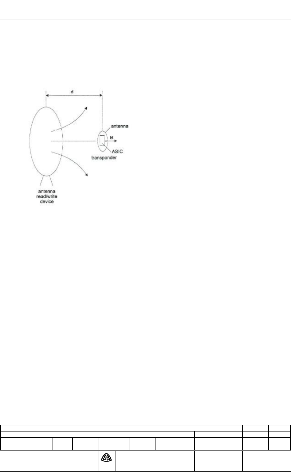
2.3 RF coupling of SCR and Transponder
Since electromagnetic coupling is used for data transmission between SCR and transponder and
power supply of the transponder the electromagnetic field is the most important attribute. The
following figure shows the run of the electromagnetic field lines with the transponder placed in
the antenna field.
The RF coupling is according to all layers of ISO 14443 Type A and B are supported.
Installation Instructions
SCR-Smart Card Reader
The content of this document is protected by copyrights.
Date
Name
Created
28..11.11
Hen
File name:
B
--.--.--
-
-
-
Approved
28.11.11
Hen
03 65044 0 B.doc
Index
Date
Created
Approved
Standardization
Standardization
30.11.11
Jor
Scheidt & Bachmann GmbH
D-41238 Mönchengladbach Breite Straße 132
Installation
Instructions SCR
03 65044 0 __
Page: 4 of 8
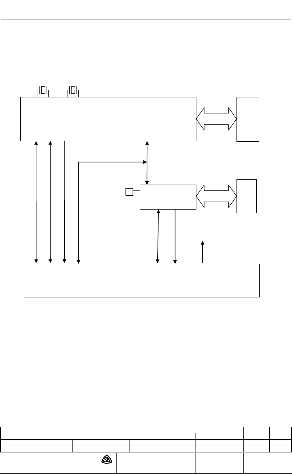
3 Block diagram: Circuit Board Transponder II 03 62101 0
CPU Module 03 53742 0
I2C
RS232
USB1.1
DATA / CONTROL
CONTROL
LED/BUZZER
FPGA
Memory
ARM 9 CPU
Memory
8 Bit Bus
connector to baseboard
+3.3V
18,432MHz
32,768 KHz
50 MHz
20MHz
Installation Instructions
SCR-Smart Card Reader
The content of this document is protected by copyrights.
Date
Name
Created
28..11.11
Hen
File name:
B
--.--.--
-
-
-
Approved
28.11.11
Hen
03 65044 0 B.doc
Index
Date
Created
Approved
Standardization
Standardization
30.11.11
Jor
Scheidt & Bachmann GmbH
D-41238 Mönchengladbach Breite Straße 132
Installation
Instructions SCR
03 65044 0 __
Page: 5 of 8
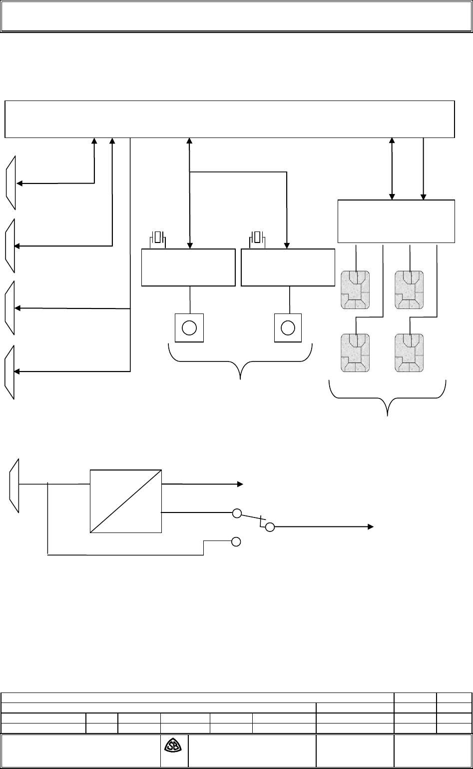
Baseboard 03 51634 0
DATA / CONTROL
IIC
USB 1.1
LED / BUZZER
LED / BUZZER
RS232
connector from CPU Modul
AT83C26
SAM sockets
50 Ohm Antenna
ISO 14443 Type A / B
8V..12V
3.3V
5V int.
VV
DC
DC
5V exten
MFRC 531
5V
V
V
MFRC 531
13,56 MHz
13,56 MHz
20MHz

Installation Instructions
SCR-Smart Card Reader
The content of this document is protected by copyrights.
Date
Name
Created
28..11.11
Hen
File name:
B
--.--.--
-
-
-
Approved
28.11.11
Hen
03 65044 0 B.doc
Index
Date
Created
Approved
Standardization
Standardization
30.11.11
Jor
Scheidt & Bachmann GmbH
D-41238 Mönchengladbach Breite Straße 132
Installation
Instructions SCR
03 65044 0 __
Page: 6 of 8
4 Antenna Setup
For SCR system, the following antenna setups can be used
Antenna Connector BU500 Antenna Connector BU550
03 57570 none
03 64127 none
none 03 57570
none 03 64127
03 57570 03 57570
03 57570 03 64127
03 64127 03 57570
Installation Instructions
SCR-Smart Card Reader
The content of this document is protected by copyrights.
Date
Name
Created
28..11.11
Hen
File name:
B
--.--.--
-
-
-
Approved
28.11.11
Hen
03 65044 0 B.doc
Index
Date
Created
Approved
Standardization
Standardization
30.11.11
Jor
Scheidt & Bachmann GmbH
D-41238 Mönchengladbach Breite Straße 132
Installation
Instructions SCR
03 65044 0 __
Page: 7 of 8
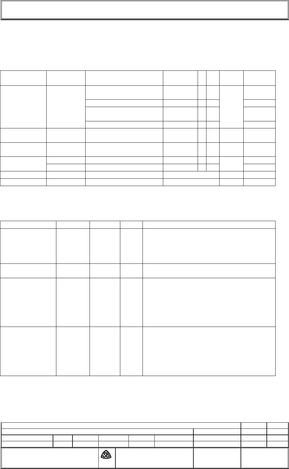
5 List of Cables and components
Cable
Functon
Connector
SCR
Type
No
Count
Length
Power 5V
5V
8V-24V
8V-24V
ST950
2 x AWG20 UL SW
50 62106
0
1
0-3m
3 x AWG20 C UL SW
50 60120
0
A
0-3m
2 x AWG20 UL SW
50 62106
0
0-3m
3 x AWG20 C UL SW
50 60120
0
A
0-3m
LED/Buzzer
ST572 /
ST582
6 x AWG24 C UL SW
50 61441
0
A
2
0-7,3m
Antenna
BU500 /
BU550
M17 / 113-RG316
5063381
0
2
0-7,3m
Host RS232
USB
ST301
4 x AWG24C UL CSA SW
50 61440
0
A
1
0-3m
BU410
0-5
Used components
Component
PCB
Version
Index
Remarks
Reader
Baseboard
03 51634
0
I
The Index shows current design state. Earlier
versions have been part of earlier FCC/IC
certification. Further indices will be covered by
this certification, as long as radio
characteristics will not be affected.
Reader
CPU Module
03 53742
0
I
./.
Antenna Type A
03 57570
./.
./.
To achieve the best performance the
adaptation of the antenna must be changed,
depending on the housing situation (resonance
adaptation).
Scheidt & Bachmann ensures, that resonance
parameters will be met under housing
conditions.
Antenna Type B
03 64127
./.
./.
To achieve the best performance the
adaptation of the antenna must be changed,
depending on the housing situation (resonance
adaptation).
Scheidt & Bachmann ensures, that resonance
parameters will be met under housing
conditions.
Installation Instructions
SCR-Smart Card Reader
The content of this document is protected by copyrights.
Date
Name
Created
28..11.11
Hen
File name:
B
--.--.--
-
-
-
Approved
28.11.11
Hen
03 65044 0 B.doc
Index
Date
Created
Approved
Standardization
Standardization
30.11.11
Jor
Scheidt & Bachmann GmbH
D-41238 Mönchengladbach Breite Straße 132
Installation
Instructions SCR
03 65044 0 __
Page: 8 of 8
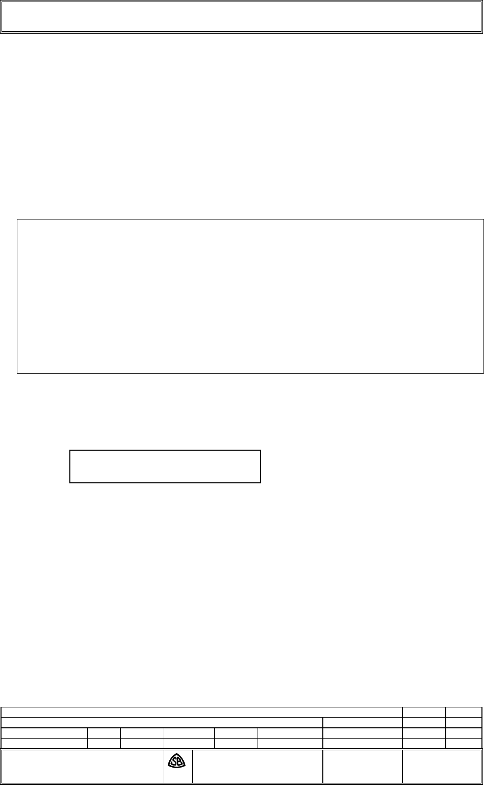
6 FCC/IC information
Important note:
Changes or modifications not expressly
approved by the party responsible
for compliance could void the
user’s authority to operate the equipment.
The device is labelled as follows:
This device complies with part 15 of the FCC and Industry Canada Rules.
Operation is subject to the following two conditions:
(1) This device may not cause harmful interference, and
(2) this device must accept any interference received,
including interference that may cause undesired operation.
Le présent appareil est conforme aux CNR d'Industrie Canada applicables aux appareils radio
exempts de licence. L'exploitation est autorisée aux deux conditions suivantes : (1) l'appareil ne
doit pas produire de brouillage, et (2) l'utilisateur de l'appareil doit accepter tout brouillage
radioélectrique subi, même si le brouillage est susceptible d'en compromettre le fonctionnement.
The device, that contains the SCR module, is labelled outside the device referring to the enclosed
module.This exterior label can use wording such as the following:
Any similar wording that expresses the same meaning may be used.
Contains FCC ID: O5K-SCR
Contains IC ID: 8312A-SCR