Scheidt and Bachmann SCR2 RFID interface module User Manual zur Erstellung von Dokumenten
Scheidt & Bachmann GmbH RFID interface module zur Erstellung von Dokumenten
Integration guide

1 of 6
O5K-SCR2_Integration_Guide - 000104.doc
Integration guide for
Scheidt & Bachmann
Smartcard Reader 2.0
2 of 6
O5K-SCR2_Integration_Guide - 000104.doc
Table of contend
Integration guide for Scheidt & Bachmann Smartcard Reader 2.0 __________________ 1
Revisions __________________________________________________________________ 2
1 The Module ___________________________________________________________ 3
1.1 Connections ................................................................................................................ 3
1.2 Interfaces .................................................................................................................... 4
1.3 Environmental conditions .......................................................................................... 4
2 Power supply __________________________________________________________ 4
3 Antennas ______________________________________________________________ 4
4 Compliance statements __________________________________________________ 5
5 Certification ___________________________________________________________ 5
5.1 FCC (USA) ................................................................................................................. 5
5.2 IC (Canada) ................................................................................................................ 6
6 Contact _______________________________________________________________ 6
Revisions
Version:
Bearbeiter:
Datum:
Abteilung:
Grund:
00.01.00
Nils Hündgen
28.07.2017
GSHW
Erstellung
00.01.01
Nils Hündgen
15.08.2017
GSHW
Corrections
00.01.02
Nils Hündgen
13.09.2017
GSHW
Updated Statements for
documentation
00.01.03
Nils Hündgen
13.09.2017
GSHW
Corrections in Chapter 5
00.01.04
Nils Hündgen
27.10.2017
GSHW
Update PMN
3 of 6
O5K-SCR2_Integration_Guide - 000104.doc
1 The Module
Product Marketing Name: Smartcard Reader 2.0
HVIN: 03740300
FVIN: 07337130
FCC ID: O5K-SCR2
IC: 8312A-SCR2
1.1 Connections
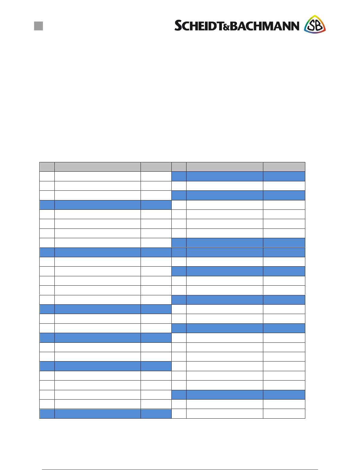
Pinning of the 52 pin PCIe Edge Connector (ST1)
PIN
Description
Netlabel
PIN
Description
Netlabel
1
Trace Clock (Trace Debug Port)
Trace_CLK
27
Ground
GND
2
3.3 V DC Input
+3V3
28
+5V Input (buffered by GoldCap)
+5V_RTC_BATT
3
Trace Data 0 (Trace Debug Port)
Trace_D0
29
Ground
GND
4
Ground
GND
30
Universal I²C Bus Clock
TWCK2
5
Trace Data 1 (Trace Debug Port)
Trace_D1
31
SAM4 ISO 7816 I/O
IO4
6
+5 V DC Input
+5V
32
Universal I²C Bus Data
TWD2
7
Trace Data 2 (Trace Debug Port)
Trace_D2
33
JTAGSEL
JTAGSEL
8
SAM 3 card supply
VCC3
34
Ground
GND
9
Ground
GND
35
Ground
GND
10
SAM3 ISO 7816 I/O
IO3
36
USB signal D-
USB_DATA_N
11
Trace Data 3 (Trace Debug Port)
TRACE_D3
37
Ground
GND
12
SAM3 ISO 7816 CLK
CLK3
38
USB signal D+
USB_DATA_P
13
JTAG TST
TST
39
5V DC supply input
+5V
14
SAM3 ISO 7816 RESET
RST3
40
Ground
GND
15
Ground
GND
41
3.3 V DC supply input
+3V3
16
PD0 ATSAME70 JTAG Compliance Pin
PD0
42
Digital I/O to control a piezo buzzer
BUZZER
17
VBUS Detect
VBUS
43
Ground
GND
18
Ground
GND
44
RXD UART0
Boot_TTL_RXD
19
SAM4 card supply
VCC4
45
JTAG TDI
TDI
20
ERASE Input (reinitialising of Flash)
ERASE
46
TXD UART0
Boot_TTL_TXD
21
Ground
GND
47
JTAG TMS
TMS
22
Reset ATSAME70 (Active-low)
NRST
48
5V DC supply input
+5V
23
SAM4 ISO 7816 RESET
RST4
49
JTAG TCK
TCK
24
3.3 V DC supply input
+3V3
50
Ground
GND
25
SAM4 ISO 7816 CLK
CLK4
51
JTAG TDO
TDO
26
Ground
GND
52
3.3V DC supply input
+3V3

4 of 6
O5K-SCR2_Integration_Guide - 000104.doc
1.2 Interfaces
The main communication Interface to the Host system is USB 2.0. Make sure that
requirements made by the USB-Standard are considered.
1.3 Environmental conditions
Temperature:
• Operating temperature: -25 to +60°C
• Storage temperature: -30 to +60°C
Humidity:
• 5% to 95% not condensing.
The module is sensitive to ESD. Take care while handling these modules.
2 Power supply
Supply voltage for digital circuits: 3.3V +/-5%.
Make sure the voltage is accurate. Good filter practice has to be used.
RF Supply voltage: 5V +/-5%.
Make sure the voltage is accurate. Good filter practice has to be used.
RFID systems require a very high level supply quality. Use linear regulators with high
precision and high control speed whenever possible. When using switching power supplies
make sure the switching speed is above 500 kHz and use an EMC optimized layout as well as
shielded inductors.
The voltage for digital circuits should be applied first.
Current consumption:
Max. 300mA at 3.3V.
Max. 800mA at 5V.
3 Antennas
There are two RF paths with different antenna connectors. That ensures the right connections
for antenna installation.
Antennas made by the grantee used for this certification are the only Antennas which should
be used in combination with the device.
The antenna of the module should not be removed, replaced nor modified. The antenna must
not be co-located or operating in conjunction with any other antenna or transmitter within
20cm. No other antenna than the ones from the certification must be used.

5 of 6
O5K-SCR2_Integration_Guide - 000104.doc
4 Compliance statements
In the manual of the host product the following statements have to be written in a prominent
location:
NOTE: This equipment has been tested and found to comply with the limits for a Class B digital
device, pursuant to Part 15 of the FCC Rules. These limits are designed to provide reasonable
protection against harmful interference in a residential installation. This equipment generates, uses
and can radiate radio frequency energy and, if not installed and used in accordance with the
instructions, may cause harmful interference to radio communications. However, there is no guarantee
that interference will not occur in a particular installation. If this equipment does cause harmful
interference to radio or television reception, which can be determined by turning the equipment off and
on, the user is encouraged to try to correct the interference by one or more of the following measures:
Reorient or relocate the receiving antenna.
Increase the separation between the equipment and receiver.
Connect the equipment into an outlet on a circuit different from that to which the receiver is
connected.
Consult the dealer or an experienced radio/TV technician for help.
This device complies with Part 15 of the FCC Rules and with Industry Canada licence-exempt RSS
standard(s).Operation is subject to the following two conditions:
1. This device may not cause harmful interference, and
2. This device must accept any interference received, including interference that may cause
undesired operation.
Le présent appareil est conforme aux CNR d'Industrie Canada applicables aux appareils radio
exempts de licence. L'exploitation est autorisée aux deux conditions suivantes:
1. l'appareil ne doit pas produire de brouillage, et
2. l'utilisateur de l'appareil doit accepter tout brouillage radioélectrique subi, même si le
brouillage est susceptible d'en compromettre le fonctionnement.
NOTICE:
Changes or modifications made to this equipment not expressly approved by
(Scheidt & Bachmann GmbH) may void the FCC authorization to operate this equipment.
5 Certification
5.1 FCC (USA)
The FareGo SCR Module complies with Part 15 of the FCC Rules. To fulfill all FCC
requirements the integrator must comply with the following regulations:
- The integrator must make sure that the end device is labeled according to FCC
requirements. This means that the end device must have a clearly visible label on the
outside of the product with at least the following content:
Contains FCC ID: O5K-SCR2
This device complies with Part 15 of the FCC Rules. Operation is subject to the
following two conditions: (1) this device may not cause harmful interference, and

6 of 6
O5K-SCR2_Integration_Guide - 000104.doc
(2) this device must accept any interference received, including interference that
may cause undesired operation.
- The integrator must test the final product to comply with FCC regulations regarding
unintentional radiators (FCC section 15.107 and 15.109) before declaring FCC
compliance of his own product.
ATTENTION:
Changes or modifications not expressly approved by Scheidt & Bachmann GmbH could
void the user’s authority to operate the equipment.
5.2 IC (Canada)
Labeling requirements for Industry Canada (IC) are similar to those of the FCC. A clearly
visible label on the outside of the final product must display at least the following text:
Contains Model QR15 RFID Module, IC: 8312A-SCR2
The integrator is responsible for its product to comply with IC ICES-003 & FCC Part 15, Sub.
B - Unintentional Radiators. ICES-003 is the same as FCC Part 15 Sub. B and Industry
Canada accepts FCC test report or CISPR 22 test report for compliance with ICES-003.
6 Contact
Scheidt & Bachmann GmbH
Breite Str. 132
41238 Mönchengladbach
Germany
Tel.: +49 (0)2166 / 266 – 0
www.scheidt-bachmann.com