Scheidt and Bachmann TRACO Transponder Controller Module User Manual ChipCoin Processing
Scheidt & Bachmann GmbH Transponder Controller Module ChipCoin Processing
Contents
- 1. user manual
- 2. user manual II
user manual
ChipCoin® Processing
Car Park Management System PMS20
Manual ChipCoin Processing
GmbH, Mönchengladbach (Germany)
strations and descriptions may also include special options.
PMS/C
ChipCoin® Processing
Systems for Car Parks and Leisure Centres
Article no. of chapter: 86 93538 (d) 1
© 2004 by Scheidt & Bachmann
All rights reserverd. Subject to alterations. Some Illu
- Service Manual -

ChipCoin® Processing
Car Park Management System PMS20
Manual ChipCoin Processing
Article no. of chapter: 86 93538 (d) 1
© 2004 by Scheidt & Bachmann GmbH, Mönchengladbach (Germany)
All rights reserverd. Subject to alterations. Some Illustrations and descriptions may also include special options.
Contents Page
1. Introduction..........................................................................................2
1.1. Block diagram .......................................................................................... 2
2. Coin feeder ...........................................................................................3
2.1. Entry.......................................................................................................... 3
2.1.1. Function ................................................................................................... 3
2.2. Exit ............................................................................................................ 4
2.2.1. Function ................................................................................................... 4
2.3. Automatic Pay Station............................................................................. 5
2.3.1. Function ................................................................................................... 5
2.4. Maintenance and service......................................................................... 6
2.4.1. Outside .................................................................................................... 6
2.4.2. Inside ....................................................................................................... 7
3. Entry hopper.........................................................................................8
3.1. View........................................................................................................... 8
3.2. Maintenance and service......................................................................... 9
4. ChipCoin interface.............................................................................10
4.1. View / connections................................................................................. 10
5. PIT Base station.................................................................................11
5.1. View / connections................................................................................. 12
6. Item numbers .....................................................................................12
ChipCoin® Processing
Car Park Management System PMS20
ChipCoin Processing Manual
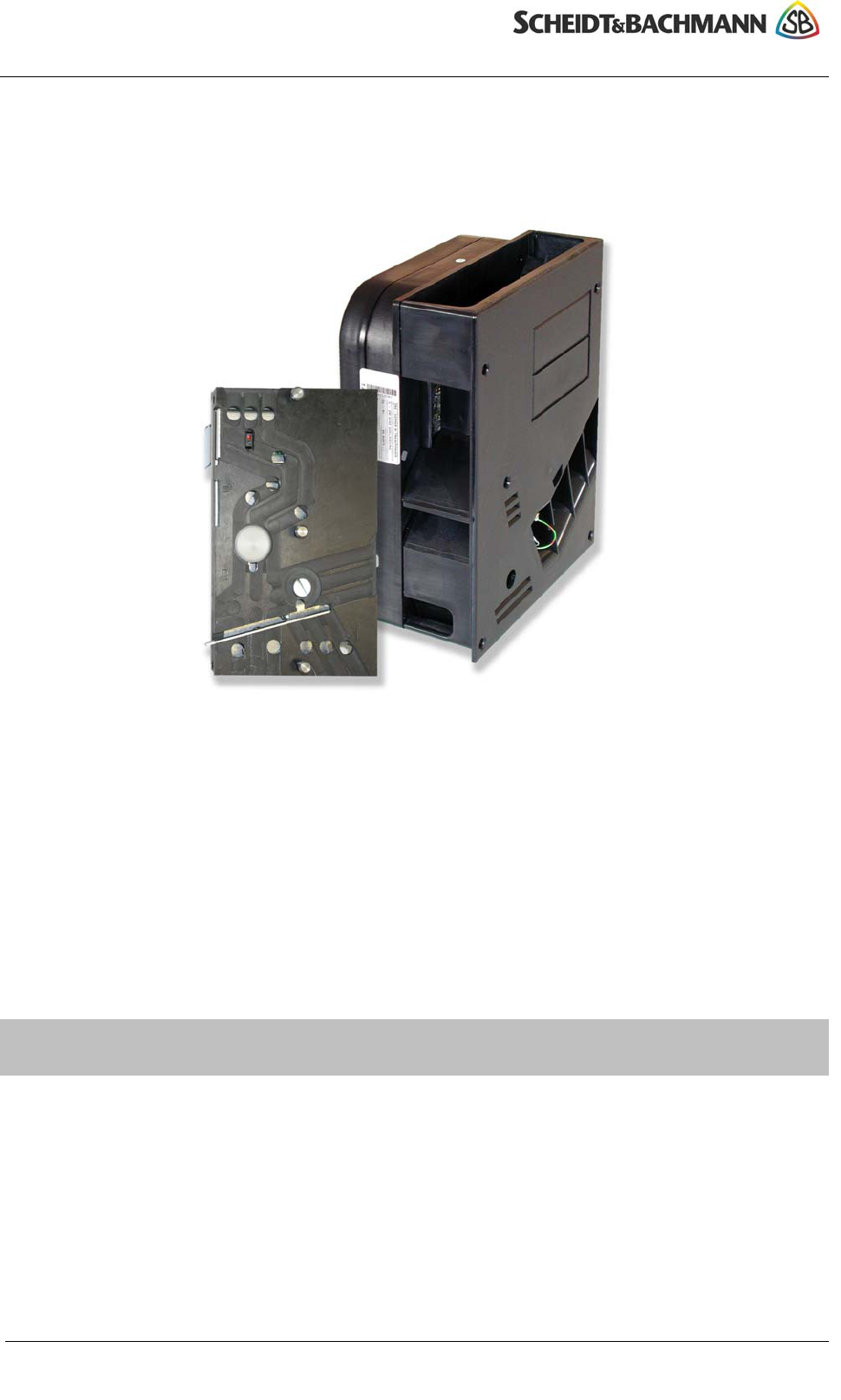
1. Introduction
At an entry the coin feeder is located directly in front of the hopper. In case of a
ChipCoin request the coin goes from the hopper to the coin feeder, where it is
guided through the coin channel via stopper and reject magnets and coded and
read by an installed antenna coil.
At an exit the ChipCoin inserted by the customer goes directly into the coin feeder.
Here it is read via the antenna coil and, when found to be valid, is moved on to the
collector receptacle; the gate opens. ChipCoins without exit authorisation are
returned via a reject mechanism to be removed by the customer.
At an automatic pay machine the ChipCoin inserted by the customer likewise
goes directly to the coin feeder. It is read via the antenna coil and "parked" there as
long as necessary until the customer has paid the fee calculated. Simultaneous to
that the insertion aperture of the coin channel (shutter) closes in order to prevent
insertion of coins into the coin feeder.
Due to the different demands (with shutter, without shutter, different coin inlet)
different coin feeders are used for entrance, exit and automatic teller.
2 Article no. of chapter: 86 93538 (d)
© 2004 by Scheidt & Bachmann GmbH, Mönchengladbach (Germany)
All rights reserverd. Subject to alterations. Some Illustrations and descriptions may also include special options.
All versions are based on identical coin channels (black coin feeder casing)
which are varyingly fitted with magnets, reflex couplers and mechanical
components.
First of all the different versions and their functional operation will be explained.
Maintenance tips will be given on the basis of a fully outfitted coin channel.
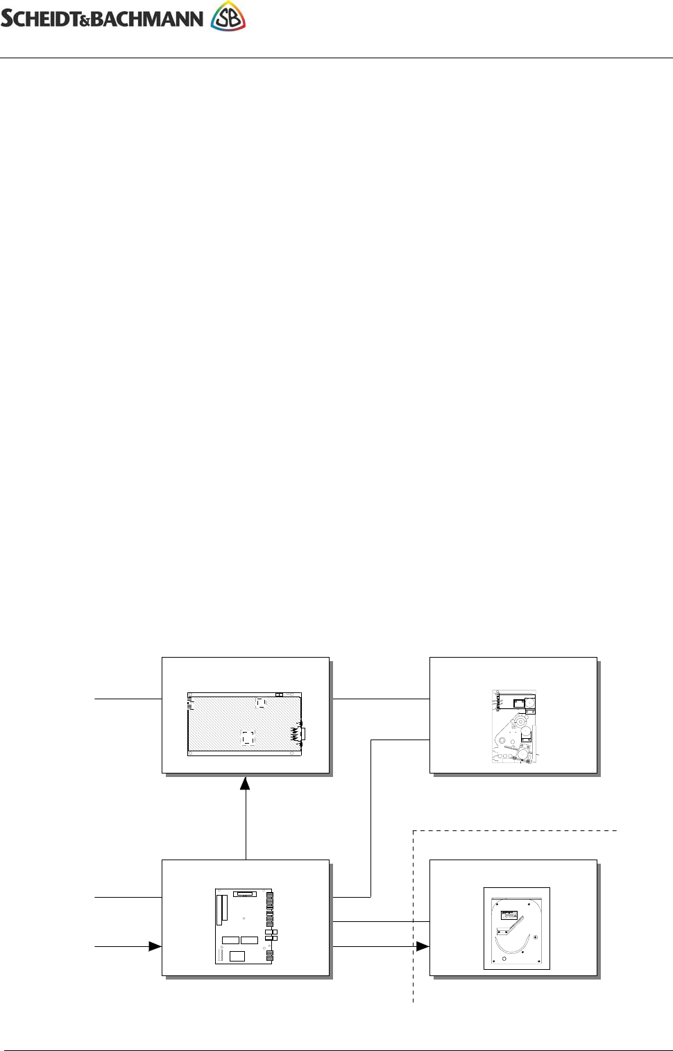
1.1. Block diagram
PIT Basestation
I/O
COM1/EPR
12V
I/Os
I/Os
ChipCoin Interface Hopper
Power supply Power
Antennas
Coin feeder
Entry only
ChipCoin® Processing
Car Park Management System PMS20
Manual ChipCoin Processing
2. Coin feeder
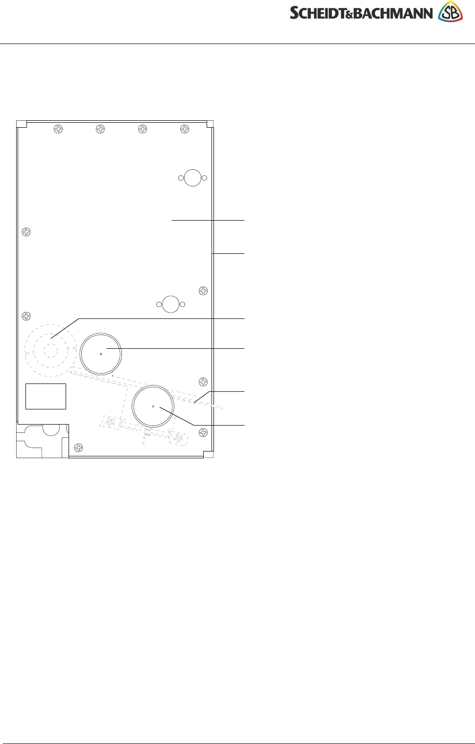
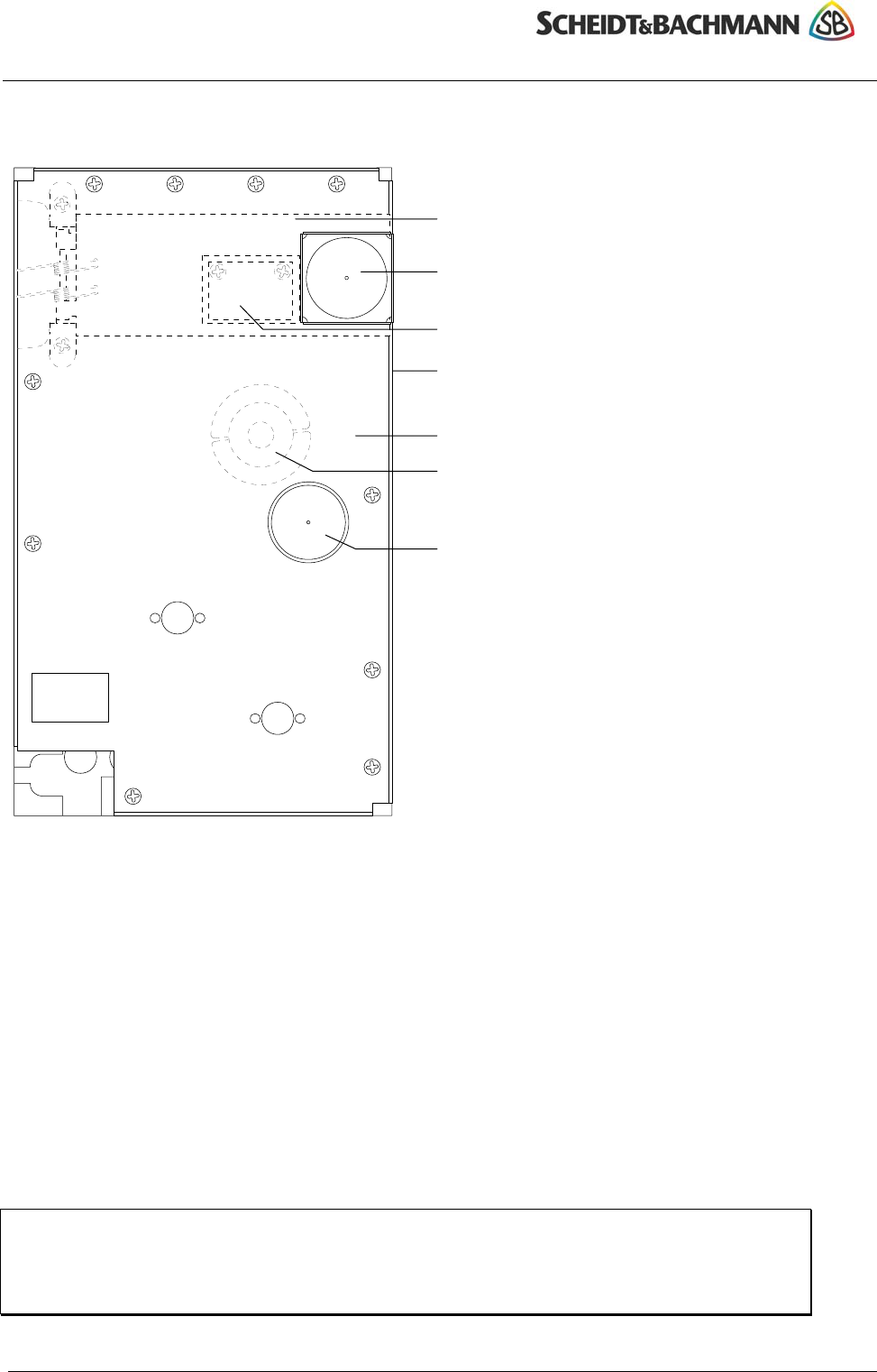
2.1. Entry
Article no. of chapter: 86 93538 (d) 3
© 2004 by Scheidt & Bachmann GmbH, Mönchengladbach (Germany)
All rights reserverd. Subject to alterations. Some Illustrations and descriptions may also include special options.
Mounting plate
Coin channel
(covered by mounting plate)
Read/write antenna
Stopper magnet for
read/write operation
Reject plate for ChipCoins
not removed
Reject magnet for ChipCoins
not removed
2.1.1. Function
As soon as a vehicle drives over the loop, the ChipCoin, which has already been
positioned by the stopper magnet in front of the read/write antenna, is coded.
After pressing the ChipCoin request button the stopper magnet is pulled tight and
the ChipCoin is thereby released for output.
If the ChipCoin cannot be coded, the stopper magnet and the reject magnet pull
tight and the ChipCoin falls into the collector receptacle.
If the ChipCoin is not removed within a predefined period of time, the stopper
magnet pulls tight and the coin is dropped into the collector receptacle.
After removing the coded ChipCoin a new ChipCoin is brought into position in front
of the read/write antenna.
ChipCoin® Processing
Car Park Management System PMS20
ChipCoin Processing Manual
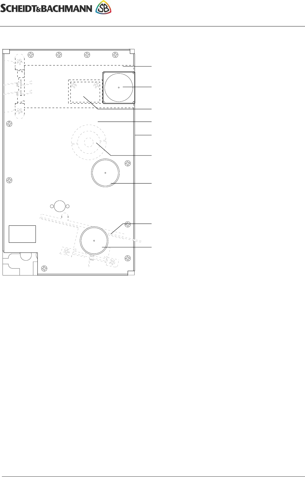
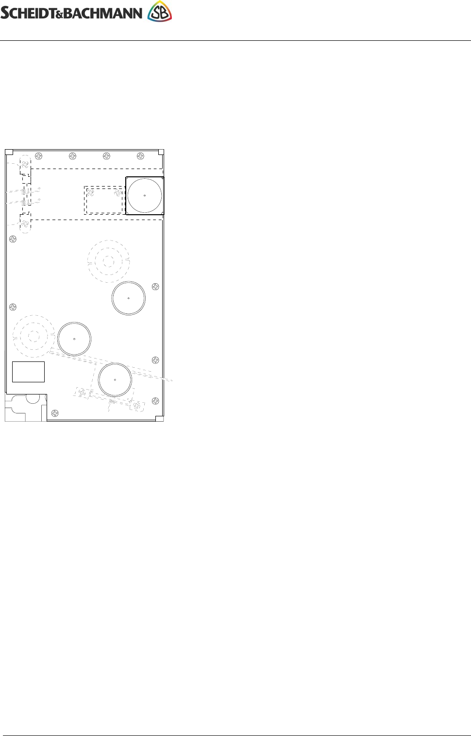
2.2. Exit
4 Article no. of chapter: 86 93538 (d)
© 2004 by Scheidt & Bachmann GmbH, Mönchengladbach (Germany)
All rights reserverd. Subject to alterations. Some Illustrations and descriptions may also include special options.
Shutter flap
Shutter magnet
Reflex coupler circuit board
Mounting plate
Coin channel
(covered by mounting plate)
Read/write antenna
Stopper magnet for
read/write operation
Reject plate for invalid ChipCoins
Reject magnet for invalid ChipCoins
2.2.1. Function
The shutter releases the ChipCoin insert chute if a vehicle is on the loop. In this
way insertion of foreign matter by pedestrians (vandalism) is prevented.
In standard position the shutter is closed, the stopper magnet blocks the ChipCoin
and the rejector plate stands in the "Reject coin" position (output to the front).
If the loop is driven over, the shutter is opened. (Magnet pulls tight). The ChipCoin
is inserted and is blocked at the read/write antenna by the stopper magnet. The
ChipCoin is analysed.
If it entitles the holder to exit, the stopper magnet and the reject magnet pull tight.
The ChipCoin falls into the exit collector receptacle and the gate is opened.
If the ChipCoin is invalid (eg, the period of grace is exceeded; supplemental
payment) the stopper magnet pulls tight and the ChipCoin is outputted to the front
via the reject plate. The gate does not open. The reason for this is shown to the
customer on the display.
ChipCoin® Processing
Car Park Management System PMS20
Manual ChipCoin Processing
2.3. Automatic Pay Station
Article no. of chapter: 86 93538 (d) 5
© 2004 by Scheidt & Bachmann GmbH, Mönchengladbach (Germany)
All rights reserverd. Subject to alterations. Some Illustrations and descriptions may also include special options.
Shutter flap
Shutter magnet
Read/write antenna
Reflex coupler circuit board
Stopper magnet for
read/write operation
Coin channel
(covered by mounting plate)
Mounting plate
2.3.1. Function
At the automatic teller the shutter closes upon insertion of a ChipCoin and thereby
prevents the customer from inserting coins into the coin feeder.
In standard condition the shutter is opened and the stopper magnet blocks the
ChipCoin.
If the customer has inserted the ChipCoin for analysis, this is recognised by the
reflex coupler and the shutter is closed (the magnet drops down). The ChipCoin is
positioned in front of the read/write antenna by the stopper magnet. The amount to
be paid is determined and displayed.
When the payment operation is completed, the authorisation to exit is coded on the
ChipCoin and the stopper magnet is briefly pulled tight. The ChipCoin falls into the
return change cup for removal.
Suggestion:
In order to avoid blockage/disturbance by foreign matter (e g, coins), the stopper
magnet at regular intervals pulls tight briefly so that such items are diverted down
into the return change cup.
ChipCoin® Processing
Car Park Management System PMS20
ChipCoin Processing Manual
2.4. Maintenance and service
2.4.1. Outside
The small number of movable parts reduces maintenance expense to the coin
feeder to a minor level. The following suggestions should, however, be heeded in
order to ensure permanent faultfree operations.
6 Article no. of chapter: 86 93538 (d)
© 2004 by Scheidt & Bachmann GmbH, Mönchengladbach (Germany)
All rights reserverd. Subject to alterations. Some Illustrations and descriptions may also include special options.
c Shutter plate
d Shutter magnet
e Stopper magnet (exit, automatic pay station)
f Stopper magnet (entry)
g Reject magnet
h Reject plate
i Read/write antenna (exit, automatic pay
station)
j Read/write antenna (entry)
k Reflex coupler circuit board
l Springs for shutter, rejector plate
c
d
l k
i
e
j f
g
h
l
• The entire coin feeder should be checked on both inside and outside for dirt and,
if necessary, should be cleaned. Be careful, in doing so, of the shutter and
rejector magnet mechanism (d,g).
• In case of serious dirt accumulation an air pump can be used for cleaning.
• Check for the smooth working of the shutter plate (c) and the reject plate (h).
Only the spring tension (l) should be allowed to show any perceptible
resistance.
• Check for tight fit of the read/write antenna (i,j).
ChipCoin® Processing
Car Park Management System PMS20
Manual ChipCoin Processing
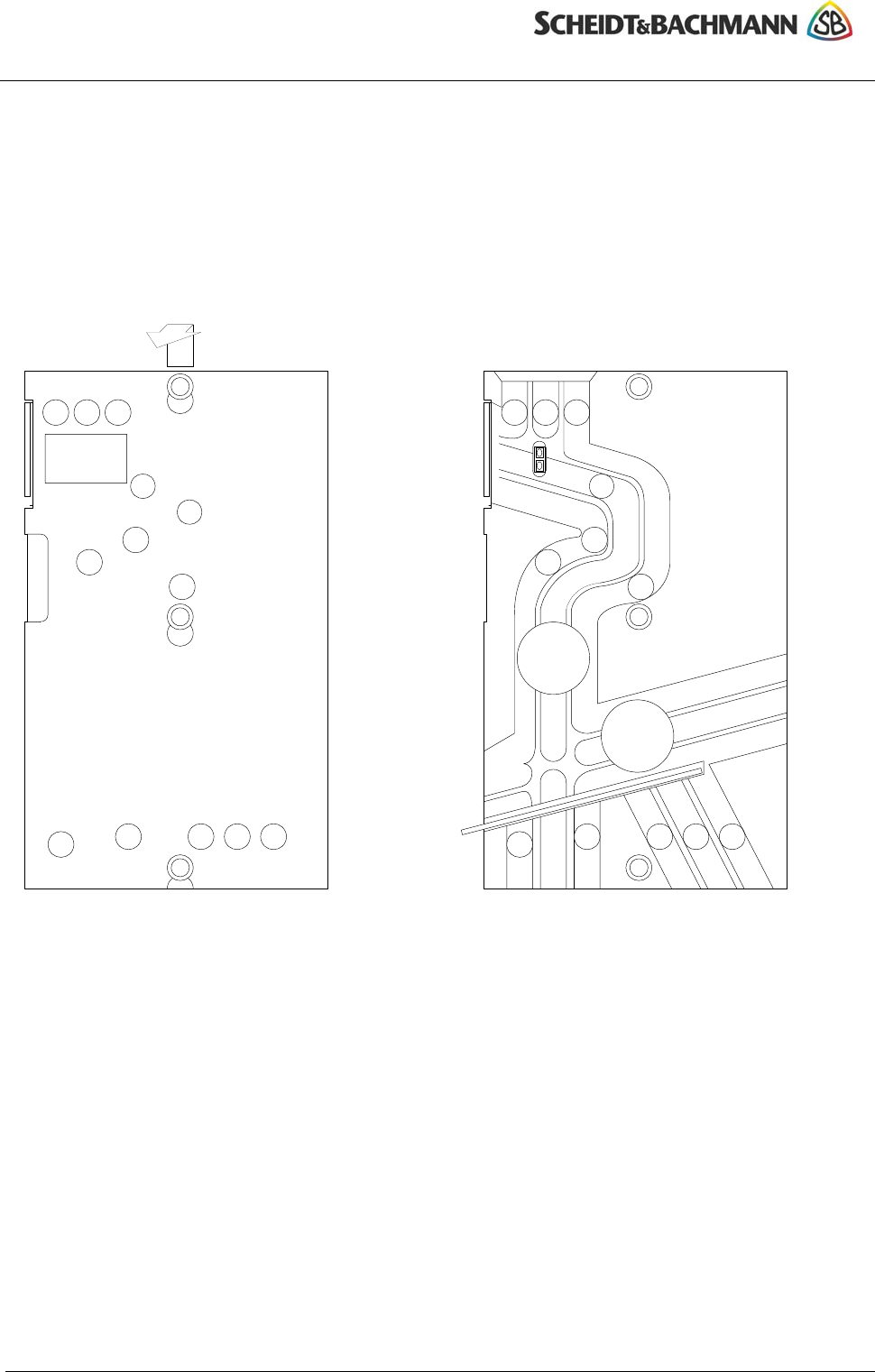
2.4.2. Inside
2.4.2.1. Cover removal
For removal of the cover the coin feeder should be taken out of its bracket.
Coin channel and cover are held together by a bayonet catch. After pushing the
cover upwards it can be removed.
Push cover upwards Coin feeder without the cover
Article no. of chapter: 86 93538 (d) 7
© 2004 by Scheidt & Bachmann GmbH, Mönchengladbach (Germany)
All rights reserverd. Subject to alterations. Some Illustrations and descriptions may also include special options.
i i
c c c ccc
d e
c
c
c
c c
c c
c
c
i i
f
g
h
c c c c c
i
c c c
c c
i
c Condensation openings
d Reflecting sticker for reflect coupler
i Bayonet catch
e Reflex coupler
f Stopper magnet (exit, automatic
pay station)
g Stopper magnet (entry)
h Rejector plate
• Check the sticker (d) for dirt. It must have a light-coloured reflecting surface.
• Check the reflex coupler (e) for dirt.
• For cleaning the coin channel use an air pump, a brush or a soft rag.
• Check to see that the stopper magnets (f,g) work smoothly. They must let
themselves be pressed in easily upon pressure from the encapsulated spiral
spring. Under no circumstances may they be hard to move, nor should they stick
tight.
ChipCoin® Processing
Car Park Management System PMS20
ChipCoin Processing Manual
3. Entry hopper
The entrance hopper stores the ChipCoins and conveys them to the coin feeder. In
order to increase its capacity and to make refilling easier, a funnel has been
mounted on top of the hopper. In order to check the supply of ChipCoins, the funnel
has been provided with viewing holes.
Control and voltage supply occur via a connection to the ChipCoin interface.
Coin output occurs via a chain. In order to ensure that the coins reach the right
properly start-position for transport via the chain, with every movement of the chain
there occurs additionally the movement of one of the slides driven by an eccentric.
Both the chain and the slide are driven by the same motor.
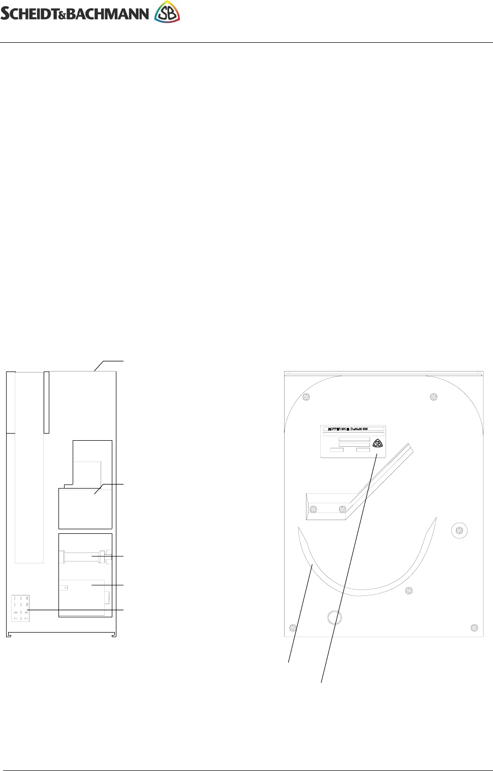
3.1. View
Front view Side view
8 Article no. of chapter: 86 93538 (d)
© 2004 by Scheidt & Bachmann GmbH, Mönchengladbach (Germany)
All rights reserverd. Subject to alterations. Some Illustrations and descriptions may also include special options.
Connection plug for
ChipCoin interface
Drive motor
Sliding shaft
Funnel receptacle /
ChipCoin input
ChipCoin exit to coin feeder
ChipCoin drive track
Name plate

ChipCoin® Processing
Car Park Management System PMS20
Manual ChipCoin Processing
3.2. Maintenance and service
The hopper is maintenance-free. Should it ever occur that, despite plentiful supply
of coins, no ChipCoin is outputted, then possibly a jam may have occurred.
Check to see if the hopper upon a ChipCoin request makes a short movement. If
this is the case and no jam obtains in the coin feeder, then take the hopper out and
empty it. Jams can normally be eliminated by shaking the hopper. You will hear if
the ChipCoin releases. Then fill the hopper again and put it back in. Turn the
entrance on again and check its functioning.
Never work on the hopper with the current turned on. First turn
the entrance off and then remove the plug from the hopper.
Article no. of chapter: 86 93538 (d) 9
© 2004 by Scheidt & Bachmann GmbH, Mönchengladbach (Germany)
All rights reserverd. Subject to alterations. Some Illustrations and descriptions may also include special options.
ChipCoin® Processing
Car Park Management System PMS20
ChipCoin Processing Manual
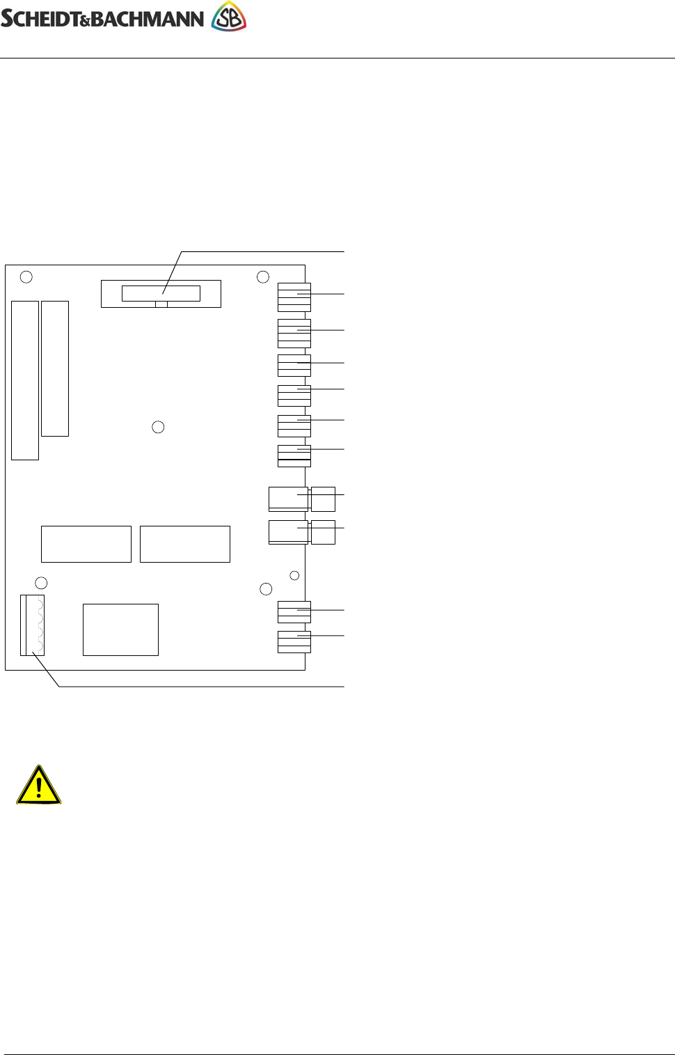
4. ChipCoin interface
The Chip-Coin interface circuit board assumes control of the stopper, shutter and
rejector magnets as well as analysis of information from the reflex coupler and the
photoelectric barrier as well as hopper control.
4.1. View / connections
10 Article no. of chapter: 86 93538 (d)
© 2004 by Scheidt & Bachmann GmbH, Mönchengladbach (Germany)
All rights reserverd. Subject to alterations. Some Illustrations and descriptions may also include special options.
Reserve
Reflex coupler (entrance, automatic pay station)
Stopper magnet (entry)
Shutter magnet (exit, automatic pay station)
Rejector magnet (entry / exit)
Stopper magnet (exit, automatic pay station)
LW connection for luminous diode
LW connection for phototransistor
Reserve
Current output for PIT base station
Hopper connection (entrance)
Current supply
Never work on the circuit board when the current is on. First turn
off the device and wait until it has come to a complete rest.

ChipCoin® Processing
Car Park Management System PMS20
Manual ChipCoin Processing
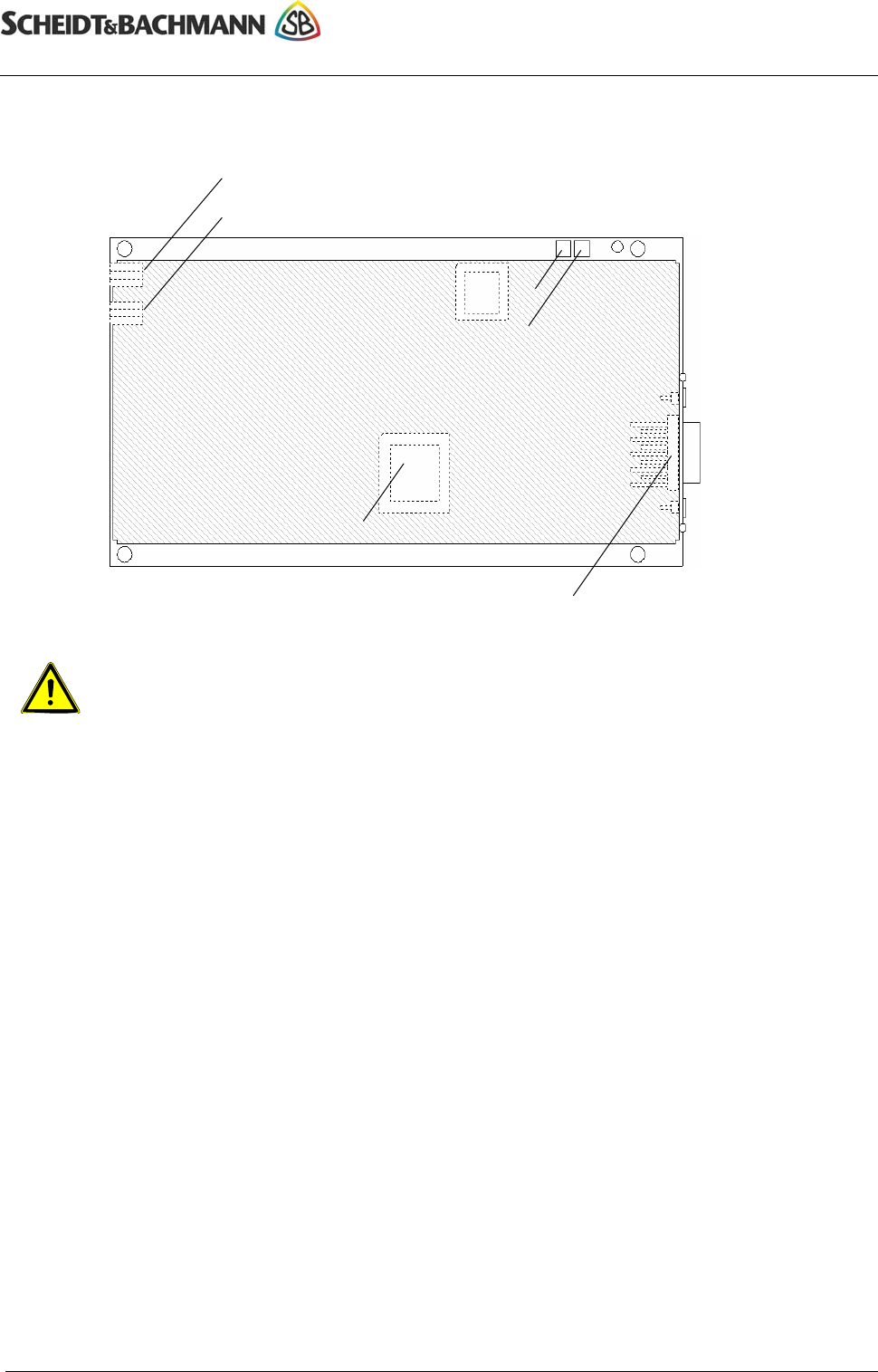
5. PIT Base station
The PIT base station III is the interface for coding and analysis of the ChipCoin
cards. It has a serial interface for connection to the single-board computer or the
PMK computer as well as having two antenna connections.
Article no. of chapter: 86 93538 (d) 11
© 2004 by Scheidt & Bachmann GmbH, Mönchengladbach (Germany)
All rights reserverd. Subject to alterations. Some Illustrations and descriptions may also include special options.
This equipment has been tested and found to comply with the limits for
a Class B digital device, pursuant to Part 15 of the FCC Rules. These
limits are designed to provide reasonable protection against harmful
interference in a residential installation. This equipment generates, uses
and can radiate radio frequency energy and, if not installed and used in
accordance with the instructions, may cause harmful interference to
radio communications. However, there is no guarantee that interference
will not occur in a particular installation. If this equipment does cause
harmful interference to radio or television reception, which can be
determined by turning the equipment off and on, the user is encouraged
to try to correct the interference by one or more of the following
measures:
• Reorient or relocate the receiving antenna.
• Increase the separation between the equipment and receiver.
• Connect the equipment into an outlet on a circuit different from that
to which the receiver is connected.
• Consult the dealer or an experienced radio/TV technician for help.
Changes and modifications not expressly approved by Scheidt &
Bachmann can void the user's authority to operate the equipment.
ChipCoin® Processing
Car Park Management System PMS20
ChipCoin Processing Manual
5.1. View / connections
12 Article no. of chapter: 86 93538 (d)
© 2004 by Scheidt & Bachmann GmbH, Mönchengladbach (Germany)
All rights reserverd. Subject to alterations. Some Illustrations and descriptions may also include special options.
ChipCoin read/write antenna (inside, coin feeder)
Serial interface (Ö COM1)
Operational readiness, green
Card read/write antenna (outside)
Analysis operation, red
Flash PROM (software)
Never work on the circuit board when the current is on. First turn
off the device and wait until it has come to a complete rest.
6. Item numbers
PIT Base station III............................ 04 19275
ChipCoin Interface............................. 04 18306
Entry hopper (bulk coin store) ........... 04 18112
Entry coin feeder ............................... 04 17845
Exit coin feeder ................................. 04 17844
Automatic Pay Station feeder............ 04 18117