Schlage Electronic Security RDR-ICL Door Lock with Proximity Reader Transmitter User Manual 409902F3 5CB7 206B76
Schlage Electronic Security Door Lock with Proximity Reader Transmitter 409902F3 5CB7 206B76
UserManual.wiki
>
Schlage Electronic Security
>
RDR ICL User Manual
User Manual
Navigation menu
Upload a User Manual
Namespaces
Wiki Guide
HTML
PDF
Info
Views
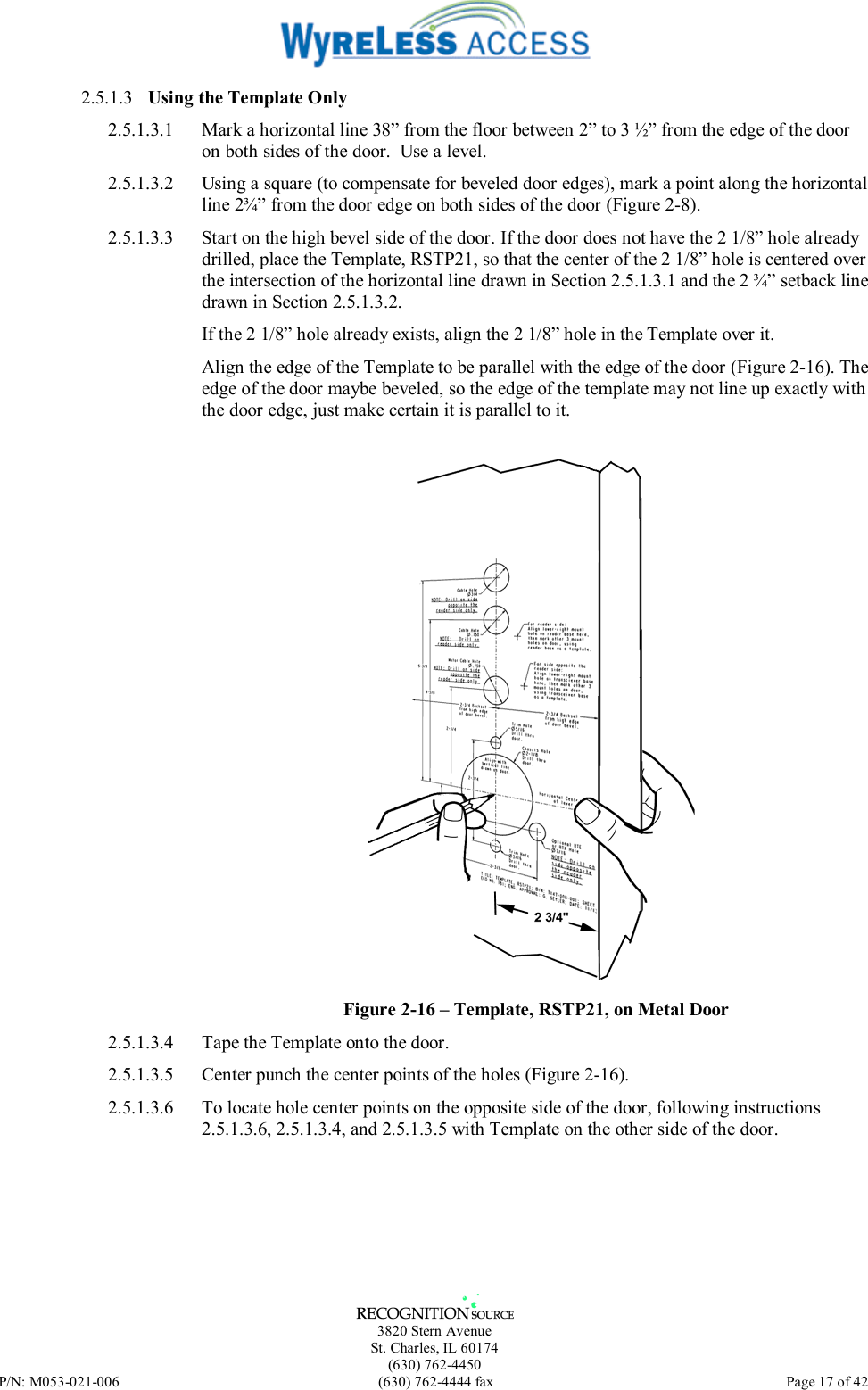
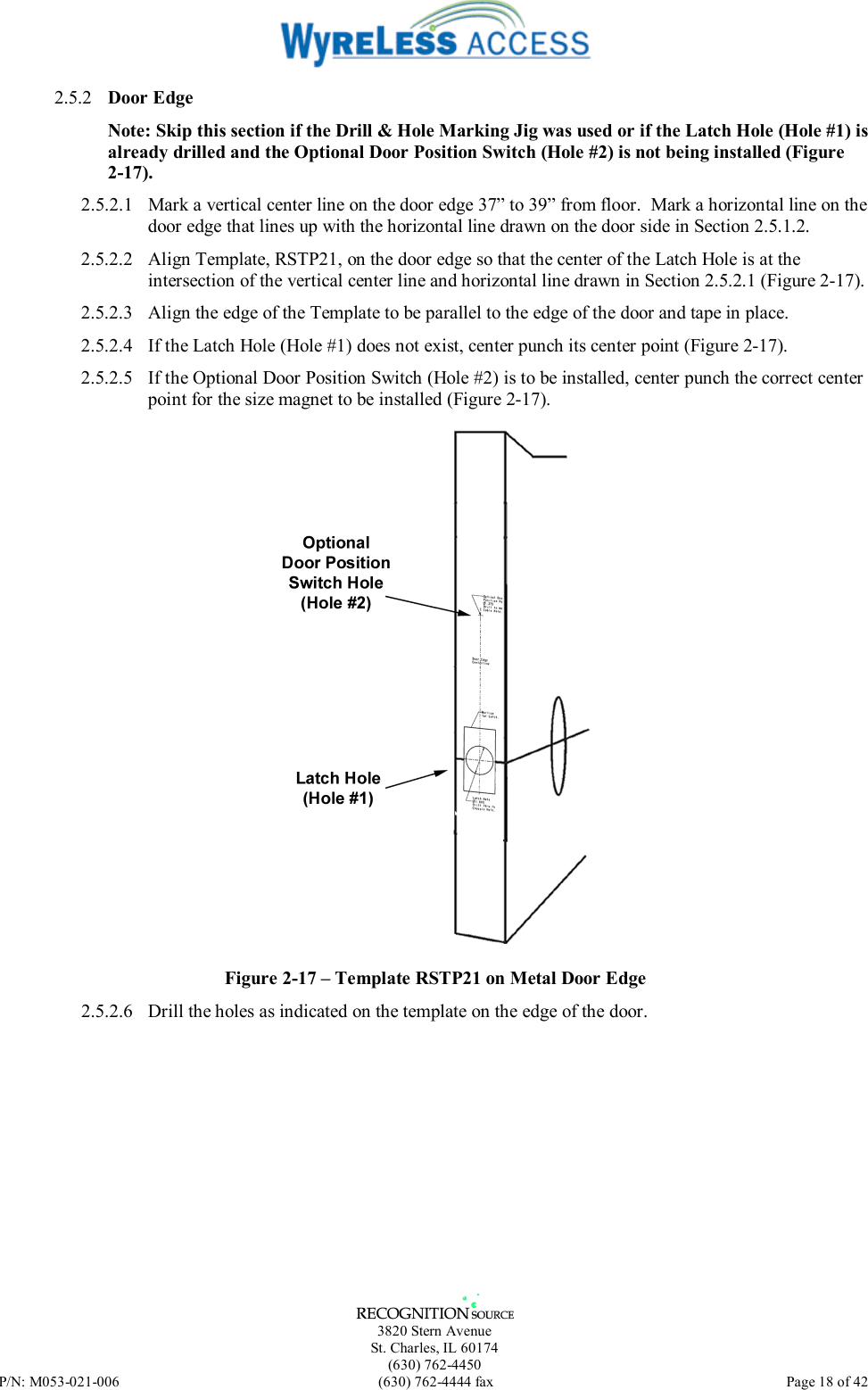
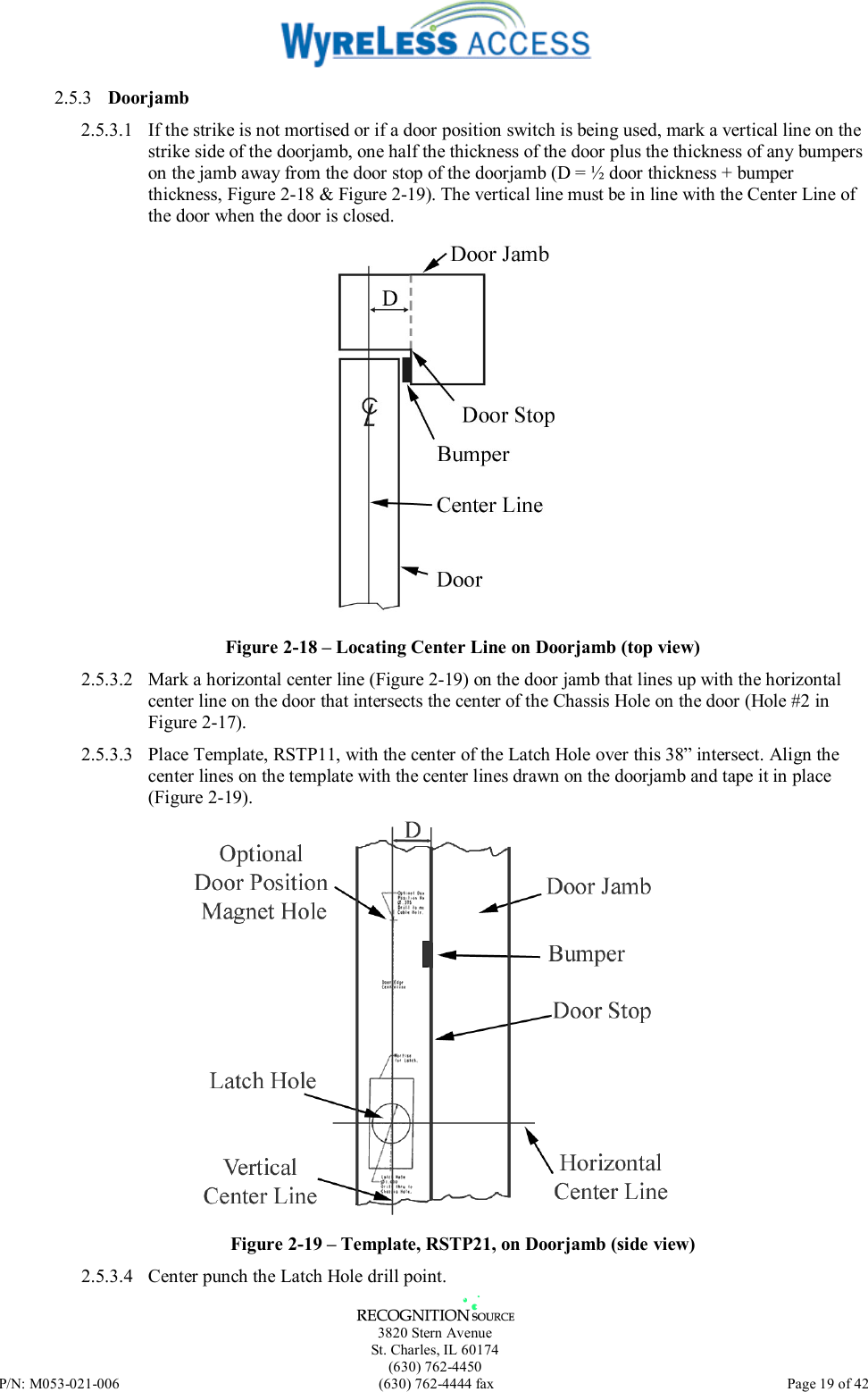
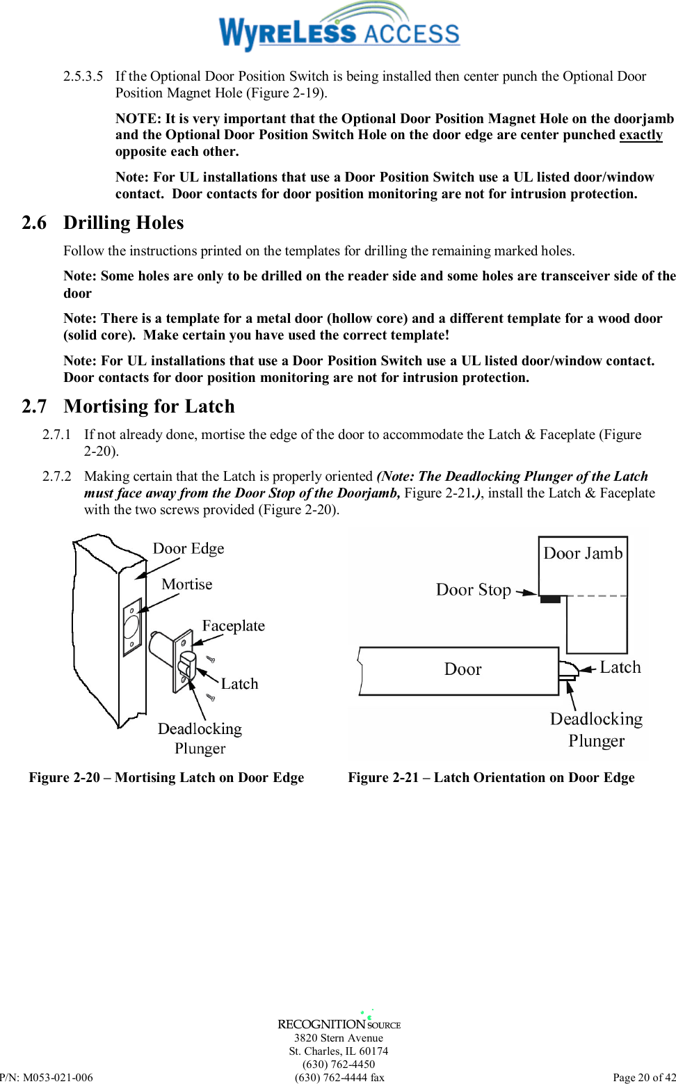
User Manual
Discussion / Help
Navigation