Schlage Lock ADMULTI Proximity/Smartcard Reader User Manual P516 098 WPR Rev a 17 indd
Schlage Lock Company Proximity/Smartcard Reader P516 098 WPR Rev a 17 indd
User Manual
P516-098
WIRELESS PORTABLE READER (WPR)
INSTRUCTIONS FOR WPR400
Para el idioma español, navegue hacia www.schlage.com/support.
Pour la portion française, veuillez consulter le site www.schlage.com/support.

2
WPR-400 Wireless Portable Reader User Guide
CONTENTS
Overview ........................................................................................................................................ 3
Getting Started .............................................................................................................................. 3
WPR400 Operation ....................................................................................................................... 4
WPR400 Range ........................................................................................................................ 4
Connecting a Reader to the WPR400 ....................................................................................... 4
Connecting the RF Board to the Main Board ............................................................................ 5
Permanently or Temporarily Mounting the WPR400 .................................................................. 5
Handheld Device (HHD) ................................................................................................................ 6
Linking to a PIM400 (Reader mode only) ...................................................................................... 7
Re-linking The WPR400 ................................................................................................................ 7
Changing the RF Channel ............................................................................................................. 8
Enabling Dynamic Channel Switching ........................................................................................... 8
Resetting To Factory Defaults ........................................................................................................ 9
WPR400 LED Reference ............................................................................................................... 9
Link Mode LED Reference ........................................................................................................9
Normal Operation LED Reference............................................................................................. 9
Test Mode (No Credential Reader required) ................................................................................ 10
Linking to the PIM400-TD2 in Test Mode ................................................................................ 11
Using the WPR400 in Test Mode ............................................................................................. 12
WPR400 Test Mode LED Reference ....................................................................................... 12
Improving RF Communications ............................................................................................... 12
Batteries ...................................................................................................................................... 13
Charging Batteries ................................................................................................................... 13
Installing or Replacing Batteries ..............................................................................................13
Troubleshooting ........................................................................................................................... 14
FCC/IC Statements ..................................................................................................................... 15
www.schlage.com/support
877.671.7011
3
WPR-400 Wireless Portable Reader User Guide
OVERVIEW
The WPR400 is a Wireless Access Point Module (WAPM) designed to interface with access control
panels through a PIM400. The WPR400:
• Communicates with the PIM400 via RF (radio frequency).
• May be linked only to a PIM400.
• Is powered with rechargeable batteries.
• May be used with all credential readers in the AD-Series product line.
• When attached to a credential reader, normally operates in on-line (Reader) mode. Information
contained in the user credentials is passed to an access control panel (ACP), which controls
WPR400 LEDs. The ACP maintains the audit trail.
• May be operated in Tester mode, with or without a credential reader. In Tester mode, the WPR400
continually tests the quality of the RF link with a PIM400.
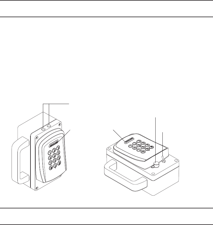
LED Indicators
Schlage Button On/Off Switch
Power Jack
GETTING STARTED
Follow these steps when setting up a WPR400.
1. Install the PIM400 (PIM-TD2 or PIM-485). Refer to the User Guide that came with the PIM400, or
visit www.schlage.com/support, for more information.
2. Make sure PIM400 power is properly connected.
3. The WPR400 is shipped with batteries installed and ready for confi guration. If the batteries need
charging or replacing, please see Batteries on page 13. Make sure batteries are fully charged
before use.
4. Familiarize yourself with the information contained in this user guide.
! Save this user guide for future reference.
4
WPR-400 Wireless Portable Reader User Guide
WPR400 OPERATION
WPR400 Range
For optimum performance, the WPR400 should be operated within the following range limits:
• Maximum distance between the PIM400 and WPR400 is 200 feet (61 meters) horizontally on the
same fl oor in a building with normal construction materials.
• For a line-of-sight installation, maximum distance is 1000 feet (305 meters).
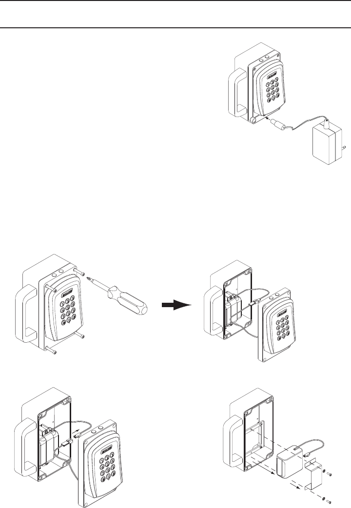
Connecting a Reader to the WPR400
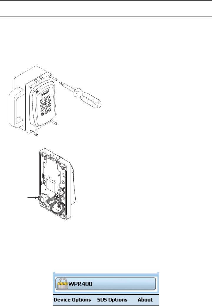
1. Connect the reader cable to the reader as shown below.
2. Secure the reader to the front cover using the screws and washers provided.
1.
Reader
Reader cable
2.
5
WPR-400 Wireless Portable Reader User Guide
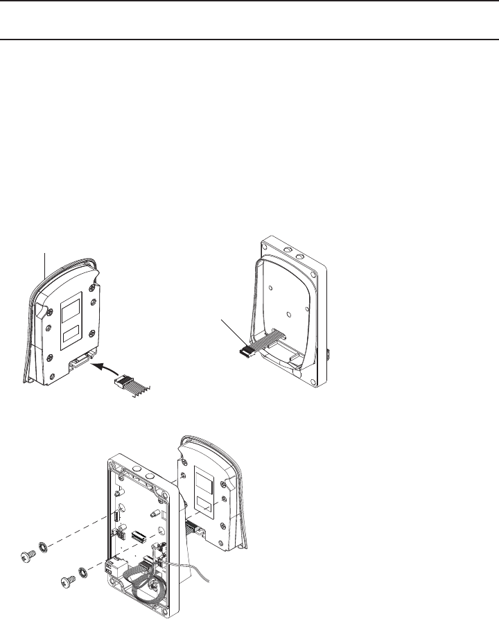
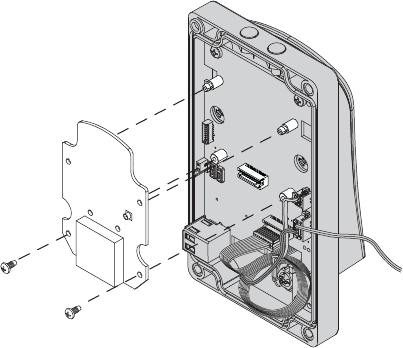
Connecting the RF Board to the Main Board
1. While maintaining a proper electrical connection, push the RF board onto the support posts and
secure with screws provided.
Permanently or Temporarily Mounting the WPR400
• Mount the WPR400 using screws or Velcro® strips.
• The WPR400 should always be mounted at least one inch away from any metallic surface.
• Place the WPR400 in a position where it was successfully link tested.
Permanent mounting with screws:
1. Remove the WPR400 cover.
2. Using the base as a template, mark the mounting holes.
3. Drill a hole at each mark and use a wall anchor and screws (not provided) to attach the WPR400.
4. If mounted on a metallic surface, use one inch non-metallic spacers (not provided).
Temporary mounting with Velcro® strips:
1. Attach adhesive Velcro® strips (“hook” side) to the WPR400’s base.
2. Attach the other adhesive Velcro® strips (“loop” side) to the mounting surface, positioned
according to the placement of strips on the WPR400’s base.
3. Press the WPR400 to the mounting surface with both sets of strips aligned.
6
WPR-400 Wireless Portable Reader User Guide
HANDHELD DEVICE (HHD)
The HHD can be used to confi gure credential reader settings.
For information about the HHD and credential reader settings, see the Schlage Utility Software User
Guide at www.schlage.com/support.
To connect the HHD to the WPR400:
1. Turn off the WPR400 power switch.
2. Loosen the 4 screws and remove the WPR400 cover.
3. Connect the HHD to the WPR400 USB port.
USB Port
4. Log in to the SUS software. (See the Schlage Utility Software User Guide at www.schlage.com/
support.)
5. Turn on the WPR400 power switch. Wait for the WPR400 to complete the power-on reset and the
LEDs to stop blinking.
6. Press the credential reader Schlage button two (2) times quickly.
The WPR400 is communicating with the HHD when the Schlage button blinks red and the HHD
display indicates “WPR400” at the bottom of the main screen.
7. The SUS software is now available to view or edit credential reader settings or update fi rmware.

7
WPR-400 Wireless Portable Reader User Guide
LINKING TO A PIM400 (READER MODE ONLY)
Each time it is turned on, the WPR400 will check the quality of its link to a PIM400, if a link had
previously been made. If the previous link to a PIM400 cannot be re-established or it does not
exist, the WPR400 will automatically attempt to link to a PIM400.
Only one WPR400 or other WAPM can be linked at a time. Ensure that no other PIM400s are in link
mode during this process.
1. Make sure the batteries in the WPR400 are charged. If necessary, see Charging Batteries on
page 13.
2. Turn off the WPR400.
3. Make sure that the PIM400 is in link mode. See Link Mode in the PIM400 User Guide for more
information.
4. Turn on the WPR400. The WPR400 will go through a power-on initialization and then
automatically attempt to link to a PIM400.
5. If the link is successful, the Schlage button will blink green, and the beeper will sound. The
number of green blinks/beeps indicates the RF channel number.
6. If the link fails, the WPR400 Schlage button will blink red three (3) times and fi ve (5) short beeps
will sound. The PIM400 will remain in link mode, so the link may be attempted again.
The WPR400 will fail to link if the PIM400 is not properly set to link mode. The LEDs on the
PIM400 will alternately blink red and green.
The WPR400 will fail to link if it is not in RF range of the PIM400. Move the WPR400 closer to
the PIM400 location. (Do not exceed 200 feet (61 meters) distance between the WPR400 and
the PIM400. Do not locate the WPR400 and the PIM400 on separate fl oors of a building.)
7. Test the WPR400 for normal operation by presenting a valid credential. The Schlage button will
light green.
RE-LINKING THE WPR400
Re-linking the WPR400 is required when:
• the WPR400 or PIM400 is moved or replaced.
• the RF channel is manually changed in the PIM400. (See Changing the RF Channel on page 8 for
more information.)
• Dynamic Channel Switching is activated in the PIM400. (See Enabling Dynamic Channel
Switching on page 8 for more information.)
• after the WPR400 or PIM400 has been Factory Default Reset.
To re-link, repeat the linking procedure (Linking to a PIM400 (Reader Mode Only)) shown above.

8
WPR-400 Wireless Portable Reader User Guide
CHANGING THE RF CHANNEL
! Changing the RF channel will terminate links with other WAPMs previously linked to the
PIM400.
The WPR400 radio frequency (RF) channel is controlled by the PIM400 it is linked with. The RF
channel in use may be changed on the PIM400 through the Schlage Utility Software (SUS).
Follow these steps to change the RF channel on the WPR400.
1. Connect the Handheld Device (HHD) to the PIM400.
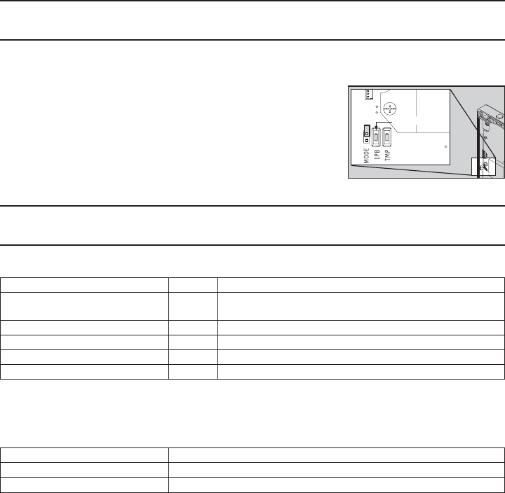
2. Login to the Schlage Utility Software (SUS) application.
3. The SUS will display “AD400” when communicating.
4. Select “Device Options”.
5. Select “PIM Properties”.
6. Select the “Edit” tab.
7. Select a new/different RF channel.
8. Save your selection.
9. Select the “Link” tab.
10. Select a “Door Address” and click on the “Link” button.
11. Disconnect the HHD from the PIM400 and try to link again using the new RF channel.
ENABLING DYNAMIC CHANNEL SWITCHING
! Enabling Dynamic Channel Switching will terminate links with other WAPMs previously
linked to the PIM400.
Dynamic Channel Switching (DCS) is controlled by the PIM400 the WPR400 is linked with. DCS may
be enabled on the PIM400 through the Schlage Utility Software (SUS).
Follow these steps to enable Dynamic Channel Switching on the WPR400.
1. Connect the HHD to the PIM400.
2. Login to the SUS application.
3. When communicating, the SUS will display “PIM400-485-RSI” for the PIM400-485, or
“PIM400-TD2” for the PIM400-TD2.
4. Select “Device Options”.
5. Select “PIM Properties”.
6. Scroll down to the “Dynamic Channel Switching” menu.
7. Select one of three (3) “Enable Channel”.
8. Save your selection.
9. Disconnect the HHD from the PIM400 and try to link again using the Dynamic Channel Switching
selection.
9
WPR-400 Wireless Portable Reader User Guide
RESETTING TO FACTORY DEFAULTS
! All information in the WPR400 will be deleted and reset to factory defaults!
1. Remove the WPR400 cover.
2. Press and hold Schlage button until two (2) beeps sound
(10 seconds).
3. Release the Schlage button.
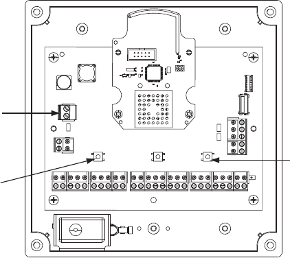
4. Press and release the Inside Push Button (IPB) three (3) times.
The top LEDs will fl ash when the reset is complete.
5. Replace the cover.
WPR400 LED REFERENCE
Link Mode LED Reference
Schlage LEDs Beeps Action
1 Red, 1 Green 0 One link request was sent to fi nd a PIM400 in link mode.
This action will repeat twice, then stop.
1 Green 0 Successful RF packet transmission
1 Red 0 Unsuccessful RF packet transmission
Z Green 1Z 2Linking was successful
3 Red 5 Linking was unsuccessful
1 Z = RF channel number on which the WPR400 is linked (1-10). The RF channel of each PIM400 in the area
should be known and recorded.
2 Number of beeps should match the RF channel number of the PIM400.
Normal Operation LED Reference
Schlage LEDs Action
Green A valid credential was presented to the WPR400 reader
Red An invalid credential was presented to the WPR400 reader
Inside Push Button
10
WPR-400 Wireless Portable Reader User Guide
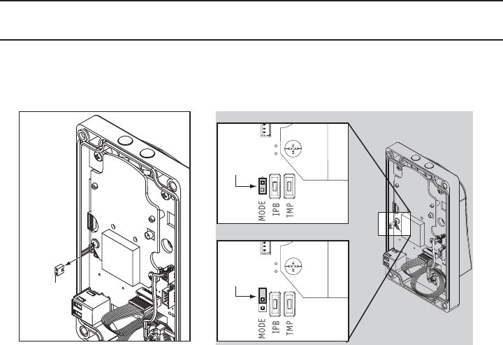
TEST MODE (NO CREDENTIAL READER REQUIRED)
! Disconnect the battery from the WPR400 while confi guring this mode. (See Steps 1 and 2
under Installing or Replacing Batteries on page 13.)
• Test mode is selected by opening the WPR400 and placing a jumper across the two pins of the
“Mode” connector located on the main circuit board.
Jumper
TESTER MODE
LINK MODE
Jumper
Jumper
Reassemble the WPR400 before powering on.
• When powered on, the WPR400 will automatically enter Test mode.
• If the link fails, the Schlage button will blink red three (3) times and fi ve (5) short beeps will sound.
The PIM400 will remain in link mode, so the link may be attempted again from the WPR400.
• To re-attempt WPR400 linking:
- Without a reader attached, cycle the WPR400 power switch.
- With a reader attached, present any credential OR press any number on the keypad.
11
WPR-400 Wireless Portable Reader User Guide
Linking to the PIM400-TD2 in Test Mode
1. Mount the PIM400-TD2 to the wall (or ceiling) in the exact location and in the same manner that
the PIM400-TD2 or PIM400-485 would be located and mounted (mounting hardware not included).
2. Remove the cover from the PIM400-TD2.
3. Connect the bare leads from the power supply to J2 (DC Power) screw terminal on the PIM400-TD2.
4. Connect the power supply to 120 VAC.
5. Press and release LINK 1 switch (SW2) to link Access Point 1, or LINK 2 (SW3) to link Access
Point 2. The corresponding LED (LED1 for LINK1; LED2 for LINK2) blinks red and green. This
indicates that the PIM400-TD2 is in Link Mode. To abort Link Mode, press the same switch again.
Link 2 Button
Link 1 Button
J2, DC Power
PIM400-TD2 Printed Circuit Board (PCB)

12
WPR-400 Wireless Portable Reader User Guide
Using the WPR400 in Test Mode
Do not attempt a pre-installation test if the WPR400 batteries
are low. See Batteries on page 13 for information on charging the
batteries.
Always locate the WPR400 in the intended mounting position(s)
before and during the linking process.
1. The WPR400 should be held in place at the exact spot where
the WAPM (WPR400, WRI400 or WSM400) will be installed.
(Always hold the WPR400 by the handle, not by the housing.)
2. Test on the intended door with the door open and with the
door closed.
3. Turn on the WPR400. It will perform a power-on test and then automatically enter Test mode. It
will then send 200 test packets to check the quality of the RF link. A successful link will produce
more green than red LED blinks during the link transmissions. See WPR400 Test Mode LED
Reference below for more information.
4. For each new link test, the WPR400’s power must be cycled off, then on.
WPR400 Test Mode LED Reference
In Test mode, the WPR400’s LEDs will blink to indicate RF communication quality as follows:
Schlage LEDs RF Communication Quality
Solid green, fast green blinks, or green with
very few red blinks
Good link
Solid red or fast red blinks Poor or no link
10 fast red blinks Low Battery, Test Incomplete (see Batteries on page 13)
A successful transmission rate greater than 85% is needed for a successful link and to ensure
that more than 99.6% of all RF transmissions will be completed error-free. If the RF transmission
is poor or unsuccessful, attempt modifi cations to improve the transmission. See Improving RF
Communications below.
Improving RF Communications
1. Ensure that the distance between the PIM400 and the WPR400 does not exceed 200 feet (61
meters). The PIM400 and the WPR400 should not be located on separate fl oors in a building.
2. If the linking problem still exists and the PIM400 is in a closet, move it outside the closet where a
Schlage Remote Antenna could be located. This will eliminate the RF attenuation from the closet
wall. If this allows linking, then the PIM400-TD2 or PIM400-485 should be mounted outside the
closet. If it is not desirable to mount the PIM400-TD2 or PIM400-485 outside the closet, then
mount it in the closet with the Schlage omnidirectional (remote) Antenna mounted outside the
closet.
3. If the linking problem still exists, use a PIM400-TD2 with a Schlage directional (remote) antenna
aimed at the non-linking WPR400 tester location.
4. Finally, move the PIM400 to another workable location nearer to the test site, then test again.
TIP
The fi rst time you test the link
to the PIM400-TD2 with the
WPR400 in Test mode, do so
within close proximity so that
you can observe a successful
link result before linking at a
remote distance.
13
WPR-400 Wireless Portable Reader User Guide
BATTERIES
Charging Batteries
Turn off the WPR400 before charging the battery.
1. Open the power jack cover.
2. Plug the battery charger in to the power jack.
3. Connect the battery charger to 120 VAC.
Full battery charge will take approximately 4-8 hours.
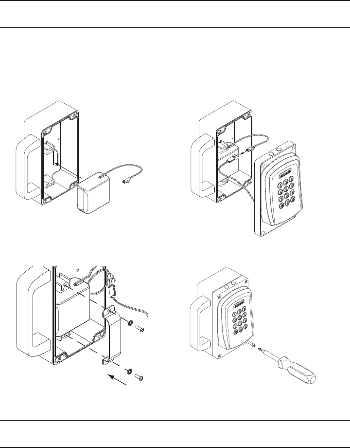
Installing or Replacing Batteries
1. Remove the WPR400 cover.
2. Disconnect the battery pack.
3. Remove the battery retainer and the old battery pack.
1.
2. 3.
14
WPR-400 Wireless Portable Reader User Guide
BATTERIES, Continued
4. Position the new battery pack in the same location as the old battery pack.
5. Connect the new battery pack.
6. Carefully pack the battery wires, and reattach the battery retainer.
7. Reattach the WPR400 cover making sure no wires are pinched.
4. 5.
6. 7.
TROUBLESHOOTING
For troubleshooting, browse to www.schlage.com/support.

15
WPR-400 Wireless Portable Reader User Guide
FCC/IC STATEMENTS
The communication module is a 900 MHz transceiver for electronic locks and non-lock devices. The communication
module links the access device to the Access Control Management System, with feedback control to the Access
Device via a wireless means. The module contains the embedded fi rmware implementing the radio physical and
data layers. The antenna associated with this module is a PCB trace inverted-L with a measured gain of 5.7 dBi.
Specifi cations of the radio module:
Power Output: 19.6 dBm
Operating Frequency: 906 -924 MHz
Modulation: BPSK
NOTE: The intended use of this module is not for the general public. It is generally for industry/commercial use only.
This transceiver is to be professionally installed in the end product by Ingersoll Rand, and not by a third party. The
Ingersoll Rand AD400 900 MHz Communication Board Module will not be sold to third parties via retail, general
public or mail order. In the case of a repair, the transceiver will be replaced by a professional Installer.
Federal Communication Commission Interference Statement
This equipment has been tested and found to comply with the limits for a Class B digital device, pursuant to Part
15 of the FCC Rules. These limits are designed to provide reasonable protection against harmful interference in a
residential installation. This equipment generates uses and can radiate radio frequency energy and, if not installed
and used in accordance with the instructions, may cause harmful interference to radio communication. However,
there is no guarantee that interference will not occur in a particular installation. If this equipment does cause harmful
interference to radio or television reception, which can be determined by turning the equipment off and on, the user
is encouraged to try to correct the interference by one of the following measures:
• Reorient or relocate the receiving antenna.
• Increase the separation between the equipment and receiver.
• Connect the equipment into an outlet on a circuit different from that to which the receiver is connected.
• Consult the dealer or an experienced radio/TV technician for help.
This device complies with Part 15 of the FCC Rules. Operation is subject to the following two conditions: (1) This
device may not cause harmful interference, and (2) this device must accept any interference received, including
interference that may cause undesired operation.
FCC/IC Caution
Any changes or modifi cations not expressly approved by the party responsible for compliance could void the user’s
authority to operate this equipment.
INDUSTRY CANADA STATEMENTS
Operation is subject to the following two conditions: (1) this device may not cause interference, and (2) this device
must accept any interference, including interference that may cause undesired operation of the device.

© 2010 Ingersoll-Rand Company
Printed in Country.
P516-098 Rev. 08/10-a