Schlage Lock LE LE Series Wireless Lock User Manual
Schlage Lock Company LE Series Wireless Lock Users Manual
Users Manual
*P518-027*
P518-027
Table of Contents
Prepare for Installation 2
Greenwich Trim Installation 3
Addison Trim Installation 6
User Guide 9
Customer Service
1-877-671-7011 www.allegion.com/us
Installation Preparation
Tools Needed
• Phillips screwdriver
• Lever installation tool
• Pliers
Optional
• Needle-nose pliers
• Drill with 3/8” drill bit
• T10 and T25 Torx drivers
Door preparation:
Contact Product Support at
1-877-671-7011.
IMPORTANT NOTES
Install and test lock with door open to avoid being locked out.
ENGAGE™ WEB & MOBILE APPLICATIONS
Search for “Allegion ENGAGE” in the Apple App Store or Google
Play store to download the app.
Navigate to portal.allegionengage.com to access your account
online
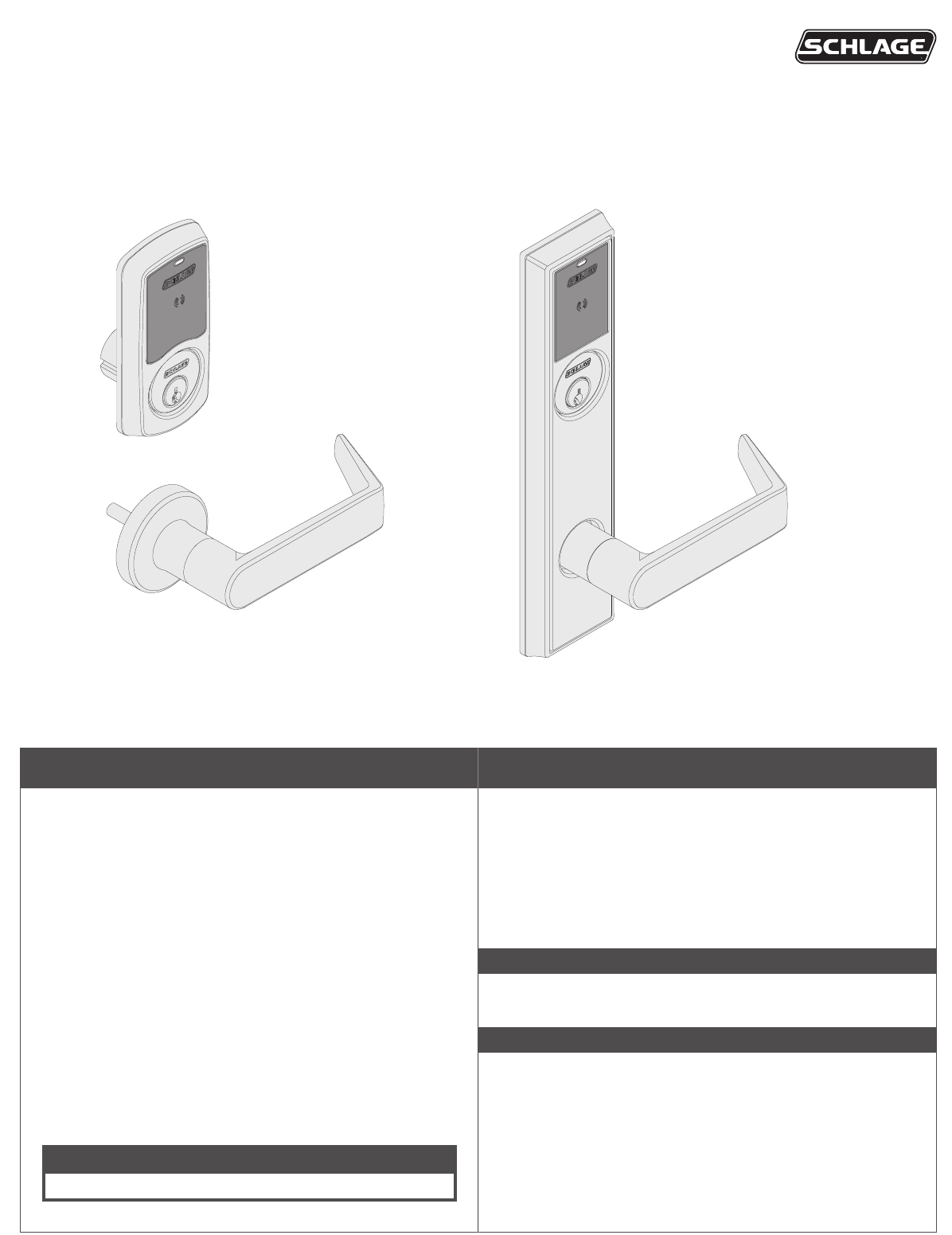
LE-Lock - PILOT ONLY
Model LE Installation Instructions and User Guide
Sectional Trim
Greenwich (GRW)
Escutcheon Trim
Addison (ADD)
2
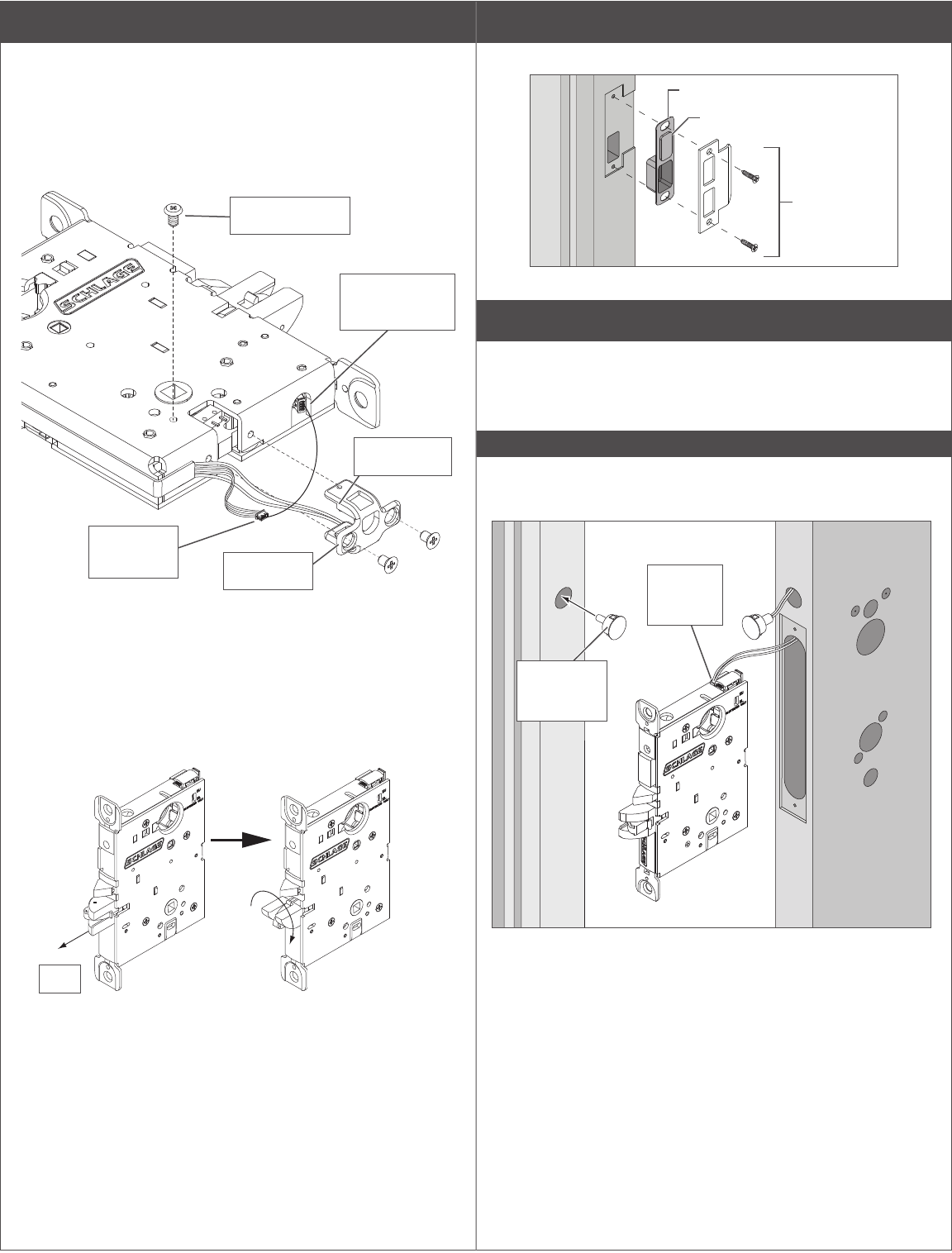
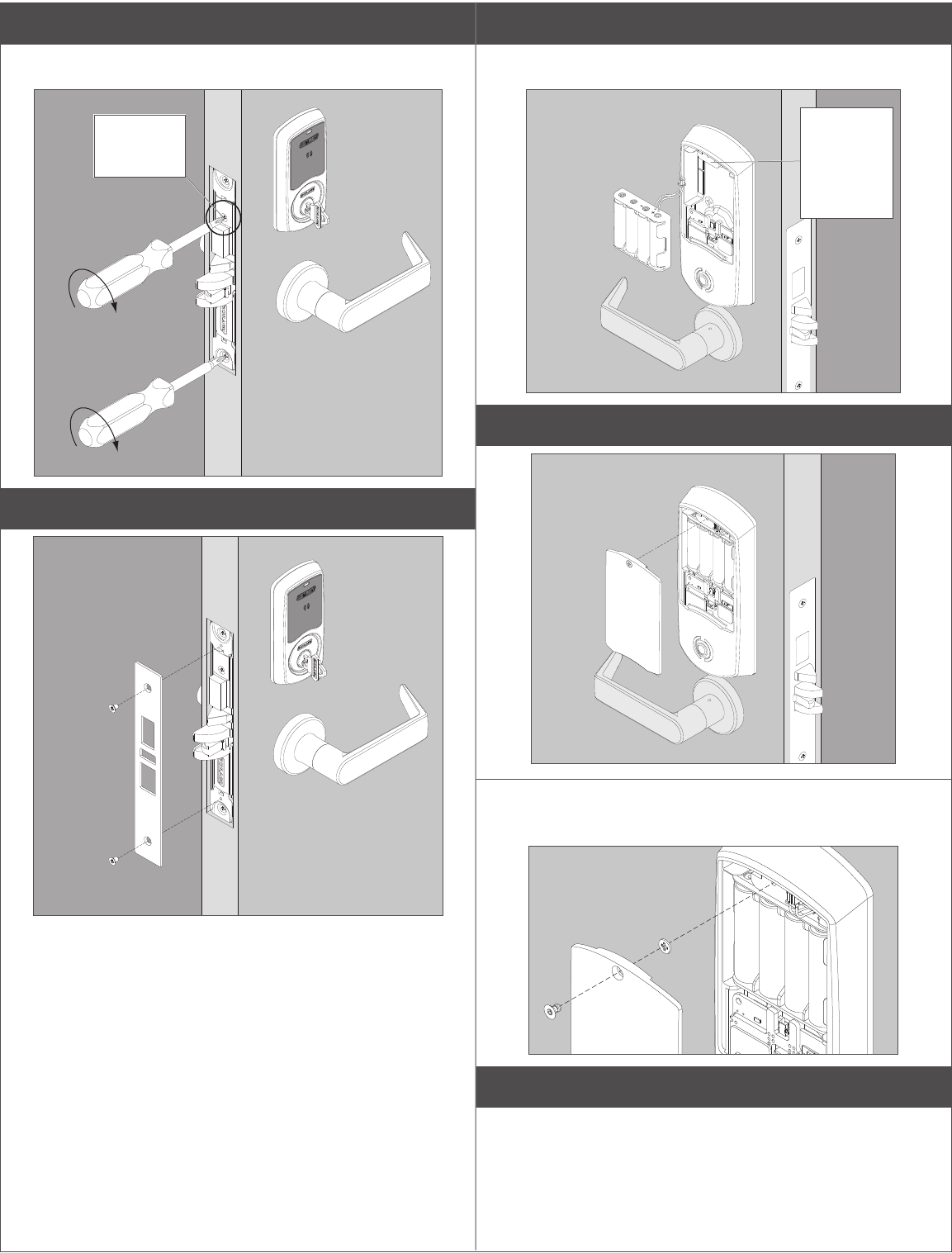
A Adjust door handing.
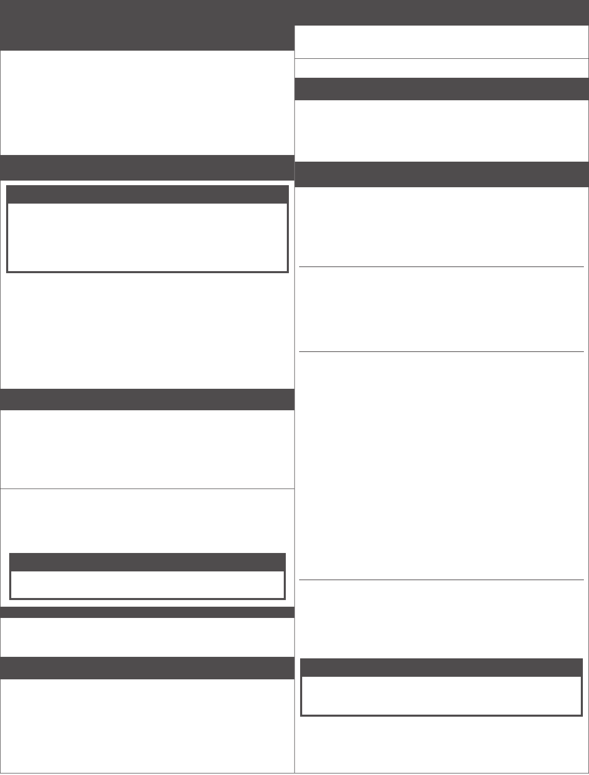
RX (request to exit) utilizes a microswitch inside the lock case to detect
rotation of the inside knob/lever. The switch then signals the use of the
opening to the security system.
The RX is a removable module located on the bottom edge of the lock
chassis. The module must be properly positioned to detect inside knob/
lever rotation. If not properly positioned, the lock and/or microswitch may
be damaged.
Handing screw
Microswitch
Connect 4-pin
connector here
RX module
Lower 4-pin
connector
Change lock handing with RX
Disconnect lower 4-pin connector and rotate it out of the way of the RX
module.
LIMPORTANT: Move handing screw to inside of door.
1. Remove the RX module.
2. Remove the handing screw.
3. Rotate the latch 180° (if necessary).
180˚
Pull
4. Reinstall the handing screw onto the inside of door.
5. Reinstall the RX module with the microswitch on the inside of the
door (the same as the handing screw).
6. Reconnect the lower 4-pin connector after the RX module is
reinstalled.
B Install strike.
FOR DEADBOLT ONLY: Strike box will not have a DPS magnet.
DPS strike box
Strike
(10-136 shown)
Magnet (for non-deadbolt
models only)
C Deadbolt Only: Install door position switch and magnet.
Feed the wires from the connector on the door position switch into the
long angled hole in the door. Plug the connector into the chassis. Do not
push in switch all the way, leave a little slack until the chassis is installed
after step 1.
IMPORTANT:
Make sure the door position magnet in the door jamb is aligned with
the door position switch in the door edge!
Connect
cable to
chassis
Insert
magnet into
door jamb
3
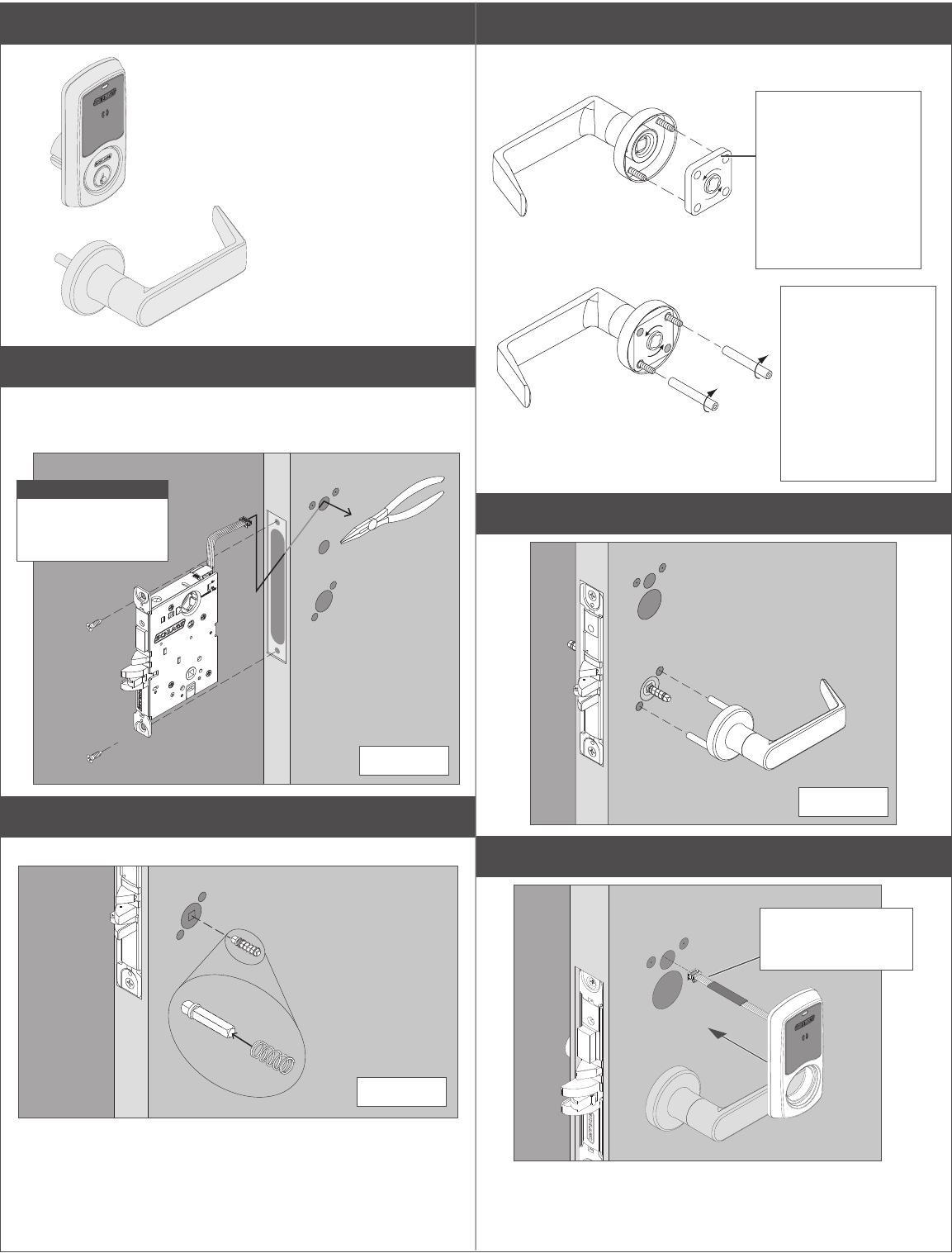
Installation Instructions for Sectional Trim
Continue for installation
instructions for your lock with
Greenwich (sectional) trim.
For Addison (escutcheon) trim
instructions go to page 6.
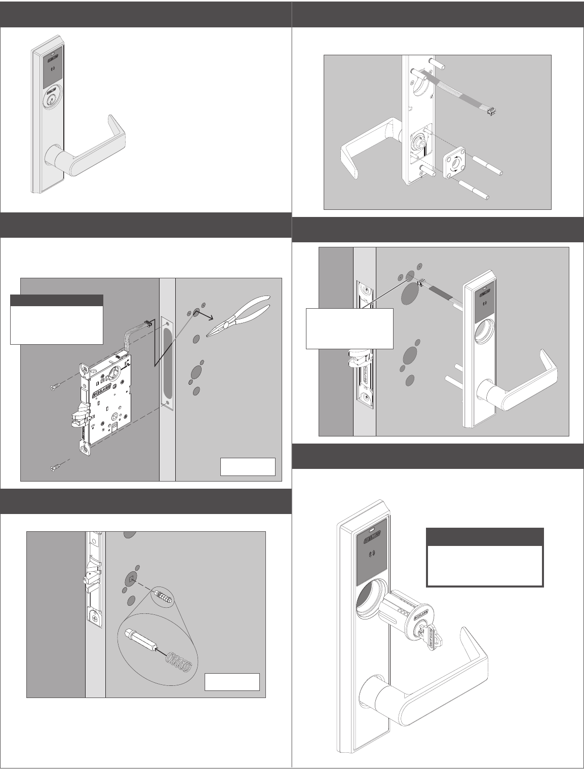
1 Install chassis.
Route chassis connector through the upper 5/8” hole on the interior side
of the door, and pull through the slack as you slide chassis into mortise.
You may use needle-nose pliers to gently pull the cable through the hole.
CAUTION
Start screws but
don’t fully tighten
until Step 11!
INTERIOR
2 Install lever spindle on the exterior side of the door.
Install spring on lever spindle.
EXTERIOR
3 Install spring cage into lever.
Use pliers carefully to install mounting posts to avoid damage.
Fully tighten mounting
posts on screws
Apretarlos
completamente los
puntales de montaje
en tornillos
Serrer à fond les
tenons de montage
sur les vis
Arrow in direction of
lever down rotation
Flecha en dirección del
giro descendente de la
manija
Flèche dans le sens de
la rotation vers le bas
de la poignée
4 Install outside lever.
EXTERIOR
5 Install the outside trim and route wire through.
Route wire all the
way through hole to
interior side of door.
4
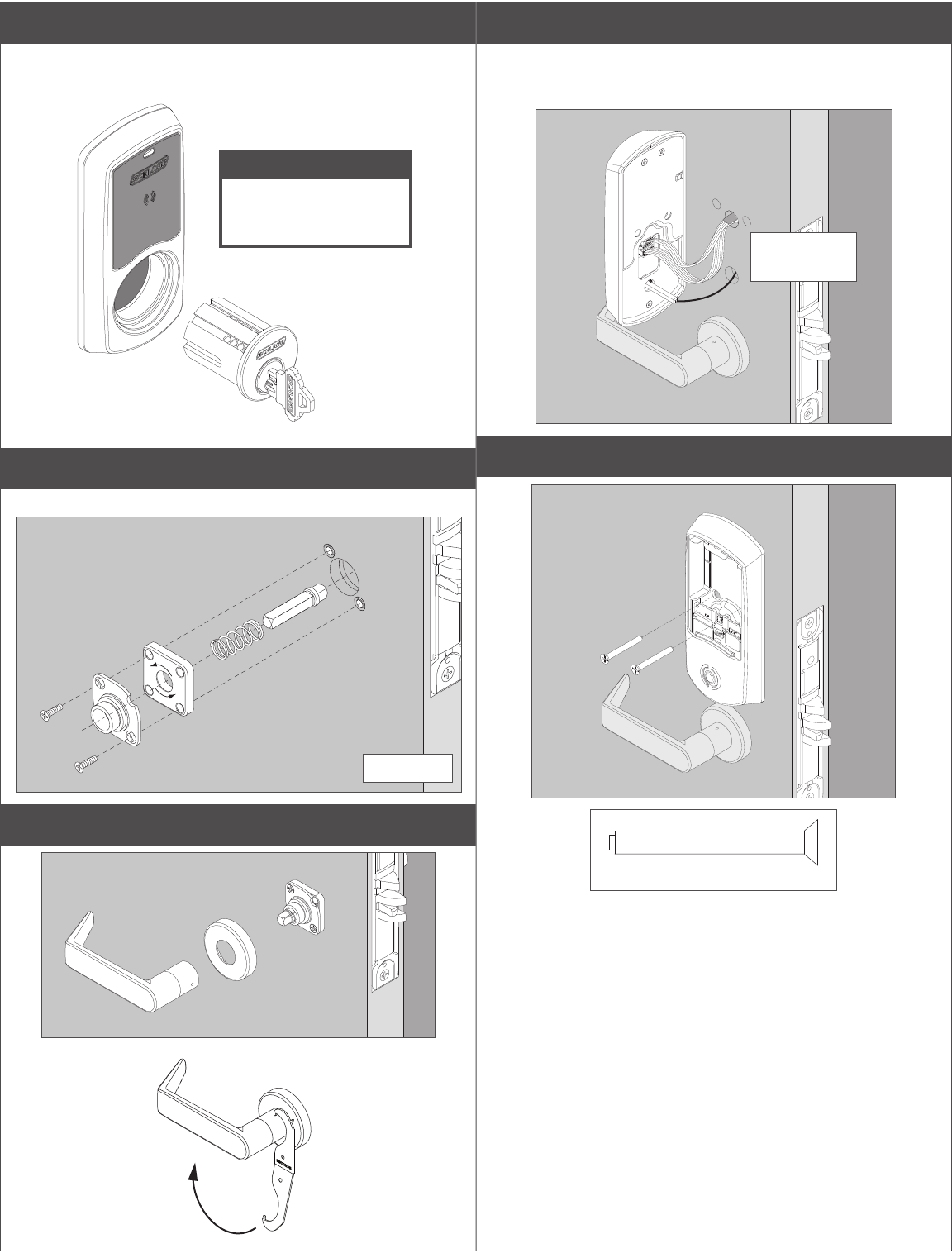
6 Partly install the key cylinder.
Turn key cylinder six (6) full turns into the chassis. Insert key in cylinder
to aid with turning, but pull key out one notch.
CAUTION
Do not tighten more than
six full turns! Tighten
fully at step 11!
7 Install spindle, spring cage, and mounting plate
Arrow on the mounting plate faces in direction of lever down rotation.
INTERIOR
8 Install the rose and inside lever
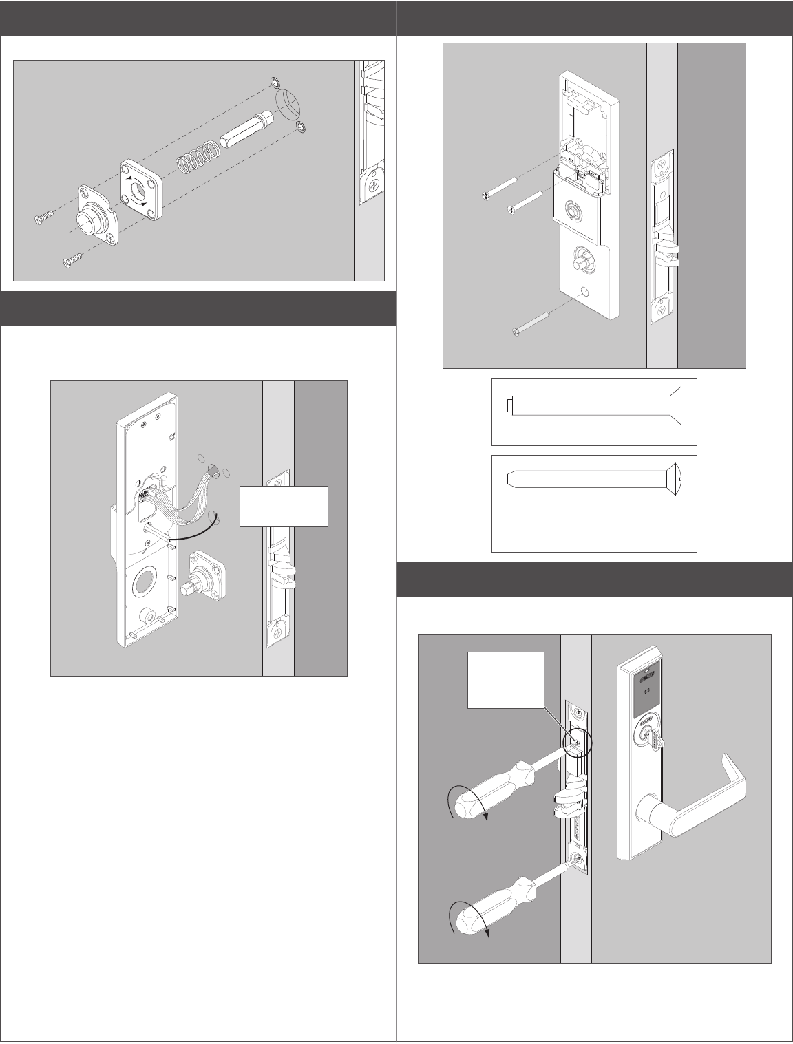
9 Connect the cables to the inside assembly
There are two cables that need to be connected.
FOR DEADBOLT ONLY: Align driver bar into the chassis. Thumbturn
should be vertical.
Cables droop
downward.
10 Install the inside assembly.
Actual Size
5
11 Fully tighten the key cylinder and chassis screws.
The cylinder face needs to be ush to the outside escutcheon. Tighten
the cylinder mounting screw.
Cylinder
mounting
screw
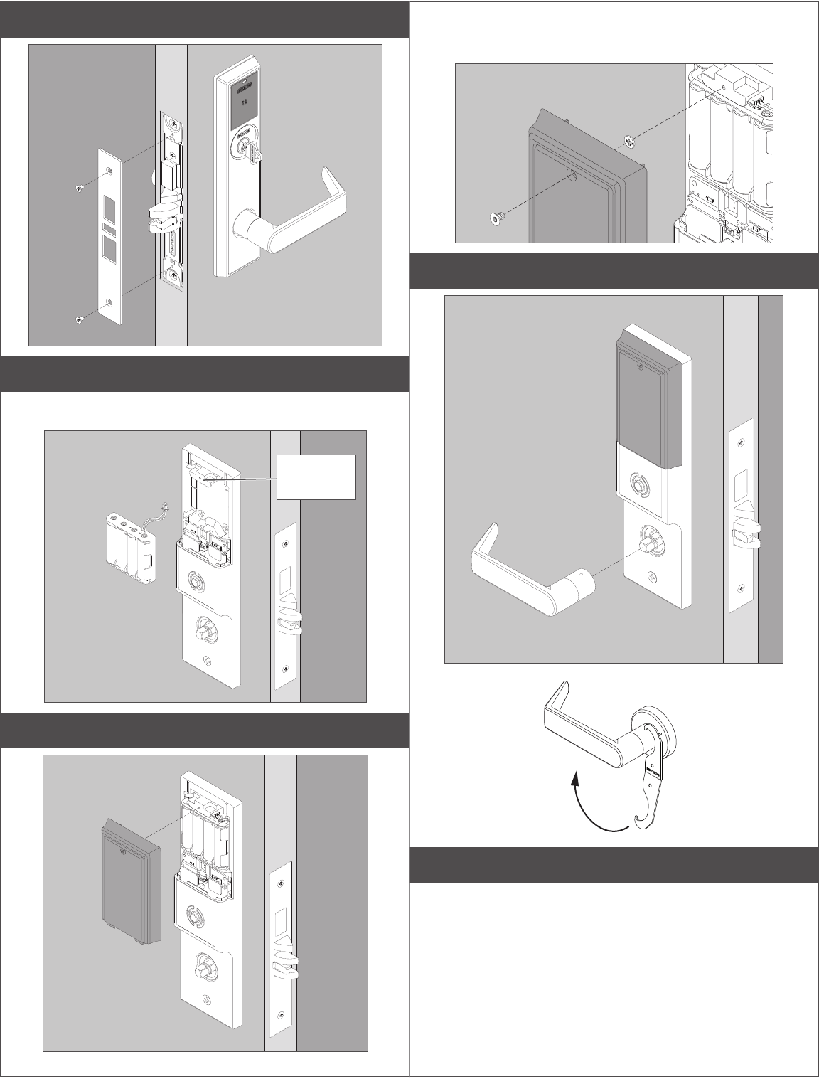
12 Install the armor plate.
13 Connect the battery cable.
Install four (4) AA batteries into the battery holder. Tuck the cable behind
the tab in the escutcheon
Tuck cable
behind tab
after battery
holder
installation.
14 Install the battery cover and tighten the screw.
14a Optional: Install security screw and washer.
Remove standard screw and washer and replace with security screw
and washer.
15 Continue to User Guide.
Go to page 9 for information for programming your lock.
6
Installation Instructions for Escutcheon Trim
Continue for installation
instructions for your lock with
Addison (escutcheon) trim.
For Greenwich (sectional) trim
instructions go to page 3.
1 Install chassis.
Route chassis connector through the upper 5/8” hole on the interior side
of the door, and pull through the slack as you slide chassis into mortise.
You may use needle-nose pliers to gently pull the cable through the hole.
CAUTION
Start screws but
don’t fully tighten
until Step 9!
INTERIOR
2 Install lever spindle on the exterior side of the door.
Install spring on lever spindle.
EXTERIOR
3 Install mounting posts and spring cage.
Arrow on the spring cage points in direction of lever down rotation. Use
pliers to carefully install mounting posts to avoid damage.
4 Install the outside trim.
Route wire all the
way through hole to
interior side of door.
5 Partly install the key cylinder.
Turn key cylinder six (6) full turns into the chassis. Insert key in cylinder
to aid with turning, but pull key out one notch.
CAUTION
Do not tighten more than
six full turns! Tighten
fully at step 9!
7
6 Install spindle, spring cage, and mounting plate.
Arrow on the spring cage point in direction of lever down rotation.
7 Connect the cables to the inside assembly
There are two cables that need to be connected.
For deadbolt only: align driver bar into the chassis. Thumbturn must be
vertical.
Cables droop
downward.
8 Install the inside assembly.
Actual Size (2 mounting screws)
Actual Size (bottom screw)
Phillips or T-25 security screw
Finished to match escutcheon
9 Fully tighten the key cylinder and chassis screws.
The cylinder face needs to be ush to the outside escutcheon. Tighten
the cylinder mounting screw.
Cylinder
mounting
screw
8
10 Install the armor plate.
11 Connect the battery cable.
Install four (4) AA batteries into the battery holder. Tuck the cable behind
the tab in the escutcheon
Tuck cable
behind tab.
12 Install the battery cover and tighten the screw.
12a Optional: Install security screw and washer.
Remove standard screw and washer and replace with security screw
and washer.
13 Install the inside lever.
14 Continue to User Guide.
Go to page 9 for information for programming your lock.
9
Lock Testing
Power On Self Test
The Power On Self-Test (POST) is a self-diagnostic test that the
lock runs to verify that the lock is installed correctly. The POST takes
approximately 30 seconds. During the POST, a series of audible beeps
and LED ashes will occur. If the POST detects an issue, the test will
conclude with three red ashes of the outside LED. Once commissioned
with the ENGAGE mobile application, any issues identied during POST
can be viewed under the View Activity menu.
Standalone/Construction Access Mode
CAUTION
Standalone/Construction Access Mode is NOT required to
operate the lock!
Skip this section and proceed to “Getting Started with the ENGAGE™
Mobile Application” to commission the lock and begin using the
ENGAGE cloud-based web and mobile applications to congure lock
settings, manage user access, and view audits and alerts.
Standalone/Construction Access Mode requires an electronic credential.
• Enabled by default and after a Factory Default Reset (FDR).
• The lock will remain in Standalone/Construction Access Mode until
the mode is cancelled as described below.
• No audits are captured while the lock is in Standalone/
Construction Access Mode.
LOnce enabled, Standalone/Construction Access Mode requires a
factory default reset to exit this mode and allow commissioning
with the ENGAGE mobile application.
1 Create the Master Programming Credential.
The rst card presented to a new lock while turning the inside lever
automatically becomes the Master Programming Credential. The Master
Programming Credential will not grant access. It is used only to add
additional credentials.
LUse the same Master Programming Credential for all the locks
in the facility.
1a Turn and hold down the inside lever and present to the LE
reader the card you want to make the Master Programming
Credential.
The LE LED will blink ve times for successful enrollment of Master
Programming Credential.
CAUTION
Do NOT lose the Master Programming Credential.
If lost, reset the lock to factory settings.
WARNING
If the rst card presented to a new lock to create the Master
Programming Credential is not accepted, the lock has either been
programmed or already has a Master Programming Credential.
2 Enroll user construction credentials.
2a Present the Master Programming Credential.
The LE LED will shine steady for twenty seconds. If no credentials are
presented during this time, the lock will leave construction enrollment
mode and return to Standalone/Construction Access Mode.
2b Present credential to enroll for access.
The LED will blink green ve times and beep if successful.
2c To enroll more credentials, repeat steps 2a and 2b.
3 Remove user construction credentials.
The only way to remove credentials from Standalone/Construction
Access Mode is to perform a Factory Default Reset (FDR) on the lock
and re-enter Standalone/Construction Access Mode by creating a new
Master Programming Credential and re-enrolling the other credentials.
Getting Started with the ENGAGE™ Mobile Application
ENGAGE cloud-based web and mobile applications make it easy to
congure lock settings, manage user access and view audits and alerts
from anywhere.
Your new LE wireless lock can be connected to your Wi-Fi network to
receive updates automatically overnight or can be updated anytime from
the ENGAGE mobile application when within Bluetooth range.
Download the ENGAGE mobile application
Search for “Allegion ENGAGE” on the App Store (iOS) or Google Play
Store (Android) to download the free ENGAGE mobile application.
The ENGAGE app is compatible with iPhone 4S and newer models
running iOS 9 or newer. Android devices require Android Kitkat 4.4 or
newer.
Register a new ENGAGE account
An account is required to use the ENGAGE cloud-based web and mobile
tools.
Register for an ENGAGE account in the mobile app by selecting the
“Create an Account” button from the sign in screen. You can also register
for a new account on the web at https://portal.allegionengage.com/
signup
New account registration requires a valid email address, secure
password, First and Last Name, and Site Name (for example, the
business name where the locks will reside).
Note that the password must be at least 10 characters in length and
contain three of the following: lower case letters (a-z), uppercase letters
(A-Z), numbers (0-9) and special characters (e.g., !@#$%^&*). No more
than two identical characters in a row can be used.
Select “Register” (in the mobile app) or “Sign-Up” (on the web) upon
completing all of the required information. After registering for a new
account, you will receive a verication email. You must click on the link
in the message to verify your account. This is required to keep your
account active.
Commission a lock
To manage your LE lock with the ENGAGE cloud-based web and mobile
applications, it must be commissioned with the ENGAGE app.
LBefore commissioning, the lock must be fully assembled with the
batteries installed and the battery connector plugged in. The battery
cover MUST be installed.
CAUTION
If the lock has been put into Standalone/Construction Access
Mode, a Factory Default Reset (FDR) will need to be performed
(see Factory Default Reset).
1. Sign in to the ENGAGE mobile app.
2. iOS: Select “Connect from the tab bar at the bottom of the screen.
Android: Select “Connect to Locks” from the menu.
User Guide

10
3. Select the “+” icon in the upper right corner.
4. Follow the lock commissioning wizard to complete initial setup of
the lock.
Locks can be commissioned as new, from a previously created prole,
or cloned from an existing lock in your site. Upon selecting from these
options (described below), the LED on the outside of the lock will begin
blinking red to indicate connectivity with the app.
• Select “Add New” to commission the lock with new conguration
and access rights. This is the most common scenario when
commissioning a lock.
• Select a lock from the clone list to give the lock the same
conguration and access rights as another lock you’ve already
commissioned on your site.
If you’re unsure which option to choose, select “Add New.”
Congure Wi-Fi
Your LE wireless lock can be connected to a Wi-Fi network to receive
updates from the ENGAGE cloud automatically, overnight.
Prior to conguring the Wi-Fi connection settings for your lock, consider
contacting your network administrator to obtain the SSID, security type,
password, and in some higher security congurations, the user ID.
Wi-Fi conguration can be set in the lock during the commissioning
process or any time while connected to the lock from the “Connect” (iOS)
or “Connect to Locks” (Android) menu.
1. Connect to the lock.
The lock must be within approximately 50 feet of your mobile
device.
2. Select “Wi-Fi.”
3. From the Wi-Fi menu, toggle Wi-Fi on.
a. Enter Wi-Fi SSID.
b. Choose the correct security protocol.
c. Enter the username (for WPA-Enterprise security only).
d. Enter the password.
e. Select “Finish” or “Save.”
LFor applications using WPA-Enterprise (PEAP) security protocol, a
unique user name and password (common across all LE locks) is
recommended.
Upon completing Wi-Fi set-up, the lock will turn on its Wi-Fi and attempt to
connect to the network, indicated by a ashing amber LED on the reader.
LDo not attempt to guess Wi-Fi conguration details. Prior to
conguring the Wi-Fi connection settings for your lock, conrm
conguration details with your network administrator.
Add a user (credential holder) to the cloud database and
enroll a credential
The rst step in granting access rights for a user to a lock is to create
a prole and enroll a credential for them in the ENGAGE cloud database.
1. iOS: Select “Users” from the tab bar at the bottom of the screen.
Android: Select “Manage Users” from the menu.
2. Select the “+” icon in the upper right corner.
3. Enter the new user’s rst name and last name.
4. Select “Credentials” from the menu.
5. Select the “+” icon in the upper right corner.
6. Select the device you want to use to enroll the credential (any
commissioned LE lock can be used as an enrollment reader).
7. When the Credentials detail screen displays, present the credential
to the reader. (You will have 10 seconds to present the credential).
The mobile app will show that the credential was received, and it
will be given a name based on the order it was added to the user
record (for example: Credential 1, Credential 2, etc.).
8. Select the Credential Type (the default is “Normal”).
• Normal: Unlocks the lock momentarily (with a specied relock
delay period).
• Toggle: Changes the state of the lock from locked to unlocked, or
vice versa.
• Freeze: Freezes the lock in the current state. Lock remains frozen
until Freeze credential is presented again. Disables all other
credentials except for Pass Through.
• Pass Through: Unlocks a lock momentarily, regardless of state.
Overrides a lock in Freeze and Lock Down states.
• Lock Down: Changes the state of the lock to locked and disables
all credentials except for Pass Through and Freeze. Present a
Freeze to return lock to normal state.
• One Time Use: Allows only one Normal access per assigned lock.
• Block: Denies access to the lock and records the access attempt
as an audit.
9. Select “Save”.
Upon successfully completing these steps, a new user will be created
with a credential enrolled to them in the ENGAGE cloud database.
The new user does NOT yet have access to any locks.
Grant a user access rights to locks in the cloud database
The next step in granting access rights for a user to a lock is to assign
access rights to locks in the ENGAGE cloud database.
1. iOS: Select “Users” from the tab bar at the bottom of the screen.
Android: Select: “Manage Users” from the menu.
2. Select the desired user.
3. Under “Manage Access,” select “Locks.”
4. Select the locks you wish to assign the user access to.
Selected locks will have a check mark.
5. Select “Save” or “Done.”
Upon successfully completing these steps, a user will be granted access
rights to locks in the ENGAGE cloud database. The lock must be
updated for the change to take eect.
Send updates to user access rights to the lock
If the lock has been congured to connect to a Wi-Fi network, it will
automatically update overnight.
If the lock has not been congured to connect to a Wi-Fi network, or if
the update is urgent, connect to the lock with the ENGAGE app to send
the update.
Bluetooth must be enabled on your device and you must be within
approximately 50 feet of the lock to connect.
1. iOS: Select “Connect” from the tab bar at the bottom of the screen.
Android: Select “Connect to Locks” from the menu.
2. Select the desired lock.
3. Select “Update Door File.”
Upon successfully completing these steps, the lock will be updated with
the latest user access rights and the audit history will be uploaded to the
ENGAGE cloud database.
11
View lock audit information
Audit information for each lock can be viewed from anywhere with the
ENGAGE mobile app.
Audit information is stored and viewed from the ENGAGE cloud
database. If the lock has been congured to connect to the Wi-Fi
network, audit information will be uploaded to the ENGAGE cloud
database daily. If the lock has not been congured to connect to a Wi-Fi
network, you must rst connect to the lock with the ENGAGE mobile app
and select “Update Door File” or “Get Audits.”
1. iOS: Select “Devices” from the tab bar at the bottom of the screen.
Android: Select “Manage Devices” from the menu.
2. Select the desired lock.
3. Under “Device Audits,” select “Display Activity.”
LTo see basic information related to access history, use the Activity
view. To view the results of the built in diagnostic test or for
troubleshooting related to Wi-Fi connectivity or other issues, use the
Diagnostics view.
Invite others to assist with administrative duties for
your site
1. iOS: Select “My Team” from the tab bar.
Android: Select “My Team” from the menu.
2. Select the “+” icon in the upper right corner.
3. Enter the email address, rst name, last name and role of the
person you wish to invite.
• Administrator: The most trusted administrative access role. The
Administrator can perform all duties within the ENGAGE web and
mobile applications.
• Manager: Same administrative privileges as an Administrator but
cannot invite or remove other Managers or Administrators.
• Operator: The most limited access. An operator can only connect
to locks to send updates or perform diagnostics.
4. Select “Save.”
Factory Default Reset (FDR)
A Factory Default Reset (FDR) will return the LE lock settings to the
original settings as shipped from the factory. Removes congurations,
databases, and requires the lock to be re-captured. A FDR will not
remove the lock from your ENGAGE account.
A Press and hold the FDR button for ve seconds.
The LE will blink green two times and beep two times.
B Turn the inside lever three times within 20 seconds.
LED will blink red and lock will beep with each turn.
C Reinstall battery cover, then use the app to capture
your lock.
Turn the inside lever. The LE will communicate on BLE looking for your
mobile device for two minutes after each lever turn in FDR mode.
If you have used this LE in Construction Access Mode, you must
complete a FDR before it will communicate on BLE.
Safe Mode
CAUTION
Enter Safe Mode only as a last resort! Entering Safe Mode
causes the lock to load a special version of rmware
intended to be immediately updated. Once in safe mode,
commission the lock with the ENGAGE mobile application
and perform a rmware update.
To put the lock in Safe Mode:
1. Remove power from the lock.
2. Turn the inside lever 2 times.
3. Apply power to the lock.
4. When the inside LED begins to blink, turn and hold the inside lever.
5. Press the FDR button 3 times to begin Safe Mode process.
The lock will not perform the Safe Mode process if the above
sequence is not completed within 10 seconds.
Lock Indicator Guide
Indicators Meaning
Fast ash green x5 Construction Access Mode:
Successful creation of master or
user construction credential.
Steady green until
timeout (20 seconds)
Construction Access Mode: Waiting
for credential after presentation of
master construction credential.
Long ash red x2 Manual/Construction Mode: Timed
out to construction mode.
Flash red x9 followed
by the respective
credentials indication
Low battery.
Flash green x1 +
beep, then ash red
x1 upon relock
Access granted.
Flash green x2 +
beep
Already unlocked.
Flash red x12 + beep In secure privacy/lockdown mode.
Flash red x1 + beep Access denied
Flash alternate green-
red x5 + beep
Freeze/Lockdown mode.
Flash red x4 + beep Access denied. Outside credential
schedule.
Flash red x1 per
second
BLE communicating.
Fast ash green x3 +
fast beep x3
Power On self test - Pass.
Fast ash red x3 Power O self test - Fail.

© Allegion 2016
Printed in U.S.A.
P518-027 Rev. 08/16-a
FCC Statement
This equipment has been tested and found to comply with the limits for a Class B digital
device, pursuant to Part 15 of the FCC Rules. These limits are designed to provide
reasonable protection against harmful interference in a residential installation. This
equipment generates, uses, and can radiate radio frequency energy and, if not installed
and used in accordance with the instructions, may cause harmful interference to radio
communication. However, there is no guarantee that interference will not occur in a
particular installation. If this equipment does cause harmful interference to radio or
television reception, which can be determined by turning the equipment o and on, the
user is encouraged to try to correct the interference by one of the following measures:
Reorient or relocate the receiving antenna.
Increase the separation between the equipment and receiver.
Connect the equipment into an outlet on a circuit dierent from that to
which the receiver is connected.
Consult the dealer or an experienced radio/TV technician for help.
FCC Caution: Any changes or modications not expressly approved by the party
responsible for compliance could void the user’s authority to operate this equipment.
This device complies with Part 15 of the FCC Rules. Operation is subject to the following
two conditions: (1) This device may not cause harmful interference, and (2) this device
must accept any interference received, including interference that may cause undesired
operation.
FCC Radiation Exposure Statement
To comply with FCC/IC RF exposure requirements for mobile transmitting devices, this
transmitter should only be used or installed at locations where there is at least 20 cm
separation distance between the antenna and all persons.
Industry Canada Statement
Under Industry Canada regulations, this radio transmitter may only operate using an
antenna of a type and maximum (or lesser) gain approved for the transmitter by Industry
Canada. To reduce potential radio interference to other users, the antenna type and its
gain should be so chosen that the equivalent isotropically radiated power (e.i.r.p.) is not
more than that permitted for successful communication.
Industrie Canada Déclaration
Conformément à la réglementation d’Industrie Canada, le présent émetteur radio peut
fonctionner avec une antenne d’un type et d’un gain maximal (ou inférieur) approuvé
pour l’émetteur par Industrie Canada. Dans le but de réduire les risques de brouillage
radioélectrique à l’intention des autres utilisateurs, il faut choisir le type d’antenne et son
gain de sorte que la puissance isotrope rayonnée équivalente (p.i.r.e.) ne dépasse pas
l’intensité nécessaire à l’établissement d’une communication satisfaisante.
Industry Canada Radiation Exposure Statement
This Device complies with Industry Canada License-exempt RSS standard(s). Operation
is subject to the following two conditions: (1) this device may not cause interference,
and (2) this device must accept any interference, including interference that may cause
undesired operation of the device.
Industrie Canada l’exposition aux radiations
Le présent appareil est conforme aux CNR d’Industrie Canada applicables aux appareils
radio exempts de licence. L’exploitation est autorisée aux deux conditions
suivantes : (1) l’appareil ne doit pas produire de brouillage, et (2) l’appareil doit
accepter tout brouillage radioélectrique subi, même si le brouillage est susceptible d’en
compromettre le fonctionnement.
UL Statements
• Outside lever is normally locked. Inside lever always allows egress.
• Unit shall not interfere with the operation of Panic Hardware.
• Wireless communications, Wi-Fi, Bluetooth, Door Position, and Request to
Exit switch features are not part of UL Listed product.
• Tested to compliance with UL 294 5th Edition Class I.
Customer Service
1-877-671-7011 www.allegion.com/us
Additional Notes: Revision History Revision Description:
A > English-only Pilot Revision; DO NOT PRINT FOR RELEASE
A B C D E F
070328
Material
White Paper
Edited By Approved By EC Number Release
Date
R. Byun P. Bockelman 070328 10-19-2016
Notes
1. printed two sides
2. printed black
3. tolerance ± .13
4. printed in country may vary
5. drawings not to scale
6. 12 page saddle-stitched booklet
Title
LE-Lock IS/UG
Creation Date
08-24-2016
Number
P518-027
Revision
A
Created By
R. Byun Activity
3899 Hancock Expwy
Security, CO 80911 © Allegion 2016
Software: InDesign
CS6
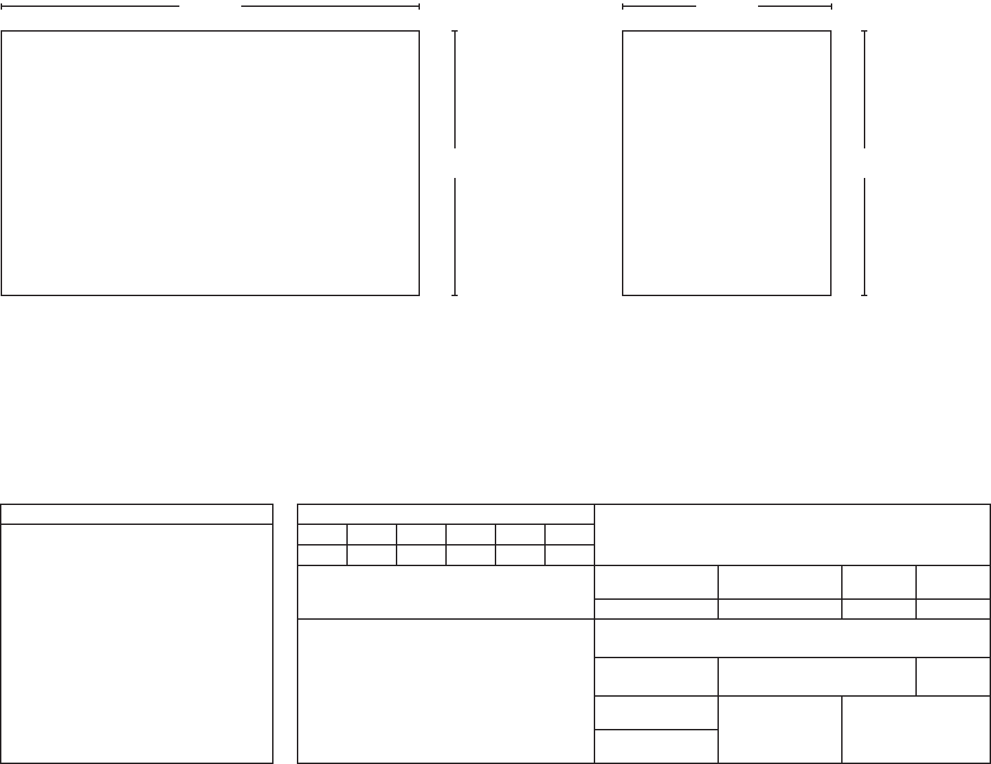
FLAT SHEET FINAL BOOKLET SIZE
8.500
11.000
FRONT
17.000
11.000
FRONT