Schlumberger Sema CBAMM Utility Meter Transmitter User Manual Revise manual
Schlumberger Sema Utility Meter Transmitter Revise manual
Users Manual Revised 041902
MPI: GE, 240v, single phase, Meter Remanufacturing Process
97-xxxx, Rev :G
Title: MPI: GE, 240V,Single Phase, Remanufacturing Instructions (for Third Party)
Doc. Number: 97-xxxx Revision: A Page: 1 through 13
Process Owner: Process Development Engineering
Revision History
ECO/ECN
Rev
Date
Author
Pages
Description of change
A 12/19/01 M.Qua 14 Initial Release

MPI: GE, 240v, Single Phase, Remanufacturing Process
97-xxxx, Rev:A Page 2 of 13
Table of Contents:
1. Purpose
2. Required Tooling
3. Inspection
4. 240v Module Disassembly
5. 240v AC Cable Disconnection
6. Interrupter Disassembly
7. Power Cable Installation
8. Interrupter Instalation
9. BAMM Installation
10. 120v Additional Parts and Tooling Requirements
11. 120v Specific BAMM Installation
12. 120v Specific AC Cable Connection

MPI: GE, 240v, Single Phase, Remanufacturing Process
97-xxxx, Rev:A Page 3 of 13
1. Purpose
This procedure details the disassembly of 240V modules and the retrofitting of the single
phase, 240V BAMM(40-1716), 240 V BAMMCCSK (40-0318), and 120 VBAMM onto a GE I70-
S meters.
2. Tools and Materials Required
NOTE: A grounded wriststrap must be worn during assembly.
The following tools and materials are required for meter retrofit:
CellNet Part No. Description Used On Quantity
40-1716 GE 240V Single Phase BAMM 240VBAMM 1
40-1719 GE 120V Single phase BAMM
40-0318 GE 240V Single Phase BAMMCCSK BAMMCCSK 1
n/a GE I70 Meter all 1
29-1126 GE interrupter (labeled w/”G”)all 1
17-1188 GE interrupter installation tool (Spacer=0.225”,NEW) 240V BAMM/ 1
BAMMCCSK
19-0035 240V BAMM AC cable( new spring clip) 240VBAMM/ 2
BAMMCCSK
22-0557 GE housing mounting screws all 2
n/a Needlenose pliers all 1
n/a Phillips #1 screwdriver (electric) all 1
n/a Phillips #1 screwdriver (manual) all 1
Other tools that may be required to remove the
nameplate, depending on the age of the meter:
- Phillips #2 screwdriver (manual) all 1
- Chisel blade screwdriver, 1/4”all 1
- Spintight 1/4” nutdriver all 1
n/a Orange stick (or equivalent) all 1
n/a New AC wire installation tool (I70 S-I, I70 S-II) 240V BAMM/ 1
BAMMCCSK
MPI: GE, 240v, Single Phase, Remanufacturing Process
97-xxxx, Rev:A Page 4 of 13
DISASSEMBLY INSTRUCTIONS
3. Inspection (refer to 96-0072, Retrofit Meter Quality Acceptance Criteria)
3.1 Inspect the meter and cover for the following:
- Meter and cover cleanliness, and no moisture inside the meter base
- Unacceptable base damage
- Lightning arrestors are in place and undamaged
- Filters are in place
- Cover seal (gasket) is in place
- Insure that the meter is not unidirectional
-Verify that the hi-pot barrier is in position
3.2 Verify that the AEP code on the label matches the meter type:
3.3 Module Inspection: Make sure the green PCB board is securely screwed into the
BAMM/BAMMCCSK enclosure. There should be no visible gap between the top edge of the
PCB and the top edge of the plastic enclosure.
4. Module Disassembly
4.1 Carefully remove glass cover from meter.
4.2 Remove screws from module using a Philips #2 Screwdriver. Always use a manual
screwdriver when unscrewing the module from the meter in order to prevent debris from
falling into the meter.
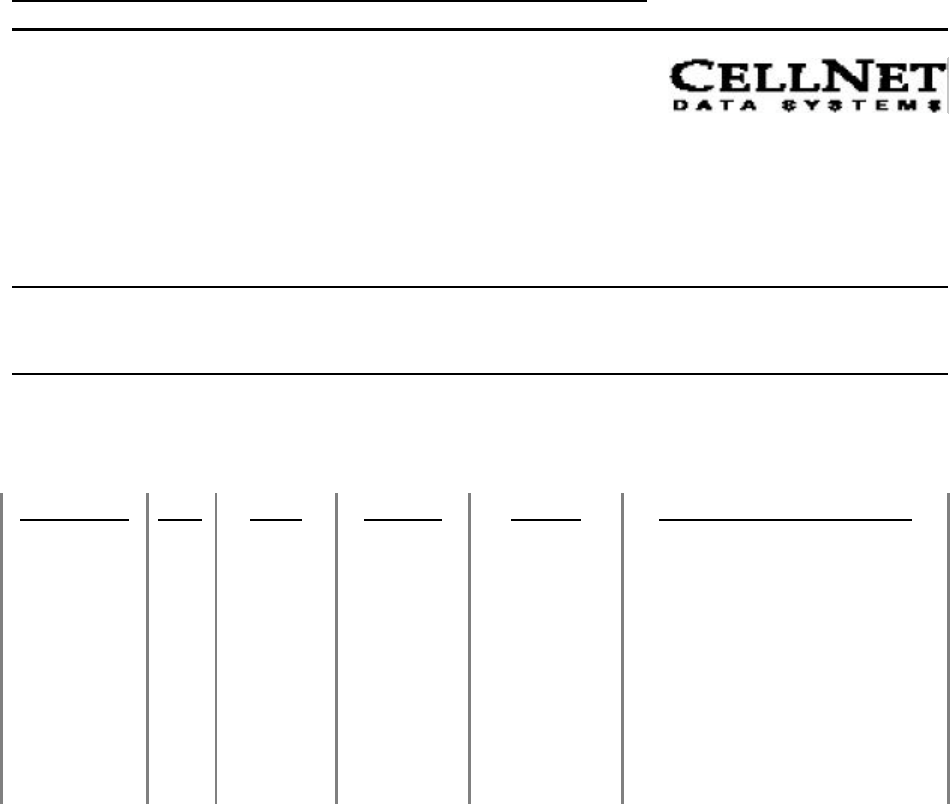
4.3 Carefully place module facedown on the ESD mat on the workbench after disassembly.
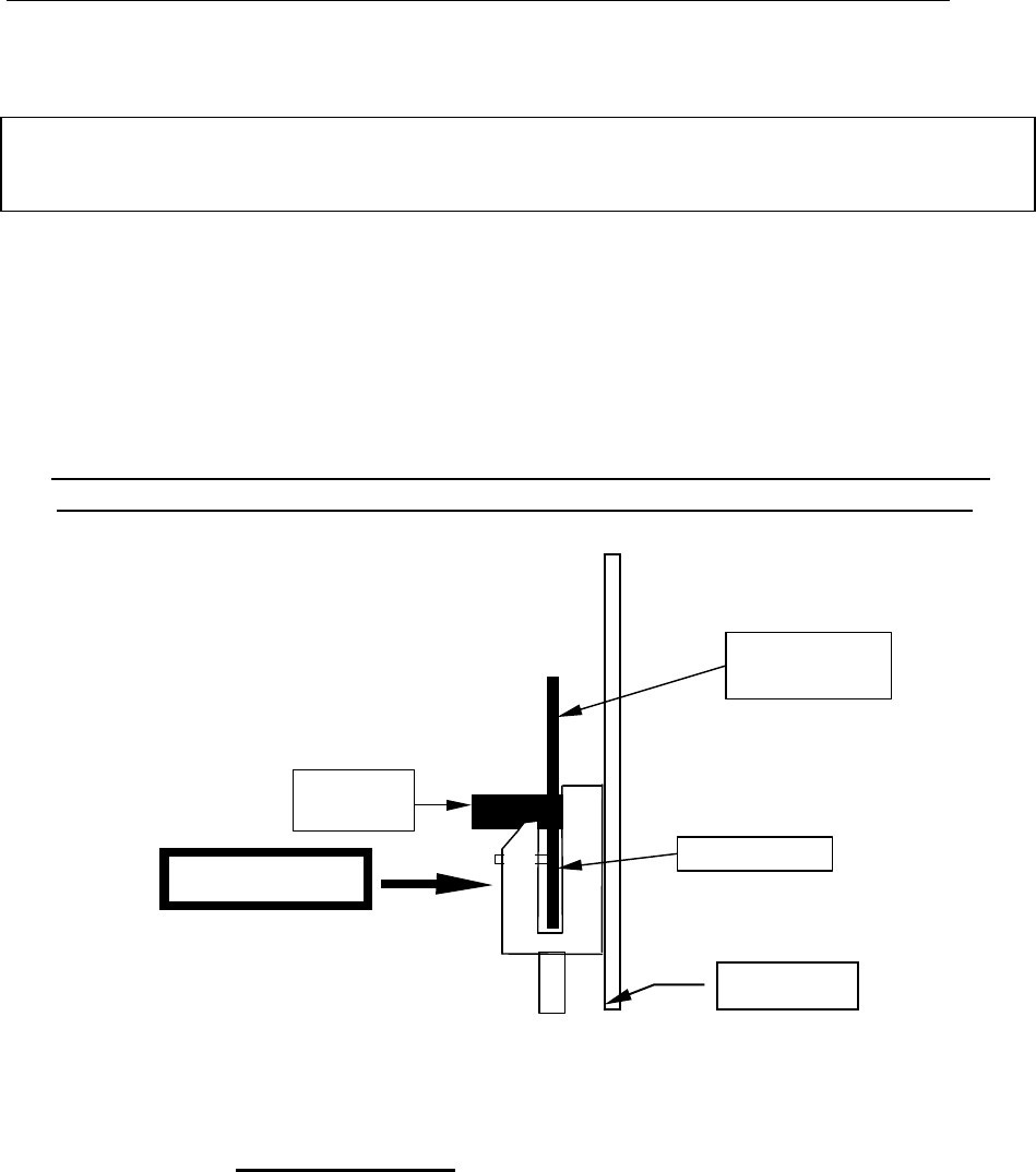
Figure 1
BAMM
Interrupter
Note: Place ESD wrist-straps on prior to module disassembly procedure.
MPI: GE, 240v, Single Phase, Remanufacturing Process
97-xxxx, Rev:A Page 5 of 13
5 AC Cable Disconnection
5.1 Disconnect AC cable from the module. Use needle nose pliers to disconnect power
leads from module. Gently grip on red AC cable tabs with needle nose pliers and
disconnect the power leads. Pay close attention not to touch PCB with pliers and not to
bend connection tabs on the board. Do not rotate tabs when disconnecting power leads.
(Refer to Figure 2)
5.2 Disconnect AC cables from Current Coil. Use needlenose pliers to disconnect power
leads from current coil. Grip on the edge of the superclip and gently remove clip from
current coils. Remove any debris resulting from disassembly of the superclip from the
copper coil.
5.3 Disregard and discard old cables.
5.4 All disassembled modules must be placed in ESD bags for storage.
Note: Old modules (RTOMM) have a different set of cables from the new generation of modules
(BAMM/BAMMCCSK). Both types of cables are NOT exchangeable. The RTOMM cables have
different inline components on each of the two cables. One of two RTOMM cables has a fuse
incorporated on the cable and the other cable has a resistor incorporated on it. The
BAMM/BAMMCCSK have 2 identical cables WITHOUT in line components.
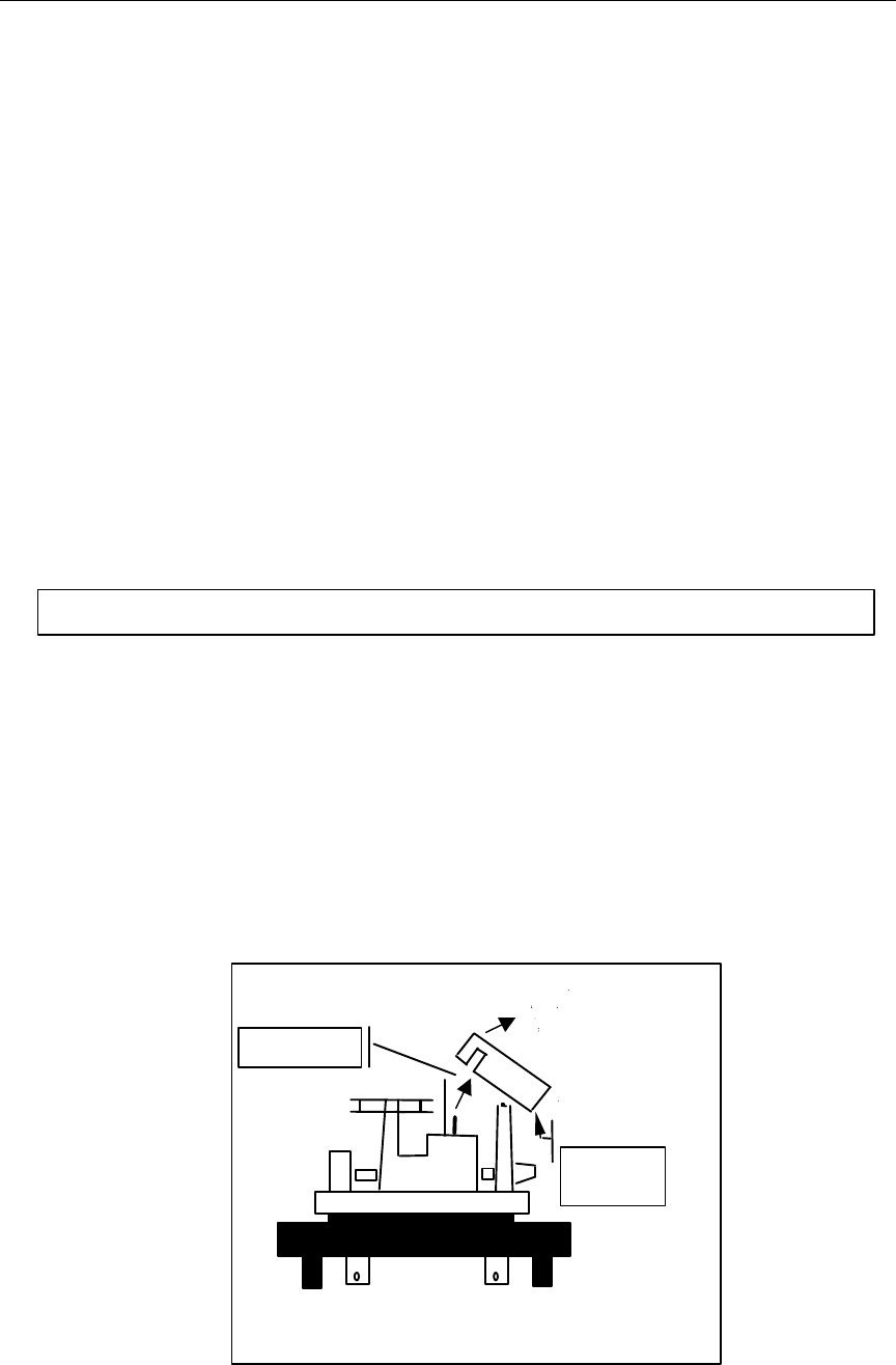
RTOMM
Component Side
Resistor cable
connector
Fuse cable
connector
Figure 2: Power Cable
Orientation

MPI: GE, 240v, Single Phase, Remanufacturing Process
97-xxxx, Rev:A Page 6 of 13
6. Interrupter Disassembly
6.1 Use needle nose pliers to remove interrupter from disk shaft. Gently pull the interrupter
from the disk shaft with the needle nose pliers. Pay close attention when removing the
interrupter and make sure that minimal force is exerted on the shaft. The shaft is
extremely sensitive to force and can easily be bent when subjected to pressure
6.2 Disregard & discard old interrupters.

MPI: GE, 240v, Single Phase, Remanufacturing Process
97-xxxx, Rev:A Page 7 of 13
ASSEMBLY INSTRUCTIONS
Important Regulatory Requirements/Statements
This device complies with part 15 of the FCC rules. Operation is subject to the following
two conditions: (1) This device may not cause harmful interference, and (2) this device
must accept any interference received, including interference that may cause undesired
operation.
This device must accept any interference received, including interference that may
cause undesired operation.
The BAMMCCSK module is factory installed and is inaccessible to the user. The
module must be sent back to the factory for any retrofit or maintenance required.
The antenna used for this transmitter must be installed to provide a separation distance
of at least 20cm from all persons and must not be co-located or operating in
conjunction with any other antenna or transmitter.
The BAMMCCSK module is designed to transmit only using one loop antenna having
omnidirectional gains of not more than 0 dBi.
7.1 Power Cable Installation
Note: Make sure to use the correct AC cables. The 240V BAMM and BAMMCCSK use the
black AC cables WITHOUT the in-line components. Refer to the addendum part of
the MPI for the soldering procedure ond 120V GE Meters.
7.1.1 Using the wire installation tool grip the superclip along its ears, open the pliers
and place the clip onto the current coil, near the end on a straight portion of the
coil. When attaching the superclips to the current coil, install the clips as shown
in the diagrams below, with the wire exiting the superclip towards you.
Notes:
1. Never place a superclip over the insulated portion of a current coil.
2. Jaw opening on the clip installation tool must be set to predetermined
dimension:
a) for GE I70 S-I, jaw opening = 0.22
b) for GE I70 S-II, Jaw opening = 0.34
3. It is preferred to have all clip prongs engaged with the current coil. On
some meters, due to size of current coil and clip, the upper prongs do not
become engaged. Acceptance criteria for clip engagement is:
Clip must not slip on current coil by pulling (slight tug) on the wire.
MPI: GE, 240v, Single Phase, Remanufacturing Process
97-xxxx, Rev:A Page 8 of 13
4. Do not attempt to re-use the wire. Reject the wire.
BAMM/BAMMCCSK AC Cable Assy.
Spring clip
Current Coil
Superclip placement on the
current coil
BAMM
BAMM CCSK/
BAMM AC
Cables (2X)
MPI: GE, 240v, Single Phase, Remanufacturing Process
97-xxxx, Rev:A Page 9 of 13
7.1.2 Use the needlenose pliers to grip the AC cable fast-on connector, then press it fully onto
the fast-on tab on the BAMM/BAMMCCSK. Repeat for the other cable.
Note: Do not attempt to straighten a BAMM/BAMMCCSK fast-on tab that is bent. If the
fast-on connector cannot be fully seated onto the tab because the tab is bent too
much, reject the BAMM/BAMMCCSK.
8. Interrupter Installation
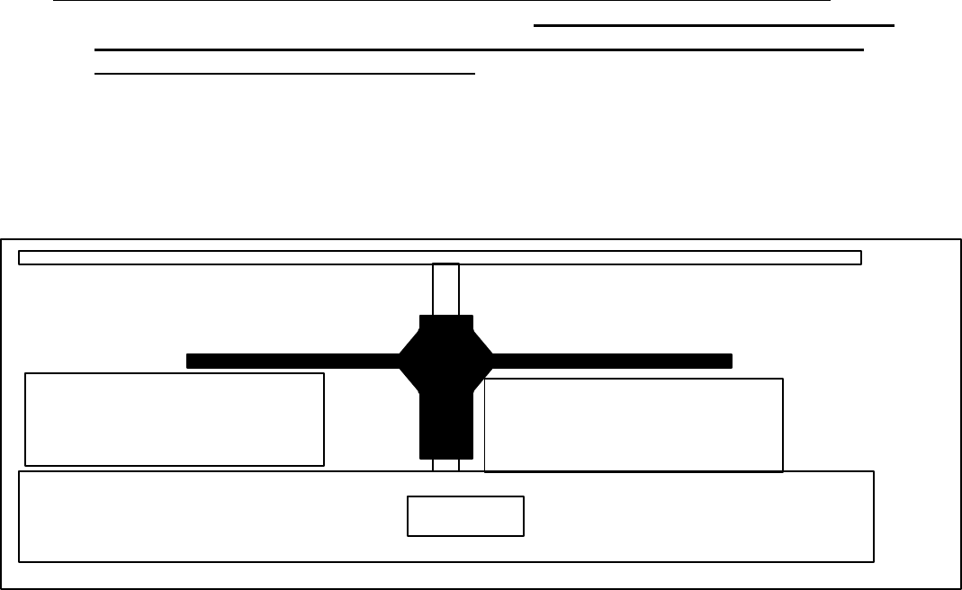
8.1 Insert the interrupter into the interrupter installation tool as shown below. It is important
that the interrupter and the interrupter tool are properly oriented.
Handle the interrupter from long side of hub not the interrupter blades. Do
not touch the interrupter blades as you insert the interrupter into the tool.
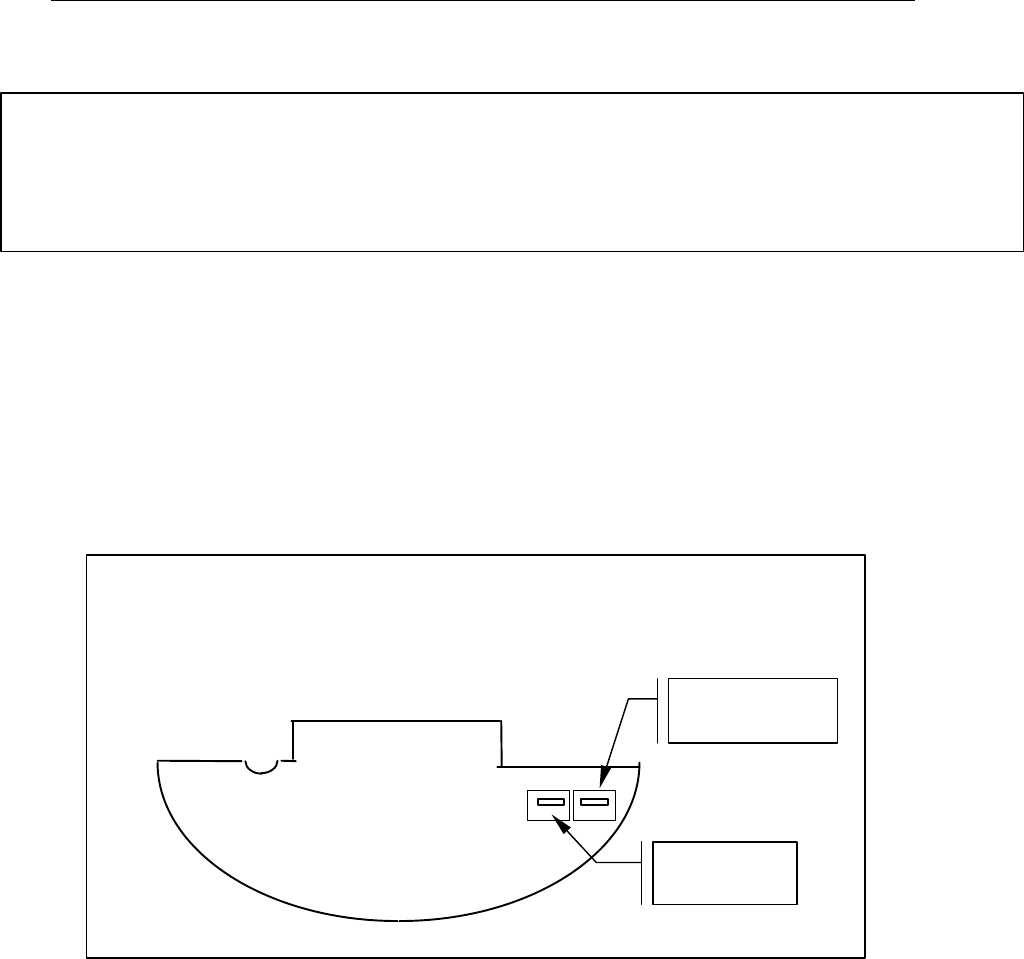
Figure 3: Interrupter Installation
8.2 Carefully position the interrupter next to and parallel to the meter shaft with the spacer
side 2of the tool resting totally flush on the bottom of the meter disk. Use your finger or
thumb to press the tool totally flush against the disk when you snap the interrupter onto
the disk.
8.3 Verify that the installation tool is held perfectly vertical, then gently squeeze the pliers until
the interrupter snaps onto the meter shaft. If you don’t feel or hear the ‘snap’, the
interrupter might be damaged or in the wrong position.
interrupter
letter ‘G’
on this side
long side
of hub
meter disk
finger pressure
MPI: GE, 240v, Single Phase, Remanufacturing Process
97-xxxx, Rev:A Page 10 of 13
8.4 Remove the interrupter tool from the meter base. Make certain that the interrupter blade
is not twisted while removing the tool. Gently release the tool from the interrupter
before removing the tool from the meter.
8.5 Using 0.025” feeler gage, check for interrupter blade- meter base clearance. The
clearance should be checked for all blades and meter base on both sides of shaft. If
clearance is less than feeler size(0.025”), the interrupter must be removed and a new
interrupter installed. Repeat interrupter placement procedure. If the clearance is still less
than 0,025place the meter aside and do not reuse meter. Acceptable versus
unacceptable contact can be evaluate by inserting the feeler gage between the interrupter
and the base without touching the disk or interrupter with anything else. If the interrupter
and disk rotate even slightly when the feeler gage is inserted, there is unacceptable
contact. Place the feeler gage closer to the end of the interrupter blades rather than
closer to the disk shaft because the webbing of the interrupter could give a
false failure reading.
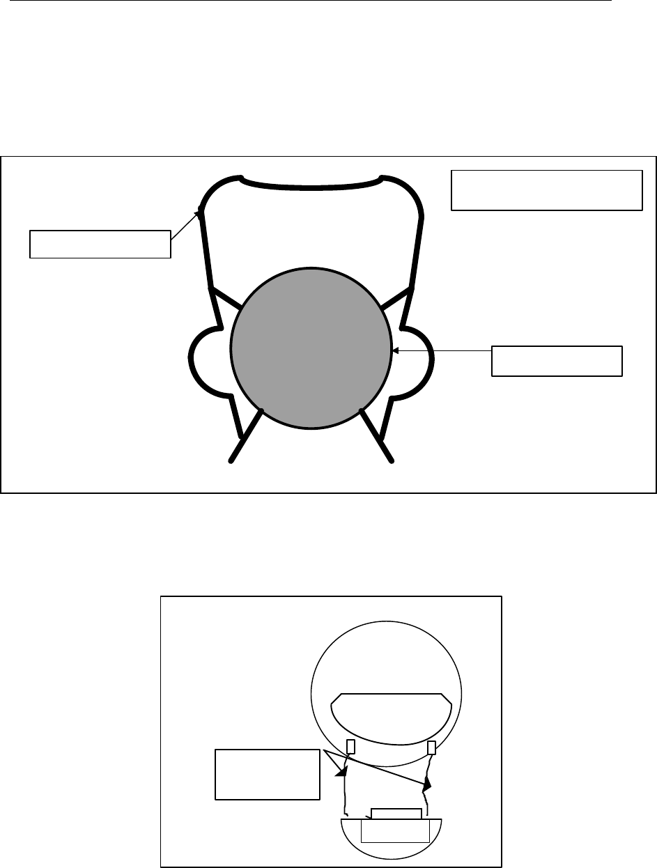
Figure 4: Checking Proper Interrupter Instalation
9.0 BAMM/BAMMCCSK Installation
9.1 Take the new barcode label and attach it to the front face of the BAMM/BAMMCCSK.
Make sure the label is square and does not interfere with any holes or writing on the
enclosure. Verify the quality of the label print and the utility meter ID on the label matches
the original label on the module. If there is a discrepancy between old and new label serial
number, investigate the problem and print and attach the correct label.
9.2 Position the BAMM/BAMMCCSK onto the meter standoffs by rotating the
BAMM/BAMMCCSK upwards and over the interrupter. Use the electric torque driver (set to
5 in-lbs) to secure the TOMM to the meter using two module mounting screws. Be very
careful not to damage the screw heads.
9.3 Again rotate the disk gently to verify that there is no interference with the interrupter
against the meter or BAMM/BAMMCCSK.
meter base
good location to place feeler gage.
meter passes
bad location to place feeler gage.
meter OK, but fails test
MPI: GE, 240v, Single Phase, Remanufacturing Process
97-xxxx, Rev:A Page 11 of 13
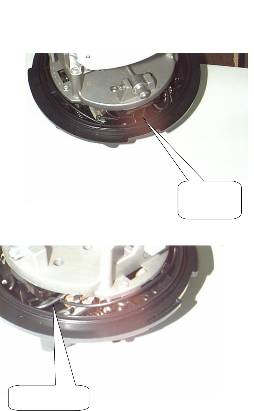
9.4 Position the AC cables low around the perimeter of the meter base, but not into the
BAMM/BAMMCCSK housing. Excess cable is folded over for both wires on the clip side.
9.5 Install the meter cover. Make sure the power cables are not pinched by the cover.
Fold excess wires
as shown.
Fold over the excess
wire as shown.

MPI: GE, 240v, Single Phase, Remanufacturing Process
97-xxxx, Rev:A Page 12 of 13
Figure 5:Proper AC cable Installation and Routing
10. Tools and Materials Required for 120V Meter Module Assembly
NOTE: A grounded wriststrap must be worn during assembly.
The following tools and materials are required for meter retrofit:
CellNet Part No. Description Used On Quantity
19-0109 120V AC BAMM cable 120V BAMM 2
n/a Hakko soldering iron #936, non-ESD, temperature 120Va/r
controlled base, adjustable wattage (or equivalent)
n/a Metcal tip #STTC-137, chisel point (or equivalent) 120V a/r
n/a 22AWG wire stripper/cutter 120V a/r
n/a Sn 63 RA solder Kester# 285 120V a/r
n/a Solder braid 120V a/r
n/a Foam tipped applicator for flux/solder joint cleaning 120V a/r
n/a Isopropal alcohol for flux/solder joint cleaning 120V a/r
MPI: GE, 240v, Single Phase, Remanufacturing Process
97-xxxx, Rev:A Page 13 of 13
11. Power Cable Installation
Note: Make sure to use the correct AC cables with the 120V BAMM. The 120V BAMM
uses the yellow AC cables without in-line components.
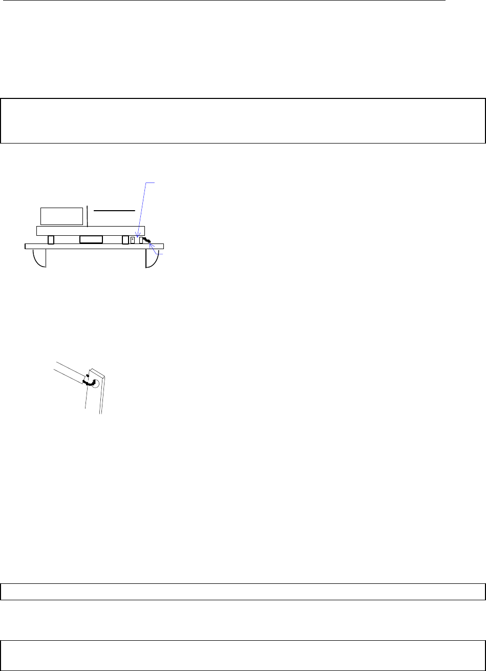
11.1 Soldering instructions for 120V meters only
Figure 7: 120v AC Cable Connection
If surface of the eyelet/tab is dirty or corroded, use foam applicator and alcohol to clean
the surface. Try not to generate any particles during this process, and be careful to
remove any particles you do generate.
Hook pre-tinned and formed wire through eyelet on meter tab and solder wire to tab.
Visually inspect meter base for excess solder. Remove any excess solder with the solder
braid and/or soldering iron.
Note: No solder splatter or solder balls are permitted inside the meter.
Clean the solder joint with alcohol to remove any residual flux. Give a slight tug on the
wire to ensure the solder is securely attached to the tab.
Note: Tab may remain hot for a few seconds. Wait 5-10 seconds before routing the cable
near the tab.
One of these two tabs will NOT have a
meter wire installed. Use this one for the
BAMM cable
Meter wire

MPI: GE, 240v, Single Phase, Remanufacturing Process
97-xxxx, Rev:A Page 14 of 13