Schlumberger Sema CMM1402 Wireless Gas Meter Reader User Manual RG3RemoteAntennaInstSOP
Schlumberger Sema Wireless Gas Meter Reader RG3RemoteAntennaInstSOP
Manual

STANDARD OPERATING PROCEDURE
COPYRIGHT © 2000
SCHLUMBERGER RESOURCE MANAGEMENT SERVICES, INC.
ALL RIGHTS RESERVED.
RG3 Remote Antenna Install SOP
Revision Comments Date Author
1.0 First Draft 06/06/01 Justin Steves
Contact
Justin Steves Phone:
Pager:
Email:
650-632-2610
1-800-351-7041
jsteves@san-carlos.rms.slb.com
Contents
Acronyms.................................................................................................................................2
Related Documents...............................................................................................................2
1.0 Introduction...................................................................................................................3
2.0 Required Tools.............................................................................................................4
3.0 Module and Part Numbers..........................................................................................5
4.0 General Guidelines......................................................................................................6
5.0 Procedure .....................................................................................................................8
SCHLUMBERGER RMS PROPRIETARY
STANDARD OPERATING PROCEDURE
2 –SOP Title
Acronyms
RG3 Residential Gas 3 Modules
RIMS Retrofit information management system - SLB
proprietary shop floor control system
HH Hand Held Computer “DAP” “SYMBOL” or “PSION”
PSR Packet Success Rate - A formula that compares the
number of times that we have received a signal from a
module with the number of times that we should have
received a signal.
Remote Antenna Refers to the omni whip antenna which will be
"remoted". It is this antenna which is ideally "line of
sight" of the MCC.
Link Assessment
Tool (LAT) This is a Schlumberger tool that provides real time
feedback to the installer as to whether a site is suitable
for module installation or whether further RF fix-up is
required.
Related Documents
Document Title Part Number Revision Date
RG3 Meter Module
Installation SOP 5.0 2/2/01
Link Assessment Tool SOP 1.3 4/13/00
Targeted Selective Repeater
RF Process SOP 1.5 4/24/01
SCHLUMBERGER RMS PROPRIETARY
STANDARD OPERATING PROCEDURE
SOP Title–3
1.0 Introduction
The Residential Gas Remote Antenna provides an RF fix-up solution for Residential Gas 3
installations which cannot be heard with adequate packet success rate due to the location
of the gas meters. There are two foreseeable methods for deploying the Remote Antenna.
The first and most cost effective method is by reviewing a deployment area and
determining the need for a remote antenna up front by using tools such as a LAT .
The second and probably most common will be a replacement of a normal ResGas module
that is stale, is installed but not discovered, or has an unacceptable PSR. This is not
preferred because it requires two site visits by an installer, it increases the number of
modules in the RMA process, and there is an increase in lost data (takes longer to
automate a route).
No modifications should be made to the module, cable, or antenna without the
appropriate approval.

SCHLUMBERGER RMS PROPRIETARY
STANDARD OPERATING PROCEDURE
4 –SOP Title
2.0 Required Tools
1. Screwdriver, Flat-tip 5/16-inch by 6-inch
2. Screwdriver, Flat-tip 1/4-inch by 5-inch
3. Screwdriver, Flat-tip 3/16-inch x 4-inch
4. Screwdriver, Phillips #1 x 4-inch
5. Screwdriver, Phillips #2 x 4-inch
6. Screwdriver, Flat-tip Z-shaped
7. Awl, Heavy duty
8. Scraper , Brass 1 1/4-inch wide
9. Diagonal cutters
10. Small lineman's pliers / vice grips
11. Wire tooth brush
12. Cordless Drill
13. Drill Bit, multi-purpose 3/8” x 10”
14. Screws, 1/4” Hexagon Head x 1” Self Tapping
15. Wrench, 5/16 open ended
16. All Purpose Silicone Sealant
17. Utility knife

SCHLUMBERGER RMS PROPRIETARY
STANDARD OPERATING PROCEDURE
SOP Title–5
3.0 Module and Part Numbers
Modules
The following modules are now available for ResGas Remote Antenna Installation
• 26-2023 American RG3 with Remote Antenna
• 56-2023 American RG3 with Remote Antenna-Utility Owned
• 26-2024 Sprague RG3 with Remote Antenna
• 56-2024 Sprague RG3 with Remote Antenna-Utility Owned
• 26-2025 Equimeter RG3 with Remote Antenna
• 56-2025 Equimeter RG3 with Remote Antenna-Utility Owned
Cables
The following is the minimum required length of cable for the remote antenna. This has
an N connector on one end to connect to the antenna and an SMA connector on the other
end to connect to the module.
• 19-1584, extension cable, 20 ft
In the case where the lengths above aren't adequate, there are extension cables, ready
made with a female "N" connector on one end and a male "N" connector on the other are
available in the following lengths:
• 19-1740, extension cable, 5 ft
• 19-1741, extension cable, 10 ft
• 19-1742, extension cable, 20 ft
Remote antennas
• Omni Whip Antenna, CellNet part number: 01-1239
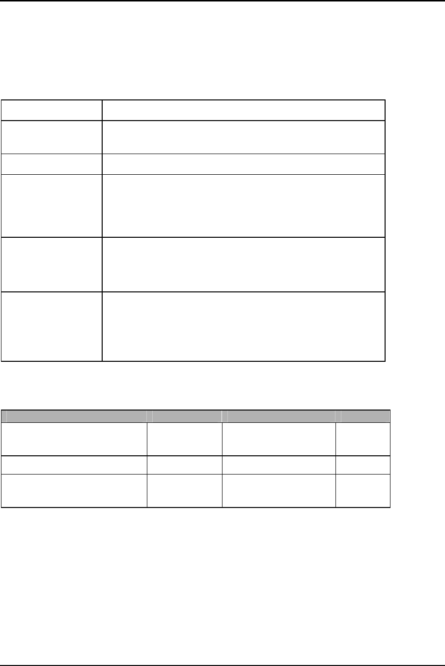
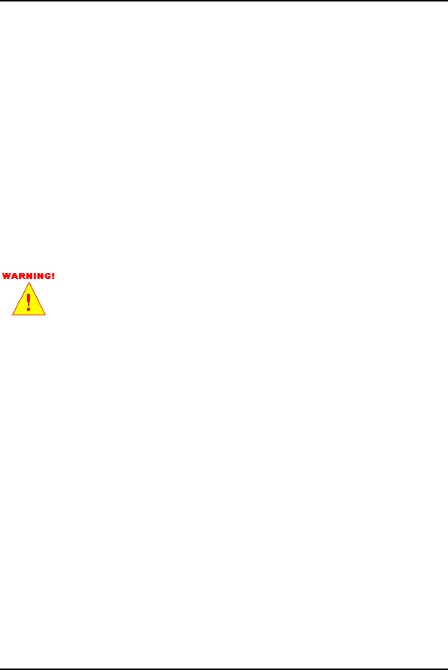
Mounting Brackets
• 28-1800, bracket, antenna, meter box, right
• 28-1801, bracket, antenna, meter box, left
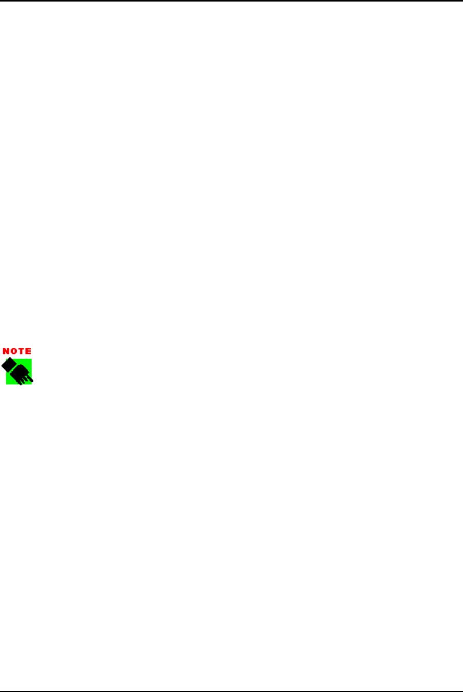
• 28-1802, bracket, antenna, ceiling mount
• 28-1804, bracket, antenna, wall, flat
SCHLUMBERGER RMS PROPRIETARY
STANDARD OPERATING PROCEDURE
6 –SOP Title
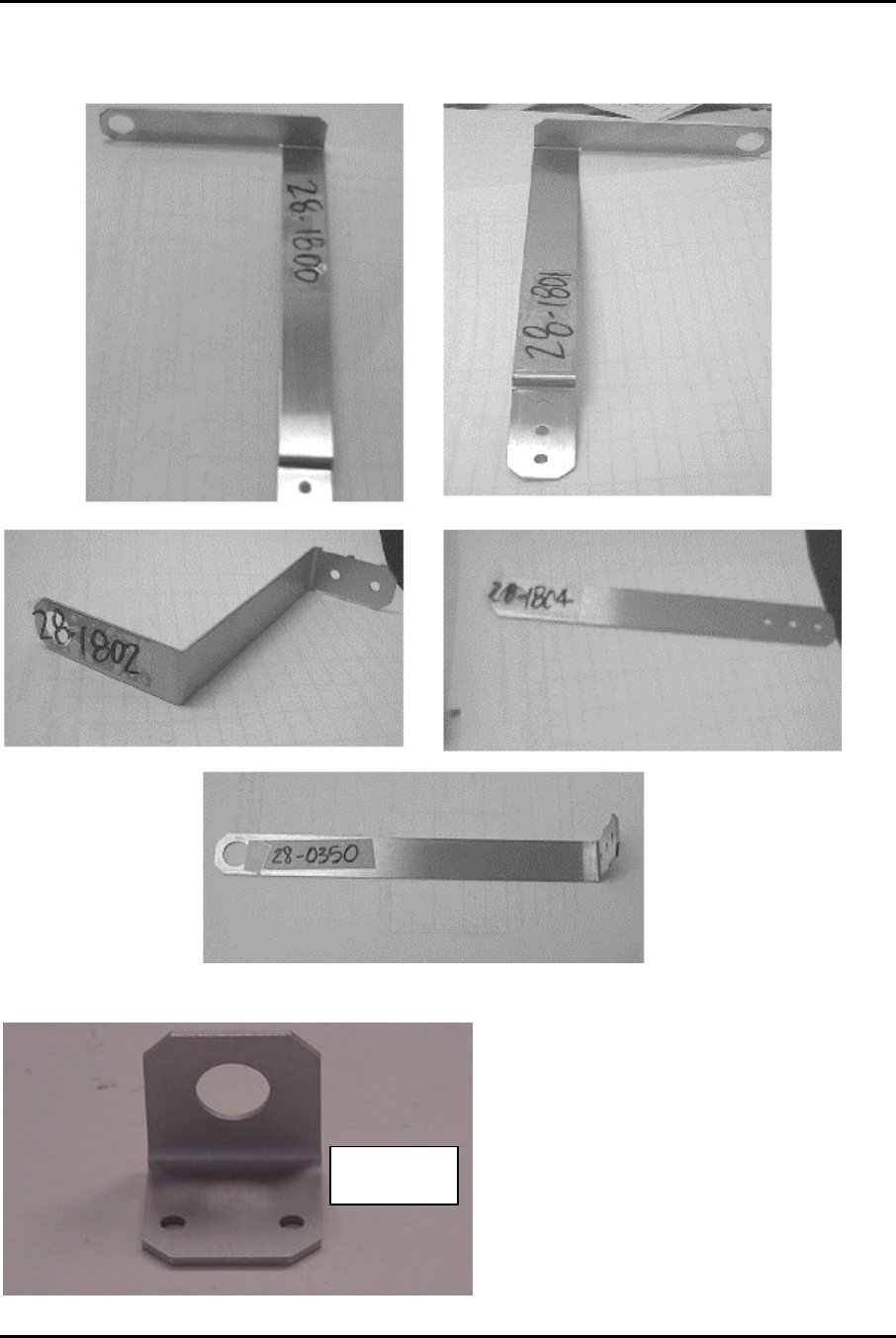
• 28-1805, bracket, antenna, small right angle
4.0 General Guidelines
Determine the optimum location for the installation of the remote antenna. This will vary
depending on the location of the meter. In general, the antenna should be:
• Installed as close to line of sight to an MCC as is possible.
• Mounted so that it is at least 4 inches from the nearest structure.
• For inside installations, remote antennas may be mounted in the proximity of an
available window, or may need to be routed to the outside if the signal strength
isn't great enough.
• Mounted so that the length of cable is minimized. The minimum cable length is 20’
due to FCC certification. While there are no specific guidelines for maximum cable
length, every 25 ft increases the RF link loss by about 2.5dB.
As a guideline for cost, when there are 5 or more modules in the same
location that are not being heard from, it is cheaper to use a selective
repeater.
SCHLUMBERGER RMS PROPRIETARY
STANDARD OPERATING PROCEDURE
SOP Title–7
Figure 1 Mounting Brackets
28-1805

SCHLUMBERGER RMS PROPRIETARY
STANDARD OPERATING PROCEDURE
8 –SOP Title
5.0 Procedure
When available use the LAT tool to determine the best location for mounting the antenna.
Ideally you will place the antenna where you hear from MCC’s the best. You may or may
not be able to hear from any MCC’s. This does not mean that the antenna will not work
since the antenna strength is greater than the antenna strength on the LAT. Ensure that
you have the correct cable length and mounting equipment for the mounting site that you
choose.
Begin by mounting the antenna in the appropriate location and runing the small end of
the cable through the wall (if mounted outside). Tie any slack in the cable neatly behind
the meter and connect the cable to the module. Follow the instructions of the RG3 Meter
Module Installation SOP. Seal any holes that you made with silicone sealant. Clean up
all debris and secure the site upon exit.