Schlumberger Sema DBDC2000 Electric, Gas, or Water Meter Reading Unit User Manual roadmaps cover
Schlumberger Sema Electric, Gas, or Water Meter Reading Unit roadmaps cover
UserManual.wiki
>
Schlumberger Sema
>
DBDC2000 User Manual
E09 User Manual
Navigation menu
Upload a User Manual
Namespaces
Wiki Guide
HTML
PDF
Info
Views
User Manual
Discussion / Help
Navigation


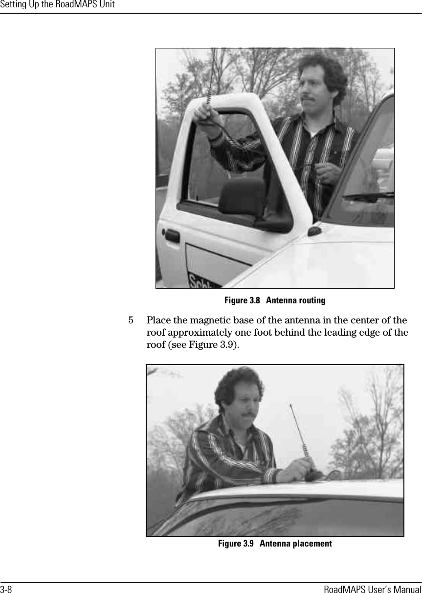
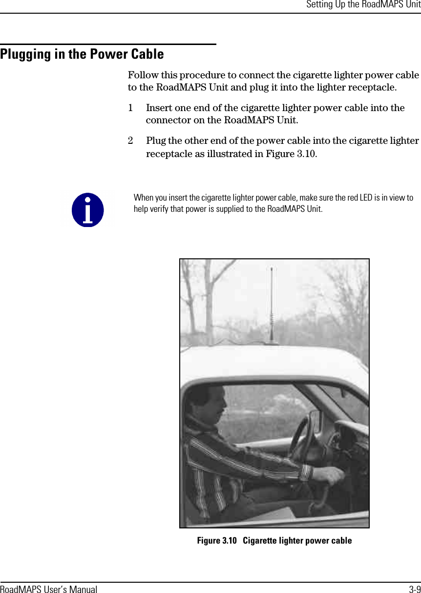
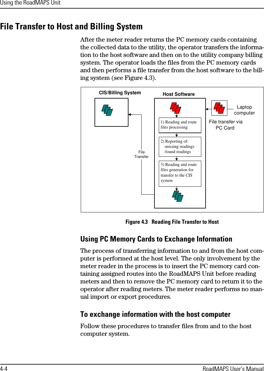
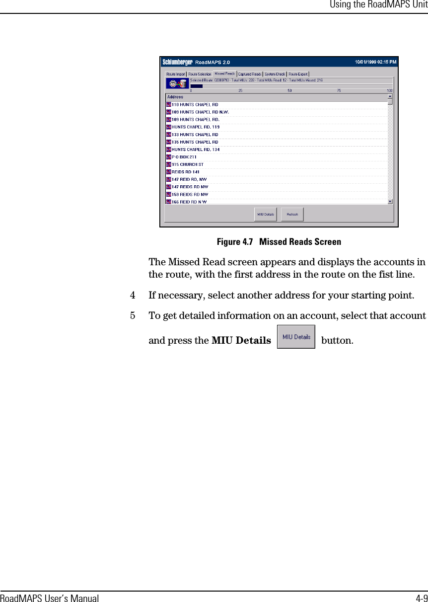
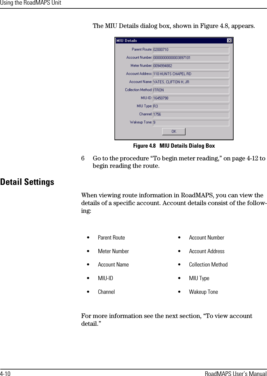
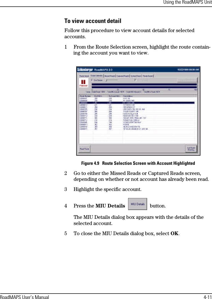
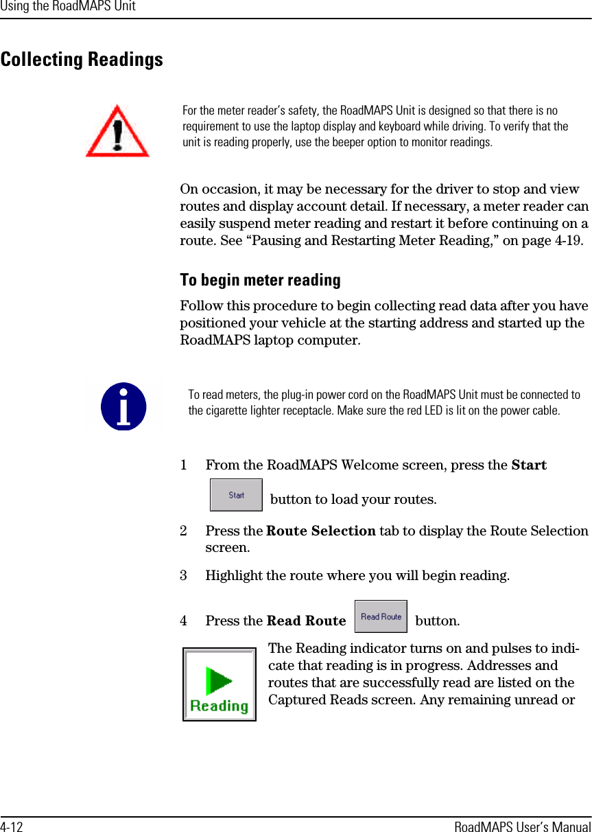
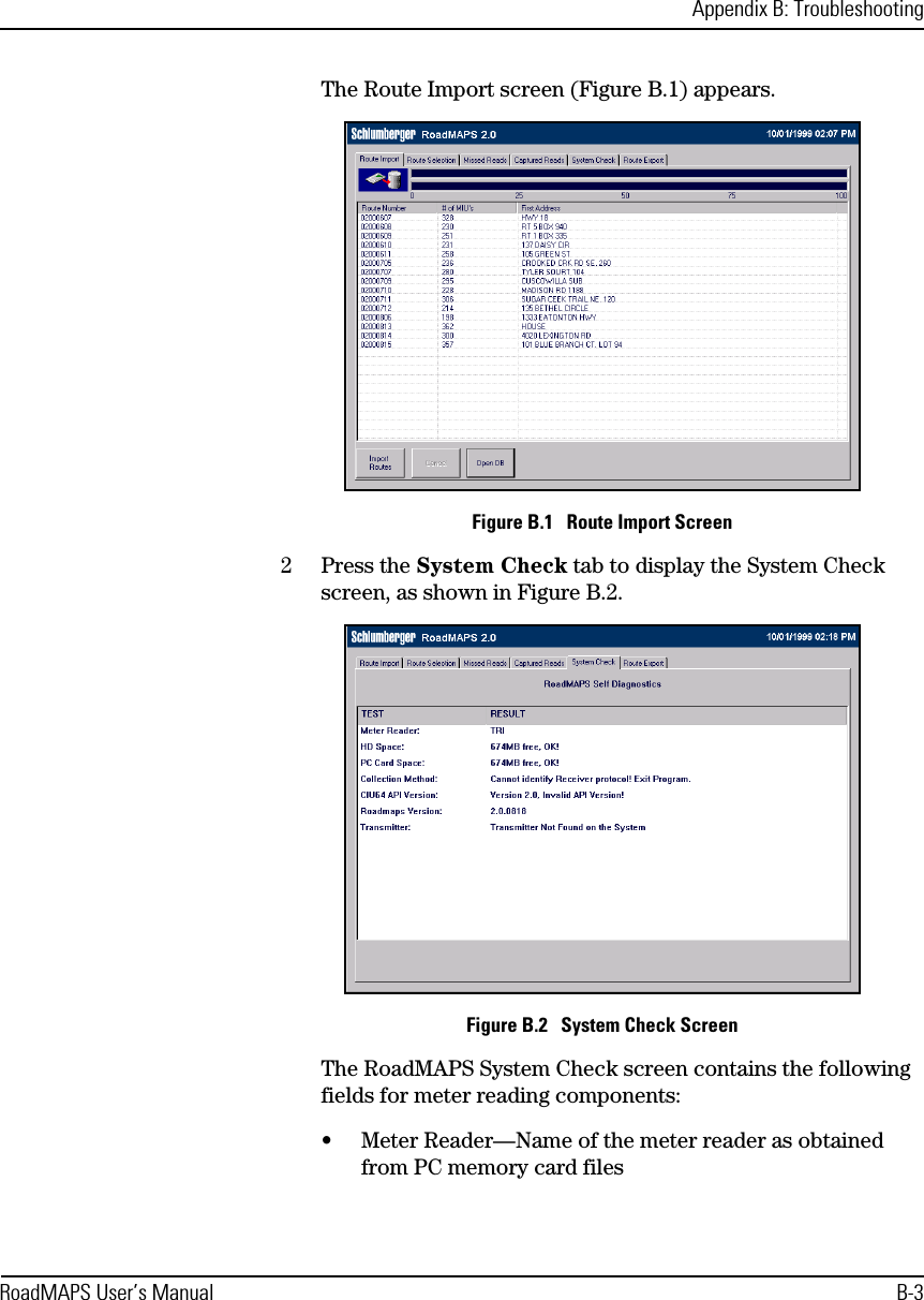
![Setting Up the RoadMAPS Unit3-10 RoadMAPS User’s ManualTurning the Unit OnWhen the laptop starts up, RoadMAPS software loads route data from the PC memory card. After the route data is loaded, RoadMAPS performs a system self test. During the self test, RoadMAPS also removes the old export file from the PC memory card after verifying that the previous data upload to the host was successful. To start RoadMAPS SoftwareFollow this procedure to turn on the RoadMAPS laptop and soft-ware and automatically load routes from the PC memory card.1With the laptop computer facing you, press the latch in to dis-engage the locking mechanism located on the front center edge of the display.2Raise the display to a comfortable viewing position with the keyboard accessible to you.3Press FN + ON and hold it for one second. The the FN key is located on the bottom row in the lower left corner of the key-board, and the ON key is located on the space bar. (See Figure 3.11). Figure 3.11 Laptop KeysEsc F1 F2 F3 F4 F5 F6 F7 F8 F9 F10 F11 F12Num LkPrt ScSysRqScr LkInsertPauseBreak Delete1!2@3#4$5%6^7&78*89(90)*Backspace-+–=TabQWERTYUIOP45 6 –0[{]}OFF¦\ASDFGHJKL1 2 3:;+"'EnterCapsLockShiftXCVBNMZ< > ?, . //ShiftPgUpPgDnEndHome~`AltAltCtrlFn ON /.Fn key ON Mouse buttons OFF](https://usermanual.wiki/Schlumberger-Sema/DBDC2000/User-Guide-69740-Page-42.png)